

Samsung RF22K9381, RF28K9070, RF28K9380 Troubleshooting Manual
Fast Track Troubleshooting
Model:
RF28K9070
RF22K9381
RF28K9380
Production; DRRF28K9070
- 060616
IMPORTANT SAFETY NOTICE – “For Technicians Only” This service data
sheet is intended for use by persons having electrical, electronic, and mechanical experience
and knowledge at a level generally considered acceptable in the appliance repair trade. Any
attempt to repair a major appliance may result in personal injury and property damage. The
manufacturer or seller cannot be responsible, nor assume any liability for injury or damage of any
kind arising from the use of this data sheet.
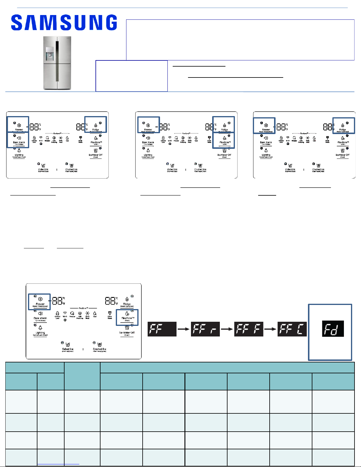
Hold Freezer and Flex zone for 6 seconds until screen
goes blank and you hear a beep . Press Flex zone again
to enter first mode 1
To exit; after mode 5 the screen will be blank, if left
alone for 1min, it will exit to normal operation
DISPLAY
Operating
Time
Operation
Freezer Fridge
F-Fan
(Freezer)
R-Fan
(Fridge)
CV-Fan
(FlexZone)
F Valve R Valve CV Valve
FF 24hr
Continuous
operation
The
temperature
is controlled
Continuous
operation
Swing Swing Swing
FF r 24hr
Continuous
operation
Continuous
operation
Continuous
operation
OFF ON OFF
FF F 24hr
Continuous
operation
Continuous
operation
Continuous
operation
ON OFF OFF
FF C 24hr
Continuous
operation
Continuous
operation
Continuous
operation
OFF OFF ON
mode 1 mode 2 mode 3 mode 4
mode 5
FD = Defrost, all
heaters will
turn on
Demo MODE / Cooling off
Mode
Hold buttons - Freezer, Fridge
and Door Alarm for 6 seconds
until 0 –FF is displayed. Repeat
to exit
Force Mode / Defrost
Load Mode
Diagnostic Mode
Hold buttons - Freezer, Fridge
and Flex Zone for 6 seconds. All
on/off LED’s will blink. Stop
pressing buttons to view load
status.
Refer to PAGE 3 for more detail
Hold buttons – Freezer and
Fridge for 6 seconds, screen will
blink, continue to hold until
blank screen or errors displayed.
After 1 min the mode will exit
Refer to PAGE 4 to 6 for Error
Code details
Support Information:
HELP: 1-888-751-4086 (Tech Sup. – ASC/SSD) - 1-866-894-0637 (Tech Sup. - FE/ME)
GSPN: http://gspn3.samsungcsportal.com/main.jsp
E-Learning: samsungasc.earlyconnect.com
MCP & E-Learning Support: 1-800-749-9421 – e-learning@sea.samsung.com
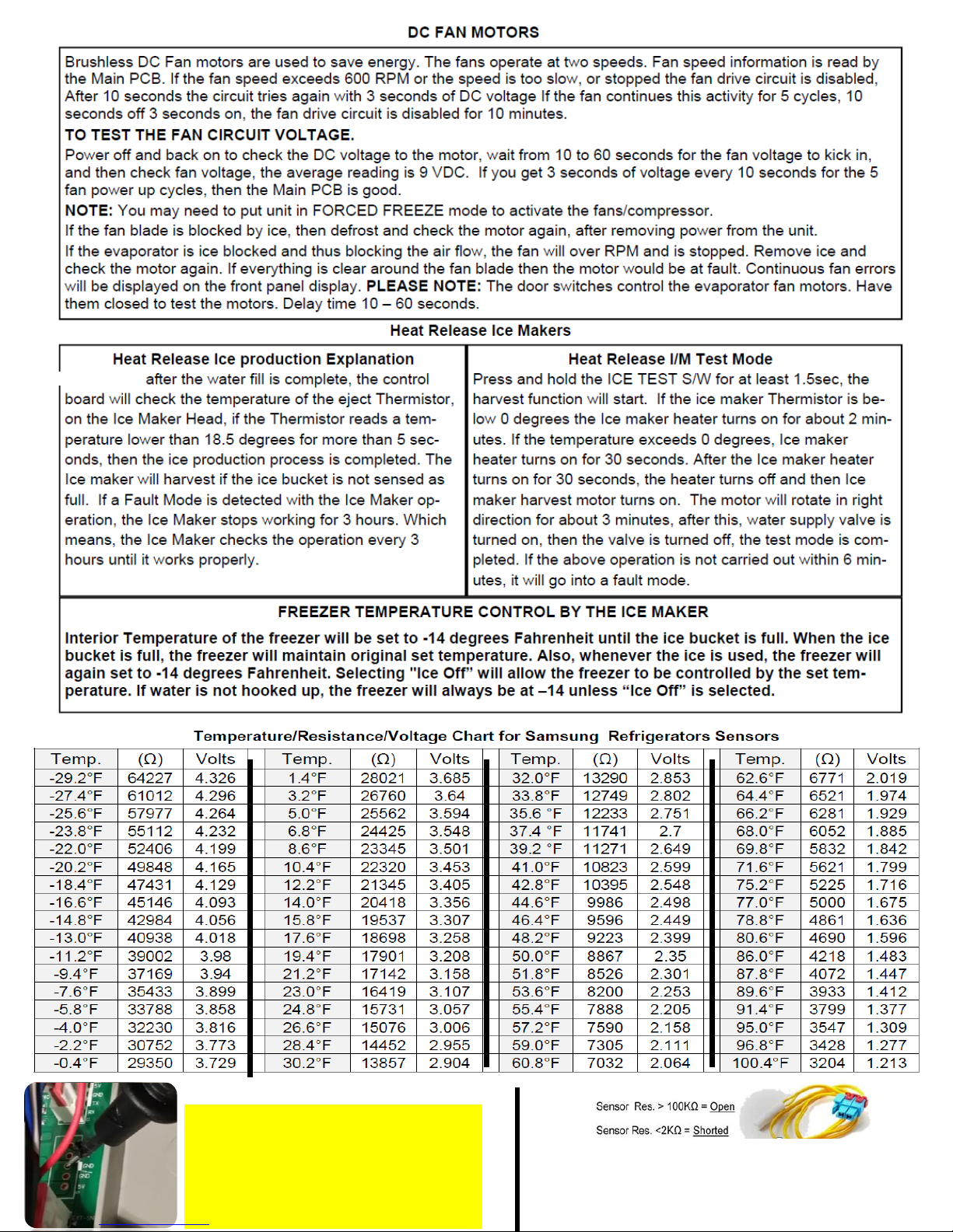
Make sure before measuring voltage of any
DC component that circuit ground is used.
Any marked GND on the main PCB will be
your circuit ground.
If Chassis ground is used, measurements
will be incorrect.
A Sensor Resistance over 100K ohm is considered OPEN
A Sensor Resistance under 2K ohm is considered Shorted
But Note that a sensor could also give wrong values if it is
out of tolerance
Some time
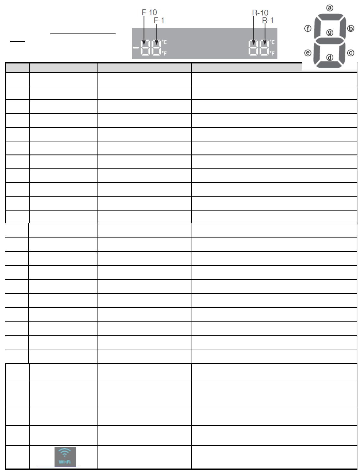
NO Part DISPLAY LED Description
1 R-FAN HIGHEST
"a" and "b" at the lowest order digit of the R
compartment
In the case of the R-FAN HIGHEST operation, the corresponding LED is turned
on.
2 R-FAN HIGH
"a" at the lowest order digit of the R
compartment
In the case of the R-FAN HIGH operation, the corresponding LED is turned on.
3 R-FAN LOW
"b" at the lowest order digit of the R
compartment
In the case of the R-FAN LOW operation, the corresponding LED is turned on.
4 Overload
"e" at the lowest order digit of the R
compartment
If the external air temperature is 34℃ or higher, the corresponding LED is turned
on.
5 Low Temperature
"f" at the lowest order digit of the R
compartment
If the external air temperature is 21℃ or less, the corresponding LED is turned
on.
6 Demo Mode
"g" at the lowest order digit of the R
compartment
The LED is turned on in Demo Mode.
7 COMP
"a" at the lowest order digit of the F
compartment
In the case of the F COMP operation, the corresponding LED is turned on.
8 F-FAN HIGHEST
"b" and "c" at the lowest order digit of the F
compartment
In the case of the F-FAN HIGHEST operation, the corresponding LED is turned
on.
9 F-FAN HIGH
"b" at the lowest order digit of the F
compartment
In the case of the F-FAN HIGH operation, the corresponding LED is turned on.
10 F-FAN LOW
"c" at the lowest order digit of the F
compartment
In the case of the F-FAN LOW operation, the corresponding LED is turned on.
11 F compartment defrost heater
"d" at the lowest order digit of the F
compartment
The LED is turned on when the freezer defrosting heater operates.
12 C-FAN HIGHEST
"e" and "f" at the lowest order digit of the F
compartment
In the case of the C-FAN HIGHEST operation, the corresponding LED is turned
on.
13 C-FAN HIGH
"e" at the lowest order digit of the F
compartment
In the case of the C-FAN HIGH operation, the corresponding LED is turned on.
14 C-FAN LOW
"f" at the lowest order digit of the F
compartment
In the case of the C-FAN LOW operation, the corresponding LED is turned on.
15 F Valve
"b" at the second lowest order digit of the F
compartment
In the case of the F valve open, the LED is turned on.
16 CV Valve
"c" at the second lowest order digit of the F
compartment
If the CV valve opens, the LED is turned on.
17 R Valve
"f" at the second lowest order digit of the F
compartment
If the R valve opens, the LED is turned on.
18 French Heater
"g" at the second lowest order digit of the F
compartment
In the case of the French Heater operation, the corresponding LED is turned on.
19 CV-FAN HIGHEST
“Freezer” or “Thin Ice” for the CV
compartment
In the case of the CV-FAN HIGHEST operation, the corresponding LED is turned
on.
20 CV-FAN HIGH “Freezer” for the CV compartment In the case of the CV-FAN HIGH operation, the corresponding LED is turned on.
21 CV-FAN LOW “Thin Ice” for the CV compartment In the case of the CV-FAN LOW operation, the corresponding LED is turned on.
Hold buttons - Freezer, Fridge and Flex
Zone for 6 seconds. All on/off LED’s will
blink, Stop pressing to view load status.
Refer to next
Load Mode
22
CV compartment defrosting
heater
“Fridge” for the CV compartment
When the CV compartment defrosting heater operates,
the LED is turned on.
23 Normal
"e" and "f" in the lowest order digits of the R
compartment, and the LEDs are all turned off.
When the external temperature is within the range of
22℃~ 33℃.
24 Ice Room-FAN
"d" at the second lowest order digit of the F
compartment
When Ice Room-FAN operates, applicable LED ON.
25 Ice maker full
“e" at the second lowest order digit of the R
compartment
When the Ice Maker's Bucket is full, applicable LED ON
26 WiFi Status
Not connected to the IP sharer (AP) or the Internet: Off
Router(AP) connected: Blink
Internet connected: On
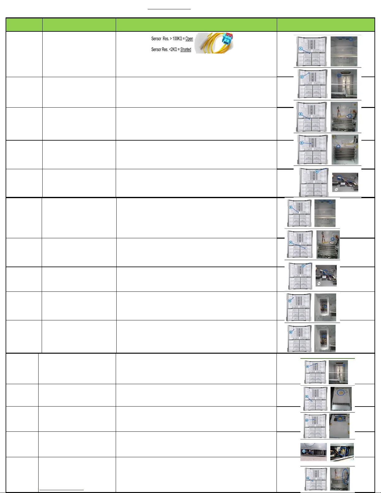
ERROR
NUMBER
Item Diagnostic method Location Image
1
Freezer sensor
error
Check if the Sensor is Open or Shorted
The voltage between the Main PCB CN30 pins 1
and 3 should be within the 4.5V~1.0V range.
2
Fridge sensor
error
Check if the sensor is open or shorted
The voltage between the Main PCB CN30 pins 1
and 5 should be within the 4.5V~1.0V range.
4
Freezer defrost
sensor error
Check if the sensor is open or shorted
The voltage between the Main PCB CN30 pins 1
and 4 should be within the 4.5V~1.0V range.
5
Fridge defrost
sensor error
Check if the sensor is open or shorted
The voltage between the Main PCB CN30 pins 1
and 6 should be within the 4.5V~1.0V range.
6
Ambient sensor
error
Check if the sensor is open or shorted
The voltage between the Main PCB CN30 pins 1
and 2 should be within the 4.5V~1.0V range.
9
Convertible zone
sensor error
Check if the sensor is open or shorted
The voltage between the Main PCB CN30 pins 11
and 12 should be within the 4.1V~0.8V range.
11
Convertible zone
defrost sensor error
Check if the sensor is open or shorted
The voltage between the Main PCB CN30 pins 11 and 13
should be within the 4.1V~0.8V range.
13
Humidity sensor
error
The voltage between the Main PCB CN30 pins 7
and 9 should be within the 4.1V~0.8V range.
14
Fridge Ice maker
sensor error
Check if the sensor is open or shorted
The voltage between MAIN PCB CN90 3↔
8 should be within 4.5V~1.0V.
15
Ice room sensor
error
Check if the sensor is open or shorted
The voltage between MAIN PCB CN30 10↔
11should be within 4.5V~1.0V.
16
Fridge humidity
sensor error
Check if the sensor is open or shorted
The voltage between the Main PCB CN30 pins 7
and 8 should be within the 4.1V~0.8V range.
21 Freezer fan error
The voltage of the MAIN PCB CN74 1↔4: should
be between 7V~12V.
22 Fridge fan error
The voltage of the MAIN PCB CN74 1↔3: should
be between 7V~12V.
23
Comp room fan
error
The voltage of the MAIN PCB CN74 1↔6: should
be between 7V~12V.
24
Freezer defrost
error
After separating MAIN PCB CN70_1 wire from PCB,
resistance value between CN70_1-7 ↔ 3 shall be 63(230)
ohm ± 7%. (Resistance value is varied by
input power) 0 ohm : heater short, ∞ ohm : wire/
bimetal open (Must power off)
Hold buttons – Freezer and Fridge for 6 seconds, screen will blink, continue to hold until blank screen or errors
displayed. After 1 min the mode will exit
Diagnostic mode
 Loading...