


PROJECTION TV RECEIVER
Chassis : P51A (REV. 1)
Model : PT54925S/SMS
PROJECTION TV RECEIVER CONTENTS
Precautions
Reference Information
Specifications
Alignment and Adjustments
Troubleshooting
Exploded View and Parts List
Electrical Parts List
Block Diagrams
Wiring Diagram
Schematic Diagrams
1.
2.
3.
4.
5.
6.
7.
8.
9.
10.

ELECTRONICS
© Samsung Electronics Co., Ltd. AUG. 2001
Printed in Korea
AA68-02048A

Reference Information
Samsung Electronics 2-1
2. Reference Information
2-1 Tables of Abbreviations and Acronyms
A
Ah
Å
dB
dBm
°C
°F
°K
F
G
GHz
g
H
Hz
h
ips
kWh
kg
kHz
kΩ
km
km/h
kV
kVA
kW
I
MHz
Ampere
Ampere-hour
Angstrom
Decibel
Decibel Referenced to One
Milliwatt
Degree Celsius
Degree Fahrenheit
degree Kelvin
Farad
Gauss
Gigahertz
Gram
Henry
Hertz
Hour
Inches Per Second
Kilowatt-hour
Kilogram
Kilohertz
Kilohm
Kilometer
Kilometer Per Hour
Kilovolt
Kilovolt-ampere
Kilowatt
Liter
Megahertz
MV
MW
MΩ
m
µA
µF
µH
µm
µs
µW
mA
mg
mH
mI
mm
ms
mV
nF
Ω
pF
Ib
rpm
rps
s
V
VA
W
Wh
Megavolt
Megawatt
Megohm
Meter
Microampere
Microfarad
Microhenry
Micrometer
Microsecond
Microwatt
Milliampere
Milligram
Millihenry
Milliliter
Millimeter
Millisecond
Millivolt
Nanofarad
Ohm
Picofarad
Pound
Revolutions Per Minute
Revolutions Per Second
Second (Time)
Volt
Volt-ampere
Watt
Watt-hour
Table 2-1 Abbreviations

Reference Information
2-2 Samsung Electronics
Table 2-2 Table of Acronyms
ABL
AC
ACC
AF
AFC
AFT
AGC
AM
ANSI
APC
APC
A/V
AVC
BAL
BPF
B-Y
CATV
CB
CCD
CCTV
Ch
CRT
CW
DC
DVM
EIA
ESD
ESD
FBP
FBT
FF
FM
FS
GND
G-Y
H
HF
HI-FI
IC
IC
IF
Automatic Brightness Limiter
Alternating Current
Automatic Chroma Control
Audio Frequency
Automatic Frequency Control
Automatic Fine Tuning
Automatic Gain Control
Amplitude Modulation
American National Standards Institute
Automatic Phase Control
Automatic Picture Control
Audio-Video
Automatic Volume Control
Balance
Bandpass Filter
Blue-Y
Community Antenna Television (Cable TV)
Citizens Band
Charge Coupled Device
Closed Circuit Television
Channel
Cathode Ray Tube
Continuous Wave
Direct Current
Digital Volt Meter
Electronics Industries Association
Electrostatic Discharge
Electrostatically Sensitive Device
Feedback Pulse
Flyback Transformer
Flip-Flop
Frequency Modulation
Fail Safe
Ground
Green-Y
High
High-Frequency
High Fidelity
Inductance-Capacitance
Integrated Circuit
Intermediate Frequency
I/O
L
L
LED
LF
MOSFET
MTS
NAB
NEC
NTSC
OSD
PCB
PLL
PWM
QIF
R
RC
RF
R-Y
SAP
SAW
SIF
SMPS
S/N
SW
TP
TTL
TV
UHF
UL
UV
VCD
VCO
VCXO
VHF
VIF
VR
VTR
VTVM
TR
Input/output
Left
Low
Light Emitting Diode
Low Frequency
Metal-Oxide-Semiconductor-Field-Effect-Tr
Multi-channel Television Sound
National Association of Broadcasters
National Electric Code
National Television Systems Committee
On Screen Display
Printed Circuit Board
Phase-Locked Loop
Pulse Width Modulation
Quadrature Intermediate Frequency
Right
Resistor & Capacitor
Radio Frequency
Red-Y
Second Audio Program
Surface Acoustic Wave(Filter)
Sound Intermediate Frequency
Switching Mode Power Supply
Signal/Noise
Switch
Test Point
Transistor Transistor Logic
Television
Ultra High Frequency
Underwriters Laboratories
Ultraviolet
Variable-Capacitance Diode
Voltage Controlled Oscillator
Voltage Controlled Crystal Oscillator
Very High Frequency
Video Intermediate Frequency
Variable Resistor
Video Tape Recorder
Vacuum Tube Voltmeter
Transistor
IC507 EL4583CN (OPTION)
IC665 TDA7265
IC904 KS24C04
ICP02 MC14528BCP (OPTION)
ICS801 TNY253P
ICS802 PC123
IC601 TDA7429S
IC602 KA4558
IC905 PCF8574P
ICV01 TA8851BN
ICV02,ICV03 HCF4053BE
ICP01 SDA 9488X
ICP02 4931
IC101 TDA9850
IC101 LA7565B
IC471 TL494CN
IC491 74HC123P
ICZ104,ICZ103 STK392-040
IC301 LA7845
IC801 STR-F6656
IC802 SVD001
IC804 SE110N
IC806 PS2561
IC501,IC531,IC561 TDA6111Q
IC01 UPD 64082GF
IC02 UPC1862GS
IC03 5412222
1
2
3
4
5
6
7
8
9
10
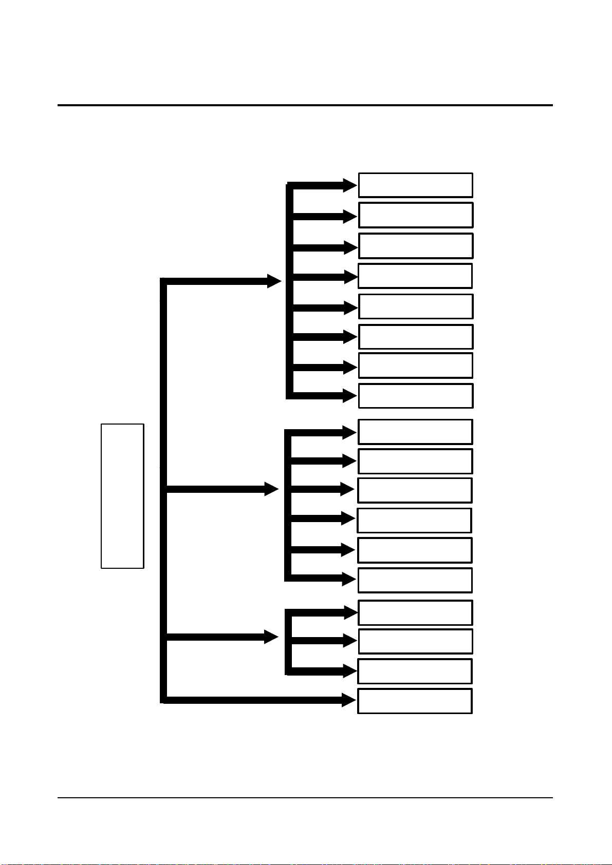
Block NameNo. IC Location IC Name
Table 2 - 3 IC Line - Up
Reference Information
Samsung Electronics 2-3
2-2 IC Line Up
2-2-1 Progressive
MAIN
TERMINAL BOARD
PIP
MTS MODULE
IF MODULE
HV MODULE
CONVERGENCE
SUB
CRT
3D-COMB
Reference Information
2-4 Samsung Electronics
11
12
13
Block NameNo. IC Location IC Name
Table 2 - 3 IC Line - Up (Continued)
FORMAT-CONVERTER
PROSCAN
3D-PHONIC
IC01 FS310KBC
IC02 72V161621
IC03 Z9021106PSC
IC04 24C02
IC201 CIP3250A
IC202 VPC3215C
IC203 7705
IC204 SDS9280
ICP301 SDA9400
IC209 SDA9361
IC212 74F125
ICV02 CXA2011Q
ICY03 CXA1839Q
ICY17 74HCT221
ICD101 TL062CDT
ICD102 SAA7367
ICD103 TMS57052
ICD104 LC32464M
ICD105 Z9021106PSC
ICD106, ICD107 PCM1717E
ICD108,ICD109,ICD110,ICD111 TL062CDT
Reference Information
Samsung Electronics 2-5
1
2
3
4
5
6
7
8
9
10
IC665 TDA7265
IC904 KS24C04
ICS801 TNY253P
ICS802 PC123
IC601 TDA7429S
IC602 KA4558
IC905 PCF8574P
ICV01 TA8851BN
ICV02,ICV03 HCF4053BE
ICP01 SDA9488X
ICP02 4931
IC101 TDA9850
IC101 LA7565B
IC471 TL494CN
IC491 74HC123P
ICZ104,ICZ103 STK392-010
IC301 LA7845
IC801 STR-F6656
IC802 SVD001
IC804 SE110N
IC806 PS2561
IC501,IC531,IC561 TDA6111Q
IC01 UPD64082 GF
ICI02 CXA1686M
ICC03 CXD2043Q
Block NameNo. IC Location IC Name
Table 2 - 3 IC Line - Up
2-2-2 Interlace
MAIN
TERMINAL BOARD
PIP
MTS MODULE
IF MODULE
HV MODULE
CONVERGENCE
SUB
CRT
2D-COMB

Reference Information
2-6 Samsung Electronics
11
Block NameNo. IC Location IC Name
Table 2 - 3 IC Line - Up (Continued)
CHROMA
IC201 CXA2095S
IC203 2210
IC204, IC206 BCF4053B
IC205 CXA1839Q
Reference Information
Samsung Electronics 2-7
2-3 MICOM IIC BUS LINE -UP
2-3-1 Progressive
XLS24C02
SLAVE ADDR.: A0h
UPD6488
SLAVE ADDR.: B8h
TDA9850
SLAVE ADDR.: B4h
Z
9
0
3
7
X
(
M
I
C
O
M
IIC 1 BUS
#30 : SDA 1
#31 : SCL 1
SDA9488
PCF8574P
SLAVE ADDR.: 40h
PCF8574P
SLAVE ADDR.: 42h
TECC1070PG30A
SLAVE ADDR.: C0h
TCPN9082PC27A
SLAVE ADDR.: C6h
SDA9400
CXA2011Q
SLAVE ADDR.: 84h
IIC 2 BUS
CIP3250A
#12 : SDA 2
#11 : SCL 2
(
SLAVE ADDR.: Dch
SDA9361
SLAVE ADDR.: 8ch
CXA1839Q
SLAVE ADDR.: 8Ah
SDA9280
SLAVE ADDR.: 2ch
TA8851AN
IIC 3 BUS
# 47 : SDA 3
# 48 : SCL 3
SLAVE ADDR.: 90h
TDA7429S
SLAVE ADDR.: 80h
PCF8574P
SLAVE ADDR.: 40h
SERIAL BUS
3D-PHONIC
MODULE

Reference Information
2-8 Samsung Electronics
2-3-2 Interlace
XLS24C02
SLAVE ADDR.: A0h
UPD6488
SLAVE ADDR.: B8h
TDA9850
SLAVE ADDR.: B4h
Z
9
0
3
5
X
(
M
I
C
O
M
IIC 1 BUS
SDA9488
#30 : SDA 1
#31 : SCL 1
IIC 2 BUS
#12 : SDA 2
#11 : SCL 2
PCF8574P
SLAVE ADDR.: 40h
PCF8574P
SLAVE ADDR.: 42h
TECC1070PG30A
SLAVE ADDR.: C0h
TCPN9082PC27A
SLAVE ADDR.: C6h
CXA2095
CXA1839Q
(
TA8851AN
IIC 3 BUS
# 47 : SDA 3
# 48 : SCL 3
SLAVE ADDR.: 90h
TDA7429S
SLAVE ADDR.: 80h
PCF8574P
SLAVE ADDR.: 40h
SERIAL BUS
3D-PHONIC
MODULE

Specifications
Samsung Electronics 3-1
3. Specifications
Broadcasting System
Scanning System
Tuning Range
Antenna Impedance
Intermediate Frequency
Sound Output
Rated Voltage
W/B Coordinates
High Voltage
FUSE
Power Consumption
NTSC
Progressive Scanning
VHF : CH2 ~ CH13
UHF : CH14 ~ CH69
Cable : CH1, CH14 ~ 125
75 ohm Unbalanced
Video : 45.75 MHz
Sound : 42.25 MHz
Chrominance Subcarrier : 42.17 MHz
STD : 15W
FULL MAX : 20W
120V / 60 Hz
Hx : 292 Hy : 260 Y : 14.5
Lx : 293 Ly : 263 Y : 0.23
31KV
250V/6.3A
CODE NO : 3601-000300
285W

Alignment and Adjustments
Samsung Electronics 4-1
4. Alignment and Adjustments
4-1 When entering the service mode:
1. Turn on the TV, and then select “STANDARD”on the picture adjustment mode.
2. Turn off the TV (STAND-BY).
3. Enter the service mode by pressing the remote control keys in the following sequence :
MUTE 1→8→2→Power On
Note : If necessary, re-do steps 1~3.
Initial display when the service mode is switched.
SERVICE NORMAL 480P
GEOMETRICS
PICTURE
PICTURE2
SOUND
PIP
OPTION
READ
RESET
1. When a RF signal is received
SERVICE NORMAL 1080i
GEOMETRICS
PICTURE
PICTURE2
SOUND
PIP
OPTION
READ
RESET
2. When a DTV signal is received

Alignment and Adjustments
4-2 Samsung Electronics
MAIN MENU
ZOOM
COMPRESS
FREEZE
SET UP
RESET
EXIT
3. When the PC mode is switched
MAIN MENU MENU DISPLAY
CH UP/DOWN Select item by moving cursor
VOL UP/DOWN Decrease or increase the adjustment values
4. Service Mode Control Keys
Note : The PC mode can be switched to the service mode by pressing the
F.Mode Key (only on the factory remote control).

Alignment and Adjustments
Samsung Electronics 4-3
Item
TV/480P
Item
1080i
43”
53” 61”
VS
VA
VL
VSC
VE
HA
PPH
PA
UPC
LOC
132
122
114
104
0
80
100
96
128
128
132
122
114
104
0
80
100
96
128
128
114
88
114
104
0
80
100
96
128
128
HEH
HS
VAN
VBO
HSP
VS4
VA4
HS4
HA4
HP4
0
63
131
128
141
150
96
56
106
131
0
63
131
128
141
150
96
56
106
131
0
60
131
128
141
125
53
45
54
VS
VA
VL
VSC
VE
HA
PPH
PA
UPC
LOC
HEH
HS
VAN
VBO
HSP
VS4
VA4
HS4
HA4
HP4
53”
61”
Remark
128
75
114
104
0
114
100
96
128
128
0
65
131
128
139
150
96
56
106
131
91
96
62
125
53
45
54
GEOMETRIC
4-2 Facotry Data
4-2-1 Progressive

Alignment and Adjustments
4-4 Samsung Electronics
Model
Remark
OPTION
PCJ533RF
PCJ533R
PCJ534RF
PCK520R
PCJ614RF
PCK5315R
PCK6115R
Byte
Model
Byte
PCJ534R
HCJ552W
HCJ652W
BYTE 0 : 71
BYTE 1 : 54
BYTE 0 : 71
BYTE 1 : 50
BYTE 0 : 71
BYTE 1 : 44
BYTE 0 : 71
BYTE 1 : 40
BYTE 0 : 79
BYTE 1 : 41
BYTE 0 : 39
BYTE 1 : 41
Item
Remark
PICTURE
RDR
GDR
BDR
RCT
GCT
BCT
ABM
ATH
Picture
Item
Picture
20
20
20
31
31
31
1
1
RYR
RYB
GYR
GYB
GAM
HWD
HTM
HSE
2
13
12
9
12
2
1
0
Item
Remark
PICTURE 2
SBR
SCT
SCL
SHU
CTI
SSP
SFO
Picture
Item
Picture
31
7
12
8
1
2
2
POV
LTI
VML
VMD
DCT
DPC
3
2
2
3
3
1
Alignment and Adjustments
Samsung Electronics 4-5
Item
Initial Value
Item
Initial Value
43”
VS
VA
VCP
VLN
VSC
HS
HPC
HA
HPP
HAA
HAB
HUC
32
32
0
5
3
0
17
20
8
11
0
8
HLC
VAS
VSR
VUV
VLV
VJS
VZS
VRP
VBS
HBS
HLB
HRB
43”
Remark
8
40
25
0
0
0
0
3
3
0
15
15
GEOMETRIC
4-2-2 Interlace
Remark
Variable
Variable
Variable
Variable
Item
Initial Value
Item
Initial Value
43”
DCT
DPI
AS
DCL
ABL
POV
SFO
TA
SCT
SBT
SCR
STT
GA
1
1
1
1
1
2
1
1
5
8
7
9
32
BA
GC
BC
GAM
AFC
TO
SSP
AMS
FHS
CFS
SC
LWC
COR
PICTURE
Remark
Variable
52”
43”
32
8
8
2
2
1
5
1
0
0
30
32
50
Remark
Variable
Variable
Variable
Variable
52”
32
8
8
2
2
1
5
1
0
0
30
32
50
Alignment and Adjustments
4-6 Samsung Electronics
Item
Initial Value
Item
Initial Value
43”
PIC
HUE
BRT
55
7
8
RYR
RYB
SHP
PICTURE 2
REMARK
52”
55
7
8
43”
15
15
0
REMARK
52”
15
15
0
Item
Initial Value
43”
SEPERATE
15
SOUND
Remark
52”
16
Item
Initial Value
Item
Initial Value
43”
Contrast
HUE
POS-HOR-L
5
3
32
POS-HOR-R
POS-VER-U
POS-VER-D
PIP
REMARK
Variable
52”
5
3
32
43”
29
21
21
REMARK
52”
29
21
21
Item
Initial Value
Byte0
Byte1
91
01
OPTION
Remark
Dissimilar initial values by model and function
Aging Off
Alignment and Adjustments
Samsung Electronics 4-7
Byte : 00
Name
D7
D6
D5
D4
D3
D2
D1
D0
SharpCenter50En
CXA1839(DVD)
V-Chip
AFN
Auto Power On
Note 1
Remark
Current Set Setting
Option adjustment is done in the service mode
0
X
Sharpness, Color, Tint
adjustment available
in the DVD Menu
X
X
X
1
Operate
Sharpness, Color, Tint
not adjustable
in the DVD Menu
Operate
Operate
Operate
Function
SZM-386U OPTION TABLE
Byte : 01
Name
D7
D6
D5
D4
D3
D2
D1
D0
3D Comb-filter
All Mighty Conv.
Remark
0
UPD6488
X
1
UPD64082
Operate
Function

Alignment and Adjustments
4-8 Samsung Electronics
4-2 Screen Change (When adjusting I2C Bus Geometric items)
1 V SHIFT
2 V LINEARITY
3 H SIZE
6 V SIZE
7 V - S - CORRECTION
8
PIN PHASE
4
PIN AMP
5 V ANGLE
9 H SHIFT
10 V BOW
Alignment and Adjustments
Samsung Electronics 4-9
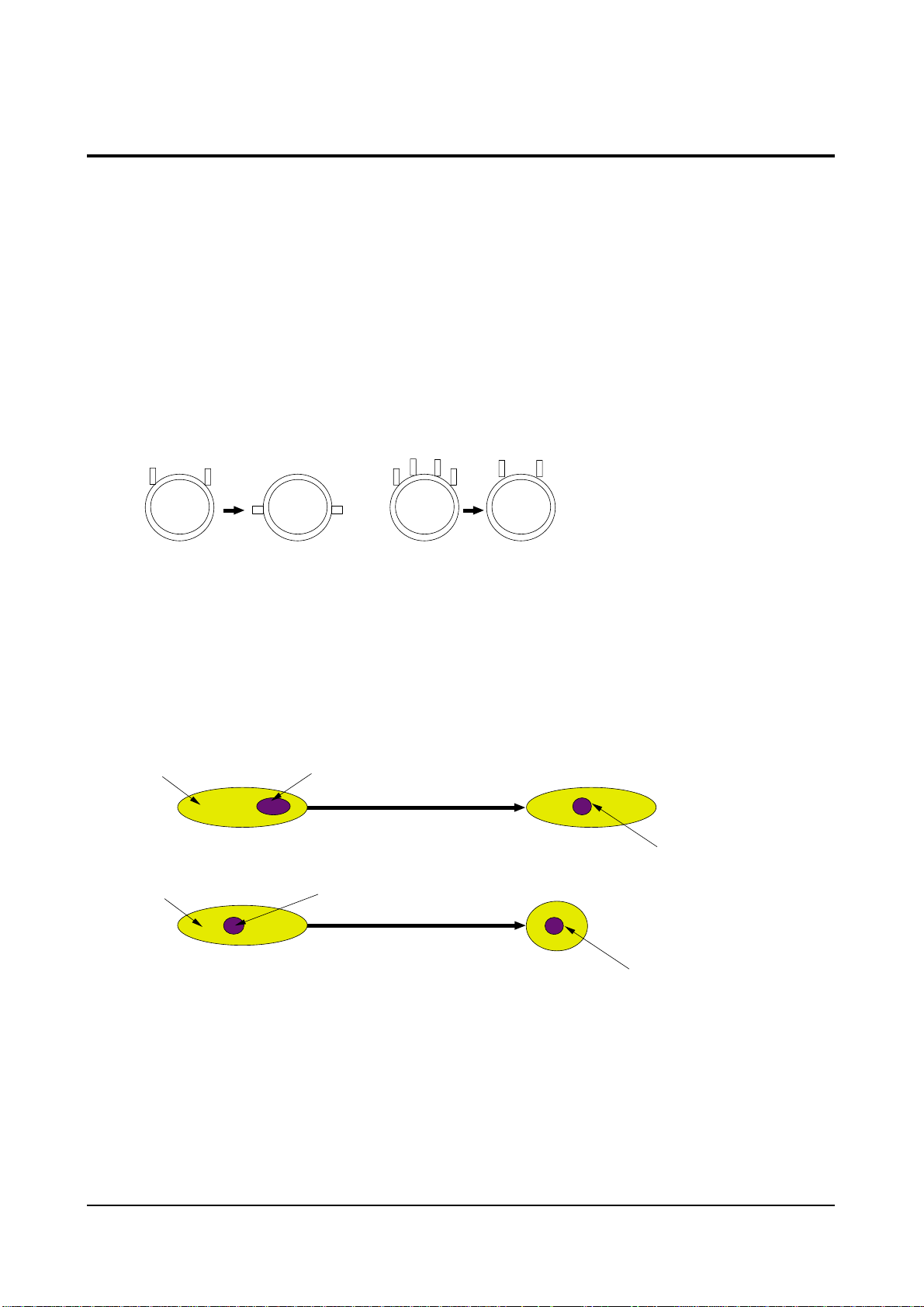
4-3 Beam Alignment
PRECAUTION
1. Input a crosshatch and dot pattern.
2. Select the “STANDARD” video mode.
3. Warm up the TV for at least 10 minutes.
4. Connect an audio oscillator to the pin jig between GT401~GT402 (located on the deflection
PCB) and GND.
5. Determine the ZERO-magnet area (using the beam-alignment CY)
6. Check the squarewave at the point where the focus is misaligned (Use an audio oscillator).
ADJUSTMENT
1. Cover the Red and Blue lenses.
2. Adjust the Green lens as shown in the figures below
3. Adjust the G-Focus until any light around the core disappears.
4. Cover the Green and Blue lenses.
5. Adjust the Red lens using the same method as with the Green lens.
6. Note: The Blue lens is not adjusted because its focus varies little (VM-coil is installed).
7. After the adjustments are completed, disconnect the jig pin connector.
(Creation of CPM Zero Magnet)
(Creation of the 2-pole/4-pole zero magnets)
G-FOCUS
(Varying G-Focus Pack)
G-FOCUS
(When VM 2-Pole Adjustment is completed)
CORE
CORE
Varying the 2-pole of VM
Varying the 4-pole of VM
(Positioning the Core in the Center)
(Adjust until the light around
the core becomes a circle)

Alignment and Adjustments
4-10 Samsung Electronics
4-4 Other Adjustments
4-4-1 Screen Adjustment
1. Warm up the TV for at least 30 minutes.
2. Turn to the Video Mode (No Signal) using a
remote-control.
3. Connect an oscilloscope to RK,GK,BK.
4. Adjust the VR (VR501, VR531, VR561) screen
so that RK, GK, BK pulse is 20Vp-p each.
(Turn the R,G,B VR screen fully
counterclockwise in the area of each flyback
line.)
4-4-2 White Balance Adjustment
1. Select the “STANDARD” video mode.
2. Input 100% white pattern.
3. In the stand-by mode, press the remote-control
keys in the following sequence:
Mute → 1 → 8 → 2 → Power ON
4. Warm up the TV for at least 30 minutes.
5. Input a 10-step signal.
6. R-cut off, B-cut off, and G-cut off by pressing
the Volume +/- keys.
7. Adjust the low light with viewing the dark
side of the screen.
8. Select R-drive, G-drive, and B-drive by
pressing the Volume +/- keys.
9. Adjust the high light with viewing the light
side of the screen.
10. If necessary, redo adjustments 6~9.
11. Press the Menu key to exit.
4-4-3 Sub-Brightness Adjustment
1. Input a sub-brightness adjustment signal.
(TOSHIBA PATTERN)
2. In the stand-by mode, press the remote-control
keys in the following sequence :
Mute - 1 - 8 - 2 - Power ON
3. Select SBT by pressing the Volume +/- keys.
4. Adjust so that the 7th step on the right side of
the screen is not seen (Use the Volume +/keys).
5. Press the Menu key to exit.
4-4-4 High Voltage (31KV) Check
PRECAUTION
1. Input a lion head pattern.
2. Select “STANDARD” video mode.
3. Warm up the TV for at least 10 minutes.
4. Use a 1000:1 probe.
ADJUSTMENT
1. Connect the (+) terminal of the 1000:1 probe to
the high voltage distributor and the (-)
terminal to GND (located on the deflection
board).
2. Adjust VR471 (located on the deflection board)
so that the digital meter indicates
DC 31V ± 0.1V.

Alignment and Adjustments
Samsung Electronics 4-11
4-4-5 F.S. (Fail Safe) Circuit Check
Note : The F.S. Circuit check must be performed
after servicing.
1. Turn on the TV.
2. Select the “STANDARD” video mode.
3. Short GT18, GT17 (located on the
Convergence PCB). Then, both sound and
picture disappear. (Note: Even if the shorted
terminals are removed, both sound and
picture do not appear. This proves the F.S.
circuit is working. )
4. To restore both sound and picture, turn off the
TV and reset it after about 30 seconds.
4-4-6 Static Focus Adjustment
PRECAUTION
1. Select the “STANDARD” video mode.
2. Input a crosshatch pattern.
3. Cover the lenses that are not being adjusted.
4. Connect a convergence jig and read data.
5. Adjust the lens for best focus.
(See Fig, 4-1, next page)
STATIC FOCUS (CONTINUED)
Vary the focus pack VR (Red, Blue) on the
front cabinet. Adjust the TV for best possible
focus around the center of the crosshatch
pattern, without losing overall screen balance.
Figure Crosshatch Pattern
Examine these points together.
4-4-7 Lens Focus Adjustment
PRECAUTIONS
1. Do this adjustment after the static focus
adjustment and the tilt adjustment.
2. Select the “STANDARD” video mode.
(Contrast:64, Brightness:32)
3. Input a crosshatch pattern.
ADJUSTMENT
1. Loosen the lens screws.
2. Cover the two lenses that are not being
adjusted.
3. Adjust the lens, observing the color aberration
vertically and horizontally within 3 blocks of
the center of the crosshatch pattern.
4. When the lens is turned clockwise, the color
aberration will change as follows:
Lens
Color Aberration Change
R Orange - Crimson
G Blue - Red
B Purple - Green
5. Green lens adjustment:
Set the lens at the point where Blue just
changes to Red. If the color aberration is
irregular throughout the picture screen, adjust
the lens to show Red color aberration
(approximately 1~3 mm area) within a 3-block
grid around the horizontal center-line. If the
color aberration is irregular, adjust the lens as
shown in the diagram below. (Accurate
alignment of Green is important for overall
color quality.)
6. Red lens adjustment
Set the Red lens at the point where Orange
becomes Crimson.
7. Blue lens adjustment
Set the Blue lens at the point where Purple
becomes Green.
P
L1
L2
RED ABERRATION
BLUE ABERRATION
L1, L2 < P
_
Fig. 4-1 Crosshatch Pattern.
Fig. 4-2 Color Aberration
Examine these points together

Alignment and Adjustments
4-12 Samsung Electronics
4-4-8 Horizontal Dynamic Focus Adjustment
PRECAUTION
1. Input a crosshatch pattern.
2. Select the “STANDARD” video mode.
3. Warm up the set for at least 10 minutes.
ADJUSTMENT
1. Cover the Red and Blue lenses.
2. Adjust VR491 (located on the convergence
PCB, H-Parabola).
3. Balance the left and right sides of the dynamic
focus lines.

Alignment and Adjustments
Samsung Electronics 4-13
4-5 Screen-Jig
4-5-1 43J5P
4-5-2 43J5P DTV Mode

Alignment and Adjustments
4-14 Samsung Electronics
4-5-3 53J5P
4-5-4 53J5P DTV Mode

Alignment and Adjustments
Samsung Electronics 4-15
4-5-5 61J5P
4-5-6 61J5P DTV

Alignment and Adjustments
4-16 Samsung Electronics
4-5-7 552W
4-5-8 552W DTV Mode

Alignment and Adjustments
Samsung Electronics 4-17
4-6 Remote Control for Servicing (Convergence Mode)
Alignment and Adjustments
4-18 Samsung Electronics
4-6-1 KEY Function
1. R-SELECT
Press to select RED color.
2. G-SELECT
Press to select GREEN color.
3. B-SELECT
Press to select BLUE color.
4. R-MUTE
Press to mute RED color.
5. G-MUTE
Press to mute GREEN color.
6. B-MUTE
Press to mute BLUE color.
7. CANCEL KEY
Press to revert to the previous data during the Convergence
Adjustment.
8. TEST/NORMAL
Press to check TV mode in the Convergence Mode.
9. LINE SHIFT
Press to move a line up/down or left/right.
10. FACTORY DATA SELECT BUTTON
Press to call the factory default values.
11. H/V DIRECTION SELECT BUTTON
Press to switch the cursor direction horizontally or vertically.
12. SAVE BUTTON
After the Convergence Adjustments are completed, press to save data.
13 EXIT BUTTON
After the Convergence adjustments are completed, press to exit to TV mode.

Alignment and Adjustments
Samsung Electronics 4-19
14. MOVE CURSOR FORWARD
Press to move the cursor right or down.
15. MOVE CURSOR REVERSE
Press to move the cursor left or up.
16. CONVERGENCE PICTURE MOVE BUTTON
17. CONVERGENCE PATTERN MOVE BUTTON
Press to move the convergence pattern left ( ) or right ( ) .
18. CONVERGENCE DATAZERO BUTTON
Press to zero the convergence correction data.
19. INITIAL DATA SET BUTTON
Inch (Type)
43” (43J5)
53” (53J5)
61” (614)
55” (552W)
65” (652W)
Model Name
Representative
Model
SVP-43J5P
SVP-53J5P
PCJ614RF
HCJ552W
HCJ652W
Basic Data
Number after entring
the Cg-Mode
5-435 (Press in regular order)
5-535 (Press in regular order)
5-615 (Press in regular order)
5-552 (Press in regular order)
Screen Display
Discription
White Oval on the background
(white circle)
White Oval on the background
(white border)
Used the existing module
(SSVC-1000)
Changes when applying Almighty-Cg, Module (How to extract the basic Cg Data)

Alignment and Adjustments
4-20 Samsung Electronics
4-7 Convergence Adjustment

Alignment and Adjustments
Samsung Electronics 4-21

Alignment and Adjustments
4-22 Samsung Electronics

Alignment and Adjustments
Samsung Electronics 4-23

Alignment and Adjustments
4-24 Samsung Electronics

Alignment and Adjustments
Samsung Electronics 4-25

Alignment and Adjustments
4-26 Samsung Electronics
4-8 PC Mode
4-8-1 TV Setup Mode

Alignment and Adjustments
Samsung Electronics 4-27
4-8-2 Picture Setup Mode
1. Adjust four different modes:VGA3 (VGA), VGA (DOS), VESA (SVGA),
VEAS (XGA).
2). Perform the setup for each PC mode and picture setup.

Alignment and Adjustments
4-28 Samsung Electronics
4-8-3 Picture Setup Mode (computer setup mode only)
1. Adjust four different modes:VGA3 (VGA), VGA (DOS), VESA (SVGA),
VEAS (XGA).
2. Perform the setup for each PC mode and picture setup.

Alignment and Adjustments
Samsung Electronics 4-29
4-9 MICOM and Pins Voltage
4-9-1 Pin Layout
4-9-1(A) PROGRESSIVE
POWER
IR-IN
V-MUTE
3D-SDA
3D-SCL
3D-ENA
IDENT
MODE-SEL
PROTECT
1H-SYNC
SCL 2
SDA 2
CVBS
LOOP FILTER
ANALOG GND
SUB-AFT
KEY1
MAIN-AFT
KEY2
KEY3
ANALOG GND
ANALOG VCC
HALF TONE
OSD B
OSD G
OSD R
1
2
3
4
5
6
7
8
9
10
11
12
13
14
15
16
17
18
19
20
21
22
23
24
25
26
Z
9
0
3
7
1
1
2
P
S
C
52
51
50
49
48
47
46
45
44
43
42
41
40
39
38
37
36
35
34
33
32
31
30
29
28
27
D2
POWER2
BUS-STO P
HOLD
SCL -3
SDA-3
TIMER-LED
S/W-MUTE
D1
AMP-M UTE
3D-RESET
N.C
XTAL GND
VCC
GND
XTAL2
XTAL1
/RESET
N.C
N.C
D3
SCL -1
SDA-1
VSYNC
HSYNC
BL ANK

Alignment and Adjustments
4-30 Samsung Electronics
4-9-1(B) INTERLACE
POWER
IR-IN
V-MUTE
3D-SDA
N.C
N.C
CRTL 3
N.C
PROTECT
N.C
SCL 2
SDA 2
CVBS
LOOP FILTER
ANALOG GND
SUB-AFT
KEY1
MAIN-AFT
KEY2
KEY3
ANALOG GND
ANALOG VCC
HALF TONE
OSD B
OSD G
OSD R
1
2
3
4
5
6
7
8
9
10
11
12
13
14
15
16
17
18
19
20
21
22
23
24
25
26
Z
9
0
3
5
1
1
2
P
S
C
52
51
50
49
48
47
46
45
44
43
42
41
40
39
38
37
36
35
34
33
32
31
30
29
28
27
D2
CTRL 1
BUS-STO P
HOLD
SCL -3
SDA-3
TIMER-LED
S/W-MUTE
D1
AMP-M UTE
CTRL 2
N.C
XTAL GND
VCC
GND
XTAL2
XTAL1
/RESET
N.C
N.C
D3
SCL -1
SDA-1
VSYNC
HSYNC
BL ANK

Alignment and Adjustments
Samsung Electronics 4-31
4-9-2 MICOM Pins
4-9-2(A) PROGRESSIVE
1 POWER POWER ON/OFF RELAY CONTROL H--> L
2 IR IN REMOCON INPUT 5V
3 V-MUTE VIDEO SIGNAL MUTE 3V
4 3D-SDA 3D PHONIC DATA LINE 5V
5 3D-SCL 3D PHONIC CLOCK LINE 5V
6 3D-ENA 3D PHONIC ENABLE LINE 5V
7 IDENT VALID DTV SIGNAL (LOW) 5V
8 MODE-SEL MODE SELECTOR CONTROL 9 PROTECT PROTECT PORT 10 1H-SYNC NORMAL H,V-SYNC 3.5V
11 SCL 2 CLOCK BUS LINE 4.5V
12 SDA 2 DATA BUS LINE 4.5V
13 CVBS CVBS 1.7V
14 LOOP FILTER LOOP FILTER 1.9V
15 ANALOG GND GND GND
16 SUB-AFT SUB AUTO FINE TURNING CONTROL 2.64V
17 KEY 1 KEY SCAN 1 4.84V
18 MAIN-AFT MAIN TUNER AFT 1.9V
19 KEY 2 KEY SCAN 2 20 KEY 3 KEY SCAN 3 21 ANALOG GND GND 22 ANALOG VCC VCC 5V
23 HALF TONE SIGNAL FOR OSC-FREQUENCY OSD CONTROL 24 OSD B ON SCREEN DISPLAY BLUE OUTPUT 25 OSD G ON SCREEN DISPLAY GREEN OUTPUT 26 OSD R ON SCREEN DISPLAY RED OUTPUT -
PIN NO. ITEM FUNCTION OUT VOLT

Alignment and Adjustments
4-32 Samsung Electronics
27 BLANK BLAKING SIGNAL OUTPUT 28 HSYNC HORIZONTAL SYNC INPUT 29 VSYNC VERTICAL SYNC INPUT 30 SDA-1 DATA BUS LINE 4.5V
31 SCL-1 CLOCK BUS LINE 4.12V
32 D3 CONVERGENCE D3 33 N.C N.C 34 N.C N.C 35 /RESET RESET 4.74V
36 XTAL1 XTAL 1 1.72V
37 XTAL2 XTAL 2 2.2V
38 GND GND 39 VCC VCC 5V
40 XTAL GND GND 41 N.C N.C 42 3D-RESET 3D PHONIC RESET 5V
43 AMP-MUTE MAIN AMP MUTE -
44 D1 CONVERGENCE D1 45 S/W-MUTE SWITCH MUTE (NOT USED) 46 TIMER-LED TIMER LED 4.7V
47 SDA-3 DATA BUS LINE 4.6V
48 SCL-3 CLOCK BUS LINE 4.6V
49 HOLD HOLD 4.65V
50 BUS-STOP I
2
C BUS STOP 5V
51 POWER2 PC POWER CONTROL 4.65V
52 D2 CONVERGENCE D2 -
PIN NO. ITEM FUNCTION OUT VOLT

Alignment and Adjustments
Samsung Electronics 4-33
4-9-2(B) INTERLACE
1 POWER POWER ON/OFF RELAY CONTROL H--> L
2 IR IN REMOCON INPUT 5V
3 V-MUTE VIDEO SIGNAL MUTE 3V
4 N.C N.C 5 N.C N.C 6 CRTL 3 CONTROL-3PORT 5V
7 N.C N.C 8 N.C N.C 9 PROTECT PROTECT PORT 10 N.C N.C 11 SCL 2 CLOCK BUS LINE 4.5V
12 SDA 2 DATA BUS LINE 4.5V
13 CVBS CVBS 1.7V
14 LOOP FILTER LOOP FILTER 1.9V
15 ANALOG GND GND GND
16 SUB-AFT SUB AUTO FINE TURNING CONTROL 2.64V
17 KEY 1 KEY SCAN 1 4.84V
18 MAIN-AFT MAIN TUNER AFT 1.9V
19 KEY 2 KEY SCAN 2 20 KEY 3 KEY SCAN 3 21 ANALOG GND GND 22 ANALOG VCC VCC 5V
23 HALF TONE SIGNAL FOR OSC-FREQUENCY OSD CONTROL 24 OSD B ON SCREEN DISPLAY BLUE OUTPUT 25 OSD G ON SCREEN DISPLAY GREEN OUTPUT 26 OSD R ON SCREEN DISPLAY RED OUTPUT -
PIN NO. ITEM FUNCTION OUT VOLT

Alignment and Adjustments
4-34 Samsung Electronics
27 BLANK BLAKING SIGNAL OUTPUT 28 HSYNC HORIZONTAL SYNC INPUT 29 VSYNC VERTICAL SYNC INPUT 30 SDA-1 DATA BUS LINE 4.5V
31 SCL-1 CLOCK BUS LINE 4.12V
32 D3 CONVERGENCE D3 33 N.C N.C 34 N.C N.C 35 /RESET RESET 4.74V
36 XTAL1 XTAL 1 1.72V
37 XTAL2 XTAL 2 2.2V
38 GND GND 39 VCC VCC 5V
40 XTAL GND GND 41 N.C N.C 42 CRTL 2 CONTROL - 2 PORT 5V
43 AMP-MUTE MAIN AMP MUTE 44 D1 CONVERGENCE D1 45 S/W-MUTE SWITCH MUTE (NOT USED) 46 TIMER-LED TIMER LED 4.7V
47 SDA-3 DATA BUS LINE 4.6V
48 SCL-3 CLOCK BUS LINE 4.6V
49 HOLD HOLD 4.65V
50 BUS-STOP I
2
C BUS STOP 5V
51 CRTL 1 CONTROL - 1 PORT 4.65V
52 D2 CONVERGENCE D2 -
PIN NO. ITEM FUNCTION OUT VOLT

Alignment and Adjustments
Samsung Electronics 4-35
4-9-3 Proscan Module (Progressive)
1 DVD-Y DVD-Y INPUT 2.04V
2 GND GND GND
3 CVBS/Y CVBS/Y INPUT 1.76V
4 CIN C-INPUT 2.92V
5 GND GND GND
6 E-Pr/R E-Pr/R INPUT 2.0V
7 E-Y/G E-Y/G INPUT 2.0V
8 E-Pb/B E-Pb/B INPUT 2.0V
9 E-FB FAST BLANKING INPUT 0.25V
10 GND GND GND
11 HS1 1H-SYNC OUT 12 VS1 VS1 OUT 13 GND GND GND
14 SDA-2 SERIAL DATA LINE 2 4.7V
15 SCL-2 SERIAL CLOCK LINE 2 4.8V
16 5V 5V 5V
17 HD H-DRIVE OUT 1.6V
18 H-BLK H-BLANK INPUT 19 VD+ VERTICAL DRIVE (+VOLTAGE) 2.90V
20 VD- VERTICAL DRIVE (-VOLTAGE) 2.95V
21 ABL ABL INPUT 2.15V
22 V-BLK V-BLANKING 23 EW EAST WEST OUT 2.2V
24 N.C N.C 25 GND GND GND
26 V-OUT V-OUT N.C
27 H-OUT H-OUT N.C
28 HC 5V INPUT 29 GND GND GND
30 TEST-Y WHEN CG ADJ PATTERN INPUT -
PIN NO. ITEM FUNCTION OUT VOLT

Alignment and Adjustments
4-36 Samsung Electronics
31 PC-R N.C 32 PC-G N.C 33 PC-B N.C 34 PC-H N.C 35 PC-V N.C 36 GND GND GND
37 OSD-R OSD-R INPUT 38 OSD-G OSD-G INPUT 39 OSD-B OSD-B INPUT 40 YS BLANK(MICOM OUT) 41 YM HALF TONE INPUT 42 V-MUTE VIDEO MUTE (V-CHIP ON) 4.72V
43 GND GND GND
44 9V 9V 9V
45 D-Pr D-Pr INPUT 46 D-Y D-Y INPUT 47 D-Pb D-Pb INPUT 48 PIP-F/B N.C 49 GND GND GND
50 R-OUT R-OUT 51 G-OUT G-OUT 52 B-OUT B-OUT 53 GND GND GND
54 IK IK OUT 3.65V
55 SPOT SPOT OUT 56 GND GND GND
57 VM-Y VM-Y OUT 5.42V
58 VM-MUTE N.C -
PIN NO. ITEM FUNCTION OUT VOLT

Alignment and Adjustments
Samsung Electronics 4-37
4-9-4 Chroma Module (Interlace)
1 N.C N.C 2 GND GND GND
3 CVBS/Y CVBS/Y INPUT 1.76V
4 CIN C-INPUT 2.92V
5 GND GND GND
6 E-Pr/R E-Pr/R INPUT 2.0V
7 E-Y/G E-Y/G INPUT 2.0V
8 E-Pb/B E-Pb/B INPUT 2.0V
9 E-FB FAST BLANKING INPUT 0.25V
10 GND GND GND
11 HS1 1H-SYNC OUT 12 VS1 VS1 OUT 13 GND GND GND
14 SDA-2 SERIAL DATA LINE 2 4.7V
15 SCL-2 SERIAL CLOCK LINE 2 4.8V
16 N.C N.C 17 HD H-DRIVE OUT 1.6V
18 H-BLK H-BLANK INPUT 19 VD+ VERTICAL DRIVE (+VOLTAGE) 2.90V
20 VD- VERTICAL DRIVE (-VOLTAGE) 2.95V
21 ABL ABL INPUT 2.15V
22 V-BLK V-BLANKING 23 EW EAST WEST OUT 2.2V
24 N.C N.C 25 GND GND GND
26 N.C N.C 27 FSC FSC 28 HC 5V INPUT 29 GND GND GND
30 TEST-Y WHEN CG ADJ PATTERN INPUT -
PIN NO. ITEM FUNCTION OUT VOLT

Alignment and Adjustments
4-38 Samsung Electronics
31 N.C N.C 32 N.C N.C 33 N.C N.C 34 CRTL - 3 CRTL - 3 5V
35 CRTL - 1 CRTL - 1 5V
36 GND GND GND
37 OSD-R OSD-R INPUT 38 OSD-G OSD-G INPUT 39 OSD-B OSD-B INPUT 40 YS BLANK(MICOM OUT) 41 YM HALF TONE INPUT 42 V-MUTE VIDEO MUTE (V-CHIP ON) 4.72V
43 GND GND GND
44 9V 9V 9V
45 N.C N.C 46 N.C N.C 47 N.C N.C 48 PIP-F/B N.C 49 GND GND
50 R-OUT R-OUT 51 G-OUT G-OUT 52 B-OUT B-OUT 53 GND GND GND
54 IK IK OUT 3.65V
55 SPOT SPOT OUT 56 GND GND GND
57 VM-Y VM-Y OUT 5.42V
58 CTRL - 2 CTRL - 2 5V
PIN NO. ITEM FUNCTION OUT VOLT

Alignment and Adjustments
Samsung Electronics 4-39
4-9-5 PIP Module
1 GND GND GND
2 TV SUB-V INPUT 2.93V
3 GND GND GND
4 N.C N.C 5 8V 8V INPUT 8V
6 N.C N.C 7 PIP-Pr/R PIP-Pr/R (DVD SIG) OUT 2.02V
8 PIP-Y/G PIP-Y/G (DVD SIG) OUT 2.04V
9 PIP-Pb/B PIP-Pb/B (DVD SIG) OUT 2.02V
10 PIP-FB PIP FAST BLANKING 2.02V
11 12V 12V INPUT 12V
12 PIP-F/B N.C N.C
13 PIP-B DVD-B IN 14 PIP-G DVD-G IN 15 PIP-R DVD-R IN 16 N.C N.C 17 V-SYNC V-SYNC INPUT 18 H-SYNC H-SYNC INPUT 19 SCL SERIAL CLOCK LINE 4.11V
20 SDA SERIAL DATA LINE 4.5V
21 5V 5V INPUT 5V
22 GND GND GND
PIN NO. ITEM FUNCTION OUT VOLT

Alignment and Adjustments
4-40 Samsung Electronics
4-9-6 3D/COMB Module
1 VIDEO MAIN VIDEO INPUT 2.74V
2 GND GND GND
3 9V 9V INPUT 9V
4 GND GND GND
5 SCL SERIAL CLOCK LINE 4.1V
6 SDA SERIAL DATA LINE 4.1V
7 V-3D COPY GUARD REJECT SIGNAL 3.8V
8 5V 5V INPUT 5V
9 Y-OUT MAIN Y OUT 10 GND GND GND
11 C-OUT MAIN C OUT 12 GND GND GND
1 SIF SIF OUT 3.25V
2 9V 9V INPUT 9V
3 GND GND GND
4 IF IF INPUT 4.5V
5 GND GND GND
6 AGC RF AGC IN 5.37V
7 TV-VIDEO TV-VIDEO OUT 8 AFT MAIN AFT INPUT 2V
9 GND GND GND
PIN NO. ITEM FUNCTION OUT VOLT
PIN NO. ITEM FUNCTION OUT VOLT
4-9-7 IF MODULE

Alignment and Adjustments
Samsung Electronics 4-41
4-9-8 F/CONVERTER Module
1 5V 5V INPUT 5V
2 GND GND GND
3 R-IN PC R INPUT 4 G-IN PC G INPUT 5 B-IN PC B INPUT 6 GND GND GND
7 HS PC H-SYNC INPUT 8 VS PC V-SYNC INPUT 9 GND GND GND
10 SDA SERIAL DATA LINE 11 SCL SERIAL CLOCK LINE 12 GND GND GND
13 IR INPUT REMOCON 2.5V
14 GND GND GND
15 R-OUT/Y3 PC Y3 OUT 16 N.C N.C 17 B-OUT/C3 PC C3 OUT -
PIN NO. ITEM FUNCTION OUT VOLT

Alignment and Adjustments
4-42 Samsung Electronics
4-9-9 3D-PHONIC Module
4-9-10 MTS Module

Alignment and Adjustments
Samsung Electronics 4-43
4-9-11 H/V Module
1 12V 12V INPUT 12V
2 GND GND GND
3 HD H-DRIVE INPUT 1.6V
4 V-BLK V-BLANK INPUT 0.72V
5 2H-BLK 2H-BLANK OUT 0.54V
6 GND GND GND
7 PROTECT PROTECT ACTIV H
8 FBT-DC FBT DC FEED BACK 4.87V
9 X-RAY X-RAY PROTECT F/B 2.10V
10 N.C N.C 11 HV-REG HV-REG 3.54V
12 HV-DRIVE HIGH VOLTAGE DRIVE 0.32V
13 H-DRIVE H-DRIVE OUT 25V
14 GND GND GND
15 HEATER HEATER INPUT AC[0.7V]
16 N.C N.C 17 208V 208V INPUT 208V
18 N.C N.C 19 GND GND GND
20 V2 V2 INPUT
21 N.C N.C 22 N.C N.C 23 D-FOCUS DYNAMIC FOCUS OUT 24 N.C N.C 25 N.C N.C 26 SCREEN SCREEN INPUT 1356V
PIN NO. ITEM FUNCTION OUT VOLT

Alignment and Adjustments
4-44 Samsung Electronics
4-9-12 CONV- Module
1 SDA D2 2 SCL D1 3 GND GND GND
4 BV BLUE VERTICAL OUT 5 BH BLUE HORIZONTAL OUT 6 GV GREEN VERTICAL OUT 7 GH GREEN HORIZONTAL OUT 8 RV RED VERTICAL OUT 9 RH RED HORIZONTAL OUT 10 -5.4V -5.4V INPUT -5.4V
11 5.4V 5.4V INPUT +5.4V
12 V-BLK V-BLK INPUT 13 GND GND GND
14 H-BLK H-BLK INPUT 0.52V
15 COMP COMP VIDEO OUTPUT (N.C) N.C
16 IR INPUT REMOCON 3V
17 CTRL CTRL (N.C) N.C
18 D3/SEL D3 0.2V
19 B WHEN TEST PATTERN B OUT 20 G(TEST) WHEN TEST PATTERN G OUT 21 R WHEN TEST PATTERN R OUT 22 SYNC SYNC OUTPUT 4.41V
PIN NO. ITEM FUNCTION OUT VOLT

Troubleshooting
Samsung Electronics 5-1
5. Troubleshooting
5-1 Convergence Misaligned
Normal
Check the
output voltage and waveform
of CN802, CN203 on
the Convergence Board
Abnormal
Check HZ01 out pin
(BV, BH, RV, RH, GV, GH)
Normal
Check the associated
circuitry
Abnormal
Check Convergence
Module
1. Check F802, F855,
F805, F806 on
the SUB Board
2. Check the output
from H-BLK, V-BLK,
D1, D2, D3 on
the Main Board

5-2 No Sound
Troubleshooting
5-2 Samsung Electronics
Check if CN601 is inserted
Normal
Check IC665
output pins 2,4
Abnormal
Check IC665 input pin 3
Normal
Check IC665
mute pin 5
Normal
Abnormal
Insert CN601
(Connector)
Normal
Check Speaker
Abnormal
Check F854 on
the SUB Board
Abnormal
Check the mute circuit
Check IC665
output pins 7,11
Abnormal
Check IC601
input pins 35, 38
Abnormal
Check H006
input pins 15,17
Abnormal
Check ICV01
Input pins 49,51
Abnormal
Normal
Check IC665
Normal
Check Tone Control
Normal
Check the 3D Phonic
circuit
Normal
Check ICV01
Check H003
out Pins 1,2

Troubleshooting
Samsung Electronics 5-3
5-3 No Raster (Sound OK)
Normal
Check High Voltage
Normal
Check CN501
pins 1,3,5
Normal
Check CN501
(Connector)
Abnormal
Check H007
input pins 3,4
Check Heater
Normal
Check IC501, 531,561
Abnormal
Check CN501
(Connector)
Normal
Abnormal
Check CRT PCB pin 1
Normal
Check H401 CN402
HV-REG
Abnormal
Check H401,
IC471
Abnormal
Check H401
Abnormal
Check H401 R437A
Normal
Check CN402 input
pin 12 (HV-DRIVER)
Normal
Check H401
(OUT BLOCK)
Abnormal
Check ICV01 input
pin 48
Abnormal
Check H009
input pin 1
Abnormal
Check ICV01
input pin 50
Abnormal
Check H004
Check H007
Normal
Check ICV01
Normal
Check H009
Normal
Check ICV01

MEMO
5-4 Samsung Electronics

6. Exploded View & Parts List
6-1 PT54925S/SMS
Exploded View & Parts List
Samsung Electronics 6-1
No Code No Description;Specification Q’ty Remark
1 AA64-01708B CABINET-MASK,ETC;DP,54J7PF,ABS,HB,GRAY,L 1
2 AA60-00070C SPACER-SCREEN,OPTION;54J8 SIDE,ABS,-,-,- 2 CWTOP
3 AA60-00070B SPACER-SCREEN,OPTION;54J8 TOP/BOT,ABS,-, 2 CWTOP
4 SUN-SCREEN 1
5 AA67-00116A SCREEN-LENTI;53,-,T1,1123*852,-,-,TINT=1 1
6 TAPE-OPP MASKING 4(M)
7 AA91-00562F ASSY-FRONT,BOT;,HIPS VO G4309,SP700N SAM 1
8 AA91-00770A ASSY-CONTROL;,ABS HB IVORY,BL903P,PT5492 1
9 AA95-00863A ASSY-PCB,A/V FRONT;-,SVP-54J8SR,P51A,-,- 1
9-1 AA95-01315A ASSY PCB CONTROL;DP,P51A,PT54925S,SMS’CL 1
10 AA64-01459C DOOR-AV;54J7,ABS,IVORY,BL903P 1
11 AA64-01402B CABINET-WOOD,BOT;54J9,SDE8326R WOOD,-,- 1
12 AA64-01850B CABINET-BACK,SIDE;DP,54J9,-,-,-,-,V0,-,A 2
13 AA64-01399B CABINET-WOOD,TOP;54J9,WOOD,-,-,-,-,-,SDE 1
14 6006-001094 SCREW-ASS’Y WOOD;WW,HH,+,M7,L32,ZPC(YEL) 8 AWTAWB
15 AA91-00661A ASSY-BRKT,MIRROR;DP,91-00489B 22KG,54J9 4
16 AA60-00091N SPACER-FELT;-,FELT,70X10,-,-,BLK,T1.0,-, 3
17 AA67-00080A MIRROR-BACK;54J8,GLASS,940.5*684.5*674.5 1
18 AA64-01853B CABINET-BACK,TOP;DP,54J8,AA64-01379B 1
19 AA95-00055K ASSY-PCB,CONV AMP;-,SVP-43J4,P51A,-,-,KO 1
20 AA95-01401A ASSY-PCB,SUB;,PT54925S/SMS,P51A,AA95-000 1
21 AA95-00057E ASSY-PCB,TERMINAL;DP,PCL541/542R5S,P51A 1
22 AA94-01636L ASSY PCB MAIN(OPT);PCL541,542R5S/XAA,P51 1
23 AA61-00504B HOLDER-CHASSIS;43,54,62J8,ABS,-,-,-,GRAY 1
24 AA64-01849A CABINET-BACK,BOT;DP,62J8,-,-,-,-,VO,-,AA 1
25 AA64-01395N INLAY-TERMINAL;43,54,62T6,PS SHEET,T0.5, 1
26 AA60-00072B SPACER-COVER,DUST;43,54,62J9,SPONGE 94HF 1
27 AA97-01486A ASSY CRT-(R);,+380MG,P16LNM7RJA,PT54925S 1
28 AA97-01487A ASSY CRT-(G);,+380MG,P16LNM07HKA,PT54925 1
29 AA97-01488A ASSY CRT-(B);,+380MG,P16LNM07BMB,PT54925 1
30 AA26-30006E TRANS-FLYBACK;-,FWZ-50A001B(S),50KV,- 1 D/B
31 6006-001094 SCREW-ASS’Y WOOD;WW,HH,+,M7,L32,ZPC(YEL) 4 CWBBCM
32 AA61-00617A BRACKET-CRT,MAIN;54J7,DP,-,-,-,-,AA61-00 1
33 AA59-00171A MODULE-FOCUS,PACK;SVP-5200,S300-P3,-,-,- 1

7. Electrical Parts List
Electrical Parts List
Samsung Electronics 7-1
ASSY PCB CHASSISPACK
1 * AA93-00132A ASSY PCB CHASSISPACK;,P51A,PT54925S/SMS,
..2 H004 AA95-01279A ASSY-PCB,IF MODULE;,AA95-00527A
...3 CNW201 3711-002707 CONNECTOR-HEADER;NOWALL,9P,1R,2.5mm,ANGL
...3 IC101 1204-001435 IC-IF SYSTEM;LA7565B,DIP,24P,300MIL,PLAS
...3 L102 AA26-00047A TRANS RF;-,7MG,VIF,-,7.7x12.4,39pF,47.
...3 SF01 2904-000288 FILTER-SAW AV;45.75MHz,SIP5K,ST,15.2dB,M
...3 AA41-00234B PCB-IF MODULE;K56B,1L,FR-1,245x245x1.6T, S.N.A
...3 AA99-20097F ASSY-PCB SUB,AUTO; AA95-01279A ,V S.N.A
....4 C101 2202-000797 C-CERAMIC,MLC-AXIAL;10NF,30%,16V,Y5S,TP,
....4 C102 2202-000797 C-CERAMIC,MLC-AXIAL;10NF,30%,16V,Y5S,TP,
....4 C103 2202-000797 C-CERAMIC,MLC-AXIAL;10NF,30%,16V,Y5S,TP,
....4 C104 2202-000797 C-CERAMIC,MLC-AXIAL;10NF,30%,16V,Y5S,TP,
....4 C105 2202-000797 C-CERAMIC,MLC-AXIAL;10NF,30%,16V,Y5S,TP,
....4 C106 2401-000603 C-AL;1uF,20%,50V,GP,TP,5x11,5
....4 C107 2301-000224 C-FILM,PEF;22nF,5%,50V,TP,7.4x3.9x13mm,5
....4 C108 2202-000797 C-CERAMIC,MLC-AXIAL;10NF,30%,16V,Y5S,TP,
....4 C109 2202-000797 C-CERAMIC,MLC-AXIAL;10NF,30%,16V,Y5S,TP,
....4 C110 2401-001625 C-AL;6.8uF,20%,50V,GP,TP,5x11,5
....4 C111 2401-001077 C-AL;330nF,20%,50V,GP,TP,4x7mm,5mm
....4 C113 2201-000986 C-CERAMIC,DISC;0.012nF,5%,50V,NP0,TP,5x3
....4 C114 2401-002183 C-AL;220uF,20%,16V,GP,TP,8x9,5mm
....4 C115 2401-000603 C-AL;1uF,20%,50V,GP,TP,5x11,5
....4 F101 2903-000135 FILTER-CERAMIC;BP,4.5MHz,120KHz,6dB,-,TP
....4 F102 2903-000129 FILTER-CERAMIC;BR,4.5MHz,-,-,-,TP,-
....4 L101 2701-000171 INDUCTOR-AXIAL;330nH,10%,2.5x3.4mm
....4 L104 2701-000191 INDUCTOR-AXIAL;47uH,10%,2.5x3.4mm
....4 L105 2701-000215 INDUCTOR-AXIAL;8.2uH,10%,2.5x3.4mm
....4 R101 2001-000405 R-CARBON;180OHM,5%,1/8W,AA,TP,1.8X3.2M
....4 R102 2001-000221 R-CARBON;1.2KOHM,5%,1/8W,AA,TP,1.8X3.2
....4 R103 2001-000734 R-CARBON;4.7KOHM,5%,1/8W,AA,TP,1.8X3.2
....4 R104 2001-000003 R-CARBON;330ohm,5%,1/8W,AA,TP,1.8x3.2m
....4 R105 2001-000281 R-CARBON;100OHM,5%,1/8W,AA,TP,1.8X3.2M
....4 R106 2001-000273 R-CARBON;100KOHM,5%,1/8W,AA,TP,1.8X3.2
....4 R107 2001-000613 R-CARBON;3.9KOHM,5%,1/8W,AA,TP,1.8X3.2
....4 R108 2001-000786 R-CARBON;47KOHM,5%,1/8W,AA,TP,1.8X3.2M
....4 R109 2001-000009 R-CARBON;20KOHM,5%,1/8W,AA,TP,1.8X3.2M
....4 R110 2001-000563 R-CARBON;27KOHM,5%,1/8W,AA,TP,1.8X3.2M
....4 R111 2001-000837 R-CARBON;51KOHM,5%,1/8W,AA,TP,1.8X3.2M
....4 R112 2001-000362 R-CARBON;150OHM,5%,1/8W,AA,TP,1.8X3.2M
....4 R113 2001-000405 R-CARBON;180OHM,5%,1/8W,AA,TP,1.8X3.2M
....4 R114 2001-000995 R-CARBON;820OHM,5%,1/8W,AA,TP,1.8X3.2M
....4 R117 2001-000613 R-CARBON;3.9KOHM,5%,1/8W,AA,TP,1.8X3.2
....4 R118 2001-001114 R-CARBON(S);270OHM,5%,1/2W,AA,TP,2.4X6.4
....4 R119 2001-000780 R-CARBON;470OHM,5%,1/8W,AA,TP,1.8X3.2M
....4 R120 2001-000290 R-CARBON;10KOHM,5%,1/8W,AA,TP,1.8X3.2M
....4 R121 2001-000281 R-CARBON;100OHM,5%,1/8W,AA,TP,1.8X3.2M
....4 R123 2001-000800 R-CARBON;5.1KOHM,5%,1/8W,AA,TP,1.8X3.2
....4 R130 2001-000613 R-CARBON;3.9KOHM,5%,1/8W,AA,TP,1.8X3.2
....4 TR101 0501-000348 TR-SMALL SIGNAL;KSC1674,NPN,250mW,TO-92,
....4 TR102 0501-000283 TR-SMALL SIGNAL;KSA539,PNP,400mW,TO-92,T
...3 0202-000187 SOLDER-WIRE FLUX;-,RS60S,D1.2,63Sn/37Pb
...3 AA63-00244B SHIELD CASE;ALL MODEL,SPTE ,T0.5,-,-,-,I S.N.A
..2 AA95-00439E ASSY-PCB,CHROMA;-,PCJ522RX/XAA,P51A,-,-,
...3 CN201 3711-003543 CONNECTOR-HEADER;NOWALL,16P,1R,2.54mm,AN
...3 CN202 3711-001283 CONNECTOR-HEADER;NOWALL,14P,1R,2.5mm,ANG
...3 CN203 3711-001283 CONNECTOR-HEADER;NOWALL,14P,1R,2.5mm,ANG
...3 CN204 3711-001283 CONNECTOR-HEADER;NOWALL,14P,1R,2.5mm,ANG
...3 IC201 1204-001207 IC-CHROMA;CXA2095S,DIP,48P,-,PLASTIC,12
...3 IC203 1201-001522 IC-VIDEO AMP;2210,DIP,8P,-,DUAL,-,PLASTI
...3 IC204 0801-000961 IC-CMOS LOGIC;4053,MUTIPLEXER,DIP,16P,30
...3 IC206 0801-000961 IC-CMOS LOGIC;4053,MUTIPLEXER,DIP,16P,30
...3 PCB AA41-00134B PCB-CHROMA;P51A,2L,FR-4,245x245x1.6T,2A, S.N.A
...3 X202 2802-000169 RESONATOR-CERAMIC;500KHz,2KHz,BK,7.0x3.5
...3 AA99-20078A ASSY-PCB SUB,AUTO; AA95-00439E ,V S.N.A
....4 C201 2401-001537 C-AL;47uF,20%,25V,GP,TP,6.3x7mm,5m
....4 C202 2305-000665 C-FILM,MPEF;100nF,5%,63V,TP,7.5x4.0x5.0m
....4 C203 2201-000144 C-CERAMIC,DISC;0.1nF,5%,50V,NP0,TP,8.5x3
....4 C204 2201-000144 C-CERAMIC,DISC;0.1nF,5%,50V,NP0,TP,8.5x3
....4 C205 2301-000445 C-FILM,PEF;4.7nF,5%,50V,TP,5.5x7x3mm,5mm
....4 C206 2401-001914 C-AL;1uF,20%,50V,BP,TP,5x11,5
....4 C207 2301-000235 C-FILM,PEF;3.9nF,5%,50V,TP,6.5x3.0x5.5mm
....4 C208 2401-001333 C-AL;470nF,20%,50V,GP,TP,5x11,5
....4 C209 2401-000660 C-AL;2.2uF,20%,50V,GP,TP,5x11,5
....4 C210 2301-000301 C-FILM,PEF;6.8nF,5%,50V,TP,6.5X5.5X3.0X5
....4 C211 2301-000204 C-FILM,PEF;2.7nF,5%,50V,TP,7.4x3.9x13mm,
....4 C212 2401-001914 C-AL;1uF,20%,50V,BP,TP,5x11,5
....4 C213 2201-000982 C-CERAMIC,DISC;10nF,+80-20%,50V,Y5V,TP,4
....4 C214 2401-001537 C-AL;47uF,20%,25V,GP,TP,6.3x7mm,5m
....4 C216 2309-000138 C-FILM,PE-PPF;100nF,5%,50V,TP,20x16x8.5,
....4 C217 2305-000665 C-FILM,MPEF;100nF,5%,63V,TP,7.5x4.0x5.0m
....4 C218 2305-000665 C-FILM,MPEF;100nF,5%,63V,TP,7.5x4.0x5.0m
....4 C219 2401-000486 C-AL;10uF,20%,50V,GP,TP,6.3x7mm,5
....4 C221 2401-001333 C-AL;470nF,20%,50V,GP,TP,5x11,5
....4 C222 2201-000144 C-CERAMIC,DISC;0.1nF,5%,50V,NP0,TP,8.5x3
....4 C223 2401-001537 C-AL;47uF,20%,25V,GP,TP,6.3x7mm,5m
....4 C224 2401-001537 C-AL;47uF,20%,25V,GP,TP,6.3x7mm,5m
....4 C225 2305-000665 C-FILM,MPEF;100nF,5%,63V,TP,7.5x4.0x5.0m
....4 C226 2305-000665 C-FILM,MPEF;100nF,5%,63V,TP,7.5x4.0x5.0m
....4 C227 2305-000665 C-FILM,MPEF;100nF,5%,63V,TP,7.5x4.0x5.0m
....4 C228 2301-000383 C-FILM,PEF;10nF,5%,50V,TP,6x7x3.2mm,5mm
....4 C229 2301-000383 C-FILM,PEF;10nF,5%,50V,TP,6x7x3.2mm,5mm
....4 C230 2301-000383 C-FILM,PEF;10nF,5%,50V,TP,6x7x3.2mm,5mm
....4 C231 2305-000411 C-FILM,MPEF;470nF,5%,50V,TP,7.3x4.8x5.5m
....4 C232 2305-000411 C-FILM,MPEF;470nF,5%,50V,TP,7.3x4.8x5.5m
....4 C233 2305-000411 C-FILM,MPEF;470nF,5%,50V,TP,7.3x4.8x5.5m
....4 C234 2201-000573 C-CERAMIC,DISC;0.047nF,5%,50V,NP0,TP,5x3
....4 C235 2201-000573 C-CERAMIC,DISC;0.047nF,5%,50V,NP0,TP,5x3
....4 C236 2305-000289 C-FILM,MPEF;220nF,5%,63V,TP,-,5mm
....4 C237 2401-002299 C-AL;4.7uF,20%,50V,GP,TP,5x7,5
....4 C238 2401-001333 C-AL;470nF,20%,50V,GP,TP,5x11,5
....4 C239 2201-000558 C-CERAMIC,DISC;0.47nF,10%,50V,Y5P,TP,5x3
....4 C240 2201-000247 C-CERAMIC,DISC;0.015nF,5%,50V,NP0,TP,5x3
....4 C241 2305-000665 C-FILM,MPEF;100nF,5%,63V,TP,7.5x4.0x5.0m
....4 C242 2401-001537 C-AL;47uF,20%,25V,GP,TP,6.3x7mm,5m
....4 C243 2401-000302 C-AL;100uF,20%,25V,GP,TP,6.3x11,5
....4 C244 2201-000119 C-CERAMIC,DISC;100nF,+80-20%,50V,Y5V,TP,
....4 C245 2401-000404 C-AL;10uF,20%,16V,BP,TP,5x11,5
....4 C254 2401-001537 C-AL;47uF,20%,25V,GP,TP,6.3x7mm,5m
....4 C255 2305-000665 C-FILM,MPEF;100nF,5%,63V,TP,7.5x4.0x5.0m
....4 C256 2305-000665 C-FILM,MPEF;100nF,5%,63V,TP,7.5x4.0x5.0m
....4 C257 2401-001537 C-AL;47uF,20%,25V,GP,TP,6.3x7mm,5m
....4 C260 2301-000383 C-FILM,PEF;10nF,5%,50V,TP,6x7x3.2mm,5mm
....4 C261 2301-000383 C-FILM,PEF;10nF,5%,50V,TP,6x7x3.2mm,5mm
....4 C262 2301-000383 C-FILM,PEF;10nF,5%,50V,TP,6x7x3.2mm,5mm
....4 C263 2401-001537 C-AL;47uF,20%,25V,GP,TP,6.3x7mm,5m
....4 C264 2305-000665 C-FILM,MPEF;100nF,5%,63V,TP,7.5x4.0x5.0m
....4 C265 2301-000383 C-FILM,PEF;10nF,5%,50V,TP,6x7x3.2mm,5mm
....4 C266 2301-000383 C-FILM,PEF;10nF,5%,50V,TP,6x7x3.2mm,5mm
....4 C267 2301-000383 C-FILM,PEF;10nF,5%,50V,TP,6x7x3.2mm,5mm
....4 C268 2201-000573 C-CERAMIC,DISC;0.047nF,5%,50V,NP0,TP,5x3
....4 C269 2201-000573 C-CERAMIC,DISC;0.047nF,5%,50V,NP0,TP,5x3
....4 C270 2401-000480 C-AL;10uF,20%,50V,GP,TP,5x11,5
....4 C271 2305-000411 C-FILM,MPEF;470nF,5%,50V,TP,7.3x4.8x5.5m
....4 C272 2305-000665 C-FILM,MPEF;100nF,5%,63V,TP,7.5x4.0x5.0m
....4 C273 2401-001537 C-AL;47uF,20%,25V,GP,TP,6.3x7mm,5m
....4 C274 2301-000383 C-FILM,PEF;10nF,5%,50V,TP,6x7x3.2mm,5mm
....4 C275 2301-000383 C-FILM,PEF;10nF,5%,50V,TP,6x7x3.2mm,5mm
....4 C276 2301-000383 C-FILM,PEF;10nF,5%,50V,TP,6x7x3.2mm,5mm
....4 C277 2301-000383 C-FILM,PEF;10nF,5%,50V,TP,6x7x3.2mm,5mm
....4 C278 2301-000383 C-FILM,PEF;10nF,5%,50V,TP,6x7x3.2mm,5mm
....4 C279 2301-000383 C-FILM,PEF;10nF,5%,50V,TP,6x7x3.2mm,5mm
....4 D202 0401-000133 DIODE-SWITCHING;RLS4148,100V,200MA,SOD-8
....4 D203 0401-000133 DIODE-SWITCHING;RLS4148,100V,200MA,SOD-8
....4 D204 0401-000133 DIODE-SWITCHING;RLS4148,100V,200MA,SOD-8
Loc. No. Code No. Description ; Specification Remark Loc. No. Code No. Description ; Specification Remark
7-1 PT54925S/SMS

....4 D205 0401-000133 DIODE-SWITCHING;RLS4148,100V,200MA,SOD-8
....4 D206 0401-000133 DIODE-SWITCHING;RLS4148,100V,200MA,SOD-8
....4 D207 0401-000133 DIODE-SWITCHING;RLS4148,100V,200MA,SOD-8
....4 D208 0401-000133 DIODE-SWITCHING;RLS4148,100V,200MA,SOD-8
....4 D209 0401-000133 DIODE-SWITCHING;RLS4148,100V,200MA,SOD-8
....4 D210 0401-000133 DIODE-SWITCHING;RLS4148,100V,200MA,SOD-8
....4 D211 0401-000133 DIODE-SWITCHING;RLS4148,100V,200MA,SOD-8
....4 D212 0401-000133 DIODE-SWITCHING;RLS4148,100V,200MA,SOD-8
....4 D215 0401-000133 DIODE-SWITCHING;RLS4148,100V,200MA,SOD-8
....4 DZ201 0403-000314 DIODE-ZENER;RLZJ9.1B,9.1V,8.80-9.30V,400
....4 DZ202 0403-001117 DIODE-ZENER;RLZ12B,5%,500mW,LL-34,TP
....4 DZ203 0403-001016 DIODE-ZENER;RLZ6.2B,6.2V,5.96-6.27V,400m
....4 DZ204 0403-001016 DIODE-ZENER;RLZ6.2B,6.2V,5.96-6.27V,400m
....4 DZ206 0403-001016 DIODE-ZENER;RLZ6.2B,6.2V,5.96-6.27V,400m
....4 DZ207 0403-001016 DIODE-ZENER;RLZ6.2B,6.2V,5.96-6.27V,400m
....4 DZ208 0403-001117 DIODE-ZENER;RLZ12B,5%,500mW,LL-34,TP
....4 DZ209 0403-001117 DIODE-ZENER;RLZ12B,5%,500mW,LL-34,TP
....4 DZ210 0403-001016 DIODE-ZENER;RLZ6.2B,6.2V,5.96-6.27V,400m
....4 IC205 1204-001214 IC-CHROMA;CXA1839Q,QFP,48P,-,PLASTIC,11
....4 L201 2702-001094 INDUCTOR-RADIAL;10uH,10%,6x4mm
....4 L203 2702-001094 INDUCTOR-RADIAL;10uH,10%,6x4mm
....4 Q201 0501-000389 TR-SMALL SIGNAL;KSC815,NPN,400mW,TO-92,T
....4 Q202 0501-000283 TR-SMALL SIGNAL;KSA539,PNP,400mW,TO-92,T
....4 Q203 0501-000283 TR-SMALL SIGNAL;KSA539,PNP,400mW,TO-92,T
....4 Q204 0501-000389 TR-SMALL SIGNAL;KSC815,NPN,400mW,TO-92,T
....4 Q205 0501-000389 TR-SMALL SIGNAL;KSC815,NPN,400mW,TO-92,T
....4 Q206 0501-000283 TR-SMALL SIGNAL;KSA539,PNP,400mW,TO-92,T
....4 Q207 0501-000283 TR-SMALL SIGNAL;KSA539,PNP,400mW,TO-92,T
....4 Q208 0501-000283 TR-SMALL SIGNAL;KSA539,PNP,400mW,TO-92,T
....4 R201 2007-000029 R-CHIP;0OHM,5%,1/10W,DA,TP,2012
....4 R202 2007-000931 R-CHIP;470OHM,5%,1/10W,DA,TP,2012
....4 R203 2007-000931 R-CHIP;470OHM,5%,1/10W,DA,TP,2012
....4 R204 2007-000210 R-CHIP;1.1KOHM,5%,1/10W,DA,TP,2012
....4 R205 2007-000710 R-CHIP;3.9KOHM,5%,1/10W,DA,TP,2012
....4 R206 2007-000686 R-CHIP;3.3KOHM,5%,1/10W,DA,TP,2012
....4 R207 2007-000468 R-CHIP;1KOHM,5%,1/10W,DA,TP,2012
....4 R208 2007-000931 R-CHIP;470OHM,5%,1/10W,DA,TP,2012
....4 R209 2007-000290 R-CHIP;100OHM,5%,1/10W,DA,TP,2012
....4 R210 2007-000757 R-CHIP;330KOHM,5%,1/10W,DA,TP,2012
....4 R211 2007-000406 R-CHIP;15KOHM,1%,1/10W,DA,TP,2012
....4 R212 2007-001664 R-CHIP;390OHM,1%,1/10W,DA,TP,2012
....4 R213 2007-001071 R-CHIP;6.8KOHM,5%,1/10W,DA,TP,2012
....4 R214 2007-000270 R-CHIP;1.8MOHM,5%,1/10W,DA,TP,2012
....4 R215 2007-000468 R-CHIP;1KOHM,5%,1/10W,DA,TP,2012
....4 R216 2007-000507 R-CHIP;2.49KOHM,1%,1/10W,DA,TP,2012
....4 R217 2007-000300 R-CHIP;10KOHM,5%,1/10W,DA,TP,2012
....4 R219 2007-000290 R-CHIP;100OHM,5%,1/10W,DA,TP,2012
....4 R220 2007-000465 R-CHIP;1KOHM,1%,1/10W,DA,TP,2012
....4 R221 2007-000290 R-CHIP;100OHM,5%,1/10W,DA,TP,2012
....4 R222 2007-000290 R-CHIP;100OHM,5%,1/10W,DA,TP,2012
....4 R223 2007-000468 R-CHIP;1KOHM,5%,1/10W,DA,TP,2012
....4 R224 2007-000290 R-CHIP;100OHM,5%,1/10W,DA,TP,2012
....4 R225 2007-000468 R-CHIP;1KOHM,5%,1/10W,DA,TP,2012
....4 R226 2007-000941 R-CHIP;47KOHM,5%,1/10W,DA,TP,2012
....4 R229 2007-000290 R-CHIP;100OHM,5%,1/10W,DA,TP,2012
....4 R230 2007-000409 R-CHIP;15KOHM,5%,1/10W,DA,TP,2012
....4 R231 2007-000468 R-CHIP;1KOHM,5%,1/10W,DA,TP,2012
....4 R233 2007-000572 R-CHIP;220OHM,5%,1/10W,DA,TP,2012
....4 R234 2007-000468 R-CHIP;1KOHM,5%,1/10W,DA,TP,2012
....4 R235 2007-000290 R-CHIP;100OHM,5%,1/10W,DA,TP,2012
....4 R237 2007-000572 R-CHIP;220OHM,5%,1/10W,DA,TP,2012
....4 R238 2007-000468 R-CHIP;1KOHM,5%,1/10W,DA,TP,2012
....4 R239 2007-000290 R-CHIP;100OHM,5%,1/10W,DA,TP,2012
....4 R241 2007-000572 R-CHIP;220OHM,5%,1/10W,DA,TP,2012
....4 R243 2007-000290 R-CHIP;100OHM,5%,1/10W,DA,TP,2012
....4 R244 2007-000267 R-CHIP;1.8KOHM,5%,1/10W,DA,TP,2012
....4 R245 2007-000267 R-CHIP;1.8KOHM,5%,1/10W,DA,TP,2012
....4 R246 2007-000267 R-CHIP;1.8KOHM,5%,1/10W,DA,TP,2012
....4 R247 2007-000572 R-CHIP;220OHM,5%,1/10W,DA,TP,2012
....4 R248 2007-000572 R-CHIP;220OHM,5%,1/10W,DA,TP,2012
....4 R249 2007-000572 R-CHIP;220OHM,5%,1/10W,DA,TP,2012
....4 R250 2007-000572 R-CHIP;220OHM,5%,1/10W,DA,TP,2012
....4 R251 2007-000572 R-CHIP;220OHM,5%,1/10W,DA,TP,2012
....4 R252 2007-000572 R-CHIP;220OHM,5%,1/10W,DA,TP,2012
....4 R253 2007-000290 R-CHIP;100OHM,5%,1/10W,DA,TP,2012
....4 R254 2007-000457 R-CHIP;18KOHM,5%,1/10W,DA,TP,2012
....4 R255 2007-001653 R-CHIP;1.8KOHM,1%,1/10W,DA,TP,2012
....4 R256 2007-001039 R-CHIP;56KOHM,5%,1/10W,DA,TP,2012
....4 R257 2007-000804 R-CHIP;36KOHM,5%,1/10W,DA,TP,2012
....4 R258 2007-000468 R-CHIP;1KOHM,5%,1/10W,DA,TP,2012
....4 R260 2007-000290 R-CHIP;100OHM,5%,1/10W,DA,TP,2012
....4 R261 2007-000290 R-CHIP;100OHM,5%,1/10W,DA,TP,2012
....4 R262 2007-000290 R-CHIP;100OHM,5%,1/10W,DA,TP,2012
....4 R263 2007-000290 R-CHIP;100OHM,5%,1/10W,DA,TP,2012
....4 R264 2007-000653 R-CHIP;27KOHM,5%,1/10W,DA,TP,2012
....4 R267 2007-000290 R-CHIP;100OHM,5%,1/10W,DA,TP,2012
....4 R268 2007-000653 R-CHIP;27KOHM,5%,1/10W,DA,TP,2012
....4 R270 2007-001001 R-CHIP;510OHM,5%,1/10W,DA,TP,2012
....4 R271 2007-000904 R-CHIP;430OHM,5%,1/10W,DA,TP,2012
....4 R272 2007-000586 R-CHIP;22KOHM,5%,1/10W,DA,TP,2012
....4 R273 2007-000300 R-CHIP;10KOHM,5%,1/10W,DA,TP,2012
....4 R274 2007-000738 R-CHIP;30KOHM,5%,1/10W,DA,TP,2012
....4 R275 2007-000290 R-CHIP;100OHM,5%,1/10W,DA,TP,2012
....4 R276 2007-000290 R-CHIP;100OHM,5%,1/10W,DA,TP,2012
....4 R277 2007-000290 R-CHIP;100OHM,5%,1/10W,DA,TP,2012
....4 R278 2007-000572 R-CHIP;220OHM,5%,1/10W,DA,TP,2012
....4 R279 2007-000572 R-CHIP;220OHM,5%,1/10W,DA,TP,2012
....4 R280 2007-000290 R-CHIP;100OHM,5%,1/10W,DA,TP,2012
....4 R281 2007-000290 R-CHIP;100OHM,5%,1/10W,DA,TP,2012
....4 R282 2007-000290 R-CHIP;100OHM,5%,1/10W,DA,TP,2012
....4 R283 2007-000290 R-CHIP;100OHM,5%,1/10W,DA,TP,2012
....4 R284 2007-000290 R-CHIP;100OHM,5%,1/10W,DA,TP,2012
....4 R285 2007-000290 R-CHIP;100OHM,5%,1/10W,DA,TP,2012
....4 R291 2007-000300 R-CHIP;10KOHM,5%,1/10W,DA,TP,2012
....4 R292 2007-001141 R-CHIP;7.5KOHM,5%,1/10W,DA,TP,2012
....4 R293 2007-000029 R-CHIP;0OHM,5%,1/10W,DA,TP,2012
....4 R295 2007-000029 R-CHIP;0OHM,5%,1/10W,DA,TP,2012
....4 X201 2801-000226 CRYSTAL-UNIT;3.579545MHz,20ppm,28-AAM,15
...3 AA63-00100A SHIELD-CASE;FCC,SPTE,0.5,-,-,-,SCAN-MODU
...3 0202-000187 SOLDER-WIRE FLUX;-,RS60S,D1.2,63Sn/37Pb
...3 2004-002016 R-METAL(S);15Kohm,1%,1/2W,AA,TP,2.5x6.5m
...3 2004-004045 R-METAL(S);390ohm,1%,1/2W,AA,TP,2.5x6.5m
..2 AA95-00531B ASSY-PCB,D-COMB;-,PCJ522R,P51A,-,-,AA95...3 CC01 2401-001496 C-AL;47uF,20%,16V,GP,TP,5x7,5
...3 CC02 2203-000181 C-CERAMIC,CHIP;100nF,+80-20%,25V,Y5V,TP,
...3 CC03 2401-002009 C-AL;100uF,20%,16V,GP,TP,6.3x7,5
...3 CC04 2203-000181 C-CERAMIC,CHIP;100nF,+80-20%,25V,Y5V,TP,
...3 CC05 2401-001496 C-AL;47uF,20%,16V,GP,TP,5x7,5
...3 CC06 2203-000181 C-CERAMIC,CHIP;100nF,+80-20%,25V,Y5V,TP,
...3 CC07 2401-002009 C-AL;100uF,20%,16V,GP,TP,6.3x7,5
...3 CC08 2203-000181 C-CERAMIC,CHIP;100nF,+80-20%,25V,Y5V,TP,
...3 CC10 2401-001496 C-AL;47uF,20%,16V,GP,TP,5x7,5
...3 CC11 2401-001496 C-AL;47uF,20%,16V,GP,TP,5x7,5
...3 CC12 2203-000181 C-CERAMIC,CHIP;100nF,+80-20%,25V,Y5V,TP,
...3 CC15 2203-000361 C-CERAMIC,CHIP;0.15nF,5%,50V,NP0,TP,2012
...3 CC31 2203-000444 C-CERAMIC,CHIP;1nF,10%,50V,X7R,TP,2012,...3 CC32 2203-000260 C-CERAMIC,CHIP;10nF,10%,50V,X7R,TP,2012
...3 CC33 2203-000609 C-CERAMIC,CHIP;22nF,10%,50V,X7R,TP,2012
...3 CC35 2203-000181 C-CERAMIC,CHIP;100nF,+80-20%,25V,Y5V,TP,
...3 CC37 2401-001496 C-AL;47uF,20%,16V,GP,TP,5x7,5
...3 CC38 2203-000181 C-CERAMIC,CHIP;100nF,+80-20%,25V,Y5V,TP,
...3 CC41 2203-000181 C-CERAMIC,CHIP;100nF,+80-20%,25V,Y5V,TP,
...3 CC42 2401-001496 C-AL;47uF,20%,16V,GP,TP,5x7,5
...3 CC43 2203-000181 C-CERAMIC,CHIP;100nF,+80-20%,25V,Y5V,TP,
...3 CC44 2203-000181 C-CERAMIC,CHIP;100nF,+80-20%,25V,Y5V,TP,
...3 CC45 2203-000181 C-CERAMIC,CHIP;100nF,+80-20%,25V,Y5V,TP,
...3 CC46 2401-001496 C-AL;47uF,20%,16V,GP,TP,5x7,5
...3 CC47 2203-000181 C-CERAMIC,CHIP;100nF,+80-20%,25V,Y5V,TP,
...3 CC48 2203-000181 C-CERAMIC,CHIP;100nF,+80-20%,25V,Y5V,TP,
...3 CC49 2203-000181 C-CERAMIC,CHIP;100nF,+80-20%,25V,Y5V,TP,
...3 CC50 2401-001496 C-AL;47uF,20%,16V,GP,TP,5x7,5
...3 CC51 2203-000181 C-CERAMIC,CHIP;100nF,+80-20%,25V,Y5V,TP,
...3 CC52 2203-000181 C-CERAMIC,CHIP;100nF,+80-20%,25V,Y5V,TP,
...3 CC53 2401-001496 C-AL;47uF,20%,16V,GP,TP,5x7,5
...3 CC54 2203-000181 C-CERAMIC,CHIP;100nF,+80-20%,25V,Y5V,TP,
...3 CE07 2203-000239 C-CERAMIC,CHIP;0.1nF,5%,50V,NP0,TP,2012
...3 CE10 2203-000239 C-CERAMIC,CHIP;0.1nF,5%,50V,NP0,TP,2012
...3 CN01 3711-002703 CONNECTOR-HEADER;NOWALL,5P,1R,2.5mm,ANGL
...3 CN02 3711-002703 CONNECTOR-HEADER;NOWALL,5P,1R,2.5mm,ANGL
...3 IC01 1204-001230 IC-SEPARATOR;CXD2043Q,QFP,80P,-,PLASTIC,
...3 LC01 2702-001095 INDUCTOR-RADIAL;18uH,10%,6x4mm
...3 LC02 2702-001095 INDUCTOR-RADIAL;18uH,10%,6x4mm
...3 LC03 2702-001095 INDUCTOR-RADIAL;18uH,10%,6x4mm
...3 LC05 2702-001095 INDUCTOR-RADIAL;18uH,10%,6x4mm
Electrical Parts List
7-2 Samsung Electronics
Loc. No. Code No. Description ; Specification Remark Loc. No. Code No. Description ; Specification Remark

...3 LC06 2702-001095 INDUCTOR-RADIAL;18uH,10%,6x4mm
...3 LC07 2702-001095 INDUCTOR-RADIAL;18uH,10%,6x4mm
...3 LC08 2702-001095 INDUCTOR-RADIAL;18uH,10%,6x4mm
...3 LC09 2702-001095 INDUCTOR-RADIAL;18uH,10%,6x4mm
...3 LC10 2702-001095 INDUCTOR-RADIAL;18uH,10%,6x4mm
...3 LPFC1 2909-001051 FILTER-LC;6MHz,6MHz,0.8dB,TP,5dB/6MHz,3
...3 LPFC2 2909-001051 FILTER-LC;6MHz,6MHz,0.8dB,TP,5dB/6MHz,3
...3 LPFC3 2909-001051 FILTER-LC;6MHz,6MHz,0.8dB,TP,5dB/6MHz,3
...3 PCB AA41-00129A PCB-2D COMB;P51A,2L,FR-4,180X245X1.6T,6A S.N.A
...3 QC01 0501-000280 TR-SMALL SIGNAL;KSA1182,PNP,150mW,SOT-23
...3 QC02 0501-000280 TR-SMALL SIGNAL;KSA1182,PNP,150mW,SOT-23
...3 QC03 0501-000344 TR-SMALL SIGNAL;KSC1623-G,NPN,200mW,SOT...3 QC11 0501-000280 TR-SMALL SIGNAL;KSA1182,PNP,150mW,SOT-23
...3 QC12 0501-000344 TR-SMALL SIGNAL;KSC1623-G,NPN,200mW,SOT...3 QC13 0501-000280 TR-SMALL SIGNAL;KSA1182,PNP,150mW,SOT-23
...3 QC14 0501-000344 TR-SMALL SIGNAL;KSC1623-G,NPN,200mW,SOT...3 QE02 0501-000344 TR-SMALL SIGNAL;KSC1623-G,NPN,200mW,SOT...3 QE03 0501-000280 TR-SMALL SIGNAL;KSA1182,PNP,150mW,SOT-23
...3 RC01 2007-000290 R-CHIP;100OHM,5%,1/10W,DA,TP,2012
...3 RC03 2007-000468 R-CHIP;1KOHM,5%,1/10W,DA,TP,2012
...3 RC04 2007-000468 R-CHIP;1KOHM,5%,1/10W,DA,TP,2012
...3 RC05 2007-000030 R-CHIP;560OHM,5%,1/10W,DA,TP,2012
...3 RC06 2007-000981 R-CHIP;5.6KOHM,5%,1/10W,DA,TP,2012
...3 RC07 2007-001118 R-CHIP;680OHM,5%,1/10W,DA,TP,2012
...3 RC08 2007-000457 R-CHIP;18KOHM,5%,1/10W,DA,TP,2012
...3 RC09 2007-000686 R-CHIP;3.3KOHM,5%,1/10W,DA,TP,2012
...3 RC10 2007-000290 R-CHIP;100OHM,5%,1/10W,DA,TP,2012
...3 RC11 2007-000653 R-CHIP;27KOHM,5%,1/10W,DA,TP,2012
...3 RC44 2007-001039 R-CHIP;56KOHM,5%,1/10W,DA,TP,2012
...3 RC45 2007-001028 R-CHIP;560OHM,1%,1/10W,DA,TP,2012
...3 RC48 2007-001166 R-CHIP;75OHM,5%,1/10W,DA,TP,2012
...3 RC49 2007-000468 R-CHIP;1KOHM,5%,1/10W,DA,TP,2012
...3 RC51 2007-000468 R-CHIP;1KOHM,5%,1/10W,DA,TP,2012
...3 RC52 2007-000686 R-CHIP;3.3KOHM,5%,1/10W,DA,TP,2012
...3 RC53 2007-000686 R-CHIP;3.3KOHM,5%,1/10W,DA,TP,2012
...3 RC54 2007-001201 R-CHIP;820OHM,5%,1/10W,DA,TP,2012
...3 RC55 2007-000468 R-CHIP;1KOHM,5%,1/10W,DA,TP,2012
...3 RC61 2007-000642 R-CHIP;270OHM,5%,1/10W,DA,TP,2012
...3 RC62 2007-000290 R-CHIP;100OHM,5%,1/10W,DA,TP,2012
...3 RC63 2007-000493 R-CHIP;2.2KOHM,5%,1/10W,DA,TP,2012
...3 RC64 2007-000030 R-CHIP;560OHM,5%,1/10W,DA,TP,2012
...3 RC65 2007-000981 R-CHIP;5.6KOHM,5%,1/10W,DA,TP,2012
...3 RC66 2007-000468 R-CHIP;1KOHM,5%,1/10W,DA,TP,2012
...3 RC67 2007-001166 R-CHIP;75OHM,5%,1/10W,DA,TP,2012
...3 RC71 2007-000607 R-CHIP;240OHM,5%,1/10W,DA,TP,2012
...3 RC72 2007-000290 R-CHIP;100OHM,5%,1/10W,DA,TP,2012
...3 RC73 2007-000493 R-CHIP;2.2KOHM,5%,1/10W,DA,TP,2012
...3 RC74 2007-000030 R-CHIP;560OHM,5%,1/10W,DA,TP,2012
...3 RC75 2007-000981 R-CHIP;5.6KOHM,5%,1/10W,DA,TP,2012
...3 RC76 2007-000468 R-CHIP;1KOHM,5%,1/10W,DA,TP,2012
...3 RC77 2007-001166 R-CHIP;75OHM,5%,1/10W,DA,TP,2012
...3 RE11 2007-000586 R-CHIP;22KOHM,5%,1/10W,DA,TP,2012
...3 RE12 2007-000300 R-CHIP;10KOHM,5%,1/10W,DA,TP,2012
...3 RE13 2007-000931 R-CHIP;470OHM,5%,1/10W,DA,TP,2012
...3 RE14 2007-000642 R-CHIP;270OHM,5%,1/10W,DA,TP,2012
...3 RE15 2007-000904 R-CHIP;430OHM,5%,1/10W,DA,TP,2012
...3 RE16 2007-000468 R-CHIP;1KOHM,5%,1/10W,DA,TP,2012
...3 RE41 2007-000029 R-CHIP;0OHM,5%,1/10W,DA,TP,2012
...3 RE43 2007-000029 R-CHIP;0OHM,5%,1/10W,DA,TP,2012
...3 AA63-40014A SHIELD-CASE,T;-,SPTE,T0.5,-,-,-,SCT51A S.N.A
...3 0202-000187 SOLDER-WIRE FLUX;-,RS60S,D1.2,63Sn/37Pb
..2 AA95-00649A ASSY-PCB,PIP;-,-,P51A ALL,-,-,...3 CNP01 3711-002705 CONNECTOR-HEADER;NOWALL,7P,1R,2.5mm,ANGL
...3 CNP02 3711-002702 CONNECTOR-HEADER;NOWALL,4P,1R,2.5mm,ANGL
...3 CNP03 3711-002703 CONNECTOR-HEADER;NOWALL,5P,1R,2.5mm,ANGL
...3 CNP04 3711-002704 CONNECTOR-HEADER;NOWALL,6P,1R,2.5mm,ANGL
...3 H001 AA61-10068A BRACKET-PCB;M2160,SPTE,T0.3,-,-,-,...3 XP01 2801-004019 CRYSTAL-UNIT;20.25MHz,30ppm,28-AAM,13pF,
...3 AA99-20073N ASSY-PCB SUB,AUTO; AA95-00649A ,V S.N.A
....4 CP01 2203-000274 C-CERAMIC,CHIP;0.01nF,0.25pF,50V,NP0,TP,
....4 CP02 2203-000274 C-CERAMIC,CHIP;0.01nF,0.25pF,50V,NP0,TP,
....4 CP03 2203-000408 C-CERAMIC,CHIP;0.18nF,5%,50V,NP0,TP,2012
....4 CP05 2401-002144 C-AL;47uF,20%,16V,GP,TP,5x11,5
....4 CP06 2203-000260 C-CERAMIC,CHIP;10nF,10%,50V,X7R,TP,2012
....4 CP07 2401-002144 C-AL;47uF,20%,16V,GP,TP,5x11,5
....4 CP08 2203-000260 C-CERAMIC,CHIP;10nF,10%,50V,X7R,TP,2012
....4 CP09 2401-002144 C-AL;47uF,20%,16V,GP,TP,5x11,5
....4 CP10 2203-000260 C-CERAMIC,CHIP;10nF,10%,50V,X7R,TP,2012
....4 CP11 2203-005384 C-CERAMIC,CHIP;4700nF,+80-20%,10V,Y5V,TP
....4 CP12 2203-000181 C-CERAMIC,CHIP;100nF,+80-20%,25V,Y5V,TP,
....4 CP13 2203-005384 C-CERAMIC,CHIP;4700nF,+80-20%,10V,Y5V,TP
....4 CP14 2203-000181 C-CERAMIC,CHIP;100nF,+80-20%,25V,Y5V,TP,
....4 CP15 2203-005384 C-CERAMIC,CHIP;4700nF,+80-20%,10V,Y5V,TP
....4 CP16 2203-000181 C-CERAMIC,CHIP;100nF,+80-20%,25V,Y5V,TP,
....4 CP17 2203-001245 C-CERAMIC,CHIP;0.082nF,5%,50V,NP0,TP,201
....4 CP18 2203-000260 C-CERAMIC,CHIP;10nF,10%,50V,X7R,TP,2012
....4 CP19 2401-002235 C-AL;10uF,20%,16V,GP,TP,5x11mm,5mm
....4 CP20 2203-000260 C-CERAMIC,CHIP;10nF,10%,50V,X7R,TP,2012
....4 CP21 2401-001840 C-AL;100uF,20%,16V,GP,TP,6.3x11,5
....4 CP22 2203-000181 C-CERAMIC,CHIP;100nF,+80-20%,25V,Y5V,TP,
....4 CP23 2203-000260 C-CERAMIC,CHIP;10nF,10%,50V,X7R,TP,2012
....4 CP24 2401-000660 C-AL;2.2uF,20%,50V,GP,TP,5x11,5
....4 CP25 2203-000181 C-CERAMIC,CHIP;100nF,+80-20%,25V,Y5V,TP,
....4 CP26 2203-000260 C-CERAMIC,CHIP;10nF,10%,50V,X7R,TP,2012
....4 CP27 2401-000660 C-AL;2.2uF,20%,50V,GP,TP,5x11,5
....4 CP28 2203-000181 C-CERAMIC,CHIP;100nF,+80-20%,25V,Y5V,TP,
....4 ICP01 1204-001668 IC-PICTURE PROCESS;SDA9488X,SOP,28P,300M
....4 ICP02 1203-001419 IC-VOLTAGE REGULATOR;4931,TO-252,3P,6.6x
....4 LP01 2901-000297 FILTER-EMI ON BOARD;-,3A,-,-,3.5x5,TP,-
....4 LP02 2901-000297 FILTER-EMI ON BOARD;-,3A,-,-,3.5x5,TP,-
....4 LP03 2901-000297 FILTER-EMI ON BOARD;-,3A,-,-,3.5x5,TP,-
....4 LP04 2901-000297 FILTER-EMI ON BOARD;-,3A,-,-,3.5x5,TP,-
....4 PCB AA41-00278B PCB-PIP MODULE;ALL MODEL,CEM-3,2L,B,1.6T S.N.A
....4 QP01 0501-000344 TR-SMALL SIGNAL;KSC1623-G,NPN,200mW,SOT-
....4 QP02 0501-000344 TR-SMALL SIGNAL;KSC1623-G,NPN,200mW,SOT-
....4 QP03 0501-000344 TR-SMALL SIGNAL;KSC1623-G,NPN,200mW,SOT-
....4 QP04 0501-000344 TR-SMALL SIGNAL;KSC1623-G,NPN,200mW,SOT-
....4 RP01 2007-000468 R-CHIP;1KOHM,5%,1/10W,DA,TP,2012
....4 RP02 2007-000931 R-CHIP;470OHM,5%,1/10W,DA,TP,2012
....4 RP03 2007-000290 R-CHIP;100OHM,5%,1/10W,DA,TP,2012
....4 RP04 2007-000290 R-CHIP;100OHM,5%,1/10W,DA,TP,2012
....4 RP05 2007-000290 R-CHIP;100OHM,5%,1/10W,DA,TP,2012
....4 RP06 2007-000290 R-CHIP;100OHM,5%,1/10W,DA,TP,2012
....4 RP07 2007-000300 R-CHIP;10KOHM,5%,1/10W,DA,TP,2012
....4 RP08 2007-001166 R-CHIP;75OHM,5%,1/10W,DA,TP,2012
....4 RP09 2007-000941 R-CHIP;47KOHM,5%,1/10W,DA,TP,2012
....4 RP10 2007-000941 R-CHIP;47KOHM,5%,1/10W,DA,TP,2012
....4 RP11 2007-000931 R-CHIP;470OHM,5%,1/10W,DA,TP,2012
....4 RP12 2007-001166 R-CHIP;75OHM,5%,1/10W,DA,TP,2012
....4 RP13 2007-000941 R-CHIP;47KOHM,5%,1/10W,DA,TP,2012
....4 RP14 2007-000941 R-CHIP;47KOHM,5%,1/10W,DA,TP,2012
....4 RP15 2007-000931 R-CHIP;470OHM,5%,1/10W,DA,TP,2012
....4 RP16 2007-001166 R-CHIP;75OHM,5%,1/10W,DA,TP,2012
....4 RP17 2007-000941 R-CHIP;47KOHM,5%,1/10W,DA,TP,2012
....4 RP18 2007-000941 R-CHIP;47KOHM,5%,1/10W,DA,TP,2012
....4 RP19 2007-000931 R-CHIP;470OHM,5%,1/10W,DA,TP,2012
....4 RP21 2007-000300 R-CHIP;10KOHM,5%,1/10W,DA,TP,2012
....4 RP22 2007-000290 R-CHIP;100OHM,5%,1/10W,DA,TP,2012
....4 RP23 2007-000029 R-CHIP;0OHM,5%,1/10W,DA,TP,2012
....4 RP24 2007-000029 R-CHIP;0OHM,5%,1/10W,DA,TP,2012
....4 RP26 2007-000029 R-CHIP;0OHM,5%,1/10W,DA,TP,2012
....4 RP28 2007-000029 R-CHIP;0OHM,5%,1/10W,DA,TP,2012
....4 RP30 2007-000607 R-CHIP;240OHM,5%,1/10W,DA,TP,2012
....4 RP31 2007-000572 R-CHIP;220OHM,5%,1/10W,DA,TP,2012
....4 RP32 2007-001201 R-CHIP;820OHM,5%,1/10W,DA,TP,2012
....4 RP48 2007-000468 R-CHIP;1KOHM,5%,1/10W,DA,TP,2012
....4 RP49 2007-000964 R-CHIP;5.1KOHM,5%,1/10W,DA,TP,2012
....4 RP50 2007-000468 R-CHIP;1KOHM,5%,1/10W,DA,TP,2012
....4 RP51 2007-000844 R-CHIP;3KOHM,5%,1/10W,DA,TP,2012
..2 AA95-01113C ASSY-PCB,CONV MDL;,SVP-54J7P,P51A
...3 CN101 3711-002709 CONNECTOR-HEADER;NOWALL,12P,1R,2.5mm,ANG
...3 CN102 3711-002709 CONNECTOR-HEADER;NOWALL,12P,1R,2.5mm,ANG
...3 AA63-00396B SHIELD CASE-TOP;PRJT,P54A,SPTE,T0.5,-,-, S.N.A
...3 AA63-00397B SHIELD CASE-BOT;PRJT,P54A,SPTE,T0.5,-,-, S.N.A
...3 AA99-20099M ASSY-PCB SUB,AUTO; AA95-01113C ,V S.N.A
....4 C101 2402-001042 C-AL,SMD;100uF,20%,16V,GP,TP,6.6x6.6x5
....4 C102 2402-001042 C-AL,SMD;100uF,20%,16V,GP,TP,6.6x6.6x5
....4 C103 2402-001042 C-AL,SMD;100uF,20%,16V,GP,TP,6.6x6.6x5
....4 C104 2203-000181 C-CERAMIC,CHIP;100nF,+80-20%,25V,Y5V,TP,
....4 C105 2203-000851 C-CERAMIC,CHIP;0.039nF,5%,50V,NP0,TP,160
....4 C106 2203-000181 C-CERAMIC,CHIP;100nF,+80-20%,25V,Y5V,TP,
....4 C107 2203-000715 C-CERAMIC,CHIP;3.3nF,10%,50V,X7R,TP,1608
....4 C108 2402-000170 C-AL,SMD;1uF,20%,50V,GP,TP,4.3x4.3x5.4
....4 C109 2203-000181 C-CERAMIC,CHIP;100nF,+80-20%,25V,Y5V,TP,
Electrical Parts List
Samsung Electronics 7-3
Loc. No. Code No. Description ; Specification Remark Loc. No. Code No. Description ; Specification Remark

....4 C110 2203-000440 C-CERAMIC,CHIP;1nF,10%,50V,X7R,TP,1608,-
....4 C111 2203-000181 C-CERAMIC,CHIP;100nF,+80-20%,25V,Y5V,TP,
....4 C112 2203-000681 C-CERAMIC,CHIP;0.027nF,5%,50V,NP0,TP,160
....4 C113 2203-000681 C-CERAMIC,CHIP;0.027nF,5%,50V,NP0,TP,160
....4 C114 2203-000181 C-CERAMIC,CHIP;100nF,+80-20%,25V,Y5V,TP,
....4 C115 2203-000181 C-CERAMIC,CHIP;100nF,+80-20%,25V,Y5V,TP,
....4 C116 2203-000181 C-CERAMIC,CHIP;100nF,+80-20%,25V,Y5V,TP,
....4 C117 2203-000181 C-CERAMIC,CHIP;100nF,+80-20%,25V,Y5V,TP,
....4 C118 2203-000181 C-CERAMIC,CHIP;100nF,+80-20%,25V,Y5V,TP,
....4 C119 2203-000181 C-CERAMIC,CHIP;100nF,+80-20%,25V,Y5V,TP,
....4 C120 2203-000181 C-CERAMIC,CHIP;100nF,+80-20%,25V,Y5V,TP,
....4 C121 2203-000181 C-CERAMIC,CHIP;100nF,+80-20%,25V,Y5V,TP,
....4 C122 2203-000181 C-CERAMIC,CHIP;100nF,+80-20%,25V,Y5V,TP,
....4 C123 2203-000181 C-CERAMIC,CHIP;100nF,+80-20%,25V,Y5V,TP,
....4 C124 2203-000181 C-CERAMIC,CHIP;100nF,+80-20%,25V,Y5V,TP,
....4 C125 2203-000181 C-CERAMIC,CHIP;100nF,+80-20%,25V,Y5V,TP,
....4 C126 2203-000181 C-CERAMIC,CHIP;100nF,+80-20%,25V,Y5V,TP,
....4 C127 2203-000181 C-CERAMIC,CHIP;100nF,+80-20%,25V,Y5V,TP,
....4 C128 2203-000181 C-CERAMIC,CHIP;100nF,+80-20%,25V,Y5V,TP,
....4 C129 2203-000181 C-CERAMIC,CHIP;100nF,+80-20%,25V,Y5V,TP,
....4 C130 2203-000181 C-CERAMIC,CHIP;100nF,+80-20%,25V,Y5V,TP,
....4 C131 2203-000181 C-CERAMIC,CHIP;100nF,+80-20%,25V,Y5V,TP,
....4 C132 2203-000405 C-CERAMIC,CHIP;0.18nF,5%,50V,NP0,TP,1608
....4 C133 2404-000123 C-TA,CHIP;10uF,20%,16V,-,TP,6032,2.9mm
....4 C134 2203-000181 C-CERAMIC,CHIP;100nF,+80-20%,25V,Y5V,TP,
....4 C135 2203-000715 C-CERAMIC,CHIP;3.3nF,10%,50V,X7R,TP,1608
....4 C136 2203-000181 C-CERAMIC,CHIP;100nF,+80-20%,25V,Y5V,TP,
....4 C137 2203-000715 C-CERAMIC,CHIP;3.3nF,10%,50V,X7R,TP,1608
....4 C138 2203-000405 C-CERAMIC,CHIP;0.18nF,5%,50V,NP0,TP,1608
....4 C139 2203-000181 C-CERAMIC,CHIP;100nF,+80-20%,25V,Y5V,TP,
....4 C140 2404-000123 C-TA,CHIP;10uF,20%,16V,-,TP,6032,2.9mm
....4 C141 2203-000405 C-CERAMIC,CHIP;0.18nF,5%,50V,NP0,TP,1608
....4 C142 2404-000123 C-TA,CHIP;10uF,20%,16V,-,TP,6032,2.9mm
....4 C143 2203-000181 C-CERAMIC,CHIP;100nF,+80-20%,25V,Y5V,TP,
....4 C144 2203-000715 C-CERAMIC,CHIP;3.3nF,10%,50V,X7R,TP,1608
....4 C145 2203-000181 C-CERAMIC,CHIP;100nF,+80-20%,25V,Y5V,TP,
....4 C146 2203-000715 C-CERAMIC,CHIP;3.3nF,10%,50V,X7R,TP,1608
....4 C147 2203-000405 C-CERAMIC,CHIP;0.18nF,5%,50V,NP0,TP,1608
....4 C148 2404-000123 C-TA,CHIP;10uF,20%,16V,-,TP,6032,2.9mm
....4 C149 2203-000181 C-CERAMIC,CHIP;100nF,+80-20%,25V,Y5V,TP,
....4 C150 2203-000181 C-CERAMIC,CHIP;100nF,+80-20%,25V,Y5V,TP,
....4 C151 2203-000405 C-CERAMIC,CHIP;0.18nF,5%,50V,NP0,TP,1608
....4 C152 2404-000123 C-TA,CHIP;10uF,20%,16V,-,TP,6032,2.9mm
....4 C153 2203-000181 C-CERAMIC,CHIP;100nF,+80-20%,25V,Y5V,TP,
....4 C154 2203-000715 C-CERAMIC,CHIP;3.3nF,10%,50V,X7R,TP,1608
....4 C155 2203-000181 C-CERAMIC,CHIP;100nF,+80-20%,25V,Y5V,TP,
....4 C156 2203-000715 C-CERAMIC,CHIP;3.3nF,10%,50V,X7R,TP,1608
....4 C157 2203-000405 C-CERAMIC,CHIP;0.18nF,5%,50V,NP0,TP,1608
....4 C158 2404-000123 C-TA,CHIP;10uF,20%,16V,-,TP,6032,2.9mm
....4 C159 2203-000181 C-CERAMIC,CHIP;100nF,+80-20%,25V,Y5V,TP,
....4 C160 2203-000181 C-CERAMIC,CHIP;100nF,+80-20%,25V,Y5V,TP,
....4 C161 2402-001042 C-AL,SMD;100uF,20%,16V,GP,TP,6.6x6.6x5
....4 C162 2402-001042 C-AL,SMD;100uF,20%,16V,GP,TP,6.6x6.6x5
....4 C163 2305-000289 C-FILM,MPEF;220nF,5%,63V,TP,-,5mm
....4 C164 2402-000173 C-AL,SMD;4.7uF,20%,35V,GP,TP,4.3x4.3x5
....4 C165 2203-000181 C-CERAMIC,CHIP;100nF,+80-20%,25V,Y5V,TP,
....4 C166 2203-000181 C-CERAMIC,CHIP;100nF,+80-20%,25V,Y5V,TP,
....4 C167 2404-000123 C-TA,CHIP;10uF,20%,16V,-,TP,6032,2.9mm
....4 C168 2203-000181 C-CERAMIC,CHIP;100nF,+80-20%,25V,Y5V,TP,
....4 C169 2203-000181 C-CERAMIC,CHIP;100nF,+80-20%,25V,Y5V,TP,
....4 C170 2203-000181 C-CERAMIC,CHIP;100nF,+80-20%,25V,Y5V,TP,
....4 C172 2402-001042 C-AL,SMD;100uF,20%,16V,GP,TP,6.6x6.6x5
....4 C173 2402-001042 C-AL,SMD;100uF,20%,16V,GP,TP,6.6x6.6x5
....4 C174 2402-001042 C-AL,SMD;100uF,20%,16V,GP,TP,6.6x6.6x5
....4 C201 2203-000405 C-CERAMIC,CHIP;0.18nF,5%,50V,NP0,TP,1608
....4 C202 2203-000405 C-CERAMIC,CHIP;0.18nF,5%,50V,NP0,TP,1608
....4 C203 2203-000405 C-CERAMIC,CHIP;0.18nF,5%,50V,NP0,TP,1608
....4 C204 2203-000405 C-CERAMIC,CHIP;0.18nF,5%,50V,NP0,TP,1608
....4 C205 2203-000405 C-CERAMIC,CHIP;0.18nF,5%,50V,NP0,TP,1608
....4 C206 2203-000405 C-CERAMIC,CHIP;0.18nF,5%,50V,NP0,TP,1608
....4 C301 2402-001042 C-AL,SMD;100uF,20%,16V,GP,TP,6.6x6.6x5
....4 D101 0401-000160 DIODE-SWITCHING;ISS314,30V,100mA,USC,TP
....4 D102 0401-000160 DIODE-SWITCHING;ISS314,30V,100mA,USC,TP
....4 DZ101 0403-001016 DIODE-ZENER;RLZ6.2B,6.2V,5.96-6.27V,400m
....4 DZ102 0403-001016 DIODE-ZENER;RLZ6.2B,6.2V,5.96-6.27V,400m
....4 DZ105 0403-001016 DIODE-ZENER;RLZ6.2B,6.2V,5.96-6.27V,400m
....4 DZ106 0403-001016 DIODE-ZENER;RLZ6.2B,6.2V,5.96-6.27V,400m
....4 DZ107 0403-001016 DIODE-ZENER;RLZ6.2B,6.2V,5.96-6.27V,400m
....4 DZ108 0403-001016 DIODE-ZENER;RLZ6.2B,6.2V,5.96-6.27V,400m
....4 DZ109 0403-001016 DIODE-ZENER;RLZ6.2B,6.2V,5.96-6.27V,400m
....4 DZ110 0403-001016 DIODE-ZENER;RLZ6.2B,6.2V,5.96-6.27V,400m
....4 DZ111 0403-001016 DIODE-ZENER;RLZ6.2B,6.2V,5.96-6.27V,400m
....4 DZ112 0403-001016 DIODE-ZENER;RLZ6.2B,6.2V,5.96-6.27V,400m
....4 DZ113 0403-001016 DIODE-ZENER;RLZ6.2B,6.2V,5.96-6.27V,400m
....4 DZ114 0403-001016 DIODE-ZENER;RLZ6.2B,6.2V,5.96-6.27V,400m
....4 DZ115 0403-001016 DIODE-ZENER;RLZ6.2B,6.2V,5.96-6.27V,400m
....4 DZ116 0403-001016 DIODE-ZENER;RLZ6.2B,6.2V,5.96-6.27V,400m
....4 EF101 2901-000229 FILTER-EMI SMD;50V,0.3A,-,22000pF,4.5x3.
....4 EF102 2901-000229 FILTER-EMI SMD;50V,0.3A,-,22000pF,4.5x3.
....4 EF105 2901-000226 FILTER-EMI SMD;25V,0.3A,-,100pF,3.2x1.25
....4 EF106 2901-000226 FILTER-EMI SMD;25V,0.3A,-,100pF,3.2x1.25
....4 EF107 2901-000226 FILTER-EMI SMD;25V,0.3A,-,100pF,3.2x1.25
....4 EF108 2901-000226 FILTER-EMI SMD;25V,0.3A,-,100pF,3.2x1.25
....4 EF109 2901-000226 FILTER-EMI SMD;25V,0.3A,-,100pF,3.2x1.25
....4 EF110 2901-000226 FILTER-EMI SMD;25V,0.3A,-,100pF,3.2x1.25
....4 EF111 2901-000226 FILTER-EMI SMD;25V,0.3A,-,100pF,3.2x1.25
....4 EF112 2901-000226 FILTER-EMI SMD;25V,0.3A,-,100pF,3.2x1.25
....4 EF113 2901-000226 FILTER-EMI SMD;25V,0.3A,-,100pF,3.2x1.25
....4 EF114 2901-000226 FILTER-EMI SMD;25V,0.3A,-,100pF,3.2x1.25
....4 EF115 2901-000226 FILTER-EMI SMD;25V,0.3A,-,100pF,3.2x1.25
....4 EF116 2901-000226 FILTER-EMI SMD;25V,0.3A,-,100pF,3.2x1.25
....4 IC101 AA13-00071A IC-ASIC;-,SDC91,QFP,208P,CONV CONTROL
....4 IC102 0801-001043 IC-CMOS LOGIC;74HC4046,PHASE-LOCKED-LOOP
....4 IC103 AA09-00032A IC-MCU;TSC87251G2D-OTP,TSC87251G2D-O
....4 IC104 1103-001167 IC-EEPROM;28C64,8KX8BIT,TSOP,28P,-,120N
....4 IC105 1201-001520 IC-VIDEO AMP;EL2250CS,SOIC,8P,150MIL,DUA
....4 IC106 1201-001504 IC-OP AMP;072,SOP,8P,150MIL,DUAL,-,PLAS
....4 IC107 1201-001504 IC-OP AMP;072,SOP,8P,150MIL,DUAL,-,PLAS
....4 IC108 1201-001504 IC-OP AMP;072,SOP,8P,150MIL,DUAL,-,PLAS
....4 IC109 0801-001156 IC-CMOS LOGIC;74HC4066,BILATERAL SWITCH,
....4 IC110 0801-001156 IC-CMOS LOGIC;74HC4066,BILATERAL SWITCH,
....4 IC111 1001-000105 IC-ANALOG SWITCH;CD4066BM,BILATERAL CMOS
....4 IC112 1001-000105 IC-ANALOG SWITCH;CD4066BM,BILATERAL CMOS
....4 IC113 1203-000641 IC-RESET;7442,TO-92,3P,-,PLASTIC,-0.3/
....4 IC201 1203-001502 IC-POSI.FIXED REG.;431,SOT-23,3P,-,PLAST
....4 PCB AA41-00188F PCB-CONVERGENCE MODULE;SVP-43J5M,FR-4,2L S.N.A
....4 Q101 0501-000280 TR-SMALL SIGNAL;KSA1182,PNP,150mW,SOT-23
....4 Q102 0501-000342 TR-SMALL SIGNAL;KSC1623-Y,NPN,200mW,SOT-
....4 Q103 0501-000342 TR-SMALL SIGNAL;KSC1623-Y,NPN,200mW,SOT-
....4 Q104 0501-000280 TR-SMALL SIGNAL;KSA1182,PNP,150mW,SOT-23
....4 Q107 0501-000342 TR-SMALL SIGNAL;KSC1623-Y,NPN,200mW,SOT-
....4 Q109 0505-000257 FET-SILICON;2SK217,N,-,20mA,-,150mW,SOT-
....4 Q110 0505-000257 FET-SILICON;2SK217,N,-,20mA,-,150mW,SOT-
....4 Q111 0505-000257 FET-SILICON;2SK217,N,-,20mA,-,150mW,SOT-
....4 Q112 0505-000257 FET-SILICON;2SK217,N,-,20mA,-,150mW,SOT-
....4 Q113 0505-000257 FET-SILICON;2SK217,N,-,20mA,-,150mW,SOT-
....4 Q114 0505-000257 FET-SILICON;2SK217,N,-,20mA,-,150mW,SOT-
....4 R101 2007-000882 R-CHIP;4.7ohm,5%,1/16W,DA,TP,1608
....4 R102 2007-000070 R-CHIP;0ohm,5%,1/16W,DA,TP,1608
....4 R103 2007-000882 R-CHIP;4.7ohm,5%,1/16W,DA,TP,1608
....4 R104 2007-000882 R-CHIP;4.7ohm,5%,1/16W,DA,TP,1608
....4 R105 2007-000416 R-CHIP;15ohm,5%,1/16W,DA,TP,1608
....4 R106 2007-000072 R-CHIP;47ohm,5%,1/16W,DA,TP,1608
....4 R107 2007-000102 R-CHIP;100Kohm,5%,1/16W,DA,TP,1608
....4 R108 2007-000084 R-CHIP;4.7Kohm,5%,1/16W,DA,TP,1608
....4 R109 2007-000124 R-CHIP;2.2Kohm,5%,1/16W,DA,TP,1608
....4 R110 2007-000122 R-CHIP;1.2Kohm,5%,1/16W,DA,TP,1608
....4 R111 2007-000381 R-CHIP;13Kohm,5%,1/16W,DA,TP,1608
....4 R112 2007-000078 R-CHIP;1Kohm,5%,1/16W,DA,TP,1608
....4 R113 2007-000099 R-CHIP;62Kohm,5%,1/16W,DA,TP,1608
....4 R116 2007-000078 R-CHIP;1Kohm,5%,1/16W,DA,TP,1608
....4 R117 2007-000078 R-CHIP;1Kohm,5%,1/16W,DA,TP,1608
....4 R118 2007-000078 R-CHIP;1Kohm,5%,1/16W,DA,TP,1608
....4 R119 2007-000078 R-CHIP;1Kohm,5%,1/16W,DA,TP,1608
....4 R120 2007-000074 R-CHIP;100ohm,5%,1/16W,DA,TP,1608
....4 R121 2007-000075 R-CHIP;220ohm,5%,1/16W,DA,TP,1608
....4 R122 2007-000078 R-CHIP;1Kohm,5%,1/16W,DA,TP,1608
....4 R124 2007-000078 R-CHIP;1Kohm,5%,1/16W,DA,TP,1608
....4 R125 2007-000402 R-CHIP;150ohm,5%,1/16W,DA,TP,1608
....4 R126 2007-000402 R-CHIP;150ohm,5%,1/16W,DA,TP,1608
....4 R127 2007-000402 R-CHIP;150ohm,5%,1/16W,DA,TP,1608
....4 R128 2007-000074 R-CHIP;100ohm,5%,1/16W,DA,TP,1608
....4 R129 2007-000043 R-CHIP;1Kohm,1%,1/16W,DA,TP,1608
....4 R130 2007-000869 R-CHIP;4.7Kohm,1%,1/16W,DA,TP,1608
Electrical Parts List
7-4 Samsung Electronics
Loc. No. Code No. Description ; Specification Remark Loc. No. Code No. Description ; Specification Remark

....4 R131 2007-000086 R-CHIP;5.6Kohm,5%,1/16W,DA,TP,1608
....4 R132 2007-000043 R-CHIP;1Kohm,1%,1/16W,DA,TP,1608
....4 R133 2007-000869 R-CHIP;4.7Kohm,1%,1/16W,DA,TP,1608
....4 R134 2007-000086 R-CHIP;5.6Kohm,5%,1/16W,DA,TP,1608
....4 R135 2007-000074 R-CHIP;100ohm,5%,1/16W,DA,TP,1608
....4 R136 2007-000074 R-CHIP;100ohm,5%,1/16W,DA,TP,1608
....4 R137 2007-000043 R-CHIP;1Kohm,1%,1/16W,DA,TP,1608
....4 R138 2007-000869 R-CHIP;4.7Kohm,1%,1/16W,DA,TP,1608
....4 R139 2007-000086 R-CHIP;5.6Kohm,5%,1/16W,DA,TP,1608
....4 R140 2007-000043 R-CHIP;1Kohm,1%,1/16W,DA,TP,1608
....4 R141 2007-000869 R-CHIP;4.7Kohm,1%,1/16W,DA,TP,1608
....4 R142 2007-000086 R-CHIP;5.6Kohm,5%,1/16W,DA,TP,1608
....4 R143 2007-000074 R-CHIP;100ohm,5%,1/16W,DA,TP,1608
....4 R144 2007-000074 R-CHIP;100ohm,5%,1/16W,DA,TP,1608
....4 R145 2007-000043 R-CHIP;1Kohm,1%,1/16W,DA,TP,1608
....4 R146 2007-000869 R-CHIP;4.7Kohm,1%,1/16W,DA,TP,1608
....4 R147 2007-000086 R-CHIP;5.6Kohm,5%,1/16W,DA,TP,1608
....4 R148 2007-000043 R-CHIP;1Kohm,1%,1/16W,DA,TP,1608
....4 R149 2007-000869 R-CHIP;4.7Kohm,1%,1/16W,DA,TP,1608
....4 R150 2007-000086 R-CHIP;5.6Kohm,5%,1/16W,DA,TP,1608
....4 R151 2007-000074 R-CHIP;100ohm,5%,1/16W,DA,TP,1608
....4 R152 2007-000102 R-CHIP;100Kohm,5%,1/16W,DA,TP,1608
....4 R153 2007-000084 R-CHIP;4.7Kohm,5%,1/16W,DA,TP,1608
....4 R154 2007-000134 R-CHIP;33Kohm,5%,1/16W,DA,TP,1608
....4 R155 2007-000090 R-CHIP;10KOHM,5%,1/16W,DA,TP,1608
....4 R156 2007-001056 R-CHIP;6.2Kohm,5%,1/16W,DA,TP,1608
....4 R157 2007-000080 R-CHIP;2Kohm,5%,1/16W,DA,TP,1608
....4 R158 2007-000078 R-CHIP;1Kohm,5%,1/16W,DA,TP,1608
....4 R159 2007-001167 R-CHIP;75ohm,5%,1/16W,DA,TP,1608
....4 R160 2007-000078 R-CHIP;1Kohm,5%,1/16W,DA,TP,1608
....4 R161 2007-000074 R-CHIP;100ohm,5%,1/16W,DA,TP,1608
....4 R162 2007-000074 R-CHIP;100ohm,5%,1/16W,DA,TP,1608
....4 R163 2007-000074 R-CHIP;100ohm,5%,1/16W,DA,TP,1608
....4 R164 2007-000078 R-CHIP;1Kohm,5%,1/16W,DA,TP,1608
....4 R165 2007-000078 R-CHIP;1Kohm,5%,1/16W,DA,TP,1608
....4 R175 2007-000090 R-CHIP;10KOHM,5%,1/16W,DA,TP,1608
....4 R176 2007-000084 R-CHIP;4.7Kohm,5%,1/16W,DA,TP,1608
....4 R178 2007-000729 R-CHIP;300ohm,5%,1/16W,DA,TP,1608
....4 R179 2007-000729 R-CHIP;300ohm,5%,1/16W,DA,TP,1608
....4 R180 2007-000729 R-CHIP;300ohm,5%,1/16W,DA,TP,1608
....4 R181 2007-000729 R-CHIP;300ohm,5%,1/16W,DA,TP,1608
....4 R182 2007-000729 R-CHIP;300ohm,5%,1/16W,DA,TP,1608
....4 R183 2007-000729 R-CHIP;300ohm,5%,1/16W,DA,TP,1608
....4 R201 2007-000070 R-CHIP;0ohm,5%,1/16W,DA,TP,1608
....4 R203 2007-000106 R-CHIP;220Kohm,5%,1/16W,DA,TP,1608
....4 R204 2007-000106 R-CHIP;220Kohm,5%,1/16W,DA,TP,1608
....4 R205 2007-000106 R-CHIP;220Kohm,5%,1/16W,DA,TP,1608
....4 R206 2007-000106 R-CHIP;220Kohm,5%,1/16W,DA,TP,1608
....4 R207 2007-000106 R-CHIP;220Kohm,5%,1/16W,DA,TP,1608
....4 R208 2007-000106 R-CHIP;220Kohm,5%,1/16W,DA,TP,1608
....4 R301 2007-000402 R-CHIP;150ohm,5%,1/16W,DA,TP,1608
....4 R302 2007-000402 R-CHIP;150ohm,5%,1/16W,DA,TP,1608
....4 R305 2007-000078 R-CHIP;1Kohm,5%,1/16W,DA,TP,1608
....4 R306 2007-000704 R-CHIP;3.6Kohm,5%,1/16W,DA,TP,1608
....4 R307 2007-000691 R-CHIP;3.3Mohm,5%,1/16W,DA,TP,1608
....4 X101 2801-003860 CRYSTAL-SMD;24MHz,30ppm,28-ABV,20pF,50oh
...3 0202-000187 SOLDER-WIRE FLUX;-,RS60S,D1.2,63Sn/37Pb
...3 0202-001167 SOLDER-CREAM;RX3603-2330HO,S45A,PASTE,SN S.N.A
..2 AA95-01401A ASSY-PCB,SUB;,PT54925S/SMS,P51A,AA95-000
...3 C430 2306-000326 C-FILM,MPPF;4.7nF,5%,1.6KV,TP,28.5x16x9m
...3 C431 2306-000326 C-FILM,MPPF;4.7nF,5%,1.6KV,TP,28.5x16x9m
...3 C432 2303-000118 C-FILM,PPF;10nF,5%,1.6KV,BK,31x19.5x13,2
...3 C436 2306-000235 C-FILM,MPPF;560nF,5%,400V,TP,26*22.5*14,
...3 C438 2306-000267 C-FILM,MPPF;8.2nF,5%,1.6KV,TP,28.5x18.5x
...3 C471 2306-001017 C-FILM,MPPF;680nF,5%,400V,TP,26x14.5x24m
...3 C473 2306-000322 C-FILM,MPPF;12nF,5%,1.6KV,TP,29x20.5x13,
...3 C474 2306-000326 C-FILM,MPPF;4.7nF,5%,1.6KV,TP,28.5x16x9m
...3 C477 2301-000213 C-FILM,PEF;220nF,5%,250V,TP,21.5x11,7.5
...3 C801 2306-000112 C-FILM,MPPF;100nF,20%,250V,BK,-,15mm
...3 C802 2306-000112 C-FILM,MPPF;100nF,20%,250V,BK,-,15mm
...3 C806 2201-000987 C-CERAMIC,DISC;2.2nF,20%,400V,Y5U,TP,12.
...3 C807 2201-000987 C-CERAMIC,DISC;2.2nF,20%,400V,Y5U,TP,12.
...3 C812 2401-000701 C-AL;2200uF,20%,250V,GP,-,35x70mm,
...3 C813 2401-000701 C-AL;2200uF,20%,250V,GP,-,35x70mm,
...3 C831 2306-000323 C-FILM,MPPF;2.2nF,5%,1.6KV,TP,28.5x15.5x
...3 C842 2401-003370 C-AL;47uF,20%,450V,GP,BK,16X35.5,7
...3 C862 2401-002225 C-AL;3300uF,20%,50V,WT,BK,22x41,7.
...3 C865 2401-000737 C-AL;2200uF,20%,50V,GP,TP,18x35.5,
...3 C868 2401-000737 C-AL;2200uF,20%,50V,GP,TP,18x35.5,
...3 C875 2401-002251 C-AL;470uF,20%,200V,GP,BK,25x40mm,
...3 C876 2401-000787 C-AL;220uF,20%,160V,GP,TP,16x31.5m
...3 C891 2201-000987 C-CERAMIC,DISC;2.2nF,20%,400V,Y5U,TP,12.
...3 C892 2201-000987 C-CERAMIC,DISC;2.2nF,20%,400V,Y5U,TP,12.
...3 CN201 AA39-00128A LEAD CONNECTOR-ASSY;,8P,YBNH250-08,35155
...3 CN202 AA39-00115A LEAD CONNECTOR-ASSY;,10P,YBNH250-10,3515
...3 CN203 3711-003052 CONNECTOR-HEADER;BOX,10P,1R,2.5mm,STRAGH
...3 CN401 3711-003051 CONNECTOR-HEADER;BOX,8P,1R,2.5mm,STRAGHT
...3 CN402 3711-003974 CONNECTOR-HEADER;BOX,12P,1R,2.5mm,STRAIG
...3 CN801 AA39-00116B LEAD CONNECTOR-ASSY;,12P,YBNH250-12,3515
...3 CN802 3711-003051 CONNECTOR-HEADER;BOX,8P,1R,2.5mm,STRAGHT
...3 CNW406 AA39-00009A LEAD CONNECTOR-ASSY;,3(2)P,YFH800-03,S,2
...3 CNW809 AA39-20061G LEAD CONNECTOR-ASSY;,3P,YFH800-03,S,100M
...3 D431 0402-000266 DIODE-RECTIFIER;RH4F,1.5KV,1.5A,-,...3 D432 0402-000542 DIODE-RECTIFIER;RU4AM,600V,2A,...3 D464 0402-000236 DIODE-RECTIFIER;GI824,400V,5A,-,TP
...3 D804 AA96-50310A ASSY-H/S;-,POWER,AA62-30150C,RBV606,-
....4 AA62-30150C HEAT-SINK,ES;-,A6063 EXTR,-,WHT,40(24.5) S.N.A
....4 AA60-30003A WASHER;-,-,-,T1.5,-,SBHG-1,-
....4 6003-000333 SCREW-TAPTITE;RH,+,2S,M3,L10,ZPC(YEL),SW
....4 0402-000549 DIODE-BRIDGE;RBV606,600V,6A,-,BK
....4 0205-000129 GREASE-SILICON;SC102,JAPAN
...3 D810 0402-000250 DIODE-RECTIFIER;RG4C,1000V,1A,...3 D854 AA96-00111C ASSY-H/S;-,-,AA62-30013L,FML-G12S,- S.N.A
....4 0402-000233 DIODE-RECTIFIER;FML-G12S,200V,5A,-,-
....4 6003-000333 SCREW-TAPTITE;RH,+,2S,M3,L10,ZPC(YEL),SW
....4 AA62-30013L HEAT-SINK,ES;-,-,-,-,44/22,-,WHT,-,-,-,- S.N.A
...3 D871 AA96-00032A ASSY-H/S;-,-,AA62-30173B,FMLG12, FMGG2
....4 0402-000233 DIODE-RECTIFIER;FML-G12S,200V,5A,-,-
....4 0402-000231 DIODE-RECTIFIER;FMG-G26S,600V,4A,TO-220F
....4 AA62-30173B HEAT-SINK,ES;-,-,T1.0,WHT,-,ALL,-,-,88X2 S.N.A
....4 6003-000333 SCREW-TAPTITE;RH,+,2S,M3,L10,ZPC(YEL),SW
....4 0205-000129 GREASE-SILICON;SC102,JAPAN
...3 DZ481 0403-001327 DIODE-ZENER;MTZJ18A,16.22-17.06V,500mW,D
...3 DZ833 0406-001007 DIODE-TVS;P6KE180A,171/180/189V,600W,CA
...3 F801 3601-000300 FUSE-CARTRIDGE;250V,6.3A,SLOW-BLOW,GLASS
...3 F802 3601-001137 FUSE-AXIAL LEAD;250V,6A,SLOW-BLOW,GLASS,
...3 F804 3601-000300 FUSE-CARTRIDGE;250V,6.3A,SLOW-BLOW,GLASS
...3 IC301 AA96-50381A ASSY-H/S;-,-,AA62-30180B,LA7845,- S.N.A
....4 0205-000129 GREASE-SILICON;SC102,JAPAN
....4 1204-000517 IC-VERTICAL DEF.;LA7845,SIP,7P,-,PLASTIC
....4 6003-000333 SCREW-TAPTITE;RH,+,2S,M3,L10,ZPC(YEL),SW
....4 AA62-30180B HEAT-SINK,ES;-,A6063 EXTR.,2,WHT,70MM,-, S.N.A
...3 IC421 1203-000165 IC-POSI.ADJUST REG.;78R12,TO-220,4P,-,PL
...3 IC430 1203-000162 IC-POSI.ADJUST REG.;317,TO-220,3P,-,PLAS
...3 IC431 1201-000191 IC-OP AMP;4558,DIP,8P,300MIL,DUAL,20V/m
...3 IC801 AA96-00035A ASSY-H/S;-,POWER,AA62-30181P,STR-F6656
....4 0205-000129 GREASE-SILICON;SC102,JAPAN
....4 6003-000333 SCREW-TAPTITE;RH,+,2S,M3,L10,ZPC(YEL),SW
....4 AA13-00018A IC-HYBRID;-,STR-F6656,LF1351,5PIN,-,-
....4 AA62-30181P HEAT-SINK,ES;-,-,T1.0,WHITE,SCREW-HOLE(2 S.N.A
...3 IC802 AA13-00033A IC-HYBRID;-,SVD001,-,7PIN,-,...3 IC804 AA13-20002L IC-HYBRID;-,SE125N,SIP,3P,ERROR AMP
...3 IC806 0604-001032 PHOTO-COUPLER;TR,170-260%,300mW,DIP-4,ST
...3 L431 AA27-30003S COIL-LINEARLITY;-,54uH,YL81DR14x15,0.12m
...3 L432 AA27-40001F COIL-HORIZ.WIDTH;-,1mH,DR1520,PI0.4,...3 L482 3301-000374 CORE-FERRITE BEAD;AA,3.5x1.0x9.0mm,-,...3 L800 AA29-30002P FILTER-LINE NOISE;-,3MH,5A,AC100~260V,35
...3 L801 AA29-30002M FILTER-LINE NOISE;-,1mHMIN,5A,AC90~260V,
...3 L803 AA29-30002M FILTER-LINE NOISE;-,1mHMIN,5A,AC90~260V,
...3 L854 AA27-10001C COIL-CHOKE;-,100uH,K,-,5.0A,ST,700UH-K(R
...3 L860 AA27-10001C COIL-CHOKE;-,100uH,K,-,5.0A,ST,700UH-K(R
...3 L862 AA27-10001C COIL-CHOKE;-,100uH,K,-,5.0A,ST,700UH-K(R
...3 L872 AA27-10001C COIL-CHOKE;-,100uH,K,-,5.0A,ST,700UH-K(R
...3 L874 AA27-10002L COIL-CHOKE;-,24uH,K,-,2A,-,24UH-K,10x10m
...3 PCB AA41-00197C PCB;PCJ533R,CEM-1,1L,C,1.6T,330X2
...3 Q431 AA96-00289A ASSY H/S;-,POWER,AA62-30173G,2SD1887YD
....4 AA62-30173G HEAT SINK-ES;-,-,T2.2,SILVER,50mm,E-2,SI
....4 AA60-30001A WASHER-PLATE;M3,ID3.5,15X8.5,T1.0,-,SBHG
....4 6003-000333 SCREW-TAPTITE;RH,+,2S,M3,L10,ZPC(YEL),SW
....4 0502-000450 TR-POWER;2SD1887YD,NPN,1500V,800V,10A,
....4 0205-000129 GREASE-SILICON;SC102,JAPAN
...3 Q433 AA96-50407A ASSY-H/S;-,-,AA62-30154G,KSD73Y,- S.N.A
....4 0205-000129 GREASE-SILICON;SC102,JAPAN
....4 0502-000298 TR-POWER;KSD73,NPN,30000mW,TO-220,TP,1
Electrical Parts List
Samsung Electronics 7-5
Loc. No. Code No. Description ; Specification Remark Loc. No. Code No. Description ; Specification Remark

....4 6003-000333 SCREW-TAPTITE;RH,+,2S,M3,L10,ZPC(YEL),SW
....4 AA62-30154G HEAT-SINK,ES;-,A6063 EXTR,-,WHT,50/16,-,
...3 Q441 AA96-50383F ASSY-H/S;-,-,AA62-30180D,2SD921,- S.N.A
....4 0205-000129 GREASE-SILICON;SC102,JAPAN
....4 0502-001104 TR-POWER;2SD921,NPN,80W,TO-3P,BK,700-
....4 6003-000333 SCREW-TAPTITE;RH,+,2S,M3,L10,ZPC(YEL),SW
....4 AA62-30180D HEAT-SINK,ES;-,A6063 EXTR.,2,WHT,50mm,-,
...3 Q472 0502-001118 TR-POWER;KSC2335,NPN,40W,TO-220,ST,30...3 Q473 AA96-00037A ASSY-H/S;-,-,AA62-30181N,2SC4125, IRFS
....4 0502-001100 TR-POWER;2SC4125,NPN,70W,TO-3PML,BK,8-
....4 AA62-30181N HEAT-SINK,ES;-,-,T1.0,WHITE,SCREW-HOLE(2 S.N.A
....4 AA60-30001A WASHER-PLATE;M3,ID3.5,15X8.5,T1.0,-,SBHG
....4 6003-000333 SCREW-TAPTITE;RH,+,2S,M3,L10,ZPC(YEL),SW
....4 0505-001202 FET-SILICON;IRFS640A,N,200V,9.8A,0.18ohm
....4 0205-000129 GREASE-SILICON;SC102,JAPAN
...3 R440 2008-001091 R-FUSIBLE(S);0.47OHM,10%,1/2W,AC,BK,2.5X
...3 R442 2008-000189 R-FUSIBLE;0.47ohm,10%,2W,AA,TP,6x15.5mm
...3 R445 2008-001091 R-FUSIBLE(S);0.47OHM,10%,1/2W,AC,BK,2.5X
...3 R465 2008-000282 R-FUSIBLE;0.47ohm,5%,1W,AA,TP,3.9x12mm
...3 R803 1404-001195 THERMISTOR-NTC;5.1ohm,15%,2900,27mW/C,BK
...3 R815 2003-002162 R-METAL OXIDE(S);15KOHM,5%,3W,AG,TP,6X16
...3 R815A 2003-002162 R-METAL OXIDE(S);15KOHM,5%,3W,AG,TP,6X16
...3 R817 2009-001096 R-METAL PLATE;0.07ohm,5%,5W,CL,BK,5x14x1
...3 R841 2008-001096 R-FUSIBLE(S);3.3OHM,5%,1/2W,AC,BK,2.5X6.
...3 RL802 3501-001040 RELAY-POWER;12VDC,500mW,10A,1FormA,15mS,
...3 T431 AA26-50001U TRANS-HORIZ.DRIVE;-,-,-,28mH,-,-,105uH,...3 T432 AA26-00033A TRANS-DUMMY;-,-,12PIN,-,125,-,-,-,-,0.5o
...3 T444 AA26-00032A TRANS-FLYBACK;-,FWZ-50A002,50,125V
...3 T461 AA26-50001V TRANS-HORIZ.DRIVE;-,-,-,6.0mH,-,-,113uH,
...3 T481 AA26-50001W TRANS-HORIZ.DRIVE;-,-,-,830uH,-,-,23uH,...3 T802 AA26-00034A TRANS-SWITCHING;-,-,-,AC90~260V,-,UL/CSA
...3 AA99-20102P ASSY-PCB SUB,AUTO; AA95-01401A ,V S.N.A
....4 C301 2305-000149 C-FILM,MPEF;100nF,5%,100V,TP,12x12.5x6.5
....4 C302 2201-000292 C-CERAMIC,DISC;1nF,10%,50V,Y5P,TP,5x3.5,
....4 C303 2305-000149 C-FILM,MPEF;100nF,5%,100V,TP,12x12.5x6.5
....4 C304 2201-000292 C-CERAMIC,DISC;1nF,10%,50V,Y5P,TP,5x3.5,
....4 C305 2201-002022 C-CERAMIC,DISC;0.005nF,0.25pF,500V,NP0,T
....4 C307 2401-000365 C-AL;100uF,20%,50V,WT,TP,10x12.5mm
....4 C308 2401-000365 C-AL;100uF,20%,50V,WT,TP,10x12.5mm
....4 C309 2305-000285 C-FILM,MPEF;220NF,5%,100V,TP,10.5X5.5X15
....4 C311 2305-000149 C-FILM,MPEF;100nF,5%,100V,TP,12x12.5x6.5
....4 C412 2301-000383 C-FILM,PEF;10nF,5%,50V,TP,6x7x3.2mm,5mm
....4 C413 2401-000360 C-AL;100uF,20%,50V,GP,TP,8x11.5,5
....4 C417 2401-001397 C-AL;470uF,20%,25V,GP,TP,10x16,5
....4 C418 2401-000360 C-AL;100uF,20%,50V,GP,TP,8x11.5,5
....4 C419 2201-000180 C-CERAMIC,DISC;10nF,10%,50V,Y5V,TP,7x3,5
....4 C426 2401-000360 C-AL;100uF,20%,50V,GP,TP,8x11.5,5
....4 C427 2401-002300 C-AL;47uF,20%,50V,GP,TP,6.3x11,5
....4 C428 2306-000122 C-FILM,MPPF;100nF,5%,50V,TP,7.3x4.0x5.0m
....4 C437 2401-003114 C-AL;4.7uF,20%,250V,WT,TP,10x16,5
....4 C441 2401-000262 C-AL;100uF,20%,160V,HR,TP,16x25,7.
....4 C445 2401-001622 C-AL;6.8uF,20%,50V,BP,TP,16x25mm,7
....4 C450 2401-000262 C-AL;100uF,20%,160V,HR,TP,16x25,7.
....4 C451 2401-001160 C-AL;33uF,20%,160V,GP,-,16x35mm,7.
....4 C452 2201-000132 C-CERAMIC,DISC;0.1nF,10%,500V,Y5P,TP,6.5
....4 C453 2401-002288 C-AL;470uF,20%,25V,WT,TP,10x20,5
....4 C454 2401-001429 C-AL;470uF,20%,50V,GP,TP,13x20,5
....4 C455 2201-000132 C-CERAMIC,DISC;0.1nF,10%,500V,Y5P,TP,6.5
....4 C457 2201-000132 C-CERAMIC,DISC;0.1nF,10%,500V,Y5P,TP,6.5
....4 C458 2401-002288 C-AL;470uF,20%,25V,WT,TP,10x20,5
....4 C467 2401-000360 C-AL;100uF,20%,50V,GP,TP,8x11.5,5
....4 C468 2201-000119 C-CERAMIC,DISC;100nF,+80-20%,50V,Y5V,TP,
....4 C469 2201-000291 C-CERAMIC,DISC;1nF,10%,500V,Y5P,TP,7.5x3
....4 C472 2401-000262 C-AL;100uF,20%,160V,HR,TP,16x25,7.
....4 C476 2401-001017 C-AL;3.3UF,20%,50V,BP,TP,5X11,5
....4 C478 2301-000020 C-FILM,PEF;27nF,5%,100V,TP,7.3x4x12.5mm,
....4 C479 2301-000200 C-FILM,PEF;2.2nF,5%,200V,TP,11.0x6.0x9.0
....4 C483 2401-000660 C-AL;2.2uF,20%,50V,GP,TP,5x11,5
....4 C484 2201-000132 C-CERAMIC,DISC;0.1nF,10%,500V,Y5P,TP,6.5
....4 C809 2201-000551 C-CERAMIC,DISC;0.47nF,10%,1kV,Y5P,TP,6.3
....4 C814 2201-002041 C-CERAMIC,DISC;0.82nF,10%,2kV,Y5P,TP,9x5
....4 C815 2201-000406 C-CERAMIC,DISC;0.27nF,10%,2kV,Y5P,TP,6.3
....4 C816 2201-000332 C-CERAMIC,DISC;2.2nF,20%,250V,Y5U,TP,9x4
....4 C817 2201-000332 C-CERAMIC,DISC;2.2nF,20%,250V,Y5U,TP,9x4
....4 C818 2301-001216 C-FILM,PPF;47nF,5%,630V,TP,20x14.5x22,7.
....4 C819 2201-000332 C-CERAMIC,DISC;2.2nF,20%,250V,Y5U,TP,9x4
....4 C833 2201-000292 C-CERAMIC,DISC;1nF,10%,50V,Y5P,TP,5x3.5,
....4 C834 2401-003028 C-AL;100uF,20%,25V,WT,TP,6.3x11,5
....4 C835 2401-000030 C-AL;22uF,20%,25V,GP,TP,5x11,5
....4 C851 2201-000551 C-CERAMIC,DISC;0.47nF,10%,1kV,Y5P,TP,6.3
....4 C852 2401-000133 C-AL;1000uF,20%,16V,GP,TP,10x20,5
....4 C854 2201-000551 C-CERAMIC,DISC;0.47nF,10%,1kV,Y5P,TP,6.3
....4 C855 2401-003141 C-AL;2200uF,20%,25V,WT,TP,13x25,5m
....4 C857 2401-000133 C-AL;1000uF,20%,16V,GP,TP,10x20,5
....4 C861 2201-000551 C-CERAMIC,DISC;0.47nF,10%,1kV,Y5P,TP,6.3
....4 C864 2201-000551 C-CERAMIC,DISC;0.47nF,10%,1kV,Y5P,TP,6.3
....4 C866 2401-000192 C-AL;1000uF,20%,50V,GP,TP,16x25,7.
....4 C869 2401-000192 C-AL;1000uF,20%,50V,GP,TP,16x25,7.
....4 C871 2201-000551 C-CERAMIC,DISC;0.47nF,10%,1kV,Y5P,TP,6.3
....4 C872 2401-000703 C-AL;2200uF,20%,25V,GP,-,12.5x25mm
....4 C873 2401-001998 C-AL;1000uF,20%,25V,GP,TP,10x20,5m
....4 C874 2201-000551 C-CERAMIC,DISC;0.47nF,10%,1kV,Y5P,TP,6.3
....4 C877 2305-000427 C-FILM,MPEF;47nF,5%,100V,TP,7.5x12.5x3.5
....4 D302 0402-000546 DIODE-RECTIFIER;TVR10G,400V,1.0A,DO-41,T
....4 D433 0402-000537 DIODE-RECTIFIER;RH1A,600V,0.6A,DO-204AC
....4 D435 0402-000132 DIODE-RECTIFIER;1N4004,400V,1A,DO-41,TP
....4 D438 0402-000546 DIODE-RECTIFIER;TVR10G,400V,1.0A,DO-41,T
....4 D440 0402-000534 DIODE-RECTIFIER;RG10V,400V,1.2A,DO-201,T
....4 D441 0402-000534 DIODE-RECTIFIER;RG10V,400V,1.2A,DO-201,T
....4 D444 0402-000546 DIODE-RECTIFIER;TVR10G,400V,1.0A,DO-41,T
....4 D445 0402-000534 DIODE-RECTIFIER;RG10V,400V,1.2A,DO-201,T
....4 D469 0402-000132 DIODE-RECTIFIER;1N4004,400V,1A,DO-41,TP
....4 D472 0402-000546 DIODE-RECTIFIER;TVR10G,400V,1.0A,DO-41,T
....4 D474 0402-000546 DIODE-RECTIFIER;TVR10G,400V,1.0A,DO-41,T
....4 D801 1405-000152 VARISTOR;560V,2500A,14x8.5mm,TP
....4 D802 1405-000152 VARISTOR;560V,2500A,14x8.5mm,TP
....4 D805 0402-000546 DIODE-RECTIFIER;TVR10G,400V,1.0A,DO-41,T
....4 D834 0402-000546 DIODE-RECTIFIER;TVR10G,400V,1.0A,DO-41,T
....4 D839 0402-000243 DIODE-RECTIFIER;RC2-V1,2000V,0.2A,DO-201
....4 D842 0402-000546 DIODE-RECTIFIER;TVR10G,400V,1.0A,DO-41,T
....4 D843 0402-000546 DIODE-RECTIFIER;TVR10G,400V,1.0A,DO-41,T
....4 D851 0402-000493 DIODE-RECTIFIER;1R5GU41,400V,1.5A,DO-15L
....4 DZ301 0403-001327 DIODE-ZENER;MTZJ18A,16.22-17.06V,500mW,D
....4 DZ304 0403-001327 DIODE-ZENER;MTZJ18A,16.22-17.06V,500mW,D
....4 DZ305 0403-001329 DIODE-ZENER;MTZJ24B,22.61-23.77V,500mW,D
....4 DZ306 0403-001167 DIODE-ZENER;MTZJ30D,30V,29.02-30.51V,500
....4 DZ307 0403-001329 DIODE-ZENER;MTZJ24B,22.61-23.77V,500mW,D
....4 DZ413 0403-001319 DIODE-ZENER;MTZJ4.7C,4.68-4.93V,500mW,DO
....4 DZ473 0403-000720 DIODE-ZENER;MTZJ9.1B,9.1V,8.57-9.01V,500
....4 DZ837 0403-000170 DIODE-ZENER;1N4762,82V,10%,1W,DO-41,TP
....4 DZ840 0403-001039 DIODE-ZENER;MA2560,56V,52-60V,1W,DO-41,T
....4 DZ841 0403-000691 DIODE-ZENER;R2K,170V,170-200V,-,-,TP
....4 DZ842 0403-000700 DIODE-ZENER;TZP33A,33V,31-35V,1W,DO-41,T
....4 DZ858 0403-001325 DIODE-ZENER;MTZJ15C,14.35-15.09V,500mW,D
....4 F801A 3602-000114 FUSE-HOLDER;-,-,30mohm
....4 F801B 3602-000114 FUSE-HOLDER;-,-,30mohm
....4 F804A 3602-000114 FUSE-HOLDER;-,-,30mohm
....4 F804B 3602-000114 FUSE-HOLDER;-,-,30mohm
....4 F805 3601-001086 FUSE-AXIAL LEAD;125V,5A,FAST-ACTING,GLAS
....4 F806 3601-001065 FUSE-AXIAL LEAD;125V,3.5A,FAST-ACTING,CE
....4 F854 3601-001086 FUSE-AXIAL LEAD;125V,5A,FAST-ACTING,GLAS
....4 F855 3601-001163 FUSE-AXIAL LEAD;125V,7A,-,EPOXY,2.4X7.1M S.N.A
....4 F871 3601-001086 FUSE-AXIAL LEAD;125V,5A,FAST-ACTING,GLAS
....4 L481 3301-000287 CORE-FERRITE BEAD;AA,3.5x1.0x6.0mm,1500,
....4 L483 2901-000299 FILTER-EMI ON BOARD;-,6A,UL/CSA,-,9x7.5,
....4 L492 2701-000115 INDUCTOR-AXIAL;10uH,10%,3x7mm
....4 L493 2901-000297 FILTER-EMI ON BOARD;-,3A,-,-,3.5x5,TP,-
....4 L494 3301-000287 CORE-FERRITE BEAD;AA,3.5x1.0x6.0mm,1500,
....4 L495 2901-000297 FILTER-EMI ON BOARD;-,3A,-,-,3.5x5,TP,-
....4 L806 2901-000297 FILTER-EMI ON BOARD;-,3A,-,-,3.5x5,TP,-
....4 L807 2901-000297 FILTER-EMI ON BOARD;-,3A,-,-,3.5x5,TP,-
....4 L808 3301-000287 CORE-FERRITE BEAD;AA,3.5x1.0x6.0mm,1500,
....4 L810 2901-000297 FILTER-EMI ON BOARD;-,3A,-,-,3.5x5,TP,-
....4 L811 2901-000297 FILTER-EMI ON BOARD;-,3A,-,-,3.5x5,TP,-
....4 L812 2901-000297 FILTER-EMI ON BOARD;-,3A,-,-,3.5x5,TP,-
....4 L813 2901-000297 FILTER-EMI ON BOARD;-,3A,-,-,3.5x5,TP,-
....4 L814 3301-000287 CORE-FERRITE BEAD;AA,3.5x1.0x6.0mm,1500,
....4 L815 2901-000297 FILTER-EMI ON BOARD;-,3A,-,-,3.5x5,TP,-
....4 L816 2901-000297 FILTER-EMI ON BOARD;-,3A,-,-,3.5x5,TP,-
....4 L831 3301-000287 CORE-FERRITE BEAD;AA,3.5x1.0x6.0mm,1500,
....4 L832 3301-000287 CORE-FERRITE BEAD;AA,3.5x1.0x6.0mm,1500,
....4 L851 2901-000297 FILTER-EMI ON BOARD;-,3A,-,-,3.5x5,TP,-
....4 L857 3301-000287 CORE-FERRITE BEAD;AA,3.5x1.0x6.0mm,1500,
....4 L859 3301-000287 CORE-FERRITE BEAD;AA,3.5x1.0x6.0mm,1500,
Electrical Parts List
7-6 Samsung Electronics
Loc. No. Code No. Description ; Specification Remark Loc. No. Code No. Description ; Specification Remark

....4 Q301 0501-000389 TR-SMALL SIGNAL;KSC815,NPN,400mW,TO-92,T
....4 Q432 0501-000283 TR-SMALL SIGNAL;KSA539,PNP,400mW,TO-92,T
....4 R301 2004-001897 R-METAL(S);43.2Kohm,1%,1/2W,AA,TP,2.5x6.
....4 R302 2004-001897 R-METAL(S);43.2Kohm,1%,1/2W,AA,TP,2.5x6.
....4 R303 2004-001984 R-METAL(S);26.7Kohm,1%,1/2W,AA,TP,2.4x6.
....4 R305 2004-001984 R-METAL(S);26.7Kohm,1%,1/2W,AA,TP,2.4x6.
....4 R306 2003-002070 R-METAL OXIDE;1ohm,5%,2W,AF,TP,3.9x10mm
....4 R307 2003-000436 R-METAL OXIDE(S);1.5ohm,5%,1W,AF,TP,3.3x
....4 R308 2001-000016 R-CARBON(S);1OHM,5%,1/2W,AA,TP,2.4X6.4MM
....4 R310 2003-002150 R-METAL OXIDE;270OHM,5%,2W,AG,TP,6X16MM
....4 R312 2001-000290 R-CARBON;10KOHM,5%,1/8W,AA,TP,1.8X3.2M
....4 R313 2001-000761 R-CARBON;430OHM,5%,1/8W,AA,TP,1.8X3.2M
....4 R314 2001-000761 R-CARBON;430OHM,5%,1/8W,AA,TP,1.8X3.2M
....4 R332 2001-001107 R-CARBON(S);220ohm,5%,1/2W,AA,TP,2.4x6.4
....4 R333 2001-001107 R-CARBON(S);220ohm,5%,1/2W,AA,TP,2.4x6.4
....4 R334 2001-001107 R-CARBON(S);220ohm,5%,1/2W,AA,TP,2.4x6.4
....4 R406 2004-001390 R-METAL(S);1Kohm,2%,1/2W,AA,TP,2.4x6.4mm
....4 R407 2004-001897 R-METAL(S);43.2Kohm,1%,1/2W,AA,TP,2.5x6.
....4 R408 2004-002016 R-METAL(S);15Kohm,1%,1/2W,AA,TP,2.5x6.5m
....4 R409 2004-001394 R-METAL(S);2Kohm,1%,1/2W,AA,TP,2.4x6.4mm
....4 R410 2001-000864 R-CARBON;56KOHM,5%,1/8W,AA,TP,1.8X3.2M
....4 R412 2004-000869 R-METAL;3Kohm,1%,1/8W,AA,TP,1.8x3.2mm
....4 R419 2001-000290 R-CARBON;10KOHM,5%,1/8W,AA,TP,1.8X3.2M
....4 R424 2008-000299 R-FUSIBLE(S);47ohm,5%,2W,AF,TP,3.9x10mm
....4 R426 2003-002153 R-METAL OXIDE;4.7OHM,5%,2W,AG,TP,6X16MM
....4 R427 2003-001031 R-METAL OXIDE(S);2.4ohm,5%,2W,AF,TP,3.9x
....4 R427A 2003-001031 R-METAL OXIDE(S);2.4ohm,5%,2W,AF,TP,3.9x
....4 R428 2002-001017 R-COMPOSITION;1Kohm,10%,1/2W,AA,TP,3.7x9
....4 R428A 2002-001017 R-COMPOSITION;1Kohm,10%,1/2W,AA,TP,3.7x9
....4 R429 2003-000586 R-METAL OXIDE(S);22Kohm,5%,2W,AF,TP,4x12
....4 R430 2003-000586 R-METAL OXIDE(S);22Kohm,5%,2W,AF,TP,4x12
....4 R433 2001-001155 R-CARBON(S);5.6KOHM,5%,1/2W,AA,TP,2.4X6.
....4 R434 2001-001093 R-CARBON(S);2.2KOHM,5%,1/2W,AA,TP,2.4X6.
....4 R441 2008-000189 R-FUSIBLE;0.47ohm,10%,2W,AA,TP,6x15.5mm
....4 R444 2003-000995 R-METAL OXIDE(S);3.3Kohm,5%,2W,AF,TP,3.9
....4 R462 2008-001033 R-FUSIBLE(S);10ohm,5%,2W,AF,TP,3.9x10mm
....4 R463 2003-001024 R-METAL OXIDE(S);150ohm,5%,2W,AF,TP,3.9x
....4 R464 2003-002158 R-METAL OXIDE;0.68OHM,5%,1W,AG,TP,4.3X12
....4 R466 2004-002019 R-METAL(S);33Kohm,1%,1/2W,AA,TP,2.5x6.5m
....4 R467 2004-002019 R-METAL(S);33Kohm,1%,1/2W,AA,TP,2.5x6.5m
....4 R468 2001-001122 R-CARBON(S);3.9KOHM,5%,1/2W,AA,TP,2.4X6.
....4 R469 2004-001390 R-METAL(S);1Kohm,2%,1/2W,AA,TP,2.4x6.4mm
....4 R470 2001-000028 R-CARBON(S);100OHM,5%,1/2W,AA,TP,2.4X6.4
....4 R471 2004-002011 R-METAL(S);110Kohm,1%,1/2W,AA,TP,2.4x6.4
....4 R472 2008-000252 R-FUSIBLE(S);0.47ohm,10%,1/2W,AF,TP,2.5x
....4 R473 2004-001395 R-METAL(S);330Kohm,2%,1/2W,AA,TP,2.4x6.4
....4 R486 2003-002014 R-METAL OXIDE(S);0.6ohm,5%,2W,AF,TP,3.9x
....4 R488 2001-000273 R-CARBON;100KOHM,5%,1/8W,AA,TP,1.8X3.2
....4 R808 2001-000002 R-CARBON(S);200KOHM,5%,1/2W,AA,TP,6.4X2.
....4 R809 2001-000002 R-CARBON(S);200KOHM,5%,1/2W,AA,TP,6.4X2.
....4 R812 2003-002151 R-METAL OXIDE;18KOHM,5%,2W,AG,TP,6X16MM
....4 R814 2003-002151 R-METAL OXIDE;18KOHM,5%,2W,AG,TP,6X16MM
....4 R825 2002-001010 R-COMPOSITION;1.8Mohm,5%,1/2W,AA,TP,3.7x
....4 R832 2001-001178 R-CARBON(S);680OHM,5%,1/2W,AA,TP,2.4X6.4
....4 R833 2003-001024 R-METAL OXIDE(S);150ohm,5%,2W,AF,TP,3.9x
....4 R834 2001-001097 R-CARBON(S);2.4KOHM,5%,1/2W,AA,TP,2.4X6.
....4 R835 2001-001188 R-CARBON(S);8.2KOHM,5%,1/2W,AA,TP,2.4X6.
....4 R837 2001-001097 R-CARBON(S);2.4KOHM,5%,1/2W,AA,TP,2.4X6.
....4 R838 2001-001097 R-CARBON(S);2.4KOHM,5%,1/2W,AA,TP,2.4X6.
....4 R842 2003-001040 R-METAL OXIDE(S);47Kohm,5%,2W,AF,TP,3.9x
....4 R842A 2003-001040 R-METAL OXIDE(S);47Kohm,5%,2W,AF,TP,3.9x
....4 R844 2003-002020 R-METAL OXIDE(S);56Kohm,5%,2W,AF,TP,3.9x
....4 R845 2003-002020 R-METAL OXIDE(S);56Kohm,5%,2W,AF,TP,3.9x
....4 R846 2003-002020 R-METAL OXIDE(S);56Kohm,5%,2W,AF,TP,3.9x
....4 R847 2003-002020 R-METAL OXIDE(S);56Kohm,5%,2W,AF,TP,3.9x
....4 R848 2001-001110 R-CARBON(S);240KOHM,5%,1/2W,AA,TP,2.4X6.
....4 R850 2008-001079 R-FUSIBLE;4.7OHM,5%,2W,AF,TP,3.9X10MM
....4 R855 2001-001196 R-CARBON(S);9.1KOHM,5%,1/2W,AA,TP,2.4X6.
....4 R856 2001-001155 R-CARBON(S);5.6KOHM,5%,1/2W,AA,TP,2.4X6.
....4 R857 2001-001155 R-CARBON(S);5.6KOHM,5%,1/2W,AA,TP,2.4X6.
....4 R871 2001-001088 R-CARBON(S);1KOHM,5%,1/2W,AA,TP,2.4X6.4M
....4 R872 2001-001088 R-CARBON(S);1KOHM,5%,1/2W,AA,TP,2.4X6.4M
....4 R891 2002-001013 R-COMPOSITION;4.7Mohm,5%,1/2W,AA,TP,3.7x
....4 VR471 2103-001024 VR-SEMI;50Kohm,25%,0.3W,TOP
...3 0202-000187 SOLDER-WIRE FLUX;-,RS60S,D1.2,63Sn/37Pb
...3 3301-001201 CORE-FERRITE;AE,21x11x32mm,1500,280G
...3 AA65-30110A CLAMP-WIRE;ALL MODEL,NYLON 66,V2,-,BLK,P
...3 AA65-30109A CLAMP-FBT;-,NYLON-66,V2,-,BLK,...3 AA65-30105B CLAMP-WIRE;ALL MODEL,NYLON 66,V2,-,NTR,2
...3 AA62-00010A HEAT-SINK;-,-,T1.0,SILVER,H/SINK & SHIE S.N.A
...3 6003-001023 SCREW-TAPTITE;RWH,+,B,M3,L10,ZPC(YEL),SW S.N.A
..2 AA90-00136N ASSY-PACKING,PCB;J51A,J52A NO-T/BOARD,PJ
..2 AA90-00383A ASSY CHASSIS PART;P51A DO,54J8,J7 S.N.A
...3 CON+HC 6003-001023 SCREW-TAPTITE;RWH,+,B,M3,L10,ZPC(YEL),SW S.N.A
...3 DF+FBT 6003-001023 SCREW-TAPTITE;RWH,+,B,M3,L10,ZPC(YEL),SW S.N.A
...3 DF+HC 6003-001023 SCREW-TAPTITE;RWH,+,B,M3,L10,ZPC(YEL),SW S.N.A
...3 PM+HC 6003-001023 SCREW-TAPTITE;RWH,+,B,M3,L10,ZPC(YEL),SW S.N.A
...3 AA61-00504B HOLDER-CHASSIS;43,54,62J8,ABS,-,-,-,GRAY
..2 AA94-01636L ASSY PCB MAIN(OPT);PCL541,542R5S/XAA,P51
...3 C664 2401-001068 C-AL;3300uF,20%,50V,GP,BK,22x40,10
...3 C665 2401-000737 C-AL;2200uF,20%,50V,GP,TP,18x35.5,
...3 CLAMP2 AA65-30105B CLAMP-WIRE;ALL MODEL,NYLON 66,V2,-,NTR,2
...3 CNT01 3710-001208 CONNECTOR-SOCKET;32P,2R,2.54mm,STRAIGHT,
...3 CNT02 3710-001208 CONNECTOR-SOCKET;32P,2R,2.54mm,STRAIGHT,
...3 CORE2 3301-001201 CORE-FERRITE;AE,21x11x32mm,1500,280G
...3 H001 AA40-10005R TUNER-F/S,LNA;TECC1070PG30A(S),NTSC/USA,
...3 H002 AA40-00056A TUNER-F/S;TCPN9082PC27P(S),NTSC,TR,181C
...3 H003 AA59-40003Q MODULE-MTS;-,MZ-201,ZENITH,US,43X54,-
....4 IC101 1204-001204 IC-DECODER;TDA9850,DIP,32P,4000MIL,PLAST
....4 X101 2802-001054 RESONATOR-CERAMIC;514.5KHz,1.5KHz,BK,7.0
....4 AA41-11040A PCB-MTS MODULE;PLT51A,1L,FR-1,245x245x1. S.N.A
...3 IC101 AA96-00110C ASSY-H/S;-,-,AA62-30013K,SI-3090C,-
....4 1203-000577 IC-VOLTAGE REGULATOR;3090,ZIP,5P,-,PLAST
....4 6003-000333 SCREW-TAPTITE;RH,+,2S,M3,L10,ZPC(YEL),SW
....4 AA62-30013K HEAT-SINK,ES;-,-,-,-,44/18,-,WHT,A6063 E S.N.A
...3 IC102 AA96-00110A ASSY-H/S;-,-,AA62-30013K,SI-3050C,-
....4 1203-000203 IC-POSI.ADJUST REG.;3050,TO-220,5P,-,PLA
....4 6003-000333 SCREW-TAPTITE;RH,+,2S,M3,L10,ZPC(YEL),SW
....4 AA62-30013K HEAT-SINK,ES;-,-,-,-,44/18,-,WHT,A6063 E S.N.A
...3 IC504 AA96-00110A ASSY-H/S;-,-,AA62-30013K,SI-3050C,...3 IC665 AA96-00038A ASSY-H/S;-,SOUND AMP,AA62-30173E,TDA72
....4 0205-000129 GREASE-SILICON;SC102,JAPAN
....4 1201-001026 IC-POWER AMP;7265,ZIP,11P,19.6MIL,DUAL,1
....4 6003-000333 SCREW-TAPTITE;RH,+,2S,M3,L10,ZPC(YEL),SW
....4 AA62-30173E HEAT-SINK,ES;-,-,T1.0,WHITE,SCREW-HOLE(1 S.N.A
...3 L201 AA27-10001C COIL-CHOKE;-,100uH,K,-,5.0A,ST,700UH-K(R
...3 L601 AA29-00004A FILTER-LINE NOISE;-,20UH,3A,AC80-260V,TQ
...3 RL801 3501-001053 RELAY-POWER;5Vdc,530mW,10A,1FormA,15mS,5
...3 TS801 AA26-00019A TRANS-SWITCHING;-,AC80~260V,-,US,-,4MH,B
...3 X901 2801-003224 CRYSTAL-UNIT;32.768KHz,20ppm,28-AAY,12.5
...3 AA65-30105B CLAMP-WIRE;ALL MODEL,NYLON 66,V2,-,NTR,2
...3 AA65-30104B CLAMP-WIRE;ALL MODEL,NYLON 66,V2,-,BLK,W
...3 AA99-30228A ASSY-PCB ROBOT; AA94-01636L ,ER S.N.A
....4 CN201 3711-003051 CONNECTOR-HEADER;BOX,8P,1R,2.5mm,STRAGHT
....4 CN202 3711-003052 CONNECTOR-HEADER;BOX,10P,1R,2.5mm,STRAGH
....4 CN501 3711-003051 CONNECTOR-HEADER;BOX,8P,1R,2.5mm,STRAGHT
....4 CN801 3711-003974 CONNECTOR-HEADER;BOX,12P,1R,2.5mm,STRAIG
....4 CNY01 3711-003973 CONNECTOR-HEADER;BOX,11P,1R,2.5mm,STRAIG
....4 CS810 2201-000446 C-CERAMIC,DISC;3.3nF,20%,400V,Y5U,TP,15x
....4 CS811 2201-000446 C-CERAMIC,DISC;3.3nF,20%,400V,Y5U,TP,15x
....4 DS801 0402-000102 DIODE-BRIDGE;D2SB60,600V,1.5A,-
....4 IC501 AA96-00111L ASSY-H/S;-,-,AA62-30013L,KA78R12,-
.....5 1203-000165 IC-POSI.ADJUST REG.;78R12,TO-220,4P,-,PL
.....5 6003-000333 SCREW-TAPTITE;RH,+,2S,M3,L10,ZPC(YEL),SW
.....5 AA62-30013L HEAT-SINK,ES;-,-,-,-,44/22,-,WHT,-,-,-,- S.N.A
....4 IC807 AA96-50147A ASSY-H/S;-,TR,AA62-30012B,KA7805A,- S.N.A
.....5 1203-000274 IC-POSI.FIXED REG.;7805,TO-220,3P,-,PLAS
.....5 6003-000333 SCREW-TAPTITE;RH,+,2S,M3,L10,ZPC(YEL),SW
.....5 AA62-30012B HEAT-SINK,ES;-,A6063 EXTR,-,-,45(16) T02
....4 IC901 AA09-00095A IC MICOM;Z9035612PSC-R50LM,PCJ522R,52P
....4 IC902 1103-001105 IC-EEPROM;C41DC,4Kx1Bit,DIP,8P,300MIL,1
....4 ICS801 AA13-00024A IC-HYBRID;-,TNY253P,-,8PIN,-,-
....4 ICS802 0604-001032 PHOTO-COUPLER;TR,170-260%,300mW,DIP-4,ST
....4 AA99-10221Q ASSY-PCB MAIN,AUTO; AA99-30228A ,V S.N.A
.....5C101 2201-000132 C-CERAMIC,DISC;0.1nF,10%,500V,Y5P,TP,6.5
.....5C102 2201-000132 C-CERAMIC,DISC;0.1nF,10%,500V,Y5P,TP,6.5
.....5C103 2201-000119 C-CERAMIC,DISC;100nF,+80-20%,50V,Y5V,TP,
.....5C104 2401-002463 C-AL;470uF,20%,16V,GP,TP,8x11.5,5
.....5C105 2401-002619 C-AL;47uF,20%,25V,GP,TP,5x11,5
.....5C106 2201-000132 C-CERAMIC,DISC;0.1nF,10%,500V,Y5P,TP,6.5
.....5C107 2305-000665 C-FILM,MPEF;100nF,5%,63V,TP,7.5x4.0x5.0m
.....5C108 2201-000132 C-CERAMIC,DISC;0.1nF,10%,500V,Y5P,TP,6.5
.....5C109 2201-000119 C-CERAMIC,DISC;100nF,+80-20%,50V,Y5V,TP,
.....5C110 2401-002463 C-AL;470uF,20%,16V,GP,TP,8x11.5,5
Electrical Parts List
Samsung Electronics 7-7
Loc. No. Code No. Description ; Specification Remark Loc. No. Code No. Description ; Specification Remark

.....5C112 2201-000132 C-CERAMIC,DISC;0.1nF,10%,500V,Y5P,TP,6.5
.....5C113 2401-002009 C-AL;100uF,20%,16V,GP,TP,6.3x7,5
.....5C114 2201-000119 C-CERAMIC,DISC;100nF,+80-20%,50V,Y5V,TP,
.....5C116 2401-000603 C-AL;1uF,20%,50V,GP,TP,5x11,5
.....5C117 2301-000310 C-FILM,PEF;68nF,5%,50V,TP,8.0X8.5X4.0X5,
.....5C118 2201-000180 C-CERAMIC,DISC;10nF,10%,50V,Y5V,TP,7x3,5
.....5C119 2305-000665 C-FILM,MPEF;100nF,5%,63V,TP,7.5x4.0x5.0m
.....5C121 2305-000665 C-FILM,MPEF;100nF,5%,63V,TP,7.5x4.0x5.0m
.....5C125 2401-000603 C-AL;1uF,20%,50V,GP,TP,5x11,5
.....5C126 2201-000119 C-CERAMIC,DISC;100nF,+80-20%,50V,Y5V,TP,
.....5C129 2201-000132 C-CERAMIC,DISC;0.1nF,10%,500V,Y5P,TP,6.5
.....5C130 2201-000119 C-CERAMIC,DISC;100nF,+80-20%,50V,Y5V,TP,
.....5C132 2305-000665 C-FILM,MPEF;100nF,5%,63V,TP,7.5x4.0x5.0m
.....5C133 2401-002463 C-AL;470uF,20%,16V,GP,TP,8x11.5,5
.....5C180 2401-000603 C-AL;1uF,20%,50V,GP,TP,5x11,5
.....5C185 2401-002463 C-AL;470uF,20%,16V,GP,TP,8x11.5,5
.....5C191 2401-002619 C-AL;47uF,20%,25V,GP,TP,5x11,5
.....5C193 2201-000119 C-CERAMIC,DISC;100nF,+80-20%,50V,Y5V,TP,
.....5C195 2401-002619 C-AL;47uF,20%,25V,GP,TP,5x11,5
.....5C501 2305-000665 C-FILM,MPEF;100nF,5%,63V,TP,7.5x4.0x5.0m
.....5C502 2401-001397 C-AL;470uF,20%,25V,GP,TP,10x16,5
.....5C503 2305-000665 C-FILM,MPEF;100nF,5%,63V,TP,7.5x4.0x5.0m
.....5C504 2401-000832 C-AL;220uF,20%,25V,GP,TP,8x11.5,5
.....5C513 2401-002594 C-AL;220uF,20%,16V,GP,TP,8x11.5,5
.....5C514 2305-000665 C-FILM,MPEF;100nF,5%,63V,TP,7.5x4.0x5.0m
.....5C517 2401-002594 C-AL;220uF,20%,16V,GP,TP,8x11.5,5
.....5C518 2305-000665 C-FILM,MPEF;100nF,5%,63V,TP,7.5x4.0x5.0m
.....5C519 2305-000665 C-FILM,MPEF;100nF,5%,63V,TP,7.5x4.0x5.0m
.....5C520 2401-002594 C-AL;220uF,20%,16V,GP,TP,8x11.5,5
.....5C521 2305-000665 C-FILM,MPEF;100nF,5%,63V,TP,7.5x4.0x5.0m
.....5C522 2401-002286 C-AL;470uF,20%,16V,WT,TP,10x12.5,5
.....5C537 2305-000665 C-FILM,MPEF;100nF,5%,63V,TP,7.5x4.0x5.0m
.....5C538 2401-001840 C-AL;100uF,20%,16V,GP,TP,6.3x11,5
.....5C539 2401-001840 C-AL;100uF,20%,16V,GP,TP,6.3x11,5
.....5C540 2305-000665 C-FILM,MPEF;100nF,5%,63V,TP,7.5x4.0x5.0m
.....5C543 2201-000132 C-CERAMIC,DISC;0.1nF,10%,500V,Y5P,TP,6.5
.....5C544 2401-002144 C-AL;47uF,20%,16V,GP,TP,5x11,5
.....5C545 2201-000573 C-CERAMIC,DISC;0.047nF,5%,50V,NP0,TP,5x3
.....5C547 2201-000573 C-CERAMIC,DISC;0.047nF,5%,50V,NP0,TP,5x3
.....5C549 2401-002594 C-AL;220uF,20%,16V,GP,TP,8x11.5,5
.....5C550 2201-000119 C-CERAMIC,DISC;100nF,+80-20%,50V,Y5V,TP,
.....5C551 2401-000360 C-AL;100uF,20%,50V,GP,TP,8x11.5,5
.....5C552 2201-000119 C-CERAMIC,DISC;100nF,+80-20%,50V,Y5V,TP,
.....5C639 2401-002009 C-AL;100uF,20%,16V,GP,TP,6.3x7,5
.....5C640 2201-000119 C-CERAMIC,DISC;100nF,+80-20%,50V,Y5V,TP,
.....5C666 2305-000665 C-FILM,MPEF;100nF,5%,63V,TP,7.5x4.0x5.0m
.....5C667 2401-000603 C-AL;1uF,20%,50V,GP,TP,5x11,5
.....5C668 2401-000603 C-AL;1uF,20%,50V,GP,TP,5x11,5
.....5C669 2401-000962 C-AL;22uF,20%,50V,GP,TP,5x11,5
.....5C670 2401-000603 C-AL;1uF,20%,50V,GP,TP,5x11,5
.....5C671 2401-001537 C-AL;47uF,20%,25V,GP,TP,6.3x7mm,5m
.....5C672 2401-000360 C-AL;100uF,20%,50V,GP,TP,8x11.5,5
.....5C676 2401-001192 C-AL;33uF,20%,50V,GP,TP,6.3x11,5
.....5C686 2301-000192 C-FILM,PEF;1nF,5%,50V,TP,5.3x10mm,5mm
.....5C687 2301-000192 C-FILM,PEF;1nF,5%,50V,TP,5.3x10mm,5mm
.....5C688 2401-000192 C-AL;1000uF,20%,50V,GP,TP,16x25,7.
.....5C689 2305-000665 C-FILM,MPEF;100nF,5%,63V,TP,7.5x4.0x5.0m
.....5C690 2305-000665 C-FILM,MPEF;100nF,5%,63V,TP,7.5x4.0x5.0m
.....5C691 2401-000192 C-AL;1000uF,20%,50V,GP,TP,16x25,7.
.....5C701 2401-000027 C-AL;4.7uF,20%,50V,GP,TP,5x11,5
.....5C801 2401-002300 C-AL;47uF,20%,50V,GP,TP,6.3x11,5
.....5C901 2201-000292 C-CERAMIC,DISC;1nF,10%,50V,Y5P,TP,5x3.5,
.....5C904 2202-000632 C-CERAMIC,MLC-AXIAL;100nF,20%,50V,Z5U,TP
.....5C905 2401-001496 C-AL;47uF,20%,16V,GP,TP,5x7,5
.....5C906 2305-000149 C-FILM,MPEF;100nF,5%,100V,TP,12x12.5x6.5
.....5C907 2301-000111 C-FILM,PEF;1.8nF,5%,50V,TP,6.5x3.0x5.5mm
.....5C908 2201-000292 C-CERAMIC,DISC;1nF,10%,50V,Y5P,TP,5x3.5,
.....5C909 2201-000292 C-CERAMIC,DISC;1nF,10%,50V,Y5P,TP,5x3.5,
.....5C910 2201-000292 C-CERAMIC,DISC;1nF,10%,50V,Y5P,TP,5x3.5,
.....5C911 2305-000665 C-FILM,MPEF;100nF,5%,63V,TP,7.5x4.0x5.0m
.....5C912 2305-000665 C-FILM,MPEF;100nF,5%,63V,TP,7.5x4.0x5.0m
.....5C913 2201-000193 C-CERAMIC,DISC;0.01nF,0.25pF,50V,NP0,TP,
.....5C914 2201-000573 C-CERAMIC,DISC;0.047nF,5%,50V,NP0,TP,5x3
.....5C915 2201-000119 C-CERAMIC,DISC;100nF,+80-20%,50V,Y5V,TP,
.....5C916 2401-002042 C-AL;220uF,20%,10V,GP,TP,6.3x11,5
.....5C917 2401-002144 C-AL;47uF,20%,16V,GP,TP,5x11,5
.....5C918 2201-000119 C-CERAMIC,DISC;100nF,+80-20%,50V,Y5V,TP,
.....5C919 2401-000480 C-AL;10uF,20%,50V,GP,TP,5x11,5
.....5C920 2201-000119 C-CERAMIC,DISC;100nF,+80-20%,50V,Y5V,TP,
.....5C925 2201-000119 C-CERAMIC,DISC;100nF,+80-20%,50V,Y5V,TP,
.....5C926 2401-000480 C-AL;10uF,20%,50V,GP,TP,5x11,5
.....5CN003 3711-002642 CONNECTOR-HEADER;BOX,3P,1R,2.5mm,STRAIGH
.....5CN601 3711-002643 CONNECTOR-HEADER;BOX,4P,1R,2.5mm,STRAIGH
.....5CS801 2201-000332 C-CERAMIC,DISC;2.2nF,20%,250V,Y5U,TP,9x4
.....5CS802 2201-000332 C-CERAMIC,DISC;2.2nF,20%,250V,Y5U,TP,9x4
.....5CS803 2401-003066 C-AL;10uF,20%,450V,GP,TP,13x20mm,5
.....5CS804 2201-000119 C-CERAMIC,DISC;100nF,+80-20%,50V,Y5V,TP,
.....5CS805 2401-001101 C-AL;330uF,20%,16V,GP,TP,8x11.5,5
.....5CS807 2201-000119 C-CERAMIC,DISC;100nF,+80-20%,50V,Y5V,TP,
.....5CS808 2401-002463 C-AL;470uF,20%,16V,GP,TP,8x11.5,5
.....5CS809 2201-000556 C-CERAMIC,DISC;0.47nF,10%,500V,Y5P,TP,5.
.....5CS812 2201-002076 C-CERAMIC,DISC;0.068nF,5%,1kV,SL,TP,8x4m
.....5D501 0401-000005 DIODE-SWITCHING;1N4148,100V,200mA,DO-35,
.....5D502 0401-000005 DIODE-SWITCHING;1N4148,100V,200mA,DO-35,
.....5D664 0402-000546 DIODE-RECTIFIER;TVR10G,400V,1.0A,DO-41,T
.....5D665 0401-000005 DIODE-SWITCHING;1N4148,100V,200mA,DO-35,
.....5D666 0401-000005 DIODE-SWITCHING;1N4148,100V,200mA,DO-35,
.....5D667 0401-000005 DIODE-SWITCHING;1N4148,100V,200mA,DO-35,
.....5D668 0401-000005 DIODE-SWITCHING;1N4148,100V,200mA,DO-35,
.....5D669 0401-000005 DIODE-SWITCHING;1N4148,100V,200mA,DO-35,
.....5D671 0402-000132 DIODE-RECTIFIER;1N4004,400V,1A,DO-41,TP
.....5D672 0402-000132 DIODE-RECTIFIER;1N4004,400V,1A,DO-41,TP
.....5D701 0401-000005 DIODE-SWITCHING;1N4148,100V,200mA,DO-35,
.....5D702 0401-000005 DIODE-SWITCHING;1N4148,100V,200mA,DO-35,
.....5D703 0401-000005 DIODE-SWITCHING;1N4148,100V,200mA,DO-35,
.....5D901 0401-000005 DIODE-SWITCHING;1N4148,100V,200mA,DO-35,
.....5D902 0401-000005 DIODE-SWITCHING;1N4148,100V,200mA,DO-35,
.....5D903 0403-000508 DIODE-ZENER;MTZJ5.6B,5.6V,5.45-5.73V,500
.....5D904 0403-001317 DIODE-ZENER;MTZJ3.0B,3.01-3.22V,500mW,DO
.....5D905 0401-000005 DIODE-SWITCHING;1N4148,100V,200mA,DO-35,
.....5DS802 1405-000152 VARISTOR;560V,2500A,14x8.5mm,TP
.....5DS803 0403-001322 DIODE-ZENER;MTZJ8.2B,7.78-8.19V,500mW,DO
.....5DS804 0403-001318 DIODE-ZENER;MTZJ4.3B,4.17-4.43V,500mW,DO
.....5DS805 0402-000534 DIODE-RECTIFIER;RG10V,400V,1.2A,DO-201,T
.....5DS806 1405-001030 VARISTOR;120V,2500A,14x8.5mm,TP
.....5DS807 0402-000546 DIODE-RECTIFIER;TVR10G,400V,1.0A,DO-41,T
.....5DS808 1405-000152 VARISTOR;560V,2500A,14x8.5mm,TP
.....5DS810 1405-000152 VARISTOR;560V,2500A,14x8.5mm,TP
.....5DZ503 0403-000720 DIODE-ZENER;MTZJ9.1B,9.1V,8.57-9.01V,500
.....5DZ504 0403-000720 DIODE-ZENER;MTZJ9.1B,9.1V,8.57-9.01V,500
.....5DZ505 0403-000720 DIODE-ZENER;MTZJ9.1B,9.1V,8.57-9.01V,500
.....5DZ506 0403-000508 DIODE-ZENER;MTZJ5.6B,5.6V,5.45-5.73V,500
.....5DZ507 0403-000510 DIODE-ZENER;MTZJ6.2B,6.2V,5.96-6.27V,500
.....5DZ508 0403-000510 DIODE-ZENER;MTZJ6.2B,6.2V,5.96-6.27V,500
.....5DZ510 0403-000510 DIODE-ZENER;MTZJ6.2B,6.2V,5.96-6.27V,500
.....5DZ665 0403-001039 DIODE-ZENER;MA2560,56V,52-60V,1W,DO-41,T
.....5DZ666 0403-001325 DIODE-ZENER;MTZJ15C,14.35-15.09V,500mW,D
.....5DZ667 0403-001319 DIODE-ZENER;MTZJ4.7C,4.68-4.93V,500mW,DO
.....5DZ701 0403-001140 DIODE-ZENER;RD10ESAB-T4,10V,9.19-10.30V,
.....5DZ801 0403-000700 DIODE-ZENER;TZP33A,33V,31-35V,1W,DO-41,T
.....5DZ901 2202-000121 C-CERAMIC,MLC-AXIAL;100pF,10%,50V,Y5P,TP
.....5DZ902 2202-000121 C-CERAMIC,MLC-AXIAL;100pF,10%,50V,Y5P,TP
.....5DZ903 0403-000510 DIODE-ZENER;MTZJ6.2B,6.2V,5.96-6.27V,500
.....5DZ904 0403-000510 DIODE-ZENER;MTZJ6.2B,6.2V,5.96-6.27V,500
.....5DZ905 0403-000510 DIODE-ZENER;MTZJ6.2B,6.2V,5.96-6.27V,500
.....5DZ906 0403-000510 DIODE-ZENER;MTZJ6.2B,6.2V,5.96-6.27V,500
.....5DZ907 0403-000510 DIODE-ZENER;MTZJ6.2B,6.2V,5.96-6.27V,500
.....5DZ911 0403-000508 DIODE-ZENER;MTZJ5.6B,5.6V,5.45-5.73V,500
.....5DZ912 0403-000508 DIODE-ZENER;MTZJ5.6B,5.6V,5.45-5.73V,500
.....5DZ913 0403-000508 DIODE-ZENER;MTZJ5.6B,5.6V,5.45-5.73V,500
.....5DZ916 0403-000510 DIODE-ZENER;MTZJ6.2B,6.2V,5.96-6.27V,500
.....5DZ917 0403-000510 DIODE-ZENER;MTZJ6.2B,6.2V,5.96-6.27V,500
.....5DZ918 0403-000510 DIODE-ZENER;MTZJ6.2B,6.2V,5.96-6.27V,500
.....5DZ919 0403-000510 DIODE-ZENER;MTZJ6.2B,6.2V,5.96-6.27V,500
.....5DZ920 0403-000510 DIODE-ZENER;MTZJ6.2B,6.2V,5.96-6.27V,500
.....5F901 3301-000287 CORE-FERRITE BEAD;AA,3.5x1.0x6.0mm,1500,
.....5IC506 1203-000293 IC-POSI.FIXED REG.;7808,TO-220,3P,-,PLAS
.....5IC903 1203-001274 IC-VOL. DETECTOR;7545,TO-92,3P,-,PLASTIC
.....5IC904 1203-000515 IC-VOL. DETECTOR;7042,TO-92,3P,177MIL,PL
.....5J244 2701-000115 INDUCTOR-AXIAL;10uH,10%,3x7mm
.....5J285 2701-000115 INDUCTOR-AXIAL;10uH,10%,3x7mm
.....5J317 2701-000115 INDUCTOR-AXIAL;10uH,10%,3x7mm
.....5L101 2701-001040 INDUCTOR-AXIAL;10uH,10%,4.5x14mm
.....5L102 2701-000115 INDUCTOR-AXIAL;10uH,10%,3x7mm
Electrical Parts List
7-8 Samsung Electronics
Loc. No. Code No. Description ; Specification Remark Loc. No. Code No. Description ; Specification Remark

.....5L103 2701-000115 INDUCTOR-AXIAL;10uH,10%,3x7mm
.....5L104 2701-000115 INDUCTOR-AXIAL;10uH,10%,3x7mm
.....5L106 2701-001040 INDUCTOR-AXIAL;10uH,10%,4.5x14mm
.....5L107 2701-000116 INDUCTOR-AXIAL;10uH,10%,4.2x9.8mm
.....5L108 2701-000115 INDUCTOR-AXIAL;10uH,10%,3x7mm
.....5L502 2701-000116 INDUCTOR-AXIAL;10uH,10%,4.2x9.8mm
.....5L505 3301-000287 CORE-FERRITE BEAD;AA,3.5x1.0x6.0mm,1500,
.....5L506 3301-000287 CORE-FERRITE BEAD;AA,3.5x1.0x6.0mm,1500,
.....5L507 3301-000287 CORE-FERRITE BEAD;AA,3.5x1.0x6.0mm,1500,
.....5L509 2701-001040 INDUCTOR-AXIAL;10uH,10%,4.5x14mm
.....5L510 3301-000287 CORE-FERRITE BEAD;AA,3.5x1.0x6.0mm,1500,
.....5L511 3301-000287 CORE-FERRITE BEAD;AA,3.5x1.0x6.0mm,1500,
.....5L512 3301-000287 CORE-FERRITE BEAD;AA,3.5x1.0x6.0mm,1500,
.....5L514 3301-000287 CORE-FERRITE BEAD;AA,3.5x1.0x6.0mm,1500,
.....5L516 2701-001040 INDUCTOR-AXIAL;10uH,10%,4.5x14mm
.....5L902 2701-000115 INDUCTOR-AXIAL;10uH,10%,3x7mm
.....5L903 2701-001040 INDUCTOR-AXIAL;10uH,10%,4.5x14mm
.....5L909 3301-000287 CORE-FERRITE BEAD;AA,3.5x1.0x6.0mm,1500,
.....5L910 3301-000287 CORE-FERRITE BEAD;AA,3.5x1.0x6.0mm,1500,
.....5L911 2901-000297 FILTER-EMI ON BOARD;-,3A,-,-,3.5x5,TP,-
.....5L912 3301-000287 CORE-FERRITE BEAD;AA,3.5x1.0x6.0mm,1500,
.....5L913 3301-000287 CORE-FERRITE BEAD;AA,3.5x1.0x6.0mm,1500,
.....5LS801 2901-000297 FILTER-EMI ON BOARD;-,3A,-,-,3.5x5,TP,-
.....5LS802 2901-000297 FILTER-EMI ON BOARD;-,3A,-,-,3.5x5,TP,-
.....5LS803 3301-000287 CORE-FERRITE BEAD;AA,3.5x1.0x6.0mm,1500,
.....5PCB AA41-11053F PCB-MAIN;P51A,1L,FR-1,330x245x1.6T,1A, S.N.A
.....5Q501 0501-000389 TR-SMALL SIGNAL;KSC815,NPN,400mW,TO-92,T
.....5Q502 0501-000389 TR-SMALL SIGNAL;KSC815,NPN,400mW,TO-92,T
.....5Q503 0501-000389 TR-SMALL SIGNAL;KSC815,NPN,400mW,TO-92,T
.....5Q665 0501-000389 TR-SMALL SIGNAL;KSC815,NPN,400mW,TO-92,T
.....5Q666 0501-000389 TR-SMALL SIGNAL;KSC815,NPN,400mW,TO-92,T
.....5Q667 0501-000389 TR-SMALL SIGNAL;KSC815,NPN,400mW,TO-92,T
.....5Q701 0501-000389 TR-SMALL SIGNAL;KSC815,NPN,400mW,TO-92,T
.....5Q702 0501-000389 TR-SMALL SIGNAL;KSC815,NPN,400mW,TO-92,T
.....5Q901 0501-000389 TR-SMALL SIGNAL;KSC815,NPN,400mW,TO-92,T
.....5Q902 0501-000389 TR-SMALL SIGNAL;KSC815,NPN,400mW,TO-92,T
.....5Q909 0501-000283 TR-SMALL SIGNAL;KSA539,PNP,400mW,TO-92,T
.....5Q910 0501-000389 TR-SMALL SIGNAL;KSC815,NPN,400mW,TO-92,T
.....5QS801 0501-000369 TR-SMALL SIGNAL;KSC2331-Y,NPN,1000mW,TO-
.....5R121 2008-000266 R-FUSIBLE(S);1ohm,5%,2W,AF,TP,3.9x10mm
.....5R123 2001-000429 R-CARBON;1KOHM,5%,1/8W,AA,TP,1.8X3.2MM
.....5R125 2001-000281 R-CARBON;100OHM,5%,1/8W,AA,TP,1.8X3.2M
.....5R126 2001-000281 R-CARBON;100OHM,5%,1/8W,AA,TP,1.8X3.2M
.....5R128 2001-000281 R-CARBON;100OHM,5%,1/8W,AA,TP,1.8X3.2M
.....5R129 2001-000281 R-CARBON;100OHM,5%,1/8W,AA,TP,1.8X3.2M
.....5R130 2001-000281 R-CARBON;100OHM,5%,1/8W,AA,TP,1.8X3.2M
.....5R131 2001-000739 R-CARBON;4.7MOHM,5%,1/8W,AA,TP,1.8X3.2
.....5R132 2001-000739 R-CARBON;4.7MOHM,5%,1/8W,AA,TP,1.8X3.2
.....5R133 2001-000449 R-CARBON;2.2KOHM,5%,1/8W,AA,TP,1.8X3.2
.....5R134 2001-000734 R-CARBON;4.7KOHM,5%,1/8W,AA,TP,1.8X3.2
.....5R143 2001-000281 R-CARBON;100OHM,5%,1/8W,AA,TP,1.8X3.2M
.....5R144 2001-000281 R-CARBON;100OHM,5%,1/8W,AA,TP,1.8X3.2M
.....5R501 2001-000066 R-CARBON(S);10KOHM,5%,1/2W,AA,TP,2.4X6.4
.....5R502 2001-000281 R-CARBON;100OHM,5%,1/8W,AA,TP,1.8X3.2M
.....5R503 2001-000281 R-CARBON;100OHM,5%,1/8W,AA,TP,1.8X3.2M
.....5R504 2001-000281 R-CARBON;100OHM,5%,1/8W,AA,TP,1.8X3.2M
.....5R505 2001-000281 R-CARBON;100OHM,5%,1/8W,AA,TP,1.8X3.2M
.....5R508 2001-000281 R-CARBON;100OHM,5%,1/8W,AA,TP,1.8X3.2M
.....5R510 2008-000266 R-FUSIBLE(S);1ohm,5%,2W,AF,TP,3.9x10mm
.....5R512 2001-000003 R-CARBON;330ohm,5%,1/8W,AA,TP,1.8x3.2m
.....5R513 2001-000281 R-CARBON;100OHM,5%,1/8W,AA,TP,1.8X3.2M
.....5R515 2001-000429 R-CARBON;1KOHM,5%,1/8W,AA,TP,1.8X3.2MM
.....5R516 2001-000429 R-CARBON;1KOHM,5%,1/8W,AA,TP,1.8X3.2MM
.....5R524 2001-000739 R-CARBON;4.7MOHM,5%,1/8W,AA,TP,1.8X3.2
.....5R528 2001-000429 R-CARBON;1KOHM,5%,1/8W,AA,TP,1.8X3.2MM
.....5R531 2001-000739 R-CARBON;4.7MOHM,5%,1/8W,AA,TP,1.8X3.2
.....5R626 2001-000411 R-CARBON;18KOHM,5%,1/8W,AA,TP,1.8X3.2M
.....5R627 2001-000411 R-CARBON;18KOHM,5%,1/8W,AA,TP,1.8X3.2M
.....5R661 2004-001970 R-METAL(S);1.8Kohm,1%,1/2W,AA,TP,6.5x2.5
.....5R662 2004-001970 R-METAL(S);1.8Kohm,1%,1/2W,AA,TP,6.5x2.5
.....5R665 2001-000052 R-CARBON(S);3.3KOHM,5%,1/2W,AA,TP,2.4X6.
.....5R666 2001-000052 R-CARBON(S);3.3KOHM,5%,1/2W,AA,TP,2.4X6.
.....5R668 2001-000780 R-CARBON;470OHM,5%,1/8W,AA,TP,1.8X3.2M
.....5R669 2001-001144 R-CARBON(S);4.7KOHM,5%,1/2W,AA,TP,2.4X6.
.....5R670 2001-000085 R-CARBON(S);100KOHM,5%,1/2W,AA,TP,2.4X6.
.....5R671 2001-000066 R-CARBON(S);10KOHM,5%,1/2W,AA,TP,2.4X6.4
.....5R672 2001-000066 R-CARBON(S);10KOHM,5%,1/2W,AA,TP,2.4X6.4
.....5R673 2001-001086 R-CARBON(S);18KOHM,5%,1/2W,AA,TP,2.4X6.4
.....5R673A 2001-001144 R-CARBON(S);4.7KOHM,5%,1/2W,AA,TP,2.4X6.
.....5R674 2001-000780 R-CARBON;470OHM,5%,1/8W,AA,TP,1.8X3.2M
.....5R675 2001-000066 R-CARBON(S);10KOHM,5%,1/2W,AA,TP,2.4X6.4
.....5R676 2001-000812 R-CARBON;5.6KOHM,5%,1/8W,AA,TP,1.8X3.2
.....5R677 2001-000290 R-CARBON;10KOHM,5%,1/8W,AA,TP,1.8X3.2M
.....5R678 2001-000008 R-CARBON;15KOHM,5%,1/8W,AA,TP,1.8X3.2M
.....5R679 2001-001071 R-CARBON(S);12KOHM,5%,1/2W,AA,TP,2.4X6.4
.....5R680 2001-001000 R-CARBON;82KOHM,5%,1/8W,AA,TP,1.8X3.2M
.....5R681 2004-001970 R-METAL(S);1.8Kohm,1%,1/2W,AA,TP,6.5x2.5
.....5R682 2004-002019 R-METAL(S);33Kohm,1%,1/2W,AA,TP,2.5x6.5m
.....5R683 2004-002019 R-METAL(S);33Kohm,1%,1/2W,AA,TP,2.5x6.5m
.....5R684 2004-001970 R-METAL(S);1.8Kohm,1%,1/2W,AA,TP,6.5x2.5
.....5R685 2004-001390 R-METAL(S);1Kohm,2%,1/2W,AA,TP,2.4x6.4mm
.....5R686 2004-001390 R-METAL(S);1Kohm,2%,1/2W,AA,TP,2.4x6.4mm
.....5R687 2001-001146 R-CARBON(S);4.7OHM,5%,1/2W,AA,TP,2.4X6.4
.....5R689 2001-001146 R-CARBON(S);4.7OHM,5%,1/2W,AA,TP,2.4X6.4
.....5R701 2001-000786 R-CARBON;47KOHM,5%,1/8W,AA,TP,1.8X3.2M
.....5R702 2001-000290 R-CARBON;10KOHM,5%,1/8W,AA,TP,1.8X3.2M
.....5R703 2001-000290 R-CARBON;10KOHM,5%,1/8W,AA,TP,1.8X3.2M
.....5R704 2001-000290 R-CARBON;10KOHM,5%,1/8W,AA,TP,1.8X3.2M
.....5R801 2003-002161 R-METAL OXIDE(S);22KOHM,5%,3W,AG,TP,6X16
.....5R901 2001-000734 R-CARBON;4.7KOHM,5%,1/8W,AA,TP,1.8X3.2
.....5R903 2001-000429 R-CARBON;1KOHM,5%,1/8W,AA,TP,1.8X3.2MM
.....5R904 2001-000290 R-CARBON;10KOHM,5%,1/8W,AA,TP,1.8X3.2M
.....5R905 2001-000734 R-CARBON;4.7KOHM,5%,1/8W,AA,TP,1.8X3.2
.....5R906 2001-000429 R-CARBON;1KOHM,5%,1/8W,AA,TP,1.8X3.2MM
.....5R907 2001-000429 R-CARBON;1KOHM,5%,1/8W,AA,TP,1.8X3.2MM
.....5R908 2001-000515 R-CARBON;220OHM,5%,1/8W,AA,TP,1.8X3.2M
.....5R909 2001-000515 R-CARBON;220OHM,5%,1/8W,AA,TP,1.8X3.2M
.....5R910 2001-000515 R-CARBON;220OHM,5%,1/8W,AA,TP,1.8X3.2M
.....5R912 2001-000003 R-CARBON;330ohm,5%,1/8W,AA,TP,1.8x3.2m
.....5R913 2001-000786 R-CARBON;47KOHM,5%,1/8W,AA,TP,1.8X3.2M
.....5R914 2001-000281 R-CARBON;100OHM,5%,1/8W,AA,TP,1.8X3.2M
.....5R915 2001-000281 R-CARBON;100OHM,5%,1/8W,AA,TP,1.8X3.2M
.....5R916 2001-000472 R-CARBON;2.7KOHM,5%,1/8W,AA,TP,1.8X3.2
.....5R917 2001-000472 R-CARBON;2.7KOHM,5%,1/8W,AA,TP,1.8X3.2
.....5R918 2001-000734 R-CARBON;4.7KOHM,5%,1/8W,AA,TP,1.8X3.2
.....5R919 2001-000411 R-CARBON;18KOHM,5%,1/8W,AA,TP,1.8X3.2M
.....5R920 2001-000780 R-CARBON;470OHM,5%,1/8W,AA,TP,1.8X3.2M
.....5R921 2001-000812 R-CARBON;5.6KOHM,5%,1/8W,AA,TP,1.8X3.2
.....5R922 2001-000812 R-CARBON;5.6KOHM,5%,1/8W,AA,TP,1.8X3.2
.....5R923 2001-000786 R-CARBON;47KOHM,5%,1/8W,AA,TP,1.8X3.2M
.....5R924 2001-000786 R-CARBON;47KOHM,5%,1/8W,AA,TP,1.8X3.2M
.....5R925 2001-001050 R-CARBON(S);1.5KOHM,5%,1/2W,AA,TP,2.4X6.
.....5R926 2001-001050 R-CARBON(S);1.5KOHM,5%,1/2W,AA,TP,2.4X6.
.....5R927 2001-001050 R-CARBON(S);1.5KOHM,5%,1/2W,AA,TP,2.4X6.
.....5R928 2001-000472 R-CARBON;2.7KOHM,5%,1/8W,AA,TP,1.8X3.2
.....5R929 2001-000429 R-CARBON;1KOHM,5%,1/8W,AA,TP,1.8X3.2MM
.....5R930 2001-000734 R-CARBON;4.7KOHM,5%,1/8W,AA,TP,1.8X3.2
.....5R931 2001-000734 R-CARBON;4.7KOHM,5%,1/8W,AA,TP,1.8X3.2
.....5R932 2001-000734 R-CARBON;4.7KOHM,5%,1/8W,AA,TP,1.8X3.2
.....5R933 2001-000290 R-CARBON;10KOHM,5%,1/8W,AA,TP,1.8X3.2M
.....5R934 2001-000281 R-CARBON;100OHM,5%,1/8W,AA,TP,1.8X3.2M
.....5R935 2001-000281 R-CARBON;100OHM,5%,1/8W,AA,TP,1.8X3.2M
.....5R936 2001-000281 R-CARBON;100OHM,5%,1/8W,AA,TP,1.8X3.2M
.....5R941 2001-000281 R-CARBON;100OHM,5%,1/8W,AA,TP,1.8X3.2M
.....5R942 2001-000281 R-CARBON;100OHM,5%,1/8W,AA,TP,1.8X3.2M
.....5R943 2001-000890 R-CARBON;6.8KOHM,5%,1/8W,AA,TP,1.8X3.2
.....5R944 2001-000890 R-CARBON;6.8KOHM,5%,1/8W,AA,TP,1.8X3.2
.....5R945 2001-000429 R-CARBON;1KOHM,5%,1/8W,AA,TP,1.8X3.2MM
.....5R946 2001-000290 R-CARBON;10KOHM,5%,1/8W,AA,TP,1.8X3.2M
.....5R947 2001-000290 R-CARBON;10KOHM,5%,1/8W,AA,TP,1.8X3.2M
.....5R948 2001-000429 R-CARBON;1KOHM,5%,1/8W,AA,TP,1.8X3.2MM
.....5R949 2001-000591 R-CARBON;3.3KOHM,5%,1/8W,AA,TP,1.8X3.2
.....5R950 2001-000429 R-CARBON;1KOHM,5%,1/8W,AA,TP,1.8X3.2MM
.....5R951 2001-000591 R-CARBON;3.3KOHM,5%,1/8W,AA,TP,1.8X3.2
.....5R952 2001-000281 R-CARBON;100OHM,5%,1/8W,AA,TP,1.8X3.2M
.....5R953 2001-000734 R-CARBON;4.7KOHM,5%,1/8W,AA,TP,1.8X3.2
.....5R954 2001-000281 R-CARBON;100OHM,5%,1/8W,AA,TP,1.8X3.2M
.....5R955 2001-000734 R-CARBON;4.7KOHM,5%,1/8W,AA,TP,1.8X3.2
.....5R958 2001-000281 R-CARBON;100OHM,5%,1/8W,AA,TP,1.8X3.2M
.....5R959 2001-000281 R-CARBON;100OHM,5%,1/8W,AA,TP,1.8X3.2M
.....5R960 2001-000281 R-CARBON;100OHM,5%,1/8W,AA,TP,1.8X3.2M
.....5R961 2001-000734 R-CARBON;4.7KOHM,5%,1/8W,AA,TP,1.8X3.2
.....5R962 2001-000864 R-CARBON;56KOHM,5%,1/8W,AA,TP,1.8X3.2M
.....5R963 2001-000591 R-CARBON;3.3KOHM,5%,1/8W,AA,TP,1.8X3.2
Electrical Parts List
Samsung Electronics 7-9
Loc. No. Code No. Description ; Specification Remark Loc. No. Code No. Description ; Specification Remark

.....5R964 2001-000734 R-CARBON;4.7KOHM,5%,1/8W,AA,TP,1.8X3.2
.....5R965 2001-000734 R-CARBON;4.7KOHM,5%,1/8W,AA,TP,1.8X3.2
.....5R967 2001-000429 R-CARBON;1KOHM,5%,1/8W,AA,TP,1.8X3.2MM
.....5R968 2001-000429 R-CARBON;1KOHM,5%,1/8W,AA,TP,1.8X3.2MM
.....5R970 2001-000429 R-CARBON;1KOHM,5%,1/8W,AA,TP,1.8X3.2MM
.....5R971 2001-000812 R-CARBON;5.6KOHM,5%,1/8W,AA,TP,1.8X3.2
.....5R974 2001-001088 R-CARBON(S);1KOHM,5%,1/2W,AA,TP,2.4X6.4M
.....5R976 2001-000429 R-CARBON;1KOHM,5%,1/8W,AA,TP,1.8X3.2MM
.....5R977 2001-001062 R-CARBON(S);10MOHM,5%,1/2W,AA,TP,2.4X6.4
.....5R978 2001-000290 R-CARBON;10KOHM,5%,1/8W,AA,TP,1.8X3.2M
.....5R981 2001-000577 R-CARBON;2KOHM,5%,1/8W,AA,TP,1.8X3.2MM
.....5R982 2001-000577 R-CARBON;2KOHM,5%,1/8W,AA,TP,1.8X3.2MM
.....5R983 2001-000577 R-CARBON;2KOHM,5%,1/8W,AA,TP,1.8X3.2MM
.....5RF802 2008-000294 R-FUSIBLE(S);33ohm,5%,2W,AF,TP,3.9x10mm
.....5RS801 2001-001093 R-CARBON(S);2.2KOHM,5%,1/2W,AA,TP,2.4X6.
.....5RS803 2001-001159 R-CARBON(S);510OHM,5%,1/2W,AA,TP,2.4X6.4
.....5RS804 2001-001182 R-CARBON(S);7.5KOHM,5%,1/2W,AA,TP,2.4X6.
.....5RS805 2001-001107 R-CARBON(S);220ohm,5%,1/2W,AA,TP,2.4x6.4
.....5RS806 2001-001159 R-CARBON(S);510OHM,5%,1/2W,AA,TP,2.4X6.4
.....5RS807 2001-001192 R-CARBON(S);820OHM,5%,1/2W,AA,TP,2.4X6.4
...3 AA63-40027A SHIELD-CASE,T;-,SPTE,T0.25,-,-,-,ACT51A,
...3 3301-001201 CORE-FERRITE;AE,21x11x32mm,1500,280G
...3 AA39-00025A LEAD CONNECTOR-ASSY;,2(1)P,YFH800-02,YFH
...3 AA39-20010B LEAD CONNECTOR-ASSY;,1P,YFH800-01,S,500,
...3 AA39-30007A IF-CABLE;-,T,100mm,1365#26
...3 2201-000119 C-CERAMIC,DISC;100nF,+80-20%,50V,Y5V,TP,
...3 0403-000510 DIODE-ZENER;MTZJ6.2B,6.2V,5.96-6.27V,500
..2 AA95-00054B ASSY-PCB,V/M;-,SVP-43J4A,P51A,-,-,KOREA
...3 BKZ01 AA61-10068A BRACKET-PCB;M2160,SPTE,T0.3,-,-,-,...3 BKZ02 AA61-10068A BRACKET-PCB;M2160,SPTE,T0.3,-,-,-,...3 CN401 3711-002705 CONNECTOR-HEADER;NOWALL,7P,1R,2.5mm,ANGL
...3 CN402 3711-000447 CONNECTOR-HEADER;3WALL,3P,1R,2.5mm,ANGLE
...3 CN403 3711-000447 CONNECTOR-HEADER;3WALL,3P,1R,2.5mm,ANGLE
...3 CN404 3711-000447 CONNECTOR-HEADER;3WALL,3P,1R,2.5mm,ANGLE
...3 PCB AA41-00018B PCB-V/M MODULE;P51A,1L,FR-1,245x245x1.6T S.N.A
...3 QZ107 AA96-50162F ASSY-H/S;-,POWER,AA62-30013E,2SA1011,3
....4 0502-000131 TR-POWER;2SA1011-D,PNP,1.2W,TO-220,-,6
....4 6003-000333 SCREW-TAPTITE;RH,+,2S,M3,L10,ZPC(YEL),SW
....4 AA62-30013E HEAT-SINK,ES;-,A6063 EXTR,-,-,30(21) T02 S.N.A
...3 QZ108 AA96-50162G ASSY-H/S;-,AMP,AA62-30013E,2SC2344,30M
....4 0502-000153 TR-POWER;2SC2344-D,NPN,1.2W,TO-220,-,6
....4 6003-000333 SCREW-TAPTITE;RH,+,2S,M3,L10,ZPC(YEL),SW
....4 AA62-30013E HEAT-SINK,ES;-,A6063 EXTR,-,-,30(21) T02 S.N.A
...3 AA99-20066K ASSY-PCB SUB,AUTO; AA95-00054B ,V S.N.A
....4 CZ144 2401-000480 C-AL;10uF,20%,50V,GP,TP,5x11,5
....4 CZ146 2401-000832 C-AL;220uF,20%,25V,GP,TP,8x11.5,5
....4 CZ147 2201-000193 C-CERAMIC,DISC;0.01nF,0.25pF,50V,NP0,TP,
....4 CZ148 2201-000193 C-CERAMIC,DISC;0.01nF,0.25pF,50V,NP0,TP,
....4 CZ149 2201-000516 C-CERAMIC,DISC;4.7nF,+100-0%,500V,Y5U,TP
....4 CZ150 2201-000516 C-CERAMIC,DISC;4.7nF,+100-0%,500V,Y5U,TP
....4 CZ151 2401-001513 C-AL;47uF,20%,16V,WT,TP,5x11,5
....4 CZ152 2401-001157 C-AL;33uF,20%,160V,GP,TP,12.5x20,5
....4 CZ153 2401-001513 C-AL;47uF,20%,16V,WT,TP,5x11,5
....4 CZ155 2201-000604 C-CERAMIC,DISC;0.056nF,+100-0%,500V,SL,T
....4 CZ167 2401-001220 C-AL;4.7uF,20%,160V,GP,TP,8x11.5,5
....4 CZ167A 2401-001220 C-AL;4.7uF,20%,160V,GP,TP,8x11.5,5
....4 DZ116 0401-000005 DIODE-SWITCHING;1N4148,100V,200mA,DO-35,
....4 DZ117 0401-000005 DIODE-SWITCHING;1N4148,100V,200mA,DO-35,
....4 DZ118 0402-000546 DIODE-RECTIFIER;TVR10G,400V,1.0A,DO-41,T
....4 DZ119 0401-000005 DIODE-SWITCHING;1N4148,100V,200mA,DO-35,
....4 DZ120 0402-000546 DIODE-RECTIFIER;TVR10G,400V,1.0A,DO-41,T
....4 DZ121 0402-000546 DIODE-RECTIFIER;TVR10G,400V,1.0A,DO-41,T
....4 LZ112 2701-000002 INDUCTOR-AXIAL;100uH,10%,4.2x9.8mm
....4 QZ103 0501-000389 TR-SMALL SIGNAL;KSC815,NPN,400mW,TO-92,T
....4 QZ104 0501-000389 TR-SMALL SIGNAL;KSC815,NPN,400mW,TO-92,T
....4 QZ105 0501-000389 TR-SMALL SIGNAL;KSC815,NPN,400mW,TO-92,T
....4 QZ106 0501-000283 TR-SMALL SIGNAL;KSA539,PNP,400mW,TO-92,T
....4 RZ153 2008-001086 R-FUSIBLE(S);3.3ohm,5%,2W,AG,TP,3.9x12mm
....4 RZ154 2003-000532 R-METAL OXIDE(S);18ohm,5%,2W,AF,TP,4x12m
....4 RZ156 2001-001159 R-CARBON(S);510OHM,5%,1/2W,AA,TP,2.4X6.4
....4 RZ165 2001-000331 R-CARBON;12KOHM,5%,1/8W,AA,TP,1.8X3.2M
....4 RZ166 2001-000258 R-CARBON;1.8KOHM,5%,1/8W,AA,TP,1.8X3.2
....4 RZ167 2001-000258 R-CARBON;1.8KOHM,5%,1/8W,AA,TP,1.8X3.2
....4 RZ167A 2001-000554 R-CARBON;270OHM,5%,1/8W,AA,TP,1.8X3.2M
....4 RZ168 2003-002157 R-METAL OXIDE;220OHM,5%,2W,AG,TP,6X16MM
....4 RZ169 2001-000019 R-CARBON(S);10OHM,5%,1/2W,AA,TP,2.4X6.4M
....4 RZ170 2001-000666 R-CARBON;33OHM,5%,1/8W,AA,TP,1.8X3.2MM
....4 RZ171 2001-000666 R-CARBON;33OHM,5%,1/8W,AA,TP,1.8X3.2MM
....4 RZ172 2001-000241 R-CARBON;1.5KOHM,5%,1/8W,AA,TP,1.8X3.2
....4 RZ173 2001-001139 R-CARBON(S);39KOHM,5%,1/2W,AA,TP,2.4X6.4
....4 RZ174 2001-001139 R-CARBON(S);39KOHM,5%,1/2W,AA,TP,2.4X6.4
....4 RZ175 2001-000241 R-CARBON;1.5KOHM,5%,1/8W,AA,TP,1.8X3.2
....4 RZ176 2001-000221 R-CARBON;1.2KOHM,5%,1/8W,AA,TP,1.8X3.2
....4 RZ177 2001-000331 R-CARBON;12KOHM,5%,1/8W,AA,TP,1.8X3.2M
....4 RZ178 2001-000221 R-CARBON;1.2KOHM,5%,1/8W,AA,TP,1.8X3.2
....4 RZ179 2003-000713 R-METAL OXIDE(S);47ohm,5%,2W,AF,TP,4x12m
....4 RZ180 2001-001100 R-CARBON(S);2.7OHM,5%,1/2W,AA,TP,2.4X6.4
....4 RZ181 2001-001100 R-CARBON(S);2.7OHM,5%,1/2W,AA,TP,2.4X6.4
....4 RZ182 2003-000713 R-METAL OXIDE(S);47ohm,5%,2W,AF,TP,4x12m
....4 RZ183 2003-002157 R-METAL OXIDE;220OHM,5%,2W,AG,TP,6X16MM
....4 RZ183A 2003-002157 R-METAL OXIDE;220OHM,5%,2W,AG,TP,6X16MM
...3 0202-000187 SOLDER-WIRE FLUX;-,RS60S,D1.2,63Sn/37Pb
..2 AA95-00055K ASSY-PCB,CONV AMP;-,SVP-43J4,P51A,-,-,KO
...3 C491 2306-000322 C-FILM,MPPF;12nF,5%,1.6KV,TP,29x20.5x13,
...3 CN203 AA39-00115A LEAD CONNECTOR-ASSY;,10P,YBNH250-10,3515
...3 CN401 AA39-00128A LEAD CONNECTOR-ASSY;,8P,YBNH250-08,35155
...3 CN402 AA39-00116A LEAD CONNECTOR-ASSY;,12P,YBNH250-12,3515
...3 CN802 AA39-00128A LEAD CONNECTOR-ASSY;,8P,YBNH250-08,35155
...3 ICZ101 AA96-50152C ASSY-H/S;-,TR,AA62-30012A,KA7806A,30MM
....4 1203-000284 IC-POSI.FIXED REG.;7806,TO-220,3P,-,PLAS
....4 6003-000333 SCREW-TAPTITE;RH,+,2S,M3,L10,ZPC(YEL),SW
....4 AA62-30012A HEAT-SINK,ES;-,A6063 EXTR,-,-,T0220,-,-, S.N.A
...3 ICZ102 1203-000121 IC-NEGA.FIXED REG.;7906,TO-220,3P,-,PLAS
...3 ICZ103 AA96-00038B ASSY H/S;-,CONVERGENCE,AA62-30173E,STK
....4 0205-000129 GREASE-SILICON;SC102,JAPAN
....4 1201-001512 IC-VIDEO AMP;392,SIP,22P,-,TRIPLE,-,PLAS
....4 6003-001021 SCREW-TAPTITE;RH,+,B,M3,L15,ZPC(YEL),SWR
....4 AA62-30173E HEAT-SINK,ES;-,-,T1.0,WHITE,SCREW-HOLE(1 S.N.A
...3 ICZ104 AA96-00038B ASSY H/S;-,CONVERGENCE,AA62-30173E,STK
...3 PCB AA41-00135F PCB-CONVERGENCE AMP;SVP-54J8M,CEM-1,1L,F S.N.A
...3 SG303 4715-001050 SURGE ABSORBER;2.4kV,20%,1500A,-,DISC-RA
...3 0202-000187 SOLDER-WIRE FLUX;-,RS60S,D1.2,63Sn/37Pb
...3 AA99-20068J ASSY-PCB SUB,AUTO; AA95-00055K ,V S.N.A
....4 CN403 3711-002643 CONNECTOR-HEADER;BOX,4P,1R,2.5mm,STRAIGH
....4 CZ101 2401-001429 C-AL;470uF,20%,50V,GP,TP,13x20,5
....4 CZ102 2401-001429 C-AL;470uF,20%,50V,GP,TP,13x20,5
....4 CZ103 2401-000689 C-AL;2200uF,20%,16V,GP,TP,13x25,5
....4 CZ105 2401-000689 C-AL;2200uF,20%,16V,GP,TP,13x25,5
....4 CZ106 2201-000180 C-CERAMIC,DISC;10nF,10%,50V,Y5V,TP,7x3,5
....4 CZ107 2201-000180 C-CERAMIC,DISC;10nF,10%,50V,Y5V,TP,7x3,5
....4 CZ108 2201-000499 C-CERAMIC,DISC;0.39nF,5%,50V,SL,TP,8.5x3
....4 CZ109 2201-000499 C-CERAMIC,DISC;0.39nF,5%,50V,SL,TP,8.5x3
....4 CZ110 2201-000499 C-CERAMIC,DISC;0.39nF,5%,50V,SL,TP,8.5x3
....4 CZ111 2201-000976 C-CERAMIC,DISC;0.022nF,5%,50V,NP0,TP,5x3
....4 CZ112 2201-000863 C-CERAMIC,DISC;0.68nF,10%,50V,Y5P,TP,5x3
....4 CZ113 2201-000976 C-CERAMIC,DISC;0.022nF,5%,50V,NP0,TP,5x3
....4 CZ114 2201-000863 C-CERAMIC,DISC;0.68nF,10%,50V,Y5P,TP,5x3
....4 CZ115 2201-000976 C-CERAMIC,DISC;0.022nF,5%,50V,NP0,TP,5x3
....4 CZ116 2201-000863 C-CERAMIC,DISC;0.68nF,10%,50V,Y5P,TP,5x3
....4 CZ117 2201-000327 C-CERAMIC,DISC;2.2nF,10%,50V,Y5V,TP,6.5x
....4 CZ118 2201-000327 C-CERAMIC,DISC;2.2nF,10%,50V,Y5V,TP,6.5x
....4 CZ119 2201-000119 C-CERAMIC,DISC;100nF,+80-20%,50V,Y5V,TP,
....4 CZ120 2201-000119 C-CERAMIC,DISC;100nF,+80-20%,50V,Y5V,TP,
....4 CZ121 2201-000764 C-CERAMIC,DISC;0.082nF,5%,50V,NP0,TP,8x3
....4 CZ126 2201-000499 C-CERAMIC,DISC;0.39nF,5%,50V,SL,TP,8.5x3
....4 CZ127 2201-000499 C-CERAMIC,DISC;0.39nF,5%,50V,SL,TP,8.5x3
....4 CZ128 2201-000499 C-CERAMIC,DISC;0.39nF,5%,50V,SL,TP,8.5x3
....4 CZ132 2201-000976 C-CERAMIC,DISC;0.022nF,5%,50V,NP0,TP,5x3
....4 CZ133 2201-000863 C-CERAMIC,DISC;0.68nF,10%,50V,Y5P,TP,5x3
....4 CZ134 2201-000976 C-CERAMIC,DISC;0.022nF,5%,50V,NP0,TP,5x3
....4 CZ135 2201-000863 C-CERAMIC,DISC;0.68nF,10%,50V,Y5P,TP,5x3
....4 CZ136 2201-000976 C-CERAMIC,DISC;0.022nF,5%,50V,NP0,TP,5x3
....4 CZ137 2201-000863 C-CERAMIC,DISC;0.68nF,10%,50V,Y5P,TP,5x3
....4 CZ138 2201-000327 C-CERAMIC,DISC;2.2nF,10%,50V,Y5V,TP,6.5x
....4 CZ139 2201-000327 C-CERAMIC,DISC;2.2nF,10%,50V,Y5V,TP,6.5x
....4 CZ144 2401-001840 C-AL;100uF,20%,16V,GP,TP,6.3x11,5
....4 CZ145 2201-000119 C-CERAMIC,DISC;100nF,+80-20%,50V,Y5V,TP,
....4 CZ146 2401-001840 C-AL;100uF,20%,16V,GP,TP,6.3x11,5
....4 CZ147 2201-000119 C-CERAMIC,DISC;100nF,+80-20%,50V,Y5V,TP,
....4 CZ151 2202-000183 C-CERAMIC,MLC-AXIAL;2.2NF,20%,16V,Y5R,TP
....4 CZ152 2202-000183 C-CERAMIC,MLC-AXIAL;2.2NF,20%,16V,Y5R,TP
....4 CZ153 2202-000183 C-CERAMIC,MLC-AXIAL;2.2NF,20%,16V,Y5R,TP
....4 CZ154 2202-000183 C-CERAMIC,MLC-AXIAL;2.2NF,20%,16V,Y5R,TP
....4 CZ155 2202-000183 C-CERAMIC,MLC-AXIAL;2.2NF,20%,16V,Y5R,TP
Electrical Parts List
7-10 Samsung Electronics
Loc. No. Code No. Description ; Specification Remark Loc. No. Code No. Description ; Specification Remark

....4 CZ156 2202-000183 C-CERAMIC,MLC-AXIAL;2.2NF,20%,16V,Y5R,TP
....4 D453 0402-001286 DIODE-RECTIFIER;RP1H,2000V,.1A,-,TP
....4 D501 0401-000005 DIODE-SWITCHING;1N4148,100V,200mA,DO-35,
....4 DZ120 0403-000510 DIODE-ZENER;MTZJ6.2B,6.2V,5.96-6.27V,500
....4 DZ121 0403-000510 DIODE-ZENER;MTZJ6.2B,6.2V,5.96-6.27V,500
....4 DZ123 0403-000510 DIODE-ZENER;MTZJ6.2B,6.2V,5.96-6.27V,500
....4 DZ126 0402-000546 DIODE-RECTIFIER;TVR10G,400V,1.0A,DO-41,T
....4 DZ127 0402-000546 DIODE-RECTIFIER;TVR10G,400V,1.0A,DO-41,T
....4 DZ128 0403-000510 DIODE-ZENER;MTZJ6.2B,6.2V,5.96-6.27V,500
....4 DZ129 0403-000510 DIODE-ZENER;MTZJ6.2B,6.2V,5.96-6.27V,500
....4 DZ130 0403-000510 DIODE-ZENER;MTZJ6.2B,6.2V,5.96-6.27V,500
....4 DZ131 0403-000510 DIODE-ZENER;MTZJ6.2B,6.2V,5.96-6.27V,500
....4 LZ101 2701-001030 INDUCTOR-AXIAL;43uH,10%,5x14mm
....4 LZ102 2701-001030 INDUCTOR-AXIAL;43uH,10%,5x14mm
....4 LZ103 2701-000142 INDUCTOR-AXIAL;1uH,10%,2.5x3.4mm
....4 LZ104 2701-000142 INDUCTOR-AXIAL;1uH,10%,2.5x3.4mm
....4 LZ107 2701-000142 INDUCTOR-AXIAL;1uH,10%,2.5x3.4mm
....4 LZ108 2701-000142 INDUCTOR-AXIAL;1uH,10%,2.5x3.4mm
....4 LZ109 2701-000142 INDUCTOR-AXIAL;1uH,10%,2.5x3.4mm
....4 LZ110 2701-000142 INDUCTOR-AXIAL;1uH,10%,2.5x3.4mm
....4 LZ111 2701-000142 INDUCTOR-AXIAL;1uH,10%,2.5x3.4mm
....4 LZ112 2701-000142 INDUCTOR-AXIAL;1uH,10%,2.5x3.4mm
....4 R382 2002-001006 R-COMPOSITION;4.7Kohm,5%,1/2W,AA,TP,3.7x
....4 R476 2004-004046 R-METAL(S);430Kohm,1%,1/2W,AA,TP,2.5x6.5
....4 R476A 2004-004001 R-METAL(S);180Kohm,1%,1/2W,AA,TP,2.5x6.5
....4 R476B 2004-001892 R-METAL(S);162Kohm,1%,1/2W,AA,TP,2.5x6.5
....4 R476C 2004-004046 R-METAL(S);430Kohm,1%,1/2W,AA,TP,2.5x6.5
....4 R478 2004-001892 R-METAL(S);162Kohm,1%,1/2W,AA,TP,2.5x6.5
....4 R501 2004-002016 R-METAL(S);15Kohm,1%,1/2W,AA,TP,2.5x6.5m
....4 R502 2004-001369 R-METAL(S);1.2Kohm,1%,1/2W,AA,TP,2.4x6.4
....4 RFZ19 2008-000261 R-FUSIBLE(S);150ohm,5%,1W,AF,TP,3.9x10mm
....4 RFZ20 2008-000261 R-FUSIBLE(S);150ohm,5%,1W,AF,TP,3.9x10mm
....4 RFZ21 2008-000261 R-FUSIBLE(S);150ohm,5%,1W,AF,TP,3.9x10mm
....4 RFZ22 2008-000261 R-FUSIBLE(S);150ohm,5%,1W,AF,TP,3.9x10mm
....4 RFZ50 2008-000261 R-FUSIBLE(S);150ohm,5%,1W,AF,TP,3.9x10mm
....4 RFZ51 2008-000261 R-FUSIBLE(S);150ohm,5%,1W,AF,TP,3.9x10mm
....4 RFZ52 2008-000261 R-FUSIBLE(S);150ohm,5%,1W,AF,TP,3.9x10mm
....4 RFZ53 2008-000261 R-FUSIBLE(S);150ohm,5%,1W,AF,TP,3.9x10mm
....4 RZ102 2001-000429 R-CARBON;1KOHM,5%,1/8W,AA,TP,1.8X3.2MM
....4 RZ103 2001-000429 R-CARBON;1KOHM,5%,1/8W,AA,TP,1.8X3.2MM
....4 RZ104 2001-001114 R-CARBON(S);270OHM,5%,1/2W,AA,TP,2.4X6.4
....4 RZ105 2001-001114 R-CARBON(S);270OHM,5%,1/2W,AA,TP,2.4X6.4
....4 RZ106 2001-001114 R-CARBON(S);270OHM,5%,1/2W,AA,TP,2.4X6.4
....4 RZ107 2001-001114 R-CARBON(S);270OHM,5%,1/2W,AA,TP,2.4X6.4
....4 RZ108 2001-001114 R-CARBON(S);270OHM,5%,1/2W,AA,TP,2.4X6.4
....4 RZ109 2001-001114 R-CARBON(S);270OHM,5%,1/2W,AA,TP,2.4X6.4
....4 RZ110 2001-000563 R-CARBON;27KOHM,5%,1/8W,AA,TP,1.8X3.2M
....4 RZ111 2001-000563 R-CARBON;27KOHM,5%,1/8W,AA,TP,1.8X3.2M
....4 RZ112 2001-000563 R-CARBON;27KOHM,5%,1/8W,AA,TP,1.8X3.2M
....4 RZ113 2001-000591 R-CARBON;3.3KOHM,5%,1/8W,AA,TP,1.8X3.2
....4 RZ114 2001-000857 R-CARBON;560OHM,5%,1/8W,AA,TP,1.8X3.2M
....4 RZ115 2001-000591 R-CARBON;3.3KOHM,5%,1/8W,AA,TP,1.8X3.2
....4 RZ116 2001-000857 R-CARBON;560OHM,5%,1/8W,AA,TP,1.8X3.2M
....4 RZ117 2001-000591 R-CARBON;3.3KOHM,5%,1/8W,AA,TP,1.8X3.2
....4 RZ118 2001-000857 R-CARBON;560OHM,5%,1/8W,AA,TP,1.8X3.2M
....4 RZ119 2001-000003 R-CARBON;330ohm,5%,1/8W,AA,TP,1.8x3.2m
....4 RZ120 2001-000281 R-CARBON;100OHM,5%,1/8W,AA,TP,1.8X3.2M
....4 RZ121 2001-000281 R-CARBON;100OHM,5%,1/8W,AA,TP,1.8X3.2M
....4 RZ124 2003-002148 R-METAL OXIDE;3.9OHM,2%,2W,AF,TP,3.9X10M
....4 RZ126 2003-002148 R-METAL OXIDE;3.9OHM,2%,2W,AF,TP,3.9X10M
....4 RZ128 2003-002148 R-METAL OXIDE;3.9OHM,2%,2W,AF,TP,3.9X10M
....4 RZ129 2003-001024 R-METAL OXIDE(S);150ohm,5%,2W,AF,TP,3.9x
....4 RZ130 2003-001024 R-METAL OXIDE(S);150ohm,5%,2W,AF,TP,3.9x
....4 RZ131 2003-002171 R-METAL OXIDE(S);150ohm,5%,2W,AG,TP,3.9x
....4 RZ132 2003-002171 R-METAL OXIDE(S);150ohm,5%,2W,AG,TP,3.9x
....4 RZ133 2001-000563 R-CARBON;27KOHM,5%,1/8W,AA,TP,1.8X3.2M
....4 RZ134 2001-000563 R-CARBON;27KOHM,5%,1/8W,AA,TP,1.8X3.2M
....4 RZ135 2001-000563 R-CARBON;27KOHM,5%,1/8W,AA,TP,1.8X3.2M
....4 RZ136 2001-000591 R-CARBON;3.3KOHM,5%,1/8W,AA,TP,1.8X3.2
....4 RZ137 2001-000857 R-CARBON;560OHM,5%,1/8W,AA,TP,1.8X3.2M
....4 RZ138 2001-000591 R-CARBON;3.3KOHM,5%,1/8W,AA,TP,1.8X3.2
....4 RZ139 2001-000857 R-CARBON;560OHM,5%,1/8W,AA,TP,1.8X3.2M
....4 RZ140 2001-000591 R-CARBON;3.3KOHM,5%,1/8W,AA,TP,1.8X3.2
....4 RZ141 2001-000857 R-CARBON;560OHM,5%,1/8W,AA,TP,1.8X3.2M
....4 RZ142 2003-002148 R-METAL OXIDE;3.9OHM,2%,2W,AF,TP,3.9X10M
....4 RZ145 2003-002148 R-METAL OXIDE;3.9OHM,2%,2W,AF,TP,3.9X10M
....4 RZ147 2003-002148 R-METAL OXIDE;3.9OHM,2%,2W,AF,TP,3.9X10M
....4 RZ148 2003-002171 R-METAL OXIDE(S);150ohm,5%,2W,AG,TP,3.9x
....4 RZ149 2003-001024 R-METAL OXIDE(S);150ohm,5%,2W,AF,TP,3.9x
....4 VR472 2103-001086 VR-SEMI;100KOHM,25%,0.3W,TOP
..2 AA95-00056G ASSY-PCB,H/V MDL;-,SVP-43J4A,P51A,-,-,KO
...3 BK01 AA61-10068A BRACKET-PCB;M2160,SPTE,T0.3,-,-,-,...3 BK02 AA61-10068A BRACKET-PCB;M2160,SPTE,T0.3,-,-,-,...3 BK03 AA61-10068A BRACKET-PCB;M2160,SPTE,T0.3,-,-,-,...3 CN401 3711-001049 CONNECTOR-HEADER;BOX,6P,1R,2.5mm,ANGLE,...3 CN402 3711-002709 CONNECTOR-HEADER;NOWALL,12P,1R,2.5mm,ANG
...3 CN403 AA39-20052A LEAD CONNECTOR-ASSY;,4P,YBNH025-04,YSH02
...3 CN404 3711-001283 CONNECTOR-HEADER;NOWALL,14P,1R,2.5mm,ANG
...3 IC471 1203-000610 IC-PWM CONTROLLER;494,DIP,16P,300MIL,PLA
...3 L351 AA27-10003M COIL-CHOKE;-,6100uH,J,40,34mA,TP,EL0607R
...3 PCB AA41-00199D PCB-H/V;SVP-43J5M,CEM-1,1L,D,1.6T,330
...3 Q371 AA96-50291A ASSY-H/S;-,-,AA62-30154B,2SC4636,- S.N.A
....4 0205-000129 GREASE-SILICON;SC102,JAPAN
....4 0502-000442 TR-POWER;2SC4636RB,NPN,2W,TO-220,ST,10
....4 6003-000333 SCREW-TAPTITE;RH,+,2S,M3,L10,ZPC(YEL),SW
....4 AA62-30154B HEAT-SINK,ES;-,A6063,EXTR,-,-,SILVER ANO S.N.A
...3 Q422 0502-001118 TR-POWER;KSC2335,NPN,40W,TO-220,ST,30...3 R425 2003-002163 R-METAL OXIDE(S);1.2KOHM,5%,3W,AG,TP,6X1
...3 R485 2008-001096 R-FUSIBLE(S);3.3OHM,5%,1/2W,AC,BK,2.5X6.
...3 AA99-20071C ASSY-PCB SUB,AUTO; AA95-00056G ,V S.N.A
....4 C341 2401-001914 C-AL;1uF,20%,50V,BP,TP,5x11,5
....4 C342 2401-000962 C-AL;22uF,20%,50V,GP,TP,5x11,5
....4 C351 2301-000224 C-FILM,PEF;22nF,5%,50V,TP,7.4x3.9x13mm,5
....4 C352 2401-000480 C-AL;10uF,20%,50V,GP,TP,5x11,5
....4 C353 2201-000863 C-CERAMIC,DISC;0.68nF,10%,50V,Y5P,TP,5x3
....4 C354 2301-000261 C-FILM,PEF;4.7nF,5%,100V,TP,10.5x12.5x6.
....4 C355 2401-000480 C-AL;10uF,20%,50V,GP,TP,5x11,5
....4 C356 2201-000180 C-CERAMIC,DISC;10nF,10%,50V,Y5V,TP,7x3,5
....4 C357 2401-001989 C-AL;4.7uF,20%,50V,BP,TP,5x11,5
....4 C358 2401-000471 C-AL;10uF,20%,50V,BP,TP,5x11,5mm
....4 C360 2305-000355 C-FILM,MPEF;330nF,5%,63V,TP,-,5mm
....4 C361 2306-000122 C-FILM,MPPF;100nF,5%,50V,TP,7.3x4.0x5.0m
....4 C362 2305-000149 C-FILM,MPEF;100nF,5%,100V,TP,12x12.5x6.5
....4 C371 2401-000302 C-AL;100uF,20%,25V,GP,TP,6.3x11,5
....4 C372 2401-000480 C-AL;10uF,20%,50V,GP,TP,5x11,5
....4 C373 2401-000302 C-AL;100uF,20%,25V,GP,TP,6.3x11,5
....4 C374 2401-001621 C-AL;6.8uF,20%,450V,GP,TP,13x20,5
....4 C405 2201-000558 C-CERAMIC,DISC;0.47nF,10%,50V,Y5P,TP,5x3
....4 C406 2201-000370 C-CERAMIC,DISC;0.22nF,10%,50V,Y5P,TP,4x3
....4 C421 2401-000302 C-AL;100uF,20%,25V,GP,TP,6.3x11,5
....4 C422 2301-000289 C-FILM,PEF;5.6nF,5%,50V,TP,7x6x3,5
....4 C429 2305-000704 C-FILM,MPEF;100nF,5%,250V,TP,16.5x10.3x5
....4 C454 2303-000331 C-FILM,PPF;4.7nF,5%,630V,TP,19.5x12x7,7.
....4 C455 2401-001527 C-AL;47uF,20%,250V,HR,TP,13x25mm,5
....4 C456 2201-000132 C-CERAMIC,DISC;0.1nF,10%,500V,Y5P,TP,6.5
....4 C461 2201-000600 C-CERAMIC,DISC;0.56nF,10%,50V,Y5P,TP,5x3
....4 C462 2301-000246 C-FILM,PEF;33nF,5%,100V,TP,7x5.0x9.5mm,5
....4 C466 2305-001023 C-FILM,MPEF;680nF,10%,63V,TP,7.5x5.5x14.
....4 C480 2306-000122 C-FILM,MPPF;100nF,5%,50V,TP,7.3x4.0x5.0m
....4 C481 2401-002235 C-AL;10uF,20%,16V,GP,TP,5x11mm,5mm
....4 C482 2305-000178 C-FILM,MPEF;10nF,5%,100V,TP,-,5mm
....4 C484 2401-001625 C-AL;6.8uF,20%,50V,GP,TP,5x11,5
....4 C485 2201-000146 C-CERAMIC,DISC;0.1nF,5%,50V,SL,TP,5x3.5,
....4 C486 2201-000146 C-CERAMIC,DISC;0.1nF,5%,50V,SL,TP,5x3.5,
....4 C487 2401-001026 C-AL;3.3UF,20%,50V,GP,TP,5X11,5
....4 C488 2401-002144 C-AL;47uF,20%,16V,GP,TP,5x11,5
....4 C489 2401-001840 C-AL;100uF,20%,16V,GP,TP,6.3x11,5
....4 C490 2201-000119 C-CERAMIC,DISC;100nF,+80-20%,50V,Y5V,TP,
....4 C492 2401-002144 C-AL;47uF,20%,16V,GP,TP,5x11,5
....4 C493 2201-000119 C-CERAMIC,DISC;100nF,+80-20%,50V,Y5V,TP,
....4 C494 2201-000471 C-CERAMIC,DISC;0.33nF,10%,50V,Y5P,TP,4x3
....4 C495 2301-000204 C-FILM,PEF;2.7nF,5%,50V,TP,7.4x3.9x13mm,
....4 C496 2401-000832 C-AL;220uF,20%,25V,GP,TP,8x11.5,5
....4 D342 0401-000005 DIODE-SWITCHING;1N4148,100V,200mA,DO-35,
....4 D343 0401-000005 DIODE-SWITCHING;1N4148,100V,200mA,DO-35,
....4 D344 0401-000005 DIODE-SWITCHING;1N4148,100V,200mA,DO-35,
....4 D345 0403-001325 DIODE-ZENER;MTZJ15C,14.35-15.09V,500mW,D
....4 D352 0401-000005 DIODE-SWITCHING;1N4148,100V,200mA,DO-35,
....4 D353 0401-000005 DIODE-SWITCHING;1N4148,100V,200mA,DO-35,
....4 D355 0402-000546 DIODE-RECTIFIER;TVR10G,400V,1.0A,DO-41,T
....4 D363 0401-000005 DIODE-SWITCHING;1N4148,100V,200mA,DO-35,
....4 D364 0401-000005 DIODE-SWITCHING;1N4148,100V,200mA,DO-35,
....4 D371 0401-000005 DIODE-SWITCHING;1N4148,100V,200mA,DO-35,
....4 D372 0401-000005 DIODE-SWITCHING;1N4148,100V,200mA,DO-35,
Electrical Parts List
Samsung Electronics 7-11
Loc. No. Code No. Description ; Specification Remark Loc. No. Code No. Description ; Specification Remark

....4 D373 0402-000243 DIODE-RECTIFIER;RC2-V1,2000V,0.2A,DO-201
....4 D384 0402-000132 DIODE-RECTIFIER;1N4004,400V,1A,DO-41,TP
....4 D385 0401-000005 DIODE-SWITCHING;1N4148,100V,200mA,DO-35,
....4 D386 0403-001316 DIODE-ZENER;MTZJ3.0A,2.85-3.07V,500mW,DO
....4 D395 0403-001319 DIODE-ZENER;MTZJ4.7C,4.68-4.93V,500mW,DO
....4 D442 0401-000005 DIODE-SWITCHING;1N4148,100V,200mA,DO-35,
....4 D443 0401-000005 DIODE-SWITCHING;1N4148,100V,200mA,DO-35,
....4 D451 0402-000534 DIODE-RECTIFIER;RG10V,400V,1.2A,DO-201,T
....4 D456 0401-000005 DIODE-SWITCHING;1N4148,100V,200mA,DO-35,
....4 D457 0403-000714 DIODE-ZENER;MTZJ3.3B,3.3V,3.32-3.53V,500
....4 D474 0403-000734 DIODE-ZENER;TZP15B,15V,14.7-16.5V,1W,DO-
....4 D475 0401-000005 DIODE-SWITCHING;1N4148,100V,200mA,DO-35,
....4 D476 0401-000005 DIODE-SWITCHING;1N4148,100V,200mA,DO-35,
....4 D477 0401-000005 DIODE-SWITCHING;1N4148,100V,200mA,DO-35,
....4 D478 0401-000005 DIODE-SWITCHING;1N4148,100V,200mA,DO-35,
....4 D479 0401-000005 DIODE-SWITCHING;1N4148,100V,200mA,DO-35,
....4 D480 0402-000132 DIODE-RECTIFIER;1N4004,400V,1A,DO-41,TP
....4 D483 0403-000720 DIODE-ZENER;MTZJ9.1B,9.1V,8.57-9.01V,500
....4 D484 0402-000132 DIODE-RECTIFIER;1N4004,400V,1A,DO-41,TP
....4 D491 0401-000005 DIODE-SWITCHING;1N4148,100V,200mA,DO-35,
....4 D492 0403-000716 DIODE-ZENER;MTZJ4.7B,4.7V,4.55-4.8V,500m
....4 D493 0403-001325 DIODE-ZENER;MTZJ15C,14.35-15.09V,500mW,D
....4 IC481 1203-001217 IC-POSI.ADJUST REG.;431,TO-92,3P,4.58MIL
....4 L341 2701-000116 INDUCTOR-AXIAL;10uH,10%,4.2x9.8mm
....4 Q342 0501-000389 TR-SMALL SIGNAL;KSC815,NPN,400mW,TO-92,T
....4 Q343 0501-000389 TR-SMALL SIGNAL;KSC815,NPN,400mW,TO-92,T
....4 Q344 0501-000283 TR-SMALL SIGNAL;KSA539,PNP,400mW,TO-92,T
....4 Q350 0501-000389 TR-SMALL SIGNAL;KSC815,NPN,400mW,TO-92,T
....4 Q351 0501-000283 TR-SMALL SIGNAL;KSA539,PNP,400mW,TO-92,T
....4 Q352 0501-000389 TR-SMALL SIGNAL;KSC815,NPN,400mW,TO-92,T
....4 Q353 0501-000389 TR-SMALL SIGNAL;KSC815,NPN,400mW,TO-92,T
....4 Q354 0501-000283 TR-SMALL SIGNAL;KSA539,PNP,400mW,TO-92,T
....4 Q355 0501-000366 TR-SMALL SIGNAL;KSC2330-Y,NPN,1W,TO-92L,
....4 Q381 0501-000389 TR-SMALL SIGNAL;KSC815,NPN,400mW,TO-92,T
....4 Q382 0501-000389 TR-SMALL SIGNAL;KSC815,NPN,400mW,TO-92,T
....4 Q401 0501-000389 TR-SMALL SIGNAL;KSC815,NPN,400mW,TO-92,T
....4 Q402 0501-000389 TR-SMALL SIGNAL;KSC815,NPN,400mW,TO-92,T
....4 Q421 0501-000389 TR-SMALL SIGNAL;KSC815,NPN,400mW,TO-92,T
....4 Q451 0501-000389 TR-SMALL SIGNAL;KSC815,NPN,400mW,TO-92,T
....4 Q452 0501-000389 TR-SMALL SIGNAL;KSC815,NPN,400mW,TO-92,T
....4 Q453 0501-000389 TR-SMALL SIGNAL;KSC815,NPN,400mW,TO-92,T
....4 Q454 0501-000283 TR-SMALL SIGNAL;KSA539,PNP,400mW,TO-92,T
....4 Q461 0501-000389 TR-SMALL SIGNAL;KSC815,NPN,400mW,TO-92,T
....4 Q471 0501-000389 TR-SMALL SIGNAL;KSC815,NPN,400mW,TO-92,T
....4 Q473 0501-000389 TR-SMALL SIGNAL;KSC815,NPN,400mW,TO-92,T
....4 Q481 0501-000389 TR-SMALL SIGNAL;KSC815,NPN,400mW,TO-92,T
....4 Q482 0501-000283 TR-SMALL SIGNAL;KSA539,PNP,400mW,TO-92,T
....4 Q483 0501-000283 TR-SMALL SIGNAL;KSA539,PNP,400mW,TO-92,T
....4 Q491 0501-000389 TR-SMALL SIGNAL;KSC815,NPN,400mW,TO-92,T
....4 R339 2001-000613 R-CARBON;3.9KOHM,5%,1/8W,AA,TP,1.8X3.2
....4 R340 2001-000241 R-CARBON;1.5KOHM,5%,1/8W,AA,TP,1.8X3.2
....4 R341 2001-000429 R-CARBON;1KOHM,5%,1/8W,AA,TP,1.8X3.2MM
....4 R342 2001-000273 R-CARBON;100KOHM,5%,1/8W,AA,TP,1.8X3.2
....4 R343 2001-000812 R-CARBON;5.6KOHM,5%,1/8W,AA,TP,1.8X3.2
....4 R344 2001-000890 R-CARBON;6.8KOHM,5%,1/8W,AA,TP,1.8X3.2
....4 R345 2001-001088 R-CARBON(S);1KOHM,5%,1/2W,AA,TP,2.4X6.4M
....4 R345A 2001-000429 R-CARBON;1KOHM,5%,1/8W,AA,TP,1.8X3.2MM
....4 R346 2001-000290 R-CARBON;10KOHM,5%,1/8W,AA,TP,1.8X3.2M
....4 R347 2001-001088 R-CARBON(S);1KOHM,5%,1/2W,AA,TP,2.4X6.4M
....4 R348 2001-000449 R-CARBON;2.2KOHM,5%,1/8W,AA,TP,1.8X3.2
....4 R349 2001-000252 R-CARBON;1.6KOHM,5%,1/8W,AA,TP,1.8X3.2
....4 R350 2001-000009 R-CARBON;20KOHM,5%,1/8W,AA,TP,1.8X3.2M
....4 R351 2001-001178 R-CARBON(S);680OHM,5%,1/2W,AA,TP,2.4X6.4
....4 R352 2001-000003 R-CARBON;330ohm,5%,1/8W,AA,TP,1.8x3.2m
....4 R353 2001-000890 R-CARBON;6.8KOHM,5%,1/8W,AA,TP,1.8X3.2
....4 R354 2001-000890 R-CARBON;6.8KOHM,5%,1/8W,AA,TP,1.8X3.2
....4 R355 2001-000734 R-CARBON;4.7KOHM,5%,1/8W,AA,TP,1.8X3.2
....4 R357 2001-000009 R-CARBON;20KOHM,5%,1/8W,AA,TP,1.8X3.2M
....4 R358 2001-000837 R-CARBON;51KOHM,5%,1/8W,AA,TP,1.8X3.2M
....4 R359 2001-000766 R-CARBON;43KOHM,5%,1/8W,AA,TP,1.8X3.2M
....4 R360 2001-000857 R-CARBON;560OHM,5%,1/8W,AA,TP,1.8X3.2M
....4 R361 2001-001191 R-CARBON(S);820KOHM,5%,1/2W,AA,TP,2.4X6.
....4 R362 2001-000660 R-CARBON;33KOHM,5%,1/8W,AA,TP,1.8X3.2M
....4 R363 2001-000723 R-CARBON;4.3KOHM,5%,1/8W,AA,TP,1.8X3.2
....4 R364 2001-000938 R-CARBON;68OHM,5%,1/8W,AA,TP,1.8X3.2MM
....4 R365 2001-001120 R-CARBON(S);3.3OHM,5%,1/2W,AA,TP,2.4X6.4
....4 R366 2001-000109 R-CARBON(S);470OHM,5%,1/2W,AA,TP,2.4X6.4
....4 R367 2001-001065 R-CARBON(S);110KOHM,5%,1/2W,AA,TP,2.4X6.
....4 R368 2001-001065 R-CARBON(S);110KOHM,5%,1/2W,AA,TP,2.4X6.
....4 R369 2001-001065 R-CARBON(S);110KOHM,5%,1/2W,AA,TP,2.4X6.
....4 R369A 2001-001065 R-CARBON(S);110KOHM,5%,1/2W,AA,TP,2.4X6.
....4 R370 2001-001065 R-CARBON(S);110KOHM,5%,1/2W,AA,TP,2.4X6.
....4 R371 2001-001065 R-CARBON(S);110KOHM,5%,1/2W,AA,TP,2.4X6.
....4 R372 2001-001110 R-CARBON(S);240KOHM,5%,1/2W,AA,TP,2.4X6.
....4 R373 2001-001110 R-CARBON(S);240KOHM,5%,1/2W,AA,TP,2.4X6.
....4 R374 2001-001110 R-CARBON(S);240KOHM,5%,1/2W,AA,TP,2.4X6.
....4 R375 2001-001113 R-CARBON(S);270KOHM,5%,1/2W,AA,TP,2.4X6.
....4 R376 2001-000613 R-CARBON;3.9KOHM,5%,1/8W,AA,TP,1.8X3.2
....4 R377 2004-001892 R-METAL(S);162Kohm,1%,1/2W,AA,TP,2.5x6.5
....4 R378 2004-001892 R-METAL(S);162Kohm,1%,1/2W,AA,TP,2.5x6.5
....4 R379 2004-001892 R-METAL(S);162Kohm,1%,1/2W,AA,TP,2.5x6.5
....4 R380 2004-001892 R-METAL(S);162Kohm,1%,1/2W,AA,TP,2.5x6.5
....4 R381 2001-001088 R-CARBON(S);1KOHM,5%,1/2W,AA,TP,2.4X6.4M
....4 R384 2001-001150 R-CARBON(S);470KOHM,5%,1/2W,AA,TP,2.4X6.
....4 R385 2001-000577 R-CARBON;2KOHM,5%,1/8W,AA,TP,1.8X3.2MM
....4 R386 2001-000786 R-CARBON;47KOHM,5%,1/8W,AA,TP,1.8X3.2M
....4 R387 2001-000009 R-CARBON;20KOHM,5%,1/8W,AA,TP,1.8X3.2M
....4 R388 2001-000522 R-CARBON;22KOHM,5%,1/8W,AA,TP,1.8X3.2M
....4 R389 2001-000577 R-CARBON;2KOHM,5%,1/8W,AA,TP,1.8X3.2MM
....4 R395 2001-000734 R-CARBON;4.7KOHM,5%,1/8W,AA,TP,1.8X3.2
....4 R397 2001-000429 R-CARBON;1KOHM,5%,1/8W,AA,TP,1.8X3.2MM
....4 R412 2001-001088 R-CARBON(S);1KOHM,5%,1/2W,AA,TP,2.4X6.4M
....4 R413 2001-000515 R-CARBON;220OHM,5%,1/8W,AA,TP,1.8X3.2M
....4 R414 2001-000290 R-CARBON;10KOHM,5%,1/8W,AA,TP,1.8X3.2M
....4 R415 2001-000734 R-CARBON;4.7KOHM,5%,1/8W,AA,TP,1.8X3.2
....4 R416 2001-000006 R-CARBON;2.4KOHM,5%,1/8W,AA,TP,1.8X3.2
....4 R420 2001-000281 R-CARBON;100OHM,5%,1/8W,AA,TP,1.8X3.2M
....4 R421 2003-002159 R-METAL OXIDE;150OHM,5%,1W,AG,TP,4.3X12M
....4 R422 2001-001163 R-CARBON(S);560OHM,5%,1/2W,AA,TP,2.4X6.4
....4 R423 2001-000869 R-CARBON;56OHM,5%,1/8W,AA,TP,1.8X3.2MM
....4 R437 2008-001087 R-FUSIBLE(S);1.8ohm,5%,2W,AG,TP,3.9x12mm
....4 R438 2001-000085 R-CARBON(S);100KOHM,5%,1/2W,AA,TP,2.4X6.
....4 R439 2001-000085 R-CARBON(S);100KOHM,5%,1/2W,AA,TP,2.4X6.
....4 R442 2008-000253 R-FUSIBLE(S);0.47ohm,5%,1W,AF,TP,3.9x10m
....4 R442A 2008-000204 R-FUSIBLE(S);0.22ohm,10%,1/2W,AF,TP,2.5x
....4 R443 2003-002156 R-METAL OXIDE;560OHM,5%,2W,AG,TP,6X16MM
....4 R443A 2003-002156 R-METAL OXIDE;560OHM,5%,2W,AG,TP,6X16MM
....4 R445 2001-000258 R-CARBON;1.8KOHM,5%,1/8W,AA,TP,1.8X3.2
....4 R446 2001-000522 R-CARBON;22KOHM,5%,1/8W,AA,TP,1.8X3.2M
....4 R447 2001-000812 R-CARBON;5.6KOHM,5%,1/8W,AA,TP,1.8X3.2
....4 R448 2001-000411 R-CARBON;18KOHM,5%,1/8W,AA,TP,1.8X3.2M
....4 R449 2001-000660 R-CARBON;33KOHM,5%,1/8W,AA,TP,1.8X3.2M
....4 R450 2001-000290 R-CARBON;10KOHM,5%,1/8W,AA,TP,1.8X3.2M
....4 R451 2001-000812 R-CARBON;5.6KOHM,5%,1/8W,AA,TP,1.8X3.2
....4 R452 2001-000241 R-CARBON;1.5KOHM,5%,1/8W,AA,TP,1.8X3.2
....4 R454 2001-000761 R-CARBON;430OHM,5%,1/8W,AA,TP,1.8X3.2M
....4 R455 2001-000761 R-CARBON;430OHM,5%,1/8W,AA,TP,1.8X3.2M
....4 R456 2001-000761 R-CARBON;430OHM,5%,1/8W,AA,TP,1.8X3.2M
....4 R458 2001-000577 R-CARBON;2KOHM,5%,1/8W,AA,TP,1.8X3.2MM
....4 R459 2001-001192 R-CARBON(S);820OHM,5%,1/2W,AA,TP,2.4X6.4
....4 R460 2003-002159 R-METAL OXIDE;150OHM,5%,1W,AG,TP,4.3X12M
....4 R461 2001-000302 R-CARBON;10OHM,5%,1/8W,AA,TP,1.8X3.2MM
....4 R464 2001-000734 R-CARBON;4.7KOHM,5%,1/8W,AA,TP,1.8X3.2
....4 R471 2001-001146 R-CARBON(S);4.7OHM,5%,1/2W,AA,TP,2.4X6.4
....4 R472 2001-000800 R-CARBON;5.1KOHM,5%,1/8W,AA,TP,1.8X3.2
....4 R473 2001-000800 R-CARBON;5.1KOHM,5%,1/8W,AA,TP,1.8X3.2
....4 R474 2001-000009 R-CARBON;20KOHM,5%,1/8W,AA,TP,1.8X3.2M
....4 R474A 2001-000508 R-CARBON;220KOHM,5%,1/8W,AA,TP,1.8X3.2
....4 R475 2001-000331 R-CARBON;12KOHM,5%,1/8W,AA,TP,1.8X3.2M
....4 R475B 2001-000734 R-CARBON;4.7KOHM,5%,1/8W,AA,TP,1.8X3.2
....4 R477 2001-000429 R-CARBON;1KOHM,5%,1/8W,AA,TP,1.8X3.2MM
....4 R479 2001-000005 R-CARBON;390ohm,5%,1/8W,AA,TP,1.8x3.2m
....4 R480 2001-000449 R-CARBON;2.2KOHM,5%,1/8W,AA,TP,1.8X3.2
....4 R481 2001-000290 R-CARBON;10KOHM,5%,1/8W,AA,TP,1.8X3.2M
....4 R482 2001-001031 R-CARBON;91KOHM,5%,1/8W,AA,TP,1.8X3.2M
....4 R483 2001-000429 R-CARBON;1KOHM,5%,1/8W,AA,TP,1.8X3.2MM
....4 R484 2001-000429 R-CARBON;1KOHM,5%,1/8W,AA,TP,1.8X3.2MM
....4 R487 2001-000924 R-CARBON;680OHM,5%,1/8W,AA,TP,1.8X3.2M
....4 R489 2001-000522 R-CARBON;22KOHM,5%,1/8W,AA,TP,1.8X3.2M
....4 R490 2001-000723 R-CARBON;4.3KOHM,5%,1/8W,AA,TP,1.8X3.2
....4 R491 2001-001178 R-CARBON(S);680OHM,5%,1/2W,AA,TP,2.4X6.4
....4 R492 2001-000591 R-CARBON;3.3KOHM,5%,1/8W,AA,TP,1.8X3.2
....4 R493 2001-000429 R-CARBON;1KOHM,5%,1/8W,AA,TP,1.8X3.2MM
....4 R494 2001-000066 R-CARBON(S);10KOHM,5%,1/2W,AA,TP,2.4X6.4
Electrical Parts List
7-12 Samsung Electronics
Loc. No. Code No. Description ; Specification Remark Loc. No. Code No. Description ; Specification Remark

....4 R495 2001-000037 R-CARBON(S);330OHM,5%,1/2W,AA,TP,2.4X6.4
....4 R496 2001-000347 R-CARBON;13KOHM,5%,1/8W,AA,TP,1.8X3.2M
....4 R497 2001-000003 R-CARBON;330ohm,5%,1/8W,AA,TP,1.8x3.2m
....4 R498 2001-001165 R-CARBON(S);56OHM,5%,1/2W,AA,TP,2.4X6.4M
...3 2001-000435 R-CARBON;1MOHM,5%,1/8W,AA,TP,1.8X3.2MM
...3 0202-000187 SOLDER-WIRE FLUX;-,RS60S,D1.2,63Sn/37Pb
...3 AA65-30105C CLAMP-WIRE;ALL MODEL,NYLON 66,V2,-,NTR,5
ASSY-PCB,TERMINAL
1 * AA95-00057E ASSY-PCB,TERMINAL;DP,PCL541/542R5S,P51A S.N.A
..2 CNT01 3711-003630 CONNECTOR-HEADER;BOX,32P,2R,2.54mm,ANGLE
..2 CNT02 3711-003630 CONNECTOR-HEADER;BOX,32P,2R,2.54mm,ANGLE
..2 CNY02 3711-003601 CONNECTOR-HEADER;BOX,12P,1R,2.5mm,ANGLE,
..2 IC601 1204-001222 IC-AUDIO PROCESSOR;TDA7429,DIP,44P,-,PLA
..2 IC602 1201-000191 IC-OP AMP;4558,DIP,8P,300MIL,DUAL,20V/m
..2 IC905 0904-001121 IC-I/O SUPPORT CHIP;8574,8BIT,DIP,16P,30
..2 ICV01 1001-000212 IC-VIDEO SWITCH;TA8851AN,-,DIP,54P,-,-,..2 ICV02 0801-000961 IC-CMOS LOGIC;4053,MUTIPLEXER,DIP,16P,30
..2 ICV03 0801-000961 IC-CMOS LOGIC;4053,MUTIPLEXER,DIP,16P,30
..2 JKV01 3722-001039 JACK-PIN;9P,3.4mm,SN,BLK,#16-22
..2 JKV02 3722-000544 JACK-VHS;4P,11.5mm,AG,BLK,N
..2 JKV05 3722-000144 JACK-PHONE;1P,3.6PI,MBAG,BLACK,..2 JKV06 3722-001382 JACK-PIN;5P(9P),3.4MM,NI,R/W/G/BLUE,..2 PCB AA41-00020D PCB-TERMINAL;P51A,2L,FR-4,180X245X1.6T,1 S.N.A
..2 AA99-20098P ASSY-PCB SUB,AUTO; AA95-00057E ,V S.N.A
...3 C601 2401-000480 C-AL;10uF,20%,50V,GP,TP,5x11,5
...3 C602 2301-000224 C-FILM,PEF;22nF,5%,50V,TP,7.4x3.9x13mm,5
...3 C603 2301-000224 C-FILM,PEF;22nF,5%,50V,TP,7.4x3.9x13mm,5
...3 C604 2301-000445 C-FILM,PEF;4.7nF,5%,50V,TP,5.5x7x3mm,5mm
...3 C605 2305-000665 C-FILM,MPEF;100nF,5%,63V,TP,7.5x4.0x5.0m
...3 C606 2301-000104 C-FILM,PEF;1.2nF,5%,50V,TP,6.5x3.0x5.5mm
...3 C607 2301-000289 C-FILM,PEF;5.6nF,5%,50V,TP,7x6x3,5
...3 C608 2305-001023 C-FILM,MPEF;680nF,10%,63V,TP,7.5x5.5x14.
...3 C609 2401-000647 C-AL;2.2uF,20%,50V,BP,TP,5x11,5
...3 C610 2401-001989 C-AL;4.7uF,20%,50V,BP,TP,5x11,5
...3 C611 2401-001989 C-AL;4.7uF,20%,50V,BP,TP,5x11,5
...3 C612 2305-000665 C-FILM,MPEF;100nF,5%,63V,TP,7.5x4.0x5.0m
...3 C613 2305-000665 C-FILM,MPEF;100nF,5%,63V,TP,7.5x4.0x5.0m
...3 C614 2401-000360 C-AL;100uF,20%,50V,GP,TP,8x11.5,5
...3 C615 2305-000665 C-FILM,MPEF;100nF,5%,63V,TP,7.5x4.0x5.0m
...3 C616 2305-000665 C-FILM,MPEF;100nF,5%,63V,TP,7.5x4.0x5.0m
...3 C617 2301-000224 C-FILM,PEF;22nF,5%,50V,TP,7.4x3.9x13mm,5
...3 C618 2301-000395 C-FILM,PEF;18nF,5%,50V,TP,6.5x12.5x3.5mm
...3 C619 2301-000224 C-FILM,PEF;22nF,5%,50V,TP,7.4x3.9x13mm,5
...3 C620 2301-000395 C-FILM,PEF;18nF,5%,50V,TP,6.5x12.5x3.5mm
...3 C621 2301-000289 C-FILM,PEF;5.6nF,5%,50V,TP,7x6x3,5
...3 C622 2301-000289 C-FILM,PEF;5.6nF,5%,50V,TP,7x6x3,5
...3 C623 2401-000480 C-AL;10uF,20%,50V,GP,TP,5x11,5
...3 C624 2401-000480 C-AL;10uF,20%,50V,GP,TP,5x11,5
...3 C625 2401-000027 C-AL;4.7uF,20%,50V,GP,TP,5x11,5
...3 C626 2401-000027 C-AL;4.7uF,20%,50V,GP,TP,5x11,5
...3 C627 2401-001989 C-AL;4.7uF,20%,50V,BP,TP,5x11,5
...3 C628 2401-001989 C-AL;4.7uF,20%,50V,BP,TP,5x11,5
...3 C629 2305-000289 C-FILM,MPEF;220nF,5%,63V,TP,-,5mm
...3 C630 2401-000480 C-AL;10uF,20%,50V,GP,TP,5x11,5
...3 C631 2305-000665 C-FILM,MPEF;100nF,5%,63V,TP,7.5x4.0x5.0m
...3 C632 2401-002463 C-AL;470uF,20%,16V,GP,TP,8x11.5,5
...3 C633 2301-000383 C-FILM,PEF;10nF,5%,50V,TP,6x7x3.2mm,5mm
...3 C634 2401-000480 C-AL;10uF,20%,50V,GP,TP,5x11,5
...3 C635 2401-000480 C-AL;10uF,20%,50V,GP,TP,5x11,5
...3 C636 2401-000480 C-AL;10uF,20%,50V,GP,TP,5x11,5
...3 C637 2401-000480 C-AL;10uF,20%,50V,GP,TP,5x11,5
...3 C638 2301-000383 C-FILM,PEF;10nF,5%,50V,TP,6x7x3.2mm,5mm
...3 C707 2401-002144 C-AL;47uF,20%,16V,GP,TP,5x11,5
...3 C930 2401-000455 C-AL;10uF,20%,35V,GP,TP,4x7mm,5mm
...3 C931 2201-000982 C-CERAMIC,DISC;10nF,+80-20%,50V,Y5V,TP,4
...3 CV01 2401-002009 C-AL;100uF,20%,16V,GP,TP,6.3x7,5
...3 CV02 2201-000982 C-CERAMIC,DISC;10nF,+80-20%,50V,Y5V,TP,4
...3 CV03 2401-002463 C-AL;470uF,20%,16V,GP,TP,8x11.5,5
...3 CV04 2401-000480 C-AL;10uF,20%,50V,GP,TP,5x11,5
...3 CV05 2401-000480 C-AL;10uF,20%,50V,GP,TP,5x11,5
...3 CV06 2401-000480 C-AL;10uF,20%,50V,GP,TP,5x11,5
...3 CV07 2401-000480 C-AL;10uF,20%,50V,GP,TP,5x11,5
...3 CV08 2401-000480 C-AL;10uF,20%,50V,GP,TP,5x11,5
...3 CV09 2401-000480 C-AL;10uF,20%,50V,GP,TP,5x11,5
...3 CV10 2401-000480 C-AL;10uF,20%,50V,GP,TP,5x11,5
...3 CV11 2401-000480 C-AL;10uF,20%,50V,GP,TP,5x11,5
...3 CV12 2401-000480 C-AL;10uF,20%,50V,GP,TP,5x11,5
...3 CV13 2401-000480 C-AL;10uF,20%,50V,GP,TP,5x11,5
...3 CV14 2401-000480 C-AL;10uF,20%,50V,GP,TP,5x11,5
...3 CV15 2401-000480 C-AL;10uF,20%,50V,GP,TP,5x11,5
...3 CV16 2401-000480 C-AL;10uF,20%,50V,GP,TP,5x11,5
...3 CV17 2401-000480 C-AL;10uF,20%,50V,GP,TP,5x11,5
...3 CV18 2401-000480 C-AL;10uF,20%,50V,GP,TP,5x11,5
...3 CV19 2401-001840 C-AL;100uF,20%,16V,GP,TP,6.3x11,5
...3 CV20 2201-000180 C-CERAMIC,DISC;10nF,10%,50V,Y5V,TP,7x3,5
...3 CV22 2401-000480 C-AL;10uF,20%,50V,GP,TP,5x11,5
...3 CV24 2401-000480 C-AL;10uF,20%,50V,GP,TP,5x11,5
...3 CV25 2401-000480 C-AL;10uF,20%,50V,GP,TP,5x11,5
...3 CV26 2401-000480 C-AL;10uF,20%,50V,GP,TP,5x11,5
...3 CV27 2201-000132 C-CERAMIC,DISC;0.1nF,10%,500V,Y5P,TP,6.5
...3 CV28 2201-000132 C-CERAMIC,DISC;0.1nF,10%,500V,Y5P,TP,6.5
...3 CV29 2401-000027 C-AL;4.7uF,20%,50V,GP,TP,5x11,5
...3 CV31 2401-000471 C-AL;10uF,20%,50V,BP,TP,5x11,5mm
...3 CV32 2401-000480 C-AL;10uF,20%,50V,GP,TP,5x11,5
...3 CV33 2401-000471 C-AL;10uF,20%,50V,BP,TP,5x11,5mm
...3 CV34 2401-000480 C-AL;10uF,20%,50V,GP,TP,5x11,5
...3 CV35 2401-000480 C-AL;10uF,20%,50V,GP,TP,5x11,5
...3 CV36 2401-000480 C-AL;10uF,20%,50V,GP,TP,5x11,5
...3 CV37 2401-000480 C-AL;10uF,20%,50V,GP,TP,5x11,5
...3 CV38 2401-000480 C-AL;10uF,20%,50V,GP,TP,5x11,5
...3 CV39 2401-000480 C-AL;10uF,20%,50V,GP,TP,5x11,5
...3 CV40 2401-000455 C-AL;10uF,20%,35V,GP,TP,4x7mm,5mm
...3 CV41 2401-000455 C-AL;10uF,20%,35V,GP,TP,4x7mm,5mm
...3 CV42 2201-000982 C-CERAMIC,DISC;10nF,+80-20%,50V,Y5V,TP,4
...3 CV49 2401-002144 C-AL;47uF,20%,16V,GP,TP,5x11,5
...3 DZ603 0403-000701 DIODE-ZENER;TZP5.1A,5.1V,4.8-5.4V,1W,DO...3 DZV01 0403-000720 DIODE-ZENER;MTZJ9.1B,9.1V,8.57-9.01V,500
...3 DZV04 0403-000720 DIODE-ZENER;MTZJ9.1B,9.1V,8.57-9.01V,500
...3 DZV07 0403-000720 DIODE-ZENER;MTZJ9.1B,9.1V,8.57-9.01V,500
...3 DZV09 0403-000720 DIODE-ZENER;MTZJ9.1B,9.1V,8.57-9.01V,500
...3 DZV11 0403-000720 DIODE-ZENER;MTZJ9.1B,9.1V,8.57-9.01V,500
...3 DZV13 0403-000720 DIODE-ZENER;MTZJ9.1B,9.1V,8.57-9.01V,500
...3 DZV15 0403-000720 DIODE-ZENER;MTZJ9.1B,9.1V,8.57-9.01V,500
...3 DZV17 0403-000720 DIODE-ZENER;MTZJ9.1B,9.1V,8.57-9.01V,500
...3 DZV19 0403-000720 DIODE-ZENER;MTZJ9.1B,9.1V,8.57-9.01V,500
...3 DZV23 0403-000720 DIODE-ZENER;MTZJ9.1B,9.1V,8.57-9.01V,500
...3 DZV24 0403-000720 DIODE-ZENER;MTZJ9.1B,9.1V,8.57-9.01V,500
...3 DZV25 0403-000720 DIODE-ZENER;MTZJ9.1B,9.1V,8.57-9.01V,500
...3 L601 2701-000115 INDUCTOR-AXIAL;10uH,10%,3x7mm
...3 LV01 2701-000116 INDUCTOR-AXIAL;10uH,10%,4.2x9.8mm
...3 QV01 0501-000389 TR-SMALL SIGNAL;KSC815,NPN,400mW,TO-92,T
...3 QV02 0501-000283 TR-SMALL SIGNAL;KSA539,PNP,400mW,TO-92,T
...3 QV05 0501-000389 TR-SMALL SIGNAL;KSC815,NPN,400mW,TO-92,T
...3 QV06 0501-000389 TR-SMALL SIGNAL;KSC815,NPN,400mW,TO-92,T
...3 QV07 0501-000389 TR-SMALL SIGNAL;KSC815,NPN,400mW,TO-92,T
...3 R601 2001-000812 R-CARBON;5.6KOHM,5%,1/8W,AA,TP,1.8X3.2
...3 R602 2001-000812 R-CARBON;5.6KOHM,5%,1/8W,AA,TP,1.8X3.2
...3 R603 2001-000472 R-CARBON;2.7KOHM,5%,1/8W,AA,TP,1.8X3.2
...3 R604 2001-000472 R-CARBON;2.7KOHM,5%,1/8W,AA,TP,1.8X3.2
...3 R605 2001-000515 R-CARBON;220OHM,5%,1/8W,AA,TP,1.8X3.2M
...3 R606 2001-000515 R-CARBON;220OHM,5%,1/8W,AA,TP,1.8X3.2M
...3 R609 2001-000878 R-CARBON;6.2KOHM,5%,1/8W,AA,TP,1.8X3.2
...3 R610 2001-000878 R-CARBON;6.2KOHM,5%,1/8W,AA,TP,1.8X3.2
...3 R611 2001-001102 R-CARBON(S);200OHM,5%,1/2W,AA,TP,2.4X6.4
...3 R612 2001-000786 R-CARBON;47KOHM,5%,1/8W,AA,TP,1.8X3.2M
...3 R613 2001-000429 R-CARBON;1KOHM,5%,1/8W,AA,TP,1.8X3.2MM
...3 R614 2001-000313 R-CARBON;11KOHM,5%,1/8W,AA,TP,1.8X3.2M
...3 R615 2001-000085 R-CARBON(S);100KOHM,5%,1/2W,AA,TP,2.4X6.
...3 R616 2001-001187 R-CARBON(S);75OHM,5%,1/2W,AA,TP,2.4X6.4M
...3 R617 2001-000290 R-CARBON;10KOHM,5%,1/8W,AA,TP,1.8X3.2M
...3 R618 2001-000734 R-CARBON;4.7KOHM,5%,1/8W,AA,TP,1.8X3.2
...3 R619 2001-000734 R-CARBON;4.7KOHM,5%,1/8W,AA,TP,1.8X3.2
...3 R620 2001-000290 R-CARBON;10KOHM,5%,1/8W,AA,TP,1.8X3.2M
...3 R621 2001-001187 R-CARBON(S);75OHM,5%,1/2W,AA,TP,2.4X6.4M
...3 R622 2001-000085 R-CARBON(S);100KOHM,5%,1/2W,AA,TP,2.4X6.
...3 R623 2001-000429 R-CARBON;1KOHM,5%,1/8W,AA,TP,1.8X3.2MM
...3 R624 2001-000313 R-CARBON;11KOHM,5%,1/8W,AA,TP,1.8X3.2M
...3 R625 2001-000786 R-CARBON;47KOHM,5%,1/8W,AA,TP,1.8X3.2M
...3 R985 2001-001102 R-CARBON(S);200OHM,5%,1/2W,AA,TP,2.4X6.4
...3 R986 2001-000734 R-CARBON;4.7KOHM,5%,1/8W,AA,TP,1.8X3.2
Electrical Parts List
Samsung Electronics 7-13
Loc. No. Code No. Description ; Specification Remark Loc. No. Code No. Description ; Specification Remark

...3 R987 2001-000429 R-CARBON;1KOHM,5%,1/8W,AA,TP,1.8X3.2MM
...3 R988 2001-000429 R-CARBON;1KOHM,5%,1/8W,AA,TP,1.8X3.2MM
...3 R990 2001-000429 R-CARBON;1KOHM,5%,1/8W,AA,TP,1.8X3.2MM
...3 R991 2001-000429 R-CARBON;1KOHM,5%,1/8W,AA,TP,1.8X3.2MM
...3 R992 2001-000429 R-CARBON;1KOHM,5%,1/8W,AA,TP,1.8X3.2MM
...3 R993 2001-000429 R-CARBON;1KOHM,5%,1/8W,AA,TP,1.8X3.2MM
...3 R994 2001-000429 R-CARBON;1KOHM,5%,1/8W,AA,TP,1.8X3.2MM
...3 RN902 2011-000160 R-NETWORK;10Kohm,5%,1/8W,A,SIP,9P,TP
...3 RV01 2001-000429 R-CARBON;1KOHM,5%,1/8W,AA,TP,1.8X3.2MM
...3 RV02 2001-000281 R-CARBON;100OHM,5%,1/8W,AA,TP,1.8X3.2M
...3 RV03 2001-001066 R-CARBON(S);110OHM,5%,1/2W,AA,TP,2.4X6.4
...3 RV04 2001-000003 R-CARBON;330ohm,5%,1/8W,AA,TP,1.8x3.2m
...3 RV05 2001-000117 R-CARBON(S);68OHM,5%,1/2W,AA,TP,2.4X6.4M
...3 RV06 2001-001050 R-CARBON(S);1.5KOHM,5%,1/2W,AA,TP,2.4X6.
...3 RV07 2001-000019 R-CARBON(S);10OHM,5%,1/2W,AA,TP,2.4X6.4M
...3 RV08 2001-001187 R-CARBON(S);75OHM,5%,1/2W,AA,TP,2.4X6.4M
...3 RV09 2001-000085 R-CARBON(S);100KOHM,5%,1/2W,AA,TP,2.4X6.
...3 RV10 2001-000085 R-CARBON(S);100KOHM,5%,1/2W,AA,TP,2.4X6.
...3 RV11 2001-000019 R-CARBON(S);10OHM,5%,1/2W,AA,TP,2.4X6.4M
...3 RV12 2001-001187 R-CARBON(S);75OHM,5%,1/2W,AA,TP,2.4X6.4M
...3 RV13 2001-000085 R-CARBON(S);100KOHM,5%,1/2W,AA,TP,2.4X6.
...3 RV14 2001-000085 R-CARBON(S);100KOHM,5%,1/2W,AA,TP,2.4X6.
...3 RV15 2001-000019 R-CARBON(S);10OHM,5%,1/2W,AA,TP,2.4X6.4M
...3 RV16 2001-001187 R-CARBON(S);75OHM,5%,1/2W,AA,TP,2.4X6.4M
...3 RV17 2001-000085 R-CARBON(S);100KOHM,5%,1/2W,AA,TP,2.4X6.
...3 RV18 2001-000019 R-CARBON(S);10OHM,5%,1/2W,AA,TP,2.4X6.4M
...3 RV19 2001-001187 R-CARBON(S);75OHM,5%,1/2W,AA,TP,2.4X6.4M
...3 RV20 2001-000085 R-CARBON(S);100KOHM,5%,1/2W,AA,TP,2.4X6.
...3 RV21 2001-000019 R-CARBON(S);10OHM,5%,1/2W,AA,TP,2.4X6.4M
...3 RV22 2001-001187 R-CARBON(S);75OHM,5%,1/2W,AA,TP,2.4X6.4M
...3 RV23 2001-000085 R-CARBON(S);100KOHM,5%,1/2W,AA,TP,2.4X6.
...3 RV24 2001-000019 R-CARBON(S);10OHM,5%,1/2W,AA,TP,2.4X6.4M
...3 RV25 2001-001187 R-CARBON(S);75OHM,5%,1/2W,AA,TP,2.4X6.4M
...3 RV26 2001-000085 R-CARBON(S);100KOHM,5%,1/2W,AA,TP,2.4X6.
...3 RV27 2001-000019 R-CARBON(S);10OHM,5%,1/2W,AA,TP,2.4X6.4M
...3 RV28 2001-001187 R-CARBON(S);75OHM,5%,1/2W,AA,TP,2.4X6.4M
...3 RV30 2001-000019 R-CARBON(S);10OHM,5%,1/2W,AA,TP,2.4X6.4M
...3 RV32 2001-000019 R-CARBON(S);10OHM,5%,1/2W,AA,TP,2.4X6.4M
...3 RV34 2001-001185 R-CARBON(S);750OHM,5%,1/2W,AA,TP,2.4X6.4
...3 RV35 2001-000085 R-CARBON(S);100KOHM,5%,1/2W,AA,TP,2.4X6.
...3 RV36 2001-001185 R-CARBON(S);750OHM,5%,1/2W,AA,TP,2.4X6.4
...3 RV37 2001-000085 R-CARBON(S);100KOHM,5%,1/2W,AA,TP,2.4X6.
...3 RV38 2001-000281 R-CARBON;100OHM,5%,1/8W,AA,TP,1.8X3.2M
...3 RV39 2001-000281 R-CARBON;100OHM,5%,1/8W,AA,TP,1.8X3.2M
...3 RV40 2001-000734 R-CARBON;4.7KOHM,5%,1/8W,AA,TP,1.8X3.2
...3 RV41 2001-000734 R-CARBON;4.7KOHM,5%,1/8W,AA,TP,1.8X3.2
...3 RV46 2001-000429 R-CARBON;1KOHM,5%,1/8W,AA,TP,1.8X3.2MM
...3 RV47 2001-000281 R-CARBON;100OHM,5%,1/8W,AA,TP,1.8X3.2M
...3 RV48 2001-000429 R-CARBON;1KOHM,5%,1/8W,AA,TP,1.8X3.2MM
...3 RV49 2001-000281 R-CARBON;100OHM,5%,1/8W,AA,TP,1.8X3.2M
...3 RV50 2001-000429 R-CARBON;1KOHM,5%,1/8W,AA,TP,1.8X3.2MM
...3 RV51 2001-000281 R-CARBON;100OHM,5%,1/8W,AA,TP,1.8X3.2M
...3 RV53 2001-000085 R-CARBON(S);100KOHM,5%,1/2W,AA,TP,2.4X6.
...3 RV54 2001-001088 R-CARBON(S);1KOHM,5%,1/2W,AA,TP,2.4X6.4M
...3 RV55 2001-000085 R-CARBON(S);100KOHM,5%,1/2W,AA,TP,2.4X6.
...3 RV65 2001-001088 R-CARBON(S);1KOHM,5%,1/2W,AA,TP,2.4X6.4M
...3 RV66 2001-001088 R-CARBON(S);1KOHM,5%,1/2W,AA,TP,2.4X6.4M
...3 RV67 2001-001088 R-CARBON(S);1KOHM,5%,1/2W,AA,TP,2.4X6.4M
...3 RV68 2001-001088 R-CARBON(S);1KOHM,5%,1/2W,AA,TP,2.4X6.4M
...3 RV69 2001-001088 R-CARBON(S);1KOHM,5%,1/2W,AA,TP,2.4X6.4M
...3 RV70 2001-001088 R-CARBON(S);1KOHM,5%,1/2W,AA,TP,2.4X6.4M
...3 RV71 2001-001088 R-CARBON(S);1KOHM,5%,1/2W,AA,TP,2.4X6.4M
...3 RV80 2001-001088 R-CARBON(S);1KOHM,5%,1/2W,AA,TP,2.4X6.4M
...3 RV81 2001-001088 R-CARBON(S);1KOHM,5%,1/2W,AA,TP,2.4X6.4M
..2 0202-000187 SOLDER-WIRE FLUX;-,RS60S,D1.2,63Sn/37Pb
ASSY-PCB,CRT
1 * AA95-00129E ASSY-PCB,CRT;DP,P51A,PCJ522R,USA,..2 BDW-GN AA39-20009G LEAD CONNECTOR-ASSY;,1P,YFH800-01,700,16
..2 C511 2201-002117 C-CERAMIC,DISC;4.7nF,20%,3kV,Y5U,TP,16x6
..2 C541 2201-002117 C-CERAMIC,DISC;4.7nF,20%,3kV,Y5U,TP,16x6
..2 C571 2201-002117 C-CERAMIC,DISC;4.7nF,20%,3kV,Y5U,TP,16x6
..2 CN501 3711-003051 CONNECTOR-HEADER;BOX,8P,1R,2.5mm,STRAGHT
..2 CN502 3711-003052 CONNECTOR-HEADER;BOX,10P,1R,2.5mm,STRAGH
..2 CN502B 3711-003052 CONNECTOR-HEADER;BOX,10P,1R,2.5mm,STRAGH
..2 CN503 3711-003052 CONNECTOR-HEADER;BOX,10P,1R,2.5mm,STRAGH
..2 CN503B 3711-003052 CONNECTOR-HEADER;BOX,10P,1R,2.5mm,STRAGH
..2 CNW401 AA39-20027B LEAD CONNECTOR-ASSY;,6P,67096-006,S,400,
..2 CNW501 AA39-00127A LEAD CONNECTOR-ASSY;,8P,35155-0800,S,400
..2 CNW502 AA39-00112A LEAD CONNECTOR-ASSY;,10P,35155-1000,S,30
..2 CNW503 AA39-00112A LEAD CONNECTOR-ASSY;,10P,35155-1000,S,30
..2 FOCUS- AA39-20115A LEAD CONNECTOR-ASSY;,1P,BUSHING,500,3239
..2 FOCUS- AA39-20115A LEAD CONNECTOR-ASSY;,1P,BUSHING,500,3239
..2 FOCUS- AA39-20115B LEAD CONNECTOR-ASSY;,1P,BUSHING,-,700MM,
..2 GBW-GN AA39-00047E LEAD CONNECTOR-ASSY;,1P,JUMPER,BLK,300MM
..2 GBW-SC AA39-00049A LEAD CONNECTOR-ASSY;,1P,JUMPER,RED,300MM
..2 GDW-GN AA39-20009D LEAD CONNECTOR-ASSY;,1P,YFH800-01,500,16
..2 GRW-GN AA39-00047E LEAD CONNECTOR-ASSY;,1P,JUMPER,BLK,300MM
..2 GRW-SC AA39-00049A LEAD CONNECTOR-ASSY;,1P,JUMPER,RED,300MM
..2 IC501 AA96-50151B ASSY-H/S;-,AMP,AA61-10060A,TDA6111Q,- S.N.A
...3 1201-001131 IC-VIDEO AMP;6111,SIP,9P,-,SINGLE,-,PLAS
...3 6001-000057 SCREW-MACHINE;RH,+,M3,L6,ZPC(BLK),SWRCH1
...3 6021-000222 NUT-HEXAGON;2C,M3,ZPC(YEL),SM20C 1
...3 AA61-10060A BRACKET-TR;W3220,CUS-1 1/2H,T0.5,-,-,-,..2 IC531 AA96-50151B ASSY-H/S;-,AMP,AA61-10060A,TDA6111Q,- S.N.A
..2 IC561 AA96-50151B ASSY-H/S;-,AMP,AA61-10060A,TDA6111Q,- S.N.A
..2 PCB AA41-10998C PCB-CRT;P51A,1L,FR-1,330x245x1.6T,3A,
..2 R506 2001-001088 R-CARBON(S);1KOHM,5%,1/2W,AA,TP,2.4X6.4M
..2 RDW-GN AA39-20009F LEAD CONNECTOR-ASSY;,1P,YFH800-01,200,16
..2 SG502 AA27-00084A COIL;S-23,-,-,-,-,-,-,S-23,5000Moh
..2 SG532 AA27-00084A COIL;S-23,-,-,-,-,-,-,S-23,5000Moh
..2 SG562 AA27-00084A COIL;S-23,-,-,-,-,-,-,S-23,5000Moh
..2 V501 3704-001019 SOCKET-CRT;10P,29.1PI,35.5PI,AU30U,..2 V531 3704-001019 SOCKET-CRT;10P,29.1PI,35.5PI,AU30U,..2 V561 3704-001019 SOCKET-CRT;10P,29.1PI,35.5PI,AU30U,..2 VR501 2101-000321 VR-ROTARY;1Mohm,-,0.6W,SIDE
..2 VR531 2101-000321 VR-ROTARY;1Mohm,-,0.6W,SIDE
..2 VR561 2101-000321 VR-ROTARY;1Mohm,-,0.6W,SIDE
..2 AA99-20061G ASSY-PCB SUB,AUTO; AA95-00129E ,V S.N.A
...3 C501 2201-000961 C-CERAMIC,DISC;0.01nF,0.5pF,50V,RH,TP,4x
...3 C502 2401-000027 C-AL;4.7uF,20%,50V,GP,TP,5x11,5
...3 C503 2201-000119 C-CERAMIC,DISC;100nF,+80-20%,50V,Y5V,TP,
...3 C504 2401-001537 C-AL;47uF,20%,25V,GP,TP,6.3x7mm,5m
...3 C505 2305-000149 C-FILM,MPEF;100nF,5%,100V,TP,12x12.5x6.5
...3 C506 2401-000430 C-AL;10uF,20%,250V,GP,TP,10x16mm,5
...3 C507 2305-000154 C-FILM,MPEF;100nF,5%,400V,TP,21.5x6.5x11
...3 C510 2401-000430 C-AL;10uF,20%,250V,GP,TP,10x16mm,5
...3 C512 2401-000133 C-AL;1000uF,20%,16V,GP,TP,10x20,5
...3 C513 2201-000983 C-CERAMIC,DISC;1nF,10%,2kV,Y5P,TP,9x5,7.
...3 C514 2201-000599 C-CERAMIC,DISC;0.56nF,10%,500V,Y5P,TP,5.
...3 C531 2201-000961 C-CERAMIC,DISC;0.01nF,0.5pF,50V,RH,TP,4x
...3 C532 2401-000027 C-AL;4.7uF,20%,50V,GP,TP,5x11,5
...3 C533 2201-000119 C-CERAMIC,DISC;100nF,+80-20%,50V,Y5V,TP,
...3 C534 2401-001537 C-AL;47uF,20%,25V,GP,TP,6.3x7mm,5m
...3 C535 2305-000149 C-FILM,MPEF;100nF,5%,100V,TP,12x12.5x6.5
...3 C536 2401-000430 C-AL;10uF,20%,250V,GP,TP,10x16mm,5
...3 C537 2305-000154 C-FILM,MPEF;100nF,5%,400V,TP,21.5x6.5x11
...3 C540 2401-000430 C-AL;10uF,20%,250V,GP,TP,10x16mm,5
...3 C542 2201-000983 C-CERAMIC,DISC;1nF,10%,2kV,Y5P,TP,9x5,7.
...3 C543 2201-000599 C-CERAMIC,DISC;0.56nF,10%,500V,Y5P,TP,5.
...3 C561 2201-000247 C-CERAMIC,DISC;0.015nF,5%,50V,NP0,TP,5x3
...3 C562 2401-000027 C-AL;4.7uF,20%,50V,GP,TP,5x11,5
...3 C563 2201-000119 C-CERAMIC,DISC;100nF,+80-20%,50V,Y5V,TP,
...3 C564 2401-001537 C-AL;47uF,20%,25V,GP,TP,6.3x7mm,5m
...3 C565 2305-000149 C-FILM,MPEF;100nF,5%,100V,TP,12x12.5x6.5
...3 C566 2401-000430 C-AL;10uF,20%,250V,GP,TP,10x16mm,5
...3 C567 2305-000154 C-FILM,MPEF;100nF,5%,400V,TP,21.5x6.5x11
...3 C570 2401-000430 C-AL;10uF,20%,250V,GP,TP,10x16mm,5
...3 C572 2201-000983 C-CERAMIC,DISC;1nF,10%,2kV,Y5P,TP,9x5,7.
...3 C573 2201-000599 C-CERAMIC,DISC;0.56nF,10%,500V,Y5P,TP,5.
...3 CN401 3711-002645 CONNECTOR-HEADER;BOX,6P,1R,2.5mm,STRAIGH
...3 D501 0402-000546 DIODE-RECTIFIER;TVR10G,400V,1.0A,DO-41,T
...3 D502 0402-000546 DIODE-RECTIFIER;TVR10G,400V,1.0A,DO-41,T
...3 D503 0402-000493 DIODE-RECTIFIER;1R5GU41,400V,1.5A,DO-15L
...3 D504 0401-000005 DIODE-SWITCHING;1N4148,100V,200mA,DO-35,
...3 D509 0401-000005 DIODE-SWITCHING;1N4148,100V,200mA,DO-35,
...3 D510 0401-000005 DIODE-SWITCHING;1N4148,100V,200mA,DO-35,
...3 D531 0402-000546 DIODE-RECTIFIER;TVR10G,400V,1.0A,DO-41,T
...3 D532 0402-000546 DIODE-RECTIFIER;TVR10G,400V,1.0A,DO-41,T
...3 D533 0402-000493 DIODE-RECTIFIER;1R5GU41,400V,1.5A,DO-15L
...3 D561 0402-000546 DIODE-RECTIFIER;TVR10G,400V,1.0A,DO-41,T
Electrical Parts List
7-14 Samsung Electronics
Loc. No. Code No. Description ; Specification Remark Loc. No. Code No. Description ; Specification Remark

...3 D562 0402-000546 DIODE-RECTIFIER;TVR10G,400V,1.0A,DO-41,T
...3 D563 0402-000493 DIODE-RECTIFIER;1R5GU41,400V,1.5A,DO-15L
...3 DZ501 0403-001317 DIODE-ZENER;MTZJ3.0B,3.01-3.22V,500mW,DO
...3 DZ502 0403-000508 DIODE-ZENER;MTZJ5.6B,5.6V,5.45-5.73V,500
...3 DZ503 0403-000708 DIODE-ZENER;MTZJ13B,13V,12.55-13.21V,500
...3 DZ531 0403-001317 DIODE-ZENER;MTZJ3.0B,3.01-3.22V,500mW,DO
...3 DZ532 0403-000508 DIODE-ZENER;MTZJ5.6B,5.6V,5.45-5.73V,500
...3 DZ533 0403-000708 DIODE-ZENER;MTZJ13B,13V,12.55-13.21V,500
...3 DZ561 0403-001317 DIODE-ZENER;MTZJ3.0B,3.01-3.22V,500mW,DO
...3 DZ562 0403-000508 DIODE-ZENER;MTZJ5.6B,5.6V,5.45-5.73V,500
...3 DZ563 0403-000708 DIODE-ZENER;MTZJ13B,13V,12.55-13.21V,500
...3 L501 2701-000114 INDUCTOR-AXIAL;10uH,10%,2.5x3.4mm
...3 L531 2701-000114 INDUCTOR-AXIAL;10uH,10%,2.5x3.4mm
...3 L561 2701-000114 INDUCTOR-AXIAL;10uH,10%,2.5x3.4mm
...3 Q501 0502-000006 TR-POWER;KSC1507,NPN,15W,TO-220,TP,120
...3 Q502 0501-000389 TR-SMALL SIGNAL;KSC815,NPN,400mW,TO-92,T
...3 Q531 0502-000006 TR-POWER;KSC1507,NPN,15W,TO-220,TP,120
...3 Q561 0502-000006 TR-POWER;KSC1507,NPN,15W,TO-220,TP,120
...3 R500 2001-000449 R-CARBON;2.2KOHM,5%,1/8W,AA,TP,1.8X3.2
...3 R501 2001-000302 R-CARBON;10OHM,5%,1/8W,AA,TP,1.8X3.2MM
...3 R502 2001-000924 R-CARBON;680OHM,5%,1/8W,AA,TP,1.8X3.2M
...3 R503 2001-000429 R-CARBON;1KOHM,5%,1/8W,AA,TP,1.8X3.2MM
...3 R507 2001-000429 R-CARBON;1KOHM,5%,1/8W,AA,TP,1.8X3.2MM
...3 R508 2003-000706 R-METAL OXIDE(S);47Kohm,5%,2W,AA,TP,4.3x
...3 R511 2001-000009 R-CARBON;20KOHM,5%,1/8W,AA,TP,1.8X3.2M
...3 R513 2008-000252 R-FUSIBLE(S);0.47ohm,10%,1/2W,AF,TP,2.5x
...3 R514 2001-001122 R-CARBON(S);3.9KOHM,5%,1/2W,AA,TP,2.4X6.
...3 R515 2002-001017 R-COMPOSITION;1Kohm,10%,1/2W,AA,TP,3.7x9
...3 R516 2001-000009 R-CARBON;20KOHM,5%,1/8W,AA,TP,1.8X3.2M
...3 R517 2001-000085 R-CARBON(S);100KOHM,5%,1/2W,AA,TP,2.4X6.
...3 R518 2002-001021 R-COMPOSITION;560KOHM,10%,1/2W,AA,TP,3.7
...3 R519 2002-001021 R-COMPOSITION;560KOHM,10%,1/2W,AA,TP,3.7
...3 R520 2001-000066 R-CARBON(S);10KOHM,5%,1/2W,AA,TP,2.4X6.4
...3 R521 2001-001052 R-CARBON(S);1.5MOHM,5%,1/2W,AA,TP,2.4X6.
...3 R522 2002-001006 R-COMPOSITION;4.7Kohm,5%,1/2W,AA,TP,3.7x
...3 R523 2002-001006 R-COMPOSITION;4.7Kohm,5%,1/2W,AA,TP,3.7x
...3 R524 2001-000028 R-CARBON(S);100OHM,5%,1/2W,AA,TP,2.4X6.4
...3 R526 2001-000539 R-CARBON;24KOHM,5%,1/8W,AA,TP,1.8X3.2M
...3 R527 2001-000577 R-CARBON;2KOHM,5%,1/8W,AA,TP,1.8X3.2MM
...3 R528 2001-001015 R-CARBON;9.1KOHM,5%,1/8W,AA,TP,1.8X3.2
...3 R529 2002-001021 R-COMPOSITION;560KOHM,10%,1/2W,AA,TP,3.7
...3 R531 2001-000302 R-CARBON;10OHM,5%,1/8W,AA,TP,1.8X3.2MM
...3 R532 2001-000995 R-CARBON;820OHM,5%,1/8W,AA,TP,1.8X3.2M
...3 R533 2001-000429 R-CARBON;1KOHM,5%,1/8W,AA,TP,1.8X3.2MM
...3 R536 2001-001088 R-CARBON(S);1KOHM,5%,1/2W,AA,TP,2.4X6.4M
...3 R537 2001-000429 R-CARBON;1KOHM,5%,1/8W,AA,TP,1.8X3.2MM
...3 R538 2003-000706 R-METAL OXIDE(S);47Kohm,5%,2W,AA,TP,4.3x
...3 R540 2001-001000 R-CARBON;82KOHM,5%,1/8W,AA,TP,1.8X3.2M
...3 R541 2001-000009 R-CARBON;20KOHM,5%,1/8W,AA,TP,1.8X3.2M
...3 R543 2008-000252 R-FUSIBLE(S);0.47ohm,10%,1/2W,AF,TP,2.5x
...3 R544 2001-001122 R-CARBON(S);3.9KOHM,5%,1/2W,AA,TP,2.4X6.
...3 R545 2002-001017 R-COMPOSITION;1Kohm,10%,1/2W,AA,TP,3.7x9
...3 R546 2001-000009 R-CARBON;20KOHM,5%,1/8W,AA,TP,1.8X3.2M
...3 R547 2001-000085 R-CARBON(S);100KOHM,5%,1/2W,AA,TP,2.4X6.
...3 R548 2002-001021 R-COMPOSITION;560KOHM,10%,1/2W,AA,TP,3.7
...3 R549 2002-001021 R-COMPOSITION;560KOHM,10%,1/2W,AA,TP,3.7
...3 R550 2001-000066 R-CARBON(S);10KOHM,5%,1/2W,AA,TP,2.4X6.4
...3 R551 2001-001052 R-CARBON(S);1.5MOHM,5%,1/2W,AA,TP,2.4X6.
...3 R552 2002-001006 R-COMPOSITION;4.7Kohm,5%,1/2W,AA,TP,3.7x
...3 R553 2002-001006 R-COMPOSITION;4.7Kohm,5%,1/2W,AA,TP,3.7x
...3 R554 2001-000028 R-CARBON(S);100OHM,5%,1/2W,AA,TP,2.4X6.4
...3 R559 2002-001015 R-COMPOSITION;47Kohm,5%,1/2W,AA,TP,3.7x9
...3 R561 2001-000302 R-CARBON;10OHM,5%,1/8W,AA,TP,1.8X3.2MM
...3 R562 2001-000429 R-CARBON;1KOHM,5%,1/8W,AA,TP,1.8X3.2MM
...3 R563 2001-000429 R-CARBON;1KOHM,5%,1/8W,AA,TP,1.8X3.2MM
...3 R564 2001-000660 R-CARBON;33KOHM,5%,1/8W,AA,TP,1.8X3.2M
...3 R566 2001-001088 R-CARBON(S);1KOHM,5%,1/2W,AA,TP,2.4X6.4M
...3 R567 2001-000429 R-CARBON;1KOHM,5%,1/8W,AA,TP,1.8X3.2MM
...3 R571 2001-000281 R-CARBON;100OHM,5%,1/8W,AA,TP,1.8X3.2M
...3 R572 2003-000706 R-METAL OXIDE(S);47Kohm,5%,2W,AA,TP,4.3x
...3 R573 2008-000252 R-FUSIBLE(S);0.47ohm,10%,1/2W,AF,TP,2.5x
...3 R574 2001-001122 R-CARBON(S);3.9KOHM,5%,1/2W,AA,TP,2.4X6.
...3 R575 2002-001017 R-COMPOSITION;1Kohm,10%,1/2W,AA,TP,3.7x9
...3 R576 2001-000009 R-CARBON;20KOHM,5%,1/8W,AA,TP,1.8X3.2M
...3 R577 2001-000085 R-CARBON(S);100KOHM,5%,1/2W,AA,TP,2.4X6.
...3 R578 2002-001021 R-COMPOSITION;560KOHM,10%,1/2W,AA,TP,3.7
...3 R579 2002-001021 R-COMPOSITION;560KOHM,10%,1/2W,AA,TP,3.7
...3 R580 2001-000066 R-CARBON(S);10KOHM,5%,1/2W,AA,TP,2.4X6.4
...3 R581 2001-001052 R-CARBON(S);1.5MOHM,5%,1/2W,AA,TP,2.4X6.
...3 R582 2002-001006 R-COMPOSITION;4.7Kohm,5%,1/2W,AA,TP,3.7x
...3 R583 2002-001006 R-COMPOSITION;4.7Kohm,5%,1/2W,AA,TP,3.7x
...3 R584 2001-000028 R-CARBON(S);100OHM,5%,1/2W,AA,TP,2.4X6.4
...3 R589 2002-001015 R-COMPOSITION;47Kohm,5%,1/2W,AA,TP,3.7x9
...3 SG351 4715-001036 SURGE ABSORBER;500V,20%,-,-,TP
...3 SG501 4715-001036 SURGE ABSORBER;500V,20%,-,-,TP
...3 SG503 4715-001036 SURGE ABSORBER;500V,20%,-,-,TP
...3 SG533 4715-001036 SURGE ABSORBER;500V,20%,-,-,TP
...3 SG561 4715-001036 SURGE ABSORBER;500V,20%,-,-,TP
...3 SG563 4715-001036 SURGE ABSORBER;500V,20%,-,-,TP
..2 3301-001201 CORE-FERRITE;AE,21x11x32mm,1500,280G
..2 0202-000187 SOLDER-WIRE FLUX;-,RS60S,D1.2,63Sn/37Pb
ASSY PCB CONTROL
1 * AA95-01315A ASSY PCB CONTROL;DP,P51A,PT54925S,SMS’CL
..2 ACP+KC 6003-001026 SCREW-TAPTITE;RH,+,B,M4,L15,ZPC(BLK),SWR
..2 PCB+BM 6003-001023 SCREW-TAPTITE;RWH,+,B,M3,L10,ZPC(YEL),SW S.N.A
..2 PCB+PC 6003-001023 SCREW-TAPTITE;RWH,+,B,M3,L10,ZPC(YEL),SW S.N.A
..2 AA91-00770A ASSY-CONTROL;,ABS HB IVORY,BL903P,PT5492
...3 KC+CP 6003-001026 SCREW-TAPTITE;RH,+,B,M4,L15,ZPC(BLK),SWR
...3 PC+KC 6003-001026 SCREW-TAPTITE;RH,+,B,M4,L15,ZPC(BLK),SWR
...3 AA64-01457B WINDOW REMOCON;54J7,PC,-,-,-,-,CLR,...3 AA64-01458B INDICATOR LED;54J7,PC,-,-,CLR,-,...3 AA64-01459C DOOR-AV;54J7,ABS,IVORY,BL903P
...3 AA64-01462C PANEL CONTROL;54J7,HIPS,HB,IVORY,BL903P
...3 AA64-01456G KNOB POWER;54J7,ABS,HB,IVORY,SV808P
...3 AA64-01455B KNOB CONTROL;54J7,ABS,-,-,-,HB,BLK,-,AL
...3 AA64-01396G INLAY-AV;43,54,62T6,PS SHEET,T0.3,BLK, S.N.A
...3 AA63-00514B COVER-PANEL;PT5492(54J7),HIPS,HB,BLK,BL9
...3 AA61-60003J SPRING-CS;-,SUS304,-,-,OD6,N7,OD6,-,-,..2 AA95-00863A ASSY-PCB,A/V FRONT;-,SVP-54J8SR,P51A,-,...3 CNW01A AA39-00194A LEAD CONNECTOR ASSY;,12P,35155-1200,6709
...3 CNY01A 3711-003974 CONNECTOR-HEADER;BOX,12P,1R,2.5mm,STRAIG
...3 JK101 3722-000544 JACK-VHS;4P,11.5mm,AG,BLK,N
...3 JK102 3722-001164 JACK-PIN;3P,3.4mm,SN,WH:YE:RE,#16-22
...3 PCB AA41-00359B PCB-A/V FRONT;SVP-54J8SR,FR-1,1L,A,1.6T, S.N.A
...3 0202-000187 SOLDER-WIRE FLUX;-,RS60S,D1.2,63Sn/37Pb
...3 3301-001201 CORE-FERRITE;AE,21x11x32mm,1500,280G
..2 AA95-00947A ASSY PCB CONTROL;-,P51A,SVP-43J7P,54J7P,
...3 CA01 2401-001496 C-AL;47uF,20%,16V,GP,TP,5x7,5
...3 CNW01 AA39-00120C LEAD CONNECTOR-ASSY;,11P,35155-1100,S,80
...3 CNY01 3711-003973 CONNECTOR-HEADER;BOX,11P,1R,2.5mm,STRAIG
...3 LED01 0601-001381 LED;ROUND,RED/GRN,5.0MM,650/563NM
...3 PCB AA41-00386A PCB-CONTROL;SVP-54J7SR,FR-1,1L,A,1.6T,33 S.N.A
...3 QA01 0504-000123 TR-DIGITAL;KSR1010,NPN,300mW,10K,TO-92,T
...3 RA01 2001-000109 R-CARBON(S);470OHM,5%,1/2W,AA,TP,2.4X6.4
...3 RA02 2001-000924 R-CARBON;680OHM,5%,1/8W,AA,TP,1.8X3.2M
...3 RA03 2001-000429 R-CARBON;1KOHM,5%,1/8W,AA,TP,1.8X3.2MM
...3 RA04 2001-000449 R-CARBON;2.2KOHM,5%,1/8W,AA,TP,1.8X3.2
...3 RA05 2001-000924 R-CARBON;680OHM,5%,1/8W,AA,TP,1.8X3.2M
...3 RA06 2001-000429 R-CARBON;1KOHM,5%,1/8W,AA,TP,1.8X3.2MM
...3 RA07 2001-000020 R-CARBON(S);22OHM,5%,1/2W,AA,TP,2.4X6.4M
...3 RA08 2001-001108 R-CARBON(S);22KOHM,5%,1/2W,AA,TP,2.4X6.4
...3 RM01 AA59-60002B MODULE-REMOCON;-,ORC-50HF,38KHz,940mm,ME
...3 SW01 3404-001006 SWITCH-TACT;12V,50mA,160gf,6x6mm,SPST
...3 SW02 3404-001006 SWITCH-TACT;12V,50mA,160gf,6x6mm,SPST
...3 SW03 3404-001006 SWITCH-TACT;12V,50mA,160gf,6x6mm,SPST
...3 SW04 3404-001006 SWITCH-TACT;12V,50mA,160gf,6x6mm,SPST
...3 SW05 3404-001006 SWITCH-TACT;12V,50mA,160gf,6x6mm,SPST
...3 SW06 3404-001006 SWITCH-TACT;12V,50mA,160gf,6x6mm,SPST
...3 SW07 3404-001006 SWITCH-TACT;12V,50mA,160gf,6x6mm,SPST
...3 SW08 3404-001006 SWITCH-TACT;12V,50mA,160gf,6x6mm,SPST
...3 SW09 3404-001006 SWITCH-TACT;12V,50mA,160gf,6x6mm,SPST
...3 0403-000510 DIODE-ZENER;MTZJ6.2B,6.2V,5.96-6.27V,500
...3 0202-000187 SOLDER-WIRE FLUX;-,RS60S,D1.2,63Sn/37Pb
...3 3301-001201 CORE-FERRITE;AE,21x11x32mm,1500,280G
ASSY CRT-(R)
1 * AA97-01486A ASSY CRT-(R);,+380MG,P16LNM7RJA,PT54925S S.N.A
Electrical Parts List
Samsung Electronics 7-15
Loc. No. Code No. Description ; Specification Remark Loc. No. Code No. Description ; Specification Remark

..2 BC+AL AA60-10011A SCREW-TAPTITE;-,SWRCH18A,M4,L12,HH,+,PC,
..2 AA61-00810B HOLDER-CAP;PROJ,PC,CLR S.N.A
..2 AA61-00809B HOLDER-CRT;PROJ,PC/ABS GF 20%,BLK S.N.A
..2 AA61-00056B BRACKET-LENS;PROJECTION,SECC,T1.6,-,-,-,
..2 AA60-00127B SPACER-LENS;PROJ,SILICONE,D/GRAY S.N.A
..2 AA91-00735A ASSY-BRKT,CRT;DP,AA91-00722A,PROJ
...3 AA91-00722A ASSY-BRKT,CRT;,SECC T1.6,PROJ
....4 AA61-00473B BRACKET-CRT;53,SECC,T1.6,-,-,-,-
....4 AA61-00615B BRACKET-EARTH;54J8,PBS,T0.5,-,-,-,-
....4 AA61-00812A SPRING-WIRE;PROJ,STS,3.6 S.N.A
..2 AA67-10008A LENS;-,DELTA,RED,PJT,-,77,79,..2 AA67-10005A LENS-ASSY;-,DELTA,CLEAR,S4388,-,77,..2 AA63-00076A SPACER-LENS;PROJECTION,FELT ,-,-,-,BROWN
..2 AA61-00845A CASE-COUPLER,R;DP,PROJ,AA61-00806B
...3 AA61-00806B CASE-COUPLER,R;PROJ,ALDC,T8,BLK S.N.A
..2 AA27-50005L DEFLECTION-YOKE;-,DPD-5292AL(S),ST-3,PJT
..2 AA03-00307A CRT MONO;P16QDU11RJA S,-,-,-,90%,-,FLA
..2 AA60-00126B SPACER-CAP;PROJ,EPDM,BLK S.N.A
..2 AA60-00125B SPACER-CRT;PROJ,SILICONE,D/GRAY S.N.A
..2 AA60-00074A SPACER-DY;PJT,SILICON RUBBER,-,-,-,GRAY S.N.A
..2 AA39-00018A LEAD CONNECTOR-ASSY;,1P,YFH800-01,YRH187
..2 AA33-00006A MAGNET CONVERGENCE;JH-92LT-29A,-,29.1m,0
ASSY CRT-(G)
1 * AA97-01487A ASSY CRT-(G);,+380MG,P16LNM07HKA,PT54925 S.N.A
..2 BC+AL AA60-10011A SCREW-TAPTITE;-,SWRCH18A,M4,L12,HH,+,PC,
..2 AA61-00810B HOLDER-CAP;PROJ,PC,CLR S.N.A
..2 AA61-00809B HOLDER-CRT;PROJ,PC/ABS GF 20%,BLK S.N.A
..2 AA61-00056B BRACKET-LENS;PROJECTION,SECC,T1.6,-,-,-,
..2 AA60-00127B SPACER-LENS;PROJ,SILICONE,D/GRAY S.N.A
..2 AA91-00735A ASSY-BRKT,CRT;DP,AA91-00722A,PROJ
...3 AA91-00722A ASSY-BRKT,CRT;,SECC T1.6,PROJ
....4 AA61-00473B BRACKET-CRT;53,SECC,T1.6,-,-,-,-
....4 AA61-00615B BRACKET-EARTH;54J8,PBS,T0.5,-,-,-,-
....4 AA61-00812A SPRING-WIRE;PROJ,STS,3.6 S.N.A
..2 AA67-10071A LENS;DELTA 77 79,-,GREEN,C ELEMENT
..2 AA67-10005A LENS-ASSY;-,DELTA,CLEAR,S4388,-,77,..2 AA63-00076A SPACER-LENS;PROJECTION,FELT ,-,-,-,BROWN
..2 AA61-00846A CASE-COUPLER,G;DP,PROJ,AA61-00807B
...3 AA61-00807B CASE-COUPLER,G;PROJ,ALDC,T8,BLK S.N.A
..2 AA27-50005L DEFLECTION-YOKE;-,DPD-5292AL(S),ST-3,PJT
..2 AA03-00308A CRT MONO;P16QDU11GHA S,-,-,-,90%,-,FLA
..2 AA60-00126B SPACER-CAP;PROJ,EPDM,BLK S.N.A
..2 AA60-00125B SPACER-CRT;PROJ,SILICONE,D/GRAY S.N.A
..2 AA60-00074A SPACER-DY;PJT,SILICON RUBBER,-,-,-,GRAY S.N.A
..2 AA39-00018A LEAD CONNECTOR-ASSY;,1P,YFH800-01,YRH187
..2 AA33-00006A MAGNET CONVERGENCE;JH-92LT-29A,-,29.1m,0
ASSY CRT-(B)
1 * AA97-01488A ASSY CRT-(B);,+380MG,P16LNM07BMB,PT54925 S.N.A
..2 BC+AL AA60-10011A SCREW-TAPTITE;-,SWRCH18A,M4,L12,HH,+,PC,
..2 AA61-00810B HOLDER-CAP;PROJ,PC,CLR S.N.A
..2 AA61-00809B HOLDER-CRT;PROJ,PC/ABS GF 20%,BLK S.N.A
..2 AA61-00056B BRACKET-LENS;PROJECTION,SECC,T1.6,-,-,-,
..2 AA60-00127B SPACER-LENS;PROJ,SILICONE,D/GRAY S.N.A
..2 AA91-00735A ASSY-BRKT,CRT;DP,AA91-00722A,PROJ
...3 AA91-00722A ASSY-BRKT,CRT;,SECC T1.6,PROJ
....4 AA61-00473B BRACKET-CRT;53,SECC,T1.6,-,-,-,-
....4 AA61-00615B BRACKET-EARTH;54J8,PBS,T0.5,-,-,-,-
....4 AA61-00812A SPRING-WIRE;PROJ,STS,3.6 S.N.A
..2 AA67-10007A LENS;-,DELTA,CLEAR,PJT,-,77,79,..2 AA67-10005A LENS-ASSY;-,DELTA,CLEAR,S4388,-,77,..2 AA63-00076A SPACER-LENS;PROJECTION,FELT ,-,-,-,BROWN
..2 AA61-00847A CASE-COUPLER,B;DP,PROJ,AA61-00808B
...3 AA61-00808B CASE-COUPLER,B;PROJ,ALDC,T8,BLK S.N.A
..2 AA27-50005L DEFLECTION-YOKE;-,DPD-5292AL(S),ST-3,PJT
..2 AA03-00309A CRT MONO;P16QDU11BEA S,-,-,-,90%,-,FLA
..2 AA60-00126B SPACER-CAP;PROJ,EPDM,BLK S.N.A
..2 AA60-00125B SPACER-CRT;PROJ,SILICONE,D/GRAY S.N.A
..2 AA60-00074A SPACER-DY;PJT,SILICON RUBBER,-,-,-,GRAY S.N.A
..2 AA39-00018A LEAD CONNECTOR-ASSY;,1P,YFH800-01,YRH187
..2 AA33-00005A MAGNET CONVERGENCE;JH-92LTU-036,-,29.1m,
ASSY CABINET(COM)
1 * AA92-00646E ASSY CABINET(COM);PT54925S/SMC S.N.A
..2 AC+AFB 6002-000522 SCREW-TAPPING;TH,+,2,M4,L15,ZPC(BLK),SWR
..2 AC+BCM AA60-10011A SCREW-TAPTITE;-,SWRCH18A,M4,L12,HH,+,PC,
..2 BCM AA63-60131M SPACER-FELT;PJT,FELT,BLK,T1.0,120*55
..2 BM+CBT 6003-001026 SCREW-TAPTITE;RH,+,B,M4,L15,ZPC(BLK),SWR
..2 CBB AA64-02074B INLAY-SPEAKER;J7,J8,J9,PS SHEET,T0.5,-,..2 CBBAPT 6003-001019 SCREW-TAPTITE;RH,+,B,M4,L12,ZPC(BLK),SWR
..2 CBT AA64-60449B INLAY-COVER;SP-434JMF,PS,T0.5,149.3X69.5
..2 CBT+CW AA63-60002V SPACER-FELT;-,FELT,-,-,-,BLK,T0.3,-,60X4 S.N.A
..2 CF AA73-00005B RUBBER-CAP;FLAT,PRJ,SILICONE RUBBER,WHIT
..2 CW+CBT 6005-001003 SCREW-WOOD;HH,+,M4,L19,ZPC(BLK),SWRCH18A S.N.A
..2 CWBBCM 6006-001094 SCREW-ASS’Y WOOD;WW,HH,+,M7,L32,ZPC(YEL) S.N.A
..2 CWBCBB 6005-001003 SCREW-WOOD;HH,+,M4,L19,ZPC(BLK),SWRCH18A S.N.A
..2 CWBCBS 6005-001003 SCREW-WOOD;HH,+,M4,L19,ZPC(BLK),SWRCH18A S.N.A
..2 CWBCFB 6005-001003 SCREW-WOOD;HH,+,M4,L19,ZPC(BLK),SWRCH18A S.N.A
..2 CWBHC 6005-001003 SCREW-WOOD;HH,+,M4,L19,ZPC(BLK),SWRCH18A S.N.A
..2 CWTOP AA60-00070C SPACER-SCREEN,OPTION;54J8 SIDE,ABS,-,-,..2 CWTOP AA60-00070B SPACER-SCREEN,OPTION;54J8 TOP/BOT,ABS,-,
..2 FP+BCM AA60-10011A SCREW-TAPTITE;-,SWRCH18A,M4,L12,HH,+,PC,
..2 HV+BCM AA60-10011A SCREW-TAPTITE;-,SWRCH18A,M4,L12,HH,+,PC,
..2 MR+CBT AA60-00135C SPACER-MIRROR,FIBER;47W3,ANT-300G,L240,T
..2 AA67-00116A SCREEN-LENTI;53,-,T1,1123*852,-,-,TINT=1
..2 AA67-00116B SCREEN-FRESNEL;53,-,T2,1125*854,-,-,..2 AA67-00080A MIRROR-BACK;54J8,GLASS,940.5*684.5*674.5
..2 AA65-30008A CLAMP-CORD;-,PE,HB,-,BLK,..2 AA91-00661A ASSY-BRKT,MIRROR;DP,91-00489B 22KG,54J9
...3 AA91-00489B ASSY-BRKT,MIRROR;-,-,SECC-1 T1.0,54J8
....4 AA60-00073A SPACER-FELT;54J8,FELT,-,-,-,-,T1.0,-,210 S.N.A
....4 AA61-00512B BRACKET-MIRROR;43,53,61J8,SECC-1,T1.0,-, S.N.A
..2 AA61-00356B HOLDER-TUNER,F/JACK;501F,ABS,-,-,-,BLK,H
..2 AA61-00618B GUIDE-FLOW;54J8,J7,ABS,-,-,-,BLK,HB S.N.A
..2 AA61-00617A BRACKET-CRT,MAIN;54J7,DP,-,-,-,-,AA61-00 S.N.A
...3 AA61-00475B BRACKET-CRT,MAIN;54,SECC,T1.6,-,-,-,..2 AA61-00049B HOLDER-BOX;-,PP,-,-,-,NTR,V0,AA61-20285A
...3 AA61-20285A HOLDER-BOX;3456,PP,-,-,-,WHT,VO
..2 AA60-00091N SPACER-FELT;-,FELT,70X10,-,-,BLK,T1.0,-, S.N.A
..2 AA60-00072B SPACER-COVER,DUST;43,54,62J9,SPONGE 94HF S.N.A
..2 AA60-00069C SPACER-SCREEN;43,54.62J8,ABS,-,-,-,BLK,- S.N.A
..2 AA60-00069B SPACER-SCREEN;43,54,62J8,ABS,-,-,-,BLK,- S.N.A
..2 AA64-60421C INLAY-COVER;-,PS,T0.3,-,-,BLK,SEA
..2 AA64-01853B CABINET-BACK,TOP;DP,54J8,AA64-01379B
...3 AA64-01379B CABINET-BACK,TOP;54J8,HIPS,-,-,-,HB,BLK,
..2 AA64-01850B CABINET-BACK,SIDE;DP,54J9,-,-,-,-,V0,-,A
...3 AA64-01385C CABINET-BACK,SIDE;545R,625R(SEA),HIPS,-,
..2 AA64-01849A CABINET-BACK,BOT;DP,62J8,-,-,-,-,VO,-,AA
...3 AA64-01384B CABINET-BACK,BOT;43,54,62J8,HIPS,-,-,-,V
..2 AA64-01708B CABINET-MASK,ETC;DP,54J7PF,ABS,HB,GRAY,L
...3 C/FRON AA63-00380A COVER-CORNER;PJT,POLYESTER,-,-,-,-,CLR,#
...3 AA64-01495C CABINET-MASK,SIDE;PCL545R(54J9),ABS,-,-,
....4 AA64-01495A CABINET-MASK,SIDE;54J8,ABS,-,-,-,HB,GRAY S.N.A
...3 AA64-01393V CABINET-FRONT,MASK;PCL542R(54J7),ABS,HB, S.N.A
....4 AA64-01393A CABINET-FRONT,MASK;54J8,ABS,-,-,-,HB,GRA S.N.A
...3 AA64-01393U CABINET-FRONT,MASK;PCL542R(54J7),ABS,HB, S.N.A
....4 AA64-01393A CABINET-FRONT,MASK;54J8,ABS,-,-,-,HB,GRA S.N.A
...3 AA61-00505B HOLDER-CORNER;43,54,62J8,ABS,-,-,-,GRAY,
..2 AA64-01395N INLAY-TERMINAL;43,54,62T6,PS SHEET,T0.5,
ASSY CABINET(COM)WOOD
1 * AA92-01045A ASSY CABINET(COM);WOOD,PCL542R(54J7) S.N.A
..2 AWTAWB 6006-001094 SCREW-ASS’Y WOOD;WW,HH,+,M7,L32,ZPC(YEL) S.N.A
..2 CASCWB AA60-10051A SCREW-WOOD;-,SWRCH18A,M4,L16,PH,+,-,-,ZP S.N.A
..2 CWB AA60-00078A SPACER-DUAL,LOCK;54J8,#250,-,-,-,-,-,-,4 S.N.A
..2 CWTHCW AA60-10051A SCREW-WOOD;-,SWRCH18A,M4,L16,PH,+,-,-,ZP S.N.A
Electrical Parts List
7-16 Samsung Electronics
Loc. No. Code No. Description ; Specification Remark Loc. No. Code No. Description ; Specification Remark

..2 HCMCWB AA60-10051A SCREW-WOOD;-,SWRCH18A,M4,L16,PH,+,-,-,ZP S.N.A
..2 HW+CWB AA60-10051B SCREW-WOOD;-,SWRCH18A,M3.5,L11,RH,+,-,-, S.N.A
..2 SPKCWB AA60-10051A SCREW-WOOD;-,SWRCH18A,M4,L16,PH,+,-,-,ZP S.N.A
..2 AA61-00674B HOLDER-SCREEN;54 TOP/BOTTOM,ABS,-,-,-,BL
..2 AA61-00674C HOLDER-SCREEN;54 SIDE-L/R,ABS,-,-,-,BLK,
..2 AA61-00722A HOLDER-PIN,DABO;PRJT,NYLON,OD6.5XL25,-,- S.N.A
..2 AA61-00723A HOLDER-PIN,DABO;PRJT,WOODEN NAIL,OD6XL20 S.N.A
..2 AA63-00384A COVER-DUCT;DP 54J8,-,-,-,-,HB,-,AA63-003
...3 AA63-00348B COVER-DUCT;54,62J8,HIPS,-,-,-,HB,BLK,..2 AA64-01399B CABINET-WOOD,TOP;54J9,WOOD,-,-,-,-,-,SDE
..2 AA64-01402B CABINET-WOOD,BOT;54J9,SDE8326R WOOD,-,..2 AA61-00616B HOLDER-CRT,MAIN;54J7,DP,-,-,-,-,AA61-005
...3 AA61-00506B HOLDER-CRT,MAIN;43,54,62J8,HIPS,-,-,-,BL
..2 AA61-00097A HOLDER-WIRE;-,NYLON 6/6,-,-,-,NTR,- S.N.A
..2 AA61-00094C HOLDER-RAIL;PCJ533R,ABS,-,-,-,BLK,HB,480
..2 AA61-00458A CASTER;-,TP4015-05 NYL,-,OH47,-,-,SR
..2 AA61-00507B HOLDER-CABINET,WOOD;43,54,62J8,ABS,-,-,- S.N.A
..2 AA61-00508C HOLDER-JERSEY;54,62J9,ABS HB,-,-,-,BLK,H S.N.A
..2 AA61-00533B BRACKET-GRILLE;43,54,62J8,SECC-1 ,T0.5,- S.N.A
ASSY-FRONT,BOT
1 * AA91-00591E ASSY-FRONT,BOT;DP,HIPS VO G4309,SP700N S
..2 AA91-00562F ASSY-FRONT,BOT;,HIPS VO G4309,SP700N SAM
...3 AA60-00071C SPACER-JERSEY;54J9,JERSEY,-,-,-,GRAY,-,- S.N.A
...3 AA60-00077A SPACER-DUAL,LOCK;54J8,#250,-,-,-,-,-,-,4
...3 AA64-01452C CABINET-FRONT,BOTTOM;54J7,HIPS,-,-,-,V0,
...3 AA64-02285A BADGE-BRAND;AKAI(PT5492),AL FORGING,-,-, S.N.A
ASSY-SKD
1 * AA97-01490A ASSY-SKD;,PT54925S/SMS,P51A,SAM’S CLUB S.N.A
..2 CORE2 3301-001201 CORE-FERRITE;AE,21x11x32mm,1500,280G
..2 D/B AA26-30006E TRANS-FLYBACK;-,FWZ-50A001B(S),50KV,..2 TERMIN AA65-30105B CLAMP-WIRE;ALL MODEL,NYLON 66,V2,-,NTR,2
..2 AA65-30105B CLAMP-WIRE;ALL MODEL,NYLON 66,V2,-,NTR,2
..2 AA65-30018A CLAMP-WIRE;DONG-A,NYLON-66,-,-,-,DATL-60
..2 AA59-00171A MODULE-FOCUS,PACK;SVP-5200,S300-P3,-,-,..2 AA39-20577A LEAD CONNECTOR-ASSY;,6(3)P,YFH806-06,800
..2 AA26-30006F TRANS-FLYBACK;-,FWZ-50A001C,55’,30KV
ASSY-POWER,CORD
1 * AA96-00125A ASSY-POWER,CORD;-,EP2/YES(R),H/C50MM,VP1
..2 3811-000401 WIRE-PVC CU;BCWA,300V,ROLL,17/0.16mm,#22
..2 AA61-20284A HOLDER;P-CORD,PP,-,-,-,BLK,VO,KE-002
..2 AA39-00019A POWER-CORD;-,EP2/YES(US),SPT-2 18AWG2XC,
ASSY SPEAKER
1 * AA96-00463A ASSY SPEAKER;-,-,-,20W(3001-001107),8 OH S.N.A
..2 3001-001107 SPEAKER;20W,8ohm,95dB,1300Hz
..2 3001-001134 SPEAKER;30W,8ohm,93dB,60Hz
..2 AA39-00042A LEAD CONNECTOR-ASSY;,2.2UF,REC,REC,200MM
..2 AA98-00049A ASSY-LEAD,CON;-,LEAD-CON,CORE,AA39-20505
...3 3301-001201 CORE-FERRITE;AE,21x11x32mm,1500,280G
ASSY-PACKING
1 * AA92-00140A ASSY-PACKING;F3 PJT
..2 AA69-90001A SILICAGEL;M2,5GR,-,-,-
ASSY ACCESSORY
1 * AA97-01489A ASSY ACCESSORY;,PT54925S/SMS,P51A,SMS’CL S.N.A
..2 AA68-01808A MANUAL USERS;PT5492,SAM’S CLUB,ENG,W/P10 S.N.A
..2 AA61-20126A HOLDER-LEG;-,ABS,-,-,-,BLK,HB
..2 AA39-00006A CABLE-RCA;,3000MM
REMOCON
1 * AA59-00096C REMOCON;,TM57,P51A,45,G6671B,EX,NO
Electrical Parts List
Samsung Electronics 7-17
Loc. No. Code No. Description ; Specification Remark Loc. No. Code No. Description ; Specification Remark

7-18 Samsung Electronics
MEMO

8. Block Diagrams
8-1 Main Signal
Block Diagrams
Samsung Electronics 8-1
TO-CRT
can
S
-
r
n
o
C
ter
v
e
R,G,B-OUT
Ym,Ys
Micom
OSD-R,G,B/
MTS-Module
Korea:MK201
USA:TDA9850
MAIN-Y/O
MAIN-C/O
SDA1 /SCL1
SDA1 /SCL1
TDA9850
MTV-L/R
PY/YU/PV
2T-PIP
SUB-CVBS
SDA1/SCL1
CAP-CL/DA/ENA
MAIN-CVBS
TDA9160A
3D-COMB
Yin1,Cin1
MAIN-CVBS
YUV
Switching
FS310KBC
Encoder(F/C)
Upd6408Z
Y3,C3
SOUND-L,R
Y/U/V
TMS57052
3D-Phonic
SDA2
SCL2
SDA2 /SCL2
R,G,B,H,V
SDA1 /SCL1
REAR
Y.Pb.Pr
15Pin
D-Sub
TDA7429S
Tone-Control
(Y1/C1)
S-Video
L/R
SOUND-AMP(TDA7265)
B-Drive
TDA6111Q
G-Drive
TDA6111Q
SIF
MTV-V
IF
LA7583
VIF
LNA+Tuner
TECC1070PG30A
RF
TA8851
A/V Switching
STV-V
SDA1 /SCL1
Video Input : V 7 EA
Y/C 3EA
Video output : Monitor 2EA
STV-L/R
Tuner+IF
TCPN9082PC27A
RF
Y/C 2EA
Sound input : L/R 7EA
Sound output : L/R 3EA
Micom
SDA1 /SCL1 SDA1 /SCL1
Z 9037112PSC
REAR
DET
V2,L2/R2-IN
V1,L1/R1-IN
EEPROM
Y,U,V-IN
YUV-L,R-IN
MV,ML/MR-OUT
SIDE
V3,L3/R3-in
Y.Pb.Pr IN
PCS-L/R-IN
SC,SL,SR-OUT
S-VIDEO(Y2/C2)
R-Drive
TDA6111Q
FROM-MAIN
CRT Block
R/G/B Drive
TDA6110Q

Block Diagrams
8-2 Samsung Electronics
8-2 VIDEO SIGNAL
8-3 Sound SIGNAL
A/V Switching
TA8851
: L,R 7(6)EA
: L,R 3(1)EA
L1,R1-IN
L2,R2-IN
ML ,MR-OU T
YUV-L ,R IN
Y,Pb,Pr IN
PCS-L,R -IN
SC,S L /S R -OUT
MTS -Main L ,R
RF-Sub L/R
3D-Phonic
TMS57052
Tone-C ontrol
T D A7429
SIDE L2,R 2
MAIN
ML/MR -O U T
L/R-IN
Sound AMP
T D A7265
SPK
L
SPK
R
SDA3/SCL3
SDA1/SCL1
SDA1/SCL1
SOUND-LO/RO
Surrond
Center
ML/MR -OUT
L-OUT
R-OUT
SOUND-L/R OUT
REAR
SOUND INPUT
SOUND OUTPUT
R,G,B,H,
V1 - IN
V2 - IN
MV -OU T
V
MTV
STV
Y1 /C1
S/W
V1
Video output : Monitor2( 1)E A
V2
S/W
MAIN -CVBS
E ncoder(F/C)
F S 310K B C
Y3/C3
A/V Switc hing
Video Input V 7(4 )E A
PC-IN
D-Sub
RF-Main
RF-Sub
REAR S -Ja ck
REAR
Y,U,V - IN
TA8851
Y/C3 ( 2)EA
Y/C 2 (1)EA
SDA3 /SCL3
SDA4 /SCL4
MAIN -CVB S
Yin1 /Cin 1
SUB -CVB S
Y1/C1
V2
Y1/C1
3D-Comb
upd6488/upc 1862gs
2T-PIP
TDA9160A
Side
S-Jack S/W
V2
Side
V2 S/W
SDA1 /SCL1
Y1 /C 1
S/W
V2
S/W
E-Pr.E-Pb.E+Y
SDA1 /SCL1
MAIN -Y/O
MAIN -C/O
Micom
OSD-R,G,B/
Ym,Ys
C
o
n
v
e
e
SDA2/SC L 2
S
c
a
r
n
-
t
TO-CR T
R,G,B-OUT
r

Block Diagrams
Samsung Electronics 8-3
8-4 POWER SUPPLY
STAND BY
117V/1.0A
34.0V/1.2A
30V/ -0.7A
-30V / 0.7A
13.5V / 1.2A
8.5V/ 0.8A
-8.5V/ -0.5A
POWER ON/OFF
SE110N
COLD
TRANS
EER 5345
HOT
S/W IC
STR-F6656
ERROR AMP
PC
PS2561
POWER
RELAY
RBV-606
RECTIFIER
RELAY
1mH/5A
LINE FILTER
SWITCHING
CONTROLLER
1mH/5A
LINE FILTER
BY
STAND
LINE FILTER
3mH/5A
FUSE
AC
INPUT

8-4 Samsung Electronics
MEMO

9. Wiring Diagram
Wiring Diagram
Samsung Electronics 9-1
S
S
C
C
G
G
L
L
-
-
N
N
1
1
D
D
CNY01
S
G
C
N
L
D
1
S
S
O
O
U
U
3
3
N
N
D
D
D
D
/
/
/
/
R
L
-
-
G
G
L
R
-
-
N
N
I
I
O
D
O
D
N
N
S
S
O
O
U
U
N
N
9
G
G
1
D
D
V
-
-
N
N
2
L
D
R
D
V
A
CNT01
T
T
CONTROL
I
I
M
M
E
E
S
S
D
D
A
A
-
1
1
T
T
-
-
3
3
.
L
L
E
5
E
5
D
V
D
V
K
K
K
K
K
K
D
D
-
-
G
G
E
E
E
E
E
E
5
N
5
N
Y
Y
Y3I
Y3I
Y
Y
V
V
D
D
2
2
R
R
1
1
CN501
8P
S
1
1
R
R
S
CRT
B
11P
1
S
3
D
.
A
5
1
V
T
U
G
G
1
-
N
N
V
D
D
C
E
N
G
T
G
-
N
E
N
D
R
D
K
G
K
IRT
K
S
N
E
I
E
E
T
D
Y
M
Y
Y
D
-
3
E
2
1
5
R
-
V
L
E
D
R
S
IKG
BG
GG
P
N
N
N
O
D
D
D
T
MAIN
V/ M
R
G
B
T
U
T
2
T
U
U
G
G
R
G
2
1
-
-
N
N
/
N
L
D
V
D
L
D
S
S
U
/
R
W
-
R
S
S
O
M
D
C
G
U
U
G
A
L
-
-
N
N
T
N
3
3
D
D
E
D
D
P
P
D
-
-
G
G
C
C
-
-
N
N
D
B
G
D
T
U
P
P
G
1
C
C
-
-
-
N
R
V
D
R
U
V
G
D
-
P
P
/
/
N
Y
r
b
b
r
D
S
T
D
P
-
G
G
G
C
-
N
5VC
NDY
N
D
H
3
3
D
M
A
I
M
M
N
A
A
/
I
I
G
G
G
Y
N
N
-
-
-
N
N
N
O
Y
C
D
D
DY
M
A
M
I
S
A
N
U
I
/
G
G
B
N
C
-
-
-
N
N
O
D
V
D
V
L
-
G
N
O
D
U
T
PROTECT
TEST- Y
H- BL K
V-BL K
13. 5V
8.5V
8.5V
110V
110V
R
G
O
G
N
U
N
D
T
D
HD
GND
EW
VDVD+
ABL
NC
D3
IR
GND
D1
D2
GND
GND
GND
GND
GND
34V
34V
GND
GND
210V
NC
GND
6.3V
GND
12V
GND
IK
SPOT
8P
CN201
10P
CN202
12P
CN801
3P
CN809
CN503CN502
CN403
B
G
C
C
E
N
g
g
A
D
V
V
M
R
R
10P
HV-DRI V E
4P
ENABLE
TEST- Y
2H-BLK
V-BL K
-30V
8.5V
-8.5V
V-BLK
2H- BLK
PROTECT
FBT-DC
X-RAY
X-RAY1
HV- RE G
H-DR I V E
HEATE R
208V
SCRE EN
GND
10P
B
HD
GND
PROTE CT
EW
VDVD+
ABL
NC
D3
IR
GND
D1
D2
GND
TEST- Y
GND
H-BL K
V-BLK
13. 5V
GND
8.5V
8.5V
GND
110V
110V
GND
34V
34V
GND
GND
CRT
G
SUB
FBT
H1
H2
V1
V2
SEL
IR
GND
D1
D2
GND
30V
GND
GND
GND
GND
12V
GND
HD
GND
GND
NC
NC
GND
V2
210V
NC
GND
6.3V
GND
12V
R
GND
IK
SPOT
10P
CN203
8P
CN802
12P
CN402
8P
CN401
3(2)P
CNW803
CRT
R
SEL
IR
GND
D1
D2
ENABLE
TEST- Y
GND
2H- BLK
V-BLK
30V
GND
-30V
8.5V
GND
-8.5V
GND
GND
12V
GND
HD
V-BLK
2H- BLK
GND
PROTE CT
FBT-DC
X-RAY
X-RAY1
HV- REG
HV- DRI VE
H-DR I V E
GND
HEATE R
NC
208V
NC
GND
V2
SCRE EN
GND
CN401
6P
B
G
C
C
E
N
g
g
A
D
V
V
M
R
R
HV REGU.
CONVERGENCE
H1
H2
V1
V2
MDL
1
G
H
G
NC2
2
N
E
N
0
V
D
A
D
8
T
V
E
R
4P
32P
CNT02
32P
CN601
X
4P 3
X
4P 3
G
P
G
P
Y3G
9
S
U
N
E
N
N
O
N
2
V
O
A
3
D
/
L
I
N
D
R
D
N
U
D
U
D
V
3
G
D
N
/
D
R
I
N
R
T
N
N
O
E
D
D
-
U
R
L
R
N
D
S
T
S
G
G
G
O
U
O
N
N
N
U
1
U
D
D
D
-
N
N
V
D
D
/
/
R
L
-
O
O
T
G
S
/
D
N
U
N
C
W
A
D
1
D
L
-
-
-
R
M
3
3
U
T
E
T
T
G
T
G
G
U
U
N
U
N
N
2
2
D
1
D
D
-
-
L
V
R
/
L
S
S
G
S
G
C
G
G
S
G
1
P
C
N
C
R
G
P
N
C
-
D
G
N
N
C
-
-
D
D
D
H
V
D
D
G
P
D
-
-
-
N
C
-
P
Y
P
D
r
b
B
S
G
M
G
S
C3G
N
T
D
D
-
5
V
YU
V
G
/
/
N
b
r
D
G
M
N
U
N
A
N
A
D
B
D
I
D
I
-
N
N
-
V
/
V
C
-
O
G
G
G
M
M
M
N
N
N
A
A
A
D
D
D
I
I
I
N
N
N
-
/
Y
C
Y
O
S-C2
S2- DET
S-Y2
GND
GND
V3- DET
NC
R3
NC
L3
NC
V3
12P
CNY02
SIDEA/V
S-C2
NC
S2- DET
S-Y2
GND
R3
NC
GND
L3
NC
V3- DET
V3
S
P
E
A
K
E
R
DY
R/G/B
CY
R/G/B
TERMINAL

10. Schematic Diagrams
10-1 MAIN A
Schematic Diagrams
Samsung Electronics 10-1
TP01
TP02
TP02
TP01
: Power Line
: Signal Line

Schematic Diagrams
10-2 Samsung Electronics
10-2 MAIN B
TP01
TP02
TP03
TP04
TP05
TP06
TP07
TP08
TP09
TP05TP06TP07
TP08TP09
TP04
TP01TP02TP03
: Power Line
: Signal Line

Schematic Diagrams
Samsung Electronics 10-3
10-3 MAIN C
TP01
TP02
TP03
TP04
TP04
TP02
TP03
TP01
: Power Line
: Signal Line

Schematic Diagrams
10-4 Samsung Electronics
10-4 MAIN D
TP01
TP02
TP03
TP01
TP03
TP02
: Power Line
: Signal Line

Schematic Diagrams
Samsung Electronics 10-5
10-5 SUB (POWER+DEFL) -1
TP01
TP02
TP03
TP04
TP05
TP06
TP07
TP08
TP09
TP04
TP05
TP06
TP09
TP01
TP02
TP03
TP08
TP07
: Power Line
: Signal Line

Schematic Diagrams
10-6 Samsung Electronics
10-6 SUB (POWER+DEFL) -2
TP01
TP01
: Power Line
: Signal Line

Schematic Diagrams
Samsung Electronics 10-7
10-7 CRT

Schematic Diagrams
10-8 Samsung Electronics
10-8 CONVERGENCE
TP01
TP02
TP03
TP04
TP05
TP06
TP01
TP06
TP02
TP03
TP04
TP05
: Power Line
: Signal Line

Schematic Diagrams
Samsung Electronics 10-9
10-9 CONVERGENCE MDL

Schematic Diagrams
10-10 Samsung Electronics
10-10 HV-MODULE
TP01
TP02
TP01
TP02
: Power Line
: Signal Line

Schematic Diagrams
Samsung Electronics 10-11
10-11 3D COMB
: Power Line
7
7
: Signal Line

Schematic Diagrams
10-12 Samsung Electronics
10-12 3D PHONIC

Schematic Diagrams
Samsung Electronics 10-13
10-13 F/CONVERTER

Schematic Diagrams
10-14 Samsung Electronics
10-14 PIP

Schematic Diagrams
Samsung Electronics 10-15
10-15 TERMINAL-1

Schematic Diagrams
10-16 Samsung Electronics
10-16 TERMINAL-2

Schematic Diagrams
Samsung Electronics 10-17
10-17 IF V/M MODULE
 Loading...