

Page 1
Handling Description
Samsung Electronics 9-1
9. Handling Description
9-1 Basic Description
9-1-1 The Name of Each Part
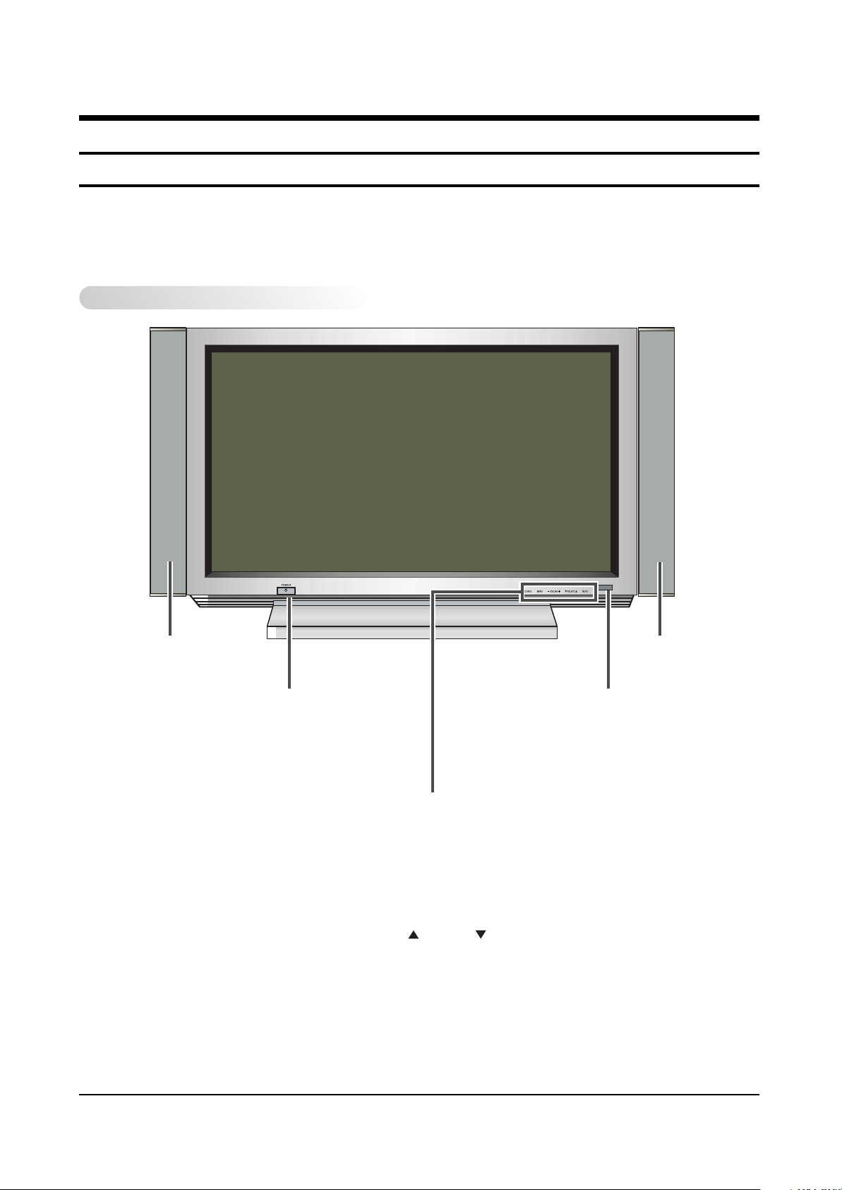
9-1-1(A) PDP(Plasma Disply Panel)
Front Panel
SPEAKER SPEAKER
POWER
Press to turn the
PDP on and off.
SOURCE
External input selection.
MENU
Menu display.
-
VOLUME +
Volume adjustment.
SELECT
Control the cursor in the Menu.
MUTE
Temporary sound switch-off.
Remote Control Signal Receiver
Aim the remote control towards this spot on
the PDP.
Page 2
Handling Description
9-2 Samsung Electronics
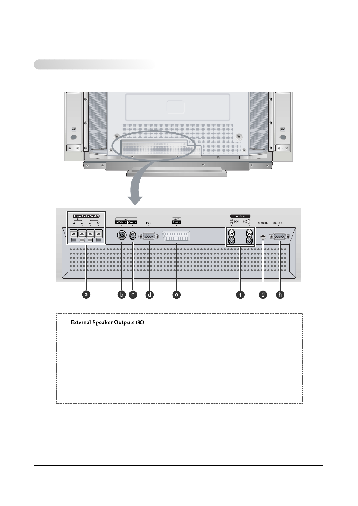
Real Panel
a) )
Connect external speakers.
e) SCART Audio/Video Input
Connect a audio/video signal from external
sources like VCRs.
b) S-VIDEO Input
Connect a S-Video signal from an S-VHS VCRs
or DVD players.
f) Audio Inputs (Video/PC)
Connect a audio signal from external sources
like VCRs or PC.
c) VIDEO Input
Connect a video signal from external sources
like VCRs or DVD players.
d) PC Input
Connect a PC signal from an PC.
g) RS-232C Input
Connect the RS-232C output your PC.
h) RS-232C Onput
Connect the RS-232C iutput of another PDP.
Page 3

Handling Description
Samsung Electronics 9-3
9-1-1(B) REMOTE CONTROL
Flip the cover open in the arrow direction.
Page 4

Handling Description
9-4 Samsung Electronics
9-2 Wall Mount
9-2-1 Notice for installing
1. Do not install the PDP on any place other than veritical walls.
2. To protect the performance of the PDP and prevent problems, avoid the following place :
● Next to spring coloer detectors.
● Places subject to vibration or shock.
● Near high voltage cables.
● Around heating apparatus.
3. Install the PDP considering the construction of the wall.
4. Use only recommended parts and components for installation.
9-2-2 Parts(wall attachment panel is sold separately.)
Fixing bolt Insulation rubber
Page 5
Handling Description
Samsung Electronics 9-5
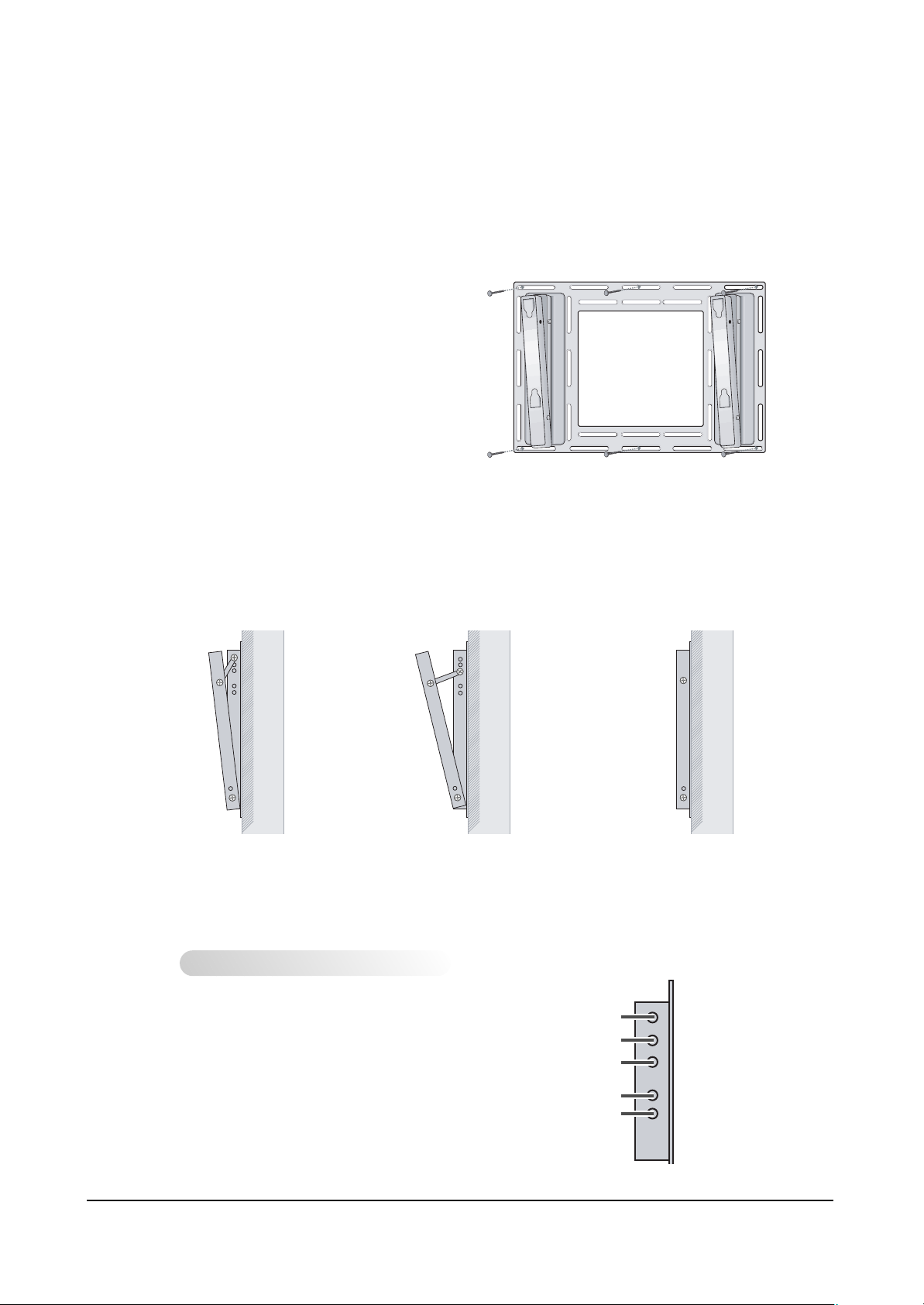
9-2-3 Installing the Display on the Wall Attachment Panel :
1. Check for the stability of the wall where the PDP is to be installed. If the wall is not enough strong to
support the PDP, strengthen the wall before installation.
2. Fix the wall attachment panel on the
wall using bolts as shown in the figure:
Fixing bolts must protrude from the
wall appox. 0.6 inches.
3. Using the wall attachment panel, you may adjust the angle of the display from 0 to 20 degrees. The
angle can be set in 5 stages with 5 degrees of distance each using the angle control holes on the sides
of the panel.
When the angle has
been set to 5 degrees.
When the angle has
been set to15 degrees.
When the panel hasn’t
been tilted.
Angle control holes
5 degrees of tilt
10 degrees of tilt
15 degrees of tilt
No tilt
20 degrees of tilt
Page 6

Handling Description
9-6 Samsung Electronics
4. Remove four large screws from the rear side of the display.
Insetr the hexagonal bolts, dish-type washers, and insulation
rubber into the place from which the four large screws
have been removed as shown in the following figure :
5. Put the insulation rubber point
protruding from the rear top of the
display in the groove on the top of the
wall attachment panel. Lift up the
display a little bit so that the
insulation rubber point at the bottom
of the rear side of the display is put to
the groove at the bottom of the wall
attachment panel. (Do not lift the
display with any pressure. The
insulation rubber at the top may be
taken off.)v
Bolt
Insulation rubber
Page 7

Handling Description
Samsung Electronics 9-7
9-2-4 Separating the Display from the Wall Attachment Panel :
Remove the fixing bolts from both sides(left and right) of the wall attachment panel. Lift and pull thebottom of the display a small amount, to separate the insulation rubber point from the bottom of the
wall attachment panel.
Lift the display and separate the insulation rubber point from the groove on top of the wall attachment
panel.
6. Insert the fixing bolts into the boltholes on both
sides(left and right) of the wall fixing panel.
Keep the fixing bolts tight to prevent the display
from separating from the panel, and falling to the
floor.
Page 8

9-8 Samsung Electronics
MEMO
 Loading...