

Page 1
Alignment and Adjustments
Samsung Electronics 4-1
4. Alignment and Adjustments
4-1 Service Mode
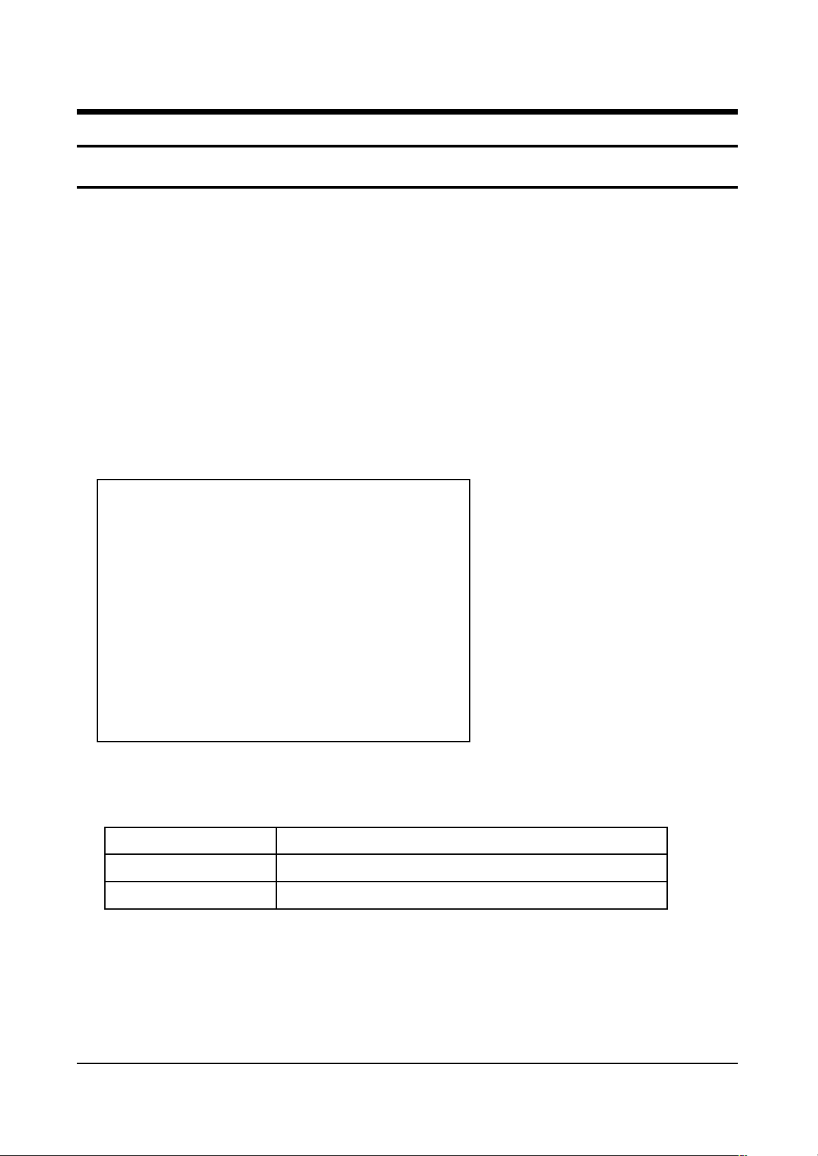
4-1-1 SERVICE MODE ENTRY METHOD (General Transmitter)
1. Turn off the power to make the SET STAND-BY mode.
2. In order to enter the Service Mode, select MUTE-1-8-2-POWER.
✳ In case entry into SERVICE MODE is unsuccessful, repeat the procedures above.
4-1-2 Initial DISPLAY State in times of SERVICE MODE Switch overs
4-1-2(A) OSD DISPLAY
4-1-2(B) BUTTONS OPERATIONS WITHIN SERVICE MODE
1. PW364A 9. CXA2101Q-2
2. VPC3230 10. PinP Control
3. SDA9400 11. OSD Position
4. SDA9280 12. Test Position
5. AD9884-Video 13. Option Table
6. AD9884-PC 14.Reset
7. AD9884-DTV
8. CXA2101Q-1
Release Time :
Menu
Joystick UP/DOWN
Joystick
Entire menu display
Cursor move to select items
Enable to increase and decrease the data of the selected items
Page 2
Alignment and Adjustments
4-2 Samsung Electronics
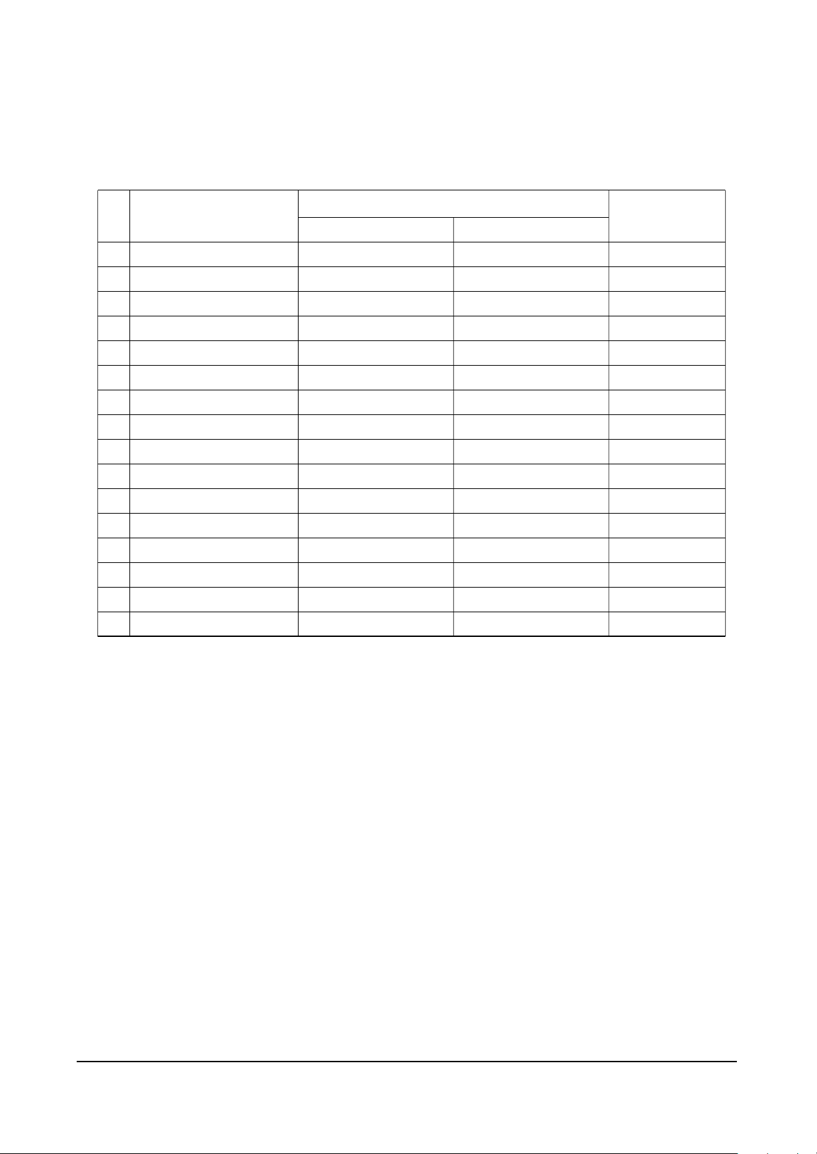
4-1-3 Details of Control
4-1-3(A) PW364A
NO
1
2
3
4
5
6
7
8
9
10
11
12
13
14
15
16
OSD
H Position
V Position
Red Gain
Green Gain
Blue Gain
Red offset
Green offset
Blue offset
APL on/off
High Light
Low Light
Shift Pixel
Test
Pixel Number
Shift Line
Time
PC
-
-
134
134
134
123
123
123
1
134
123
ON
0
4
4
4
NTSC
-
-
115
115
115
116
116
116
1
115
116
ON
0
4
4
4
PAL
-
-
115
115
115
116
116
116
1
115
116
ON
0
4
4
4
Video/S-VHS/Scart
Page 3
Alignment and Adjustments
Samsung Electronics 4-3
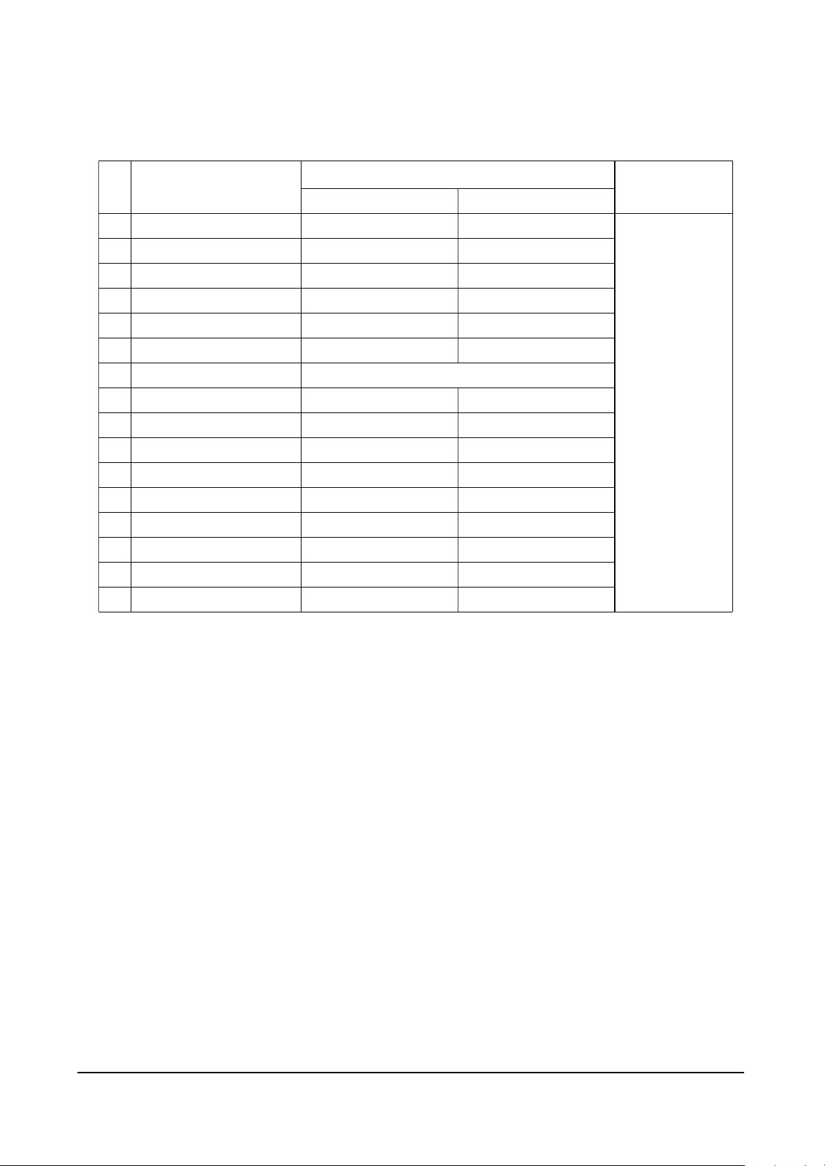
4-1-3(B) VPC3230
NO
1
2
3
4
5
6
7
8
9
10
11
12
13
14
15
16
OSD
CIP Bright
CIP Cont
IF Comp
Chroma Band
Ena Luma
HPLL Speed
Luma Delay
3230 Bright
3230 Contrast
H LPF Y/C
H LPF Chroma
H peaking
Coaring Off/On
CIP Sat Cb
CIP Sat Cr
CIP Tint
PC
Need not be
considered.
NTSC
-
-
0
3
1
1
168
36
1
0
2
1
-
-
-
PAL
-
-
0
3
1
1
168
36
1
0
2
1
-
-
-
Video/S-VHS/Scart
No. 9 is set separately.
Page 4
Alignment and Adjustments
4-4 Samsung Electronics
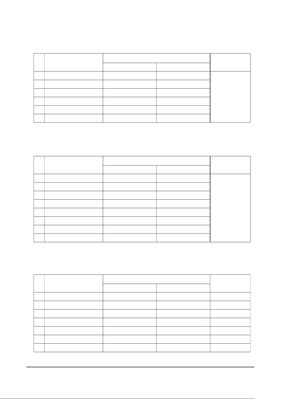
4-1-3(C) SDA9400
4-1-3(E) AD9884
NO
1
2
3
4
5
6
OSD
SNR On
VCSNR On
HCSNR On
DTNR On
TNRCLY
TNRCNC
PC
Need not be
considered.
NTSC
1
1
0
1
5
5
PAL
1
1
0
1
5
5
Video/S-VHS/Scart
4-1-3(D) SDA9280
NO
1
2
3
4
5
6
7
8
OSD
CTI Thresh
CTI Trawid
Y-Delay
LPF Gain
BPF Gain
HPF Gain
Phacom
Cor
PC
Need not be
considered.
NTSC
0
0
9
4
8
8
0
1
PAL
0
0
9
4
8
8
0
1
Video/S-VHS/Scart
NO
1
2
3
4
5
6
7
OSD
Red Gain
Green Gain
Blue Gain
137Red Offset
Green Offset
Blue Offset
Current
PC
127
128
132
31
30
29
-
NTSC
145
128
128
34
30
38
1
PAL
145
128
128
34
30
38
1
Video/S-VHS/Scart
Page 5

Alignment and Adjustments
Samsung Electronics 4-5
✥ Video, S-VHS Color Tone Offset
(AD9884Adjusting AD9884. It is the result of the data computation against the standards.
NO
1
2
3
4
5
6
OSD
Red Gain
Green Gain
Blue Gain
137Red Offset
Green Offset
Blue Offset
Offset
-2
-
-29
-1
-
+1
Data
122
128
94
34
28
38
Offset
-2
-
-21
-1
-
+1
Data
122
128
102
34
28
38
Offset
-
-
-
-
-
-
Data
124
128
123
35
28
37
Offset
-25
-
+6
+3
-
+1
Data
99
128
129
38
28
38
Offset
-37
-
+28
+4
-
-1
Data
87
128
151
39
28
37
Cool2
267,278
Cool1
273,285
Normal(Standard)
282,296
Warm2
293,309
Warm2
312,329
4-1-3(F) CXA2101-1
NO
1
2
3
4
5
6
7
8
9
10
11
12
13
14
15
16
17
OSD
Sub Bright
Limit Level
System
D-Color
R Drive
G Drive
B Drive
R CutOff
G CutOff
B CutOff
ABL Mode
ABL TH
H Sep Sel.
Fix Sync.
V Time Con
H Width
HHD timi Con
PC
Need not be
considered.
NTSC
51
0
1
1
10
4
4
32
32
32
0
0
0
0
1
1
0
PAL
51
0
1
1
4
4
4
32
32
32
0
0
0
0
1
1
0
Video/S-VHS/Scart
Page 6

Alignment and Adjustments
4-6 Samsung Electronics
4-1-3(G) CXA2101-2
NO
1
2
3
4
5
6
7
8
9
10
11
12
13
14
15
16
17
18
OSD
HS Mask
Sub Cont
Sub Color
Sub Hue
Sub SHP
R-Y/R (Not stored.)
R-Y/B (Not stored.)
G-Y/R (Not stored.)
G-Y/B (Not stored.)
PABL Level
SHP FO
Pre/over
CTI Level
LTI Level
DC-Tran
D-Pic
Cr-Offset1
Cb-offset1
PC
Need not be
considered.
NTSC
1
15
10
8
3
7
15
11
4
8
2
3
1
0
1
1
0
15
PAL
1
15
10
8
3
9
15
12
4
8
2
3
1
0
1
1
7
7
Video/S-VHS/Scart
4-1-3(H) Y/C DELAY[9280: ADJUSTING C3230 AFTER FIXING 9. )
VIDEO
7
NTSC
VIDEO
6
SECAM
VIDEO
6
S-VHS
6
S-VHS
7
S-VHS
7
PAL
Page 7

Alignment and Adjustments
Samsung Electronics 4-7
1 Setting data for P-modes.
1. VIDEO, S-VHS
˘ Factory-In/P-mode is high at the time of factory-out : Custom
˘ Factory Reset P-MODE : Dynamic
2. PC MODE W/B
˘ Factory-In/P-mode is high at the time of factory-out : Custom
˘ Factory Reset P-MODE : Dynamic
❏ When the factory mode custom contrast is bright, turn on the S/W Limit (PC interoperability) using the White Saturation
(PW364A).
3. White Balance Coordinates
[Signaling conditions]
! Video, S-VHS, Scart : 10-Step By VP-8400A
@ PC : 16 Gray(0,1,2,#,4,5,6,7,8,(,10....15)-tp36b(Soft for PC review )
NT
90
50
50
40
50
P-MODE
Color-Tone
Contrast
Bright
Sharpness
Color
Tint
Custom
Normal
PAL
90
50
50
50
-
NT
90
50
50
40
50
Standard
Normal
PAL
-
-
-
50
-
NT
90
50
60
40
50
Sports
Cool-1
PAL
90
50
60
50
-
NT
80
55
50
40
50
Movie
Warm-1
PAL
80
55
50
50
-
NT
6
60
40
40
50
Mild
Warm-1
PAL
60
60
40
50
-
NT
100
45
75
40
50
Dynamic
Cool-1
PAL
100
45
75
50
-
P-MODE
Contrast
Bright
Sharpness
Custom
100
90
2
High
100
50
4
Middle
75
60
3
Low
50
65
2
VIDEO
(TSB Pattern)
PC
(16 Gray)
T(K)
9300
9300
9300
9300
Y(fL)
21
0.9
13.5
0.95
y
296
296
296
296
x
282
282
282
282
High
Low
High(column()
Low(column#)
Evaluating
video quality
Evaluating
video quality
W/B
Page 8

Alignment and Adjustments
4-8 Samsung Electronics
4-1-4 White Balance Adjust Method
1. Press MUTE-1-8-2-POWER to enter the factory mode.
2. Enter AD9884
3. Adjust LOW coordinates as R, B OFFSET and HIGH coordinates as R, B GAIN.(GREEN is fixed.)
4. In AD9884, adjust brightness with V CONTRAST / V BRIGHT for VIDEO / DTV, and adjust with
GAIN DRIVE / OFFSET DRIVE for PC.
✥ W/B Adjustment SPEC(Suwon Factory Toshiba PATTERN)
➣ VIDEO MODE
➣ PC MODE
Adjustment
Coordinates
H-LIGHT
L-LIGHT
Coordinates
Value
x : 282
y : 296
Y : 21[f\]
x : 282
y : 296
Y : 0.9[f\]
Adjustment
Deviation
±: 3
±: 3
±: 3
±: 5
±: 5
± : 0.1
Adjustment
Coordinates
H-LIGHT
L-LIGHT
Coordinates
Value
x : 282
y : 296
Y : 13.5[f\]
x : 282
y : 296
Y : 0.95[f\]
Adjustment
Deviation
±: 3
±: 3
±: 3
±: 5
±: 5
± : 0.1
Page 9

Alignment and Adjustments
Samsung Electronics 4-9
PS50P2HT
70.086
85.080
85.080
70.087
85.039
59.940
72.809
75.000
85.008
60.000
72.000
75.000
85.000
56.250
60.317
72.188
75.000
85.061
60.004
70.069
75.029
84.997
75.000
60.000
75.000
60.020
75.025
60.000
Dot x Line
640 x 350
640 x 400
720 x 400
640 x 480
848 x 480
800 x 600
1024 x 768
1152 x 864
1280 x 768
1280 x 1024
1366 x 768
Standard
VGA
W-VGA
SVGA
XGA
W-XGA
SXGA
WXGA+
Vertical
FREQUENCY(Hz)
31.469
37.861
37.861
31.469
37.927
31.469
37.861
37.500
43.269
29.838
35.156
36.072
37.650
42.925
37.879
48.077
46.875
53.674
48.363
56.476
60.023
68.677
67.500
47.700
60.150
63.981
79.976
48.200
Horizantal
FREQUENCY(Hz)
N
N
P
P
P
N
N
N
N
P
P
P
P
N/P
P
P
P
P
N
N
P
P
P
P
P
P
P
N
Vertical
POLARITY
P
P
N
N
N
N
N
N
N
N
N
N
N
N/P
P
P
P
P
N
N
P
P
P
N
N
P
P
N
Horizantal
POLARITY
N : Negative / P : POSITIVE
Page 10

Alignment and Adjustments
4-10 Samsung Electronics
4-2 Adjusting the Discharge Voltage Of the Main Unit While Replacing ASS'Y (Body Part)
■ Turning the variable resistor clockwise reduces voltage except VG, V9, and VR(6).
OUTPUT
VE
VSET
VS
VSCAN
VA
VSAMP
VG
V9
V5D
VR(6)
VSB
Voltage(V)
See the labels
attached on the
base chassis
12
18.3
9
5.3
5
5.2
❈ When you replace the SMPS unit you should adjust the VR(6V) to +5V.
Page 11

Alignment and Adjustments
Samsung Electronics 4-11
4-3 Fault Finding Using MULTI METER
Parts defects can be found for DIODE TRANSISTOR IC, using MULTI TEST including
Forward/Reverse direction Multi Test. Of course, in case resistance of several ohms and COIL are connected in parallel circuit, the lock out circuit parallel connected to part must be severed.
1.DIODE
2. TRANSISTOR
● For NPN(KSC815-Y, 2SC2068, 2SC2331-Y)
● For PNP(KSA539-Y)
Forward Direction
Hundreds of ohms
Reverse Direction
Infinity
Between Anode and Cathode
C (COLLECTOR)
E
B(BASE)
BC
C (COLLECTOR)
E
B(BASE)
BC
E (EMITTER)
E (EMITTER)
Forward Direction
Hundreds of ohms
Hundreds of ohms
Infinity
Reverse Direction
Infinity
Infinity
Infinity
Between B and E
Between B and C
Between E and C
Forward Direction
Hundreds of ohms
Hundreds of ohms
Infinity
Reverse Direction
Infinity
Infinity
Infinity
Between B and E
Between B and C
Between E and C
+- +-
Page 12

Alignment and Adjustments
4-12 Samsung Electronics
3. IC (INTEGRATED CIRCUIT)
IC has built in DIODE against overvoltage in PIN. Generally, except for internal circuit defects, IC defects
can be found, by measuring the DIODE.
✴ Defects have SHORT(0 ohm) for both forward and reverse direction.
Hundreds of ohms
Forward Direction
Reverse Direction
Varying depending on IC but generally normal
Infinity in DIODE TEST MODE
 Loading...