

Page 1
1
Your New Plasma Display Panel
ENG
➢
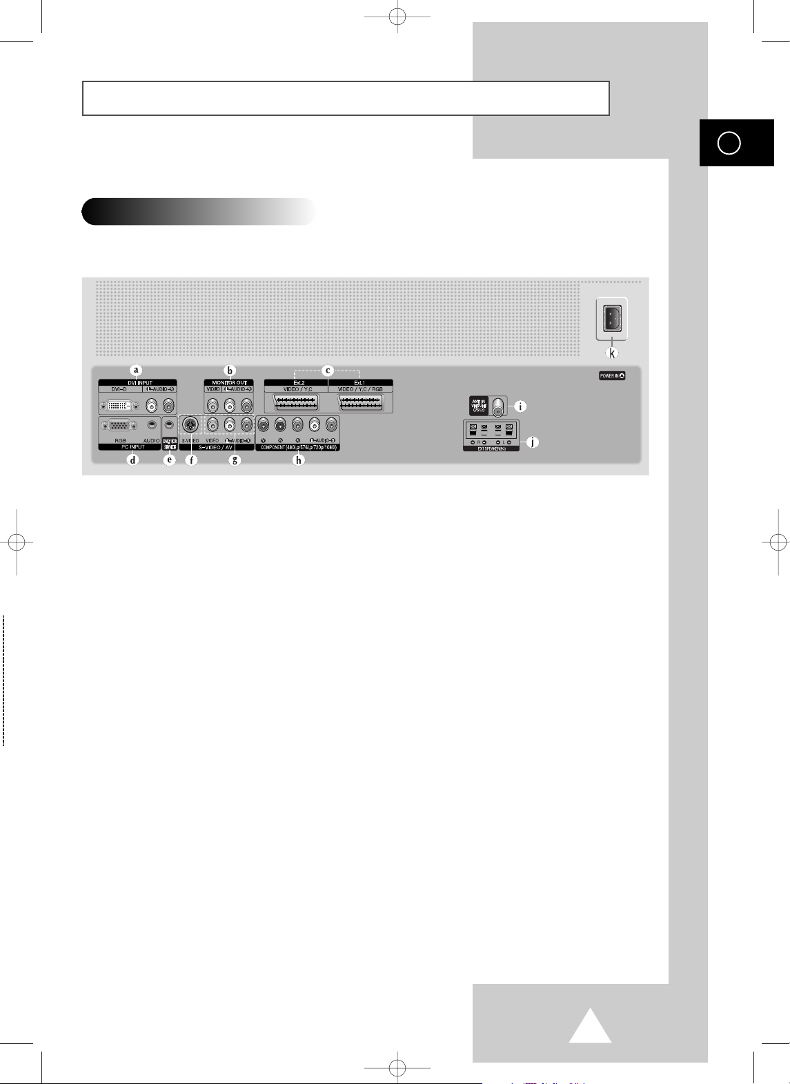
The actual configuration on your PDP may be different,
depending on your model.
Rear Panel
a) DVI INPUT
Connect to digital video output jack for device
with DVI output.
b) MONITOR OUT (VIDEO / L-AUDIO-R)
Outputs for external devices
c) Ext.1, Ext.2
Inputs or outputs for external devices, such as
VCR, DVD, video game device or video disc
players.
d) PC INPUT (RGB IN / AUDIO)
Connect to the video and audio output jack on
your PC.
e) ONLY FOR SERVICE
Connector for service only.
f) S-VIDEO
Video and audio inputs for external devices with
an S-Video output, such as a camcorder or VCR.
g) AV (VIDEO / L-AUDIO-R )
Video and audio inputs for external devices, such
as a camcorder or VCR.
h) COMPONENT
Video (Y/Pb/Pr) and audio (L-AUDIO-R) inputs for
Component.
i) ANT IN VHF/UHF (75Ω)
75Ω Coaxial connector for Aerial/Cable Network.
j) EXT SPEAKER(8Ω)
Connectors for external speakers.
K) POWER IN
Connect the supplied power cord.
BN68-00699A-00_Eng 4/13/04 11:17 AM Page 7
Page 2
2
ENG
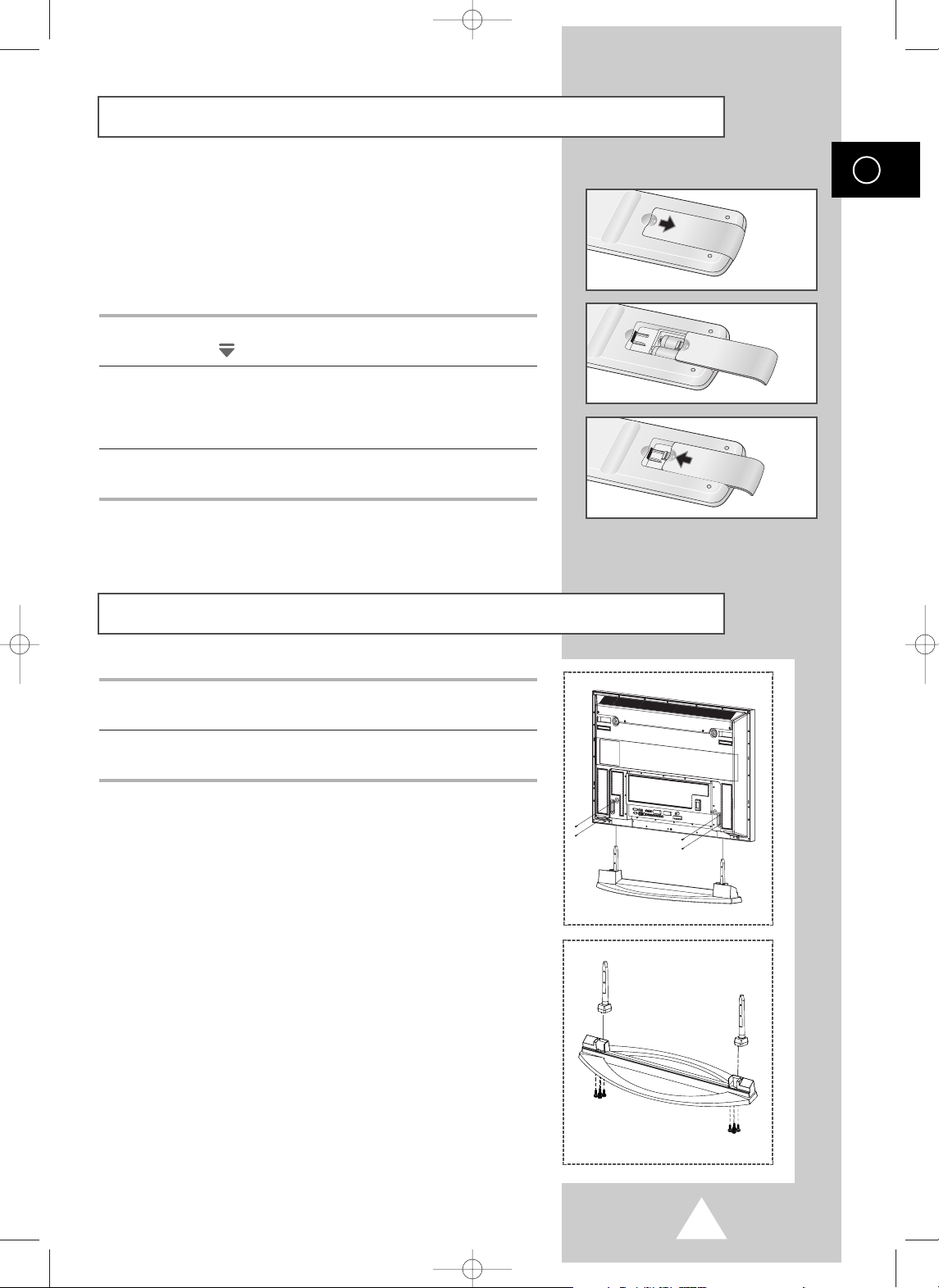
You must insert or replace the batteries in the remote control when
you:
◆ Purchase the PDP
◆ Find that the remote control is no longer operating
correctly
1 Remove the cover on the rear of the remote control by pressing
the symbol ( ) downwards and then pulling firmly to remove it.
2 Insert two R03, UM4, “AAA” 1.5V or equivalent batteries taking
care to respect the polarities:
◆-on the battery against -on the remote control
◆+on the battery against +on the remote control
3 Replace the cover by aligning it with the base of the remote
control and pressing it back into place.
Inserting the Batteries in the Remote Control
Assembling the Stand-Base
1 Assemble two support pins with the stand base and firmly secure
both sides of the support pins using 8 screws provided.
2 Assemble the PDP with the stand and firmly secure the PDP using
4 screws provided.
➢
◆
Two or more people should carry the PDP. Never lay the
PDP on the floor because of possible damage to the screen.
Always store the PDP upright.
BN68-00699A-00_Eng 4/13/04 11:17 AM Page 9
Page 3
3
ENG
Installing the Display on the Wall Attachment Panel
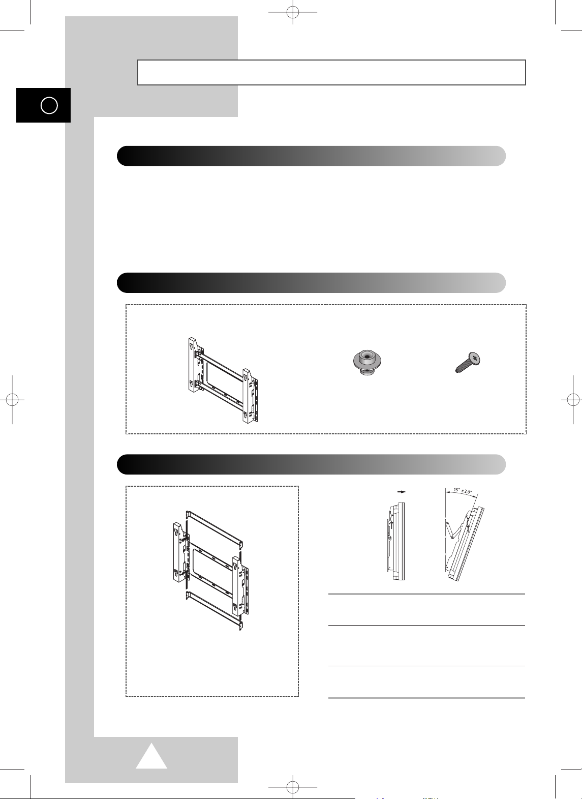
Wall Mount Bracket
Mounting Kits
4 EA 4 EA
Plastic Hanger Screws
How to Adjust Mounting Angle
1 Secure the PDP to the wall mount bracket.
(Please refer to the following instructions.)
2 Set the angle by pulling the upper end of the
PDP attached to bracket in the direction of the
arrow.
3 The angle can be adjusted from 0° to 15° by
±2°.
The wall mount bracket is delivered
separately. Please tighten the captive
screw in the direction of the arrow after
assembling the bracket.
Installation Notes
◆
Do not install the PDP on any place other than vertical walls.
◆
To protect the performance of the PDP and prevent troubles, avoid the followings:
-
Do not install next to smoke and fire detectors.
-
Do not install in an area subjected to vibration or high voltage.
-
Do not install near or around any heating apparatus.
◆
Use only recommended parts and components.
(depending on your model)
BN68-00699A-00_Eng 4/13/04 11:17 AM Page 10
Page 4
4
ENG
Installing the Display on the Wall Attachment Panel (continued)
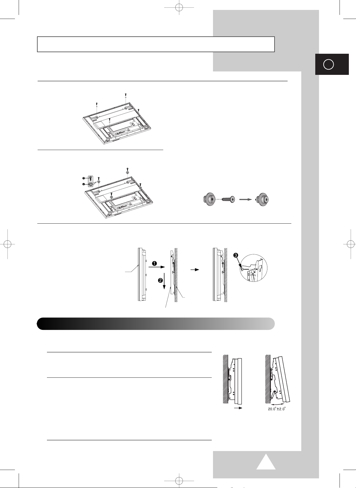
1 Remove the screws from the back of the PDP.
3 Tighten the screws of the plastic hanger to the
back side of the PDP.
4 Put the 4 pegs on the PDP in the grooves of the wall mount bracket and pull down on the PDP (!) to
secure it to the wall mount bracket (
@). Tighten the screws as shown (#) so that the PDP cannot be
separated from wall mount bracket.
2 Use the screws and assemble the plastic
hanger.
☛
◆ Please ask the installers to install the
wall mount bracket.
◆ Please be sure to check if the plastic
hanger is completely secured on both
the left and right side after hanging
the PDP on the wall mount bracket.
◆ Please avoid catching your fingers
while installing and adjusting the
angle.
◆ Please tightly secure the wall mount
bracket to the wall to avoid injury
from a falling PDP.
Connecting External Devices to the PDP
1 Be sure to remove the safety pins underneath the PDP.
◆ If the safety pins are not removed, the angle cannot be adjusted.
Any attempt to do so may cause damage to the PDP.
2 Pull out the bottom of the PDP (which has been attached to the Wall
Mount Bracket) in the direction indicated by the arrows (refer to
the illustration) until it clicks.
◆ Using the PDP After Connecting External Devices.
Be sure to secure the PDP by inserting the 2 safety pins after
readjusting the angle of the PDP to 0
o
.
◆ For safety, be sure to secure the PDP using the safety pins.
If the safety pins are not used, the PDP may fall, causing serious
injury.
➢
The exterior of the PDP may be different than the picture.
(Assembly and installation of the plastic hanger is the same.)
◆
To connect external devices such as a DVD or a Home Theater System to the PDP, please refer
to following instructions:
PDP panel
Wall attachment panel bracket
Wall
BN68-00699A-00_Eng 4/13/04 11:18 AM Page 11
Page 5

5
Connecting Speakers
ENG
1 Remove the screws on the rear of the PDP.
2 Hang the two “T” shaped hangers
on the square holes on the rear of
the PDP.
3 Tighten the PDP and the speaker bracket using the screws removed from the PDP.
➢
When moving your PDP, do NOT hold the speaker connected to your PDP. It may damage the
bracket clamping the speaker and your PDP together and result in a drop of your PDP and a risk of
personal damage and injury.
BN68-00699A-00_Eng 4/13/04 11:18 AM Page 12
Page 6

6
Connecting Speakers (continued)
ENG
Connect the speaker audio cable to the external speaker output jack on the rear of the PDP matching
the “+” and “
-
” ends of the cable with the diagram on the PDP.
➢
◆ The speakers MUST have to a power handling capability of 10 watts minimum (impedance 8Ω).
◆ When you connect the speaker wire to the external speaker out connector, first bind the speaker wire
round the ferrite core to secure it.
➢
Before connecting the speaker wire to the PDP, turn off your PDP.
Ferrite Cores
The ferrite cores are used to attenuate undesired signals.
When connecting cables, attach one of these ferrite cores to
the cable near the connector.
BN68-00699A-00_Eng 4/13/04 11:18 AM Page 13
Page 7

7
ENG
In order to watch television programmes broadcast via a satellite
network, you must connect a satellite receiver to the rear of the
PDP. Also, in order to descramble a coded transmission signal, you
must connect a decoder to the rear of the PDP.
Using a Coaxial cable
Connect a coaxial cable to the:
◆ Receiver (or Decoder) output socket.
◆ Television aerial input socket.
➢
If you wish to connect both a satellite receiver (or decoder)
and a VCR, you should connect the:
◆ Receiver (or Decoder) to the VCR
◆ VCR to the PDP
Otherwise, connect the receiver (or decoder) directly to the
PDP.
Connecting a Satellite Receiver or Decoder
Rear of the PDP
Satellite receiver/
Decoder
To view television channels correctly, a signal must be received by
the set from one of the following sources:
◆ An outdoor aerial
◆ A cable television network
◆ A satellite network
1 In the first three cases, connect the aerial or network input cable to
the 75Ω coaxial socket on the rear of the PDP.
2 If you are using an indoor aerial, you may need to turn it when
tuning your PDP until you obtain a picture that is both sharp and
clear.
For further details, refer to:
◆ “Storing Channels Automatically” on page 19
◆ “Storing Channels Manually” on page 20
➢
When installing or re-installing your PDP, be sure to use the
supplied coaxial antenna cable. If you connect using a different
coaxial cable, there is risk of noise or interference to the screen
image. (You must not use another general purpose cable.)
Connecting to an Aerial or Cable Television Network
Rear of the PDP
Cable Television
Network
or
BN68-00699A-00_Eng 4/13/04 11:18 AM Page 14
Page 8

8
ENG
Connecting to the External Devices
“MONITOR OUT” are used for the equipment with an RGB output, such as
video game devices or video disc players.
Rear of the TV
(Input/Output)
①
This end can be fitted with:
◆ A SCART connector
◆ Three RCA connectors (VIDEO + AUDIO-L/R)
or
①
VCR
Decoder /
Video game device
Video disc player
Satellite receiver
DVD
②
③
Rear of the TV
(Input/Output)
Camcorder
Video disc player
Video game device
Input/Output Specification
Connector
Input Output
Video Audio (L/R) S-Video RGB Video + Audio (L/R)
Ext.1 ✔✔ ✔✔ Only TV output is available.
Ext.2 ✔✔ ✔ Output you can choose.
BN68-00699A-00_Eng 4/13/04 11:19 AM Page 52
Page 9

9
ENG
Connecting to the S-Video Input
The S-VIDEO and RCA (AUDIO-L/R) connectors are used for equipment with an S-Video output,
such as a camcorder or VCR.
Rear of the TV
Camcorder
VCR
①
To play picture and sound, both the S-VIDEO and RCA connectors must be used.
and
①
☛
Whenever you connect an audio or video system to your television,
ensure that all elements are switched off. Refer to the documentation
supplied with your equipment for detailed connection instructions
and associated safety precautions.
BN68-00699A-00_Eng 4/13/04 11:19 AM Page 53
Page 10

10
ENG
Connecting to the DVI Input
Connecting to the PC Input
The “RGB” (video) and “AUDIO” connectors are used for interfacing with your PC.
Personal Computer
and
Rear of the TV
The “DVI” (video) and “L-AUDIO-R” connectors are used for equipment with a DVI output.
Personal Computer
Rear of the TV
and
BN68-00699A-00_Eng 4/13/04 11:19 AM Page 54
Page 11

11
ENG
Connecting to the Component Input
①
The “COMPONENT” connectors are
used for DTV receiver or DVD.
(480i,p/576i,p/720p/1080i)
DVD
Rear of the TV
DTV receiver
or
BN68-00699A-00_Eng 4/13/04 11:19 AM Page 55
Page 12

12
ENG
Connecting and Using the Home Theater System
Connecting the Home Theater System
①
Connect the monitoring audio out L, and
R jacks of the MONITOR OUT on the
rear-side connection panel of the PDP
TV to the AUDIO IN jacks of the DVD
Home Theater System (or AV Receiver)
using the audio cable.
②
Press the TV/VIDEO button to select the
desired external device connected to the
PDP TV.
③
If you want to hear the sound through
separate speakers, cancel the internal
amplifier.
To Display the DVD Home Theater
!
Turn the PDP on and press the TV/VIDEO button to select the Ext.1 (or Ext.2).
@
Be sure to connect the video cable properly if desired external input (Ext.1 or Ext.2) cannot be
selected.
#
Play the DVD after activating the DVD Home Theater System.
$
Use the volume control of the Home Theater System while watching the PDP using the DVD
Home Theater, where the PDP TV does not produce the audio.
DVD Home Theater
Rear of the TV
AV Receiver Amplifier
①
②
Use the Monitor Out ports of the PDP for Home Theater System Connections.
☛
◆ Refer to corresponding user’s manual from the manufacturer for wiring the
speakers to the DVD Home Theater System (or AV Receiver).
◆ Disable the PDP TV internal speaker to enjoy the rich sound through the
speakers of your Home Theater System.
◆ In this case, enjoy the sound from the Home Theater System while the PDP TV
does not produce the audio.
BN68-00699A-00_Eng 4/13/04 11:19 AM Page 56
 Loading...