

Page 1
PDP-MONITOR
(PLASMA DISPLAY PANEL)
PS42D4ST
Owner’s Instructions
Before operating the unit,
please read this manual thoroughly,
and retain it for future reference.
Intended for Commercial Use and Operation
ON-SCREEN MENUS
PICTURE IN PICTURE (PIP)
MDC
(MULTIPLE DISPLAY CONTROL)
Page 2
ENG
Warning! Important Safety Instructions
The lightning flash and arrow
CAUTION
RISK OF ELECTRIC SHOCK
DO NOT OPEN
head within the triangle is a
warning sign alerting you of
“dangerous voltage” inside
the product.
CAUTION:TO PREVENT ELECTRICAL SHOCK, DO NOT
REMOVE REAR COVER, NO USER SERVICEABLE PARTS
INSIDE. REFER SERVICING TO QUALIFIED SERVICE
PERSONNEL.
Note to CATV system installer: This reminder is provided to call CATV system installer's attention to Article 82040 of the National Electrical Code (Section 54 of Canadian Electrical Code, Part I), that provides guidelines for
proper grounding and, in particular, specifies that the cable ground shall be connected to the grounding system of
the building as close to the point of cable entry as practical.
Caution: FCC/CSA regulations state that any unauthorized changes or modifications to this equipment may void
the user's authority to operate it.
Caution: To prevent electric shock, match the wide blade of plug to the wide slot, and fully insert the plug.
Attention: pour eviter les chocs electriques, introduire la lame le plus large de la fiche dans la borne
correspondante de la prise et pousser jusqu'au fond.
Important: One Federal Court has held that unauthorized recording of copyrighted TV programs is an
infringement of U.S. copyright laws.Certain Canadian programs may also be copyrighted and any unauthorized
recording in whole or in part may be in violation of these rights.
TO PREVENT DAMAGE WHICH MAY RESULT IN FIRE OR ELECTRIC SHOCK HAZARD, DO NOT
EXPOSE THIS APPLIANCE TO RAIN OR MOISTURE.
The exclamation point within
the triangle is a warning sign
alerting you of important
instructions accompanying
the product.
2
Page 3

Important Warranty Information Regarding PDP Format Viewing
Wide screen format PDP Displays (16:9,the aspect ratio of the screen width to height) are primarily
designed to view wide screen format full-motion video. The images displayed on them should primarily
be in the wide screen 16:9 ratio format, or expanded to fill the screen if your model offers this feature and
constantly moving. Displaying stationary graphics and images on screen, such as the dark side-bars on
non-expanded standard format PDP video and programming, should be limited to no more than 5% of
the total PDP viewing per week.
Additionally, viewing other stationary images and text such as stock market reports, video game displays,
station logos, web sites or computer graphics and patterns, should be limited as described above for all
PDP displays.
PDP Displays that leave subtle, but permanent burned-in ghost images in the PDP picture. To avoid
this, vary the programming and images, and primarily display full screen moving images, not stationary
patterns or dark bars.
different formats as a full screen picture.
Be careful in the selection and duration of PDP formats used for viewing. Uneven PDP aging as a result
of format selection and use, as well as burned-in images, are not covered by your Samsung limited
warranty.
Displaying stationary images that exceed the above guidelines can cause uneven aging of
On PDP models that offer picture sizing features, use these controls to view
ENG
3
Page 4

ENG
User Instructions
◆ Screen Image retention
Do not display a still image (such as on a video game or when hooking up a PC to this PDP) on the
plasma display panel for more than 2 hours as it can cause screen image retention. This image
retention is also known as “screen burn”. To avoid such image retention, reduce the degree of
brightness and contrast of this screen when displaying a still image.
◆ Cell Defect
The plasma display panel consists of fine cells. Although the panels are produced with more than
99.9 percent active cells, there may be some cells that do not produce light or remain lit.
◆ Height
The PDP can normally operate only under 2000m in height. It might abnormally function at a place
over 2000m in height and do not install and operate there.
◆ Warranty
- Warranty does not cover any damage caused by image retention.
- Burn-in is not covered by the warranty.
4
Page 5
User Instructions
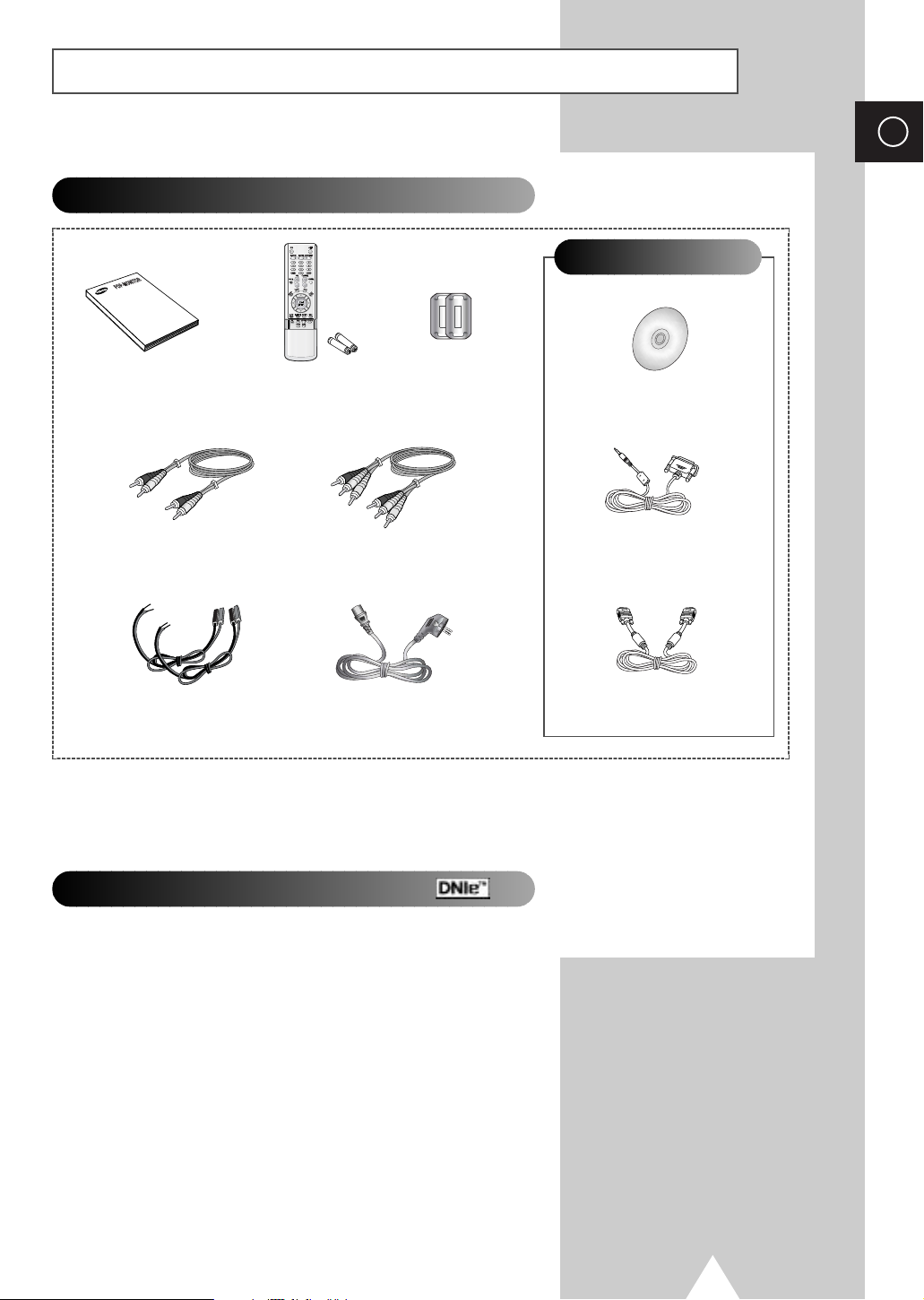
Checking Parts
ENG
A Separated Sales
Owner’s Instructions Remote Control/
A/V Cable
(1EA)
Speaker Wires
(2EA)
The PS42D4ST model uses the same MDC program CD used for PS42P3ST model.
➢
AAA Batteries
Ferrite Cores for
Speaker Wire
A/V Cable
(1EA)
Power Cord
(2EA)
- MDC Software (RS232C)
MDC Cable
DNIeTM(Digital Natural Image engine)
Install CD
(RS232C)
PC Cable
This feature bring you more detailed image with 3D noise reduction, detail enhancement, contrast
enhancement and white enhancement. New image compensation Algorithm gives brighter, clearer,
much detailed image to you. DNIe
TM
technology will fit every signals into your eyes.
5
Page 6

ENG
Contents
◆ FOREWORD
■ Warning! Important Safety Instructions ......................................................... 2
■ Important Warranty Information Regarding PDP Format Viewing................. 3
■ User Instructions............................................................................................ 4
◆ CONNECTING AND PREPARING YOUR DISPLAY
■ Your New Plasma Display Panel................................................................... 8
■ Becoming Familiar with the Remote Control................................................. 10
■ Inserting the Batteries in the Remote Control................................................ 11
■ Assembling the Stand-Base.......................................................................... 11
■ Installing the Display on the Wall Attachment Panel..................................... 12
■ Connecting Speakers.................................................................................... 14
■ Switching On and Off..................................................................................... 16
■ Choosing Your Language.............................................................................. 16
◆ USING YOUR DISPLAY
■ Selecting the Color System (Video or S-Video Mode)................................... 17
■ Changing the Picture Mode........................................................................... 17
■ Adjusting the Picture Settings........................................................................ 18
■ Adjusting the Picture Settings (PC or DVI Mode).......................................... 19
■ Selecting the Picture Size.............................................................................. 20
■ Activating/Deactivating the Digital Noise Reduction Feature ........................ 20
■ Freezing the Current Picture ......................................................................... 21
■ Changing the Sound Mode............................................................................ 21
■ Adjusting the Sound Settings ........................................................................ 22
■ Extra Sound Settings..................................................................................... 23
-
Auto Volume
-
Melody
-
Pseudo Stereo / Virtual Surround
■ Adjusting the Image Preferences (PC Mode)................................................ 24
6
Page 7
Contents(continued)
◆ USING YOUR DISPLAY (CONTINUED)
■ Locking the Control buttons........................................................................... 25
■ Setting the MDC (Multiple Display Control)................................................... 25
■ Protecting the Screen Burning....................................................................... 26
■ Displaying the PC Information....................................................................... 27
■ Displaying the Setting Information................................................................. 27
■ Setting and Displaying the Current Time....................................................... 28
■ Switching On and Off Automatically.............................................................. 29
■ Setting the Film Mode.................................................................................... 30
■ Viewing the Picture In Picture (PIP) .............................................................. 31
■ Listening to the Sound of the Sub Picture..................................................... 33
■ Viewing Pictures From External Sources...................................................... 33
◆ ADDITIONAL INFORMATION AND CONNECTIONS
■ Connecting to the Audio/Video Input............................................................. 34
■ Connecting to the S-Video Input.................................................................... 35
■ Connecting to the DVD/DTV RECEIVER Input............................................. 35
■ Connecting to the DVI Input .......................................................................... 36
■ Connecting to the RGB(PC) Input................................................................. 36
■ Setting up Your PC Software (Windows only)............................................... 37
■ Pin Configurations......................................................................................... 38
■ Input Mode (PC/DVI)..................................................................................... 39
■ Power Saver (PC mode only)........................................................................ 40
ENG
◆ RECOMMENDATIONS FOR USE
■ Troubleshooting: Before Contacting Service Personnel................................ 41
■ Care and Maintenance.................................................................................. 41
Symbols
Press Important Note
☛
➢
7
Page 8
ENG
Your New Plasma Display Panel
The actual configuration on your PDP may be different,
➢
depending on your model.
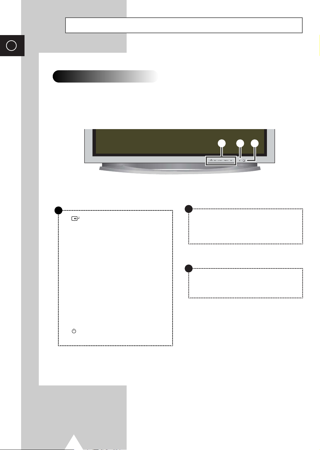
Front Panel
a
SOURCE
- External input selection.
- Store your settings in the menu.
- When the Main menu is displayed on screen,
the Main menu is not operated with source key.
MENU
Menu display and exit.
-
VOL +
- Volume adjustment.
- Adjust an option value respectively.
(VOL + : Enter to the selected menu.)
▼ SELECT ▲
Control the cursor in the menu.
a
c
b
b
Power Indicator
- Power Off; Red
- Power On; Off
- Timer On; Green
c
Remote Control Signal Receiver
Aim the remote control towards this spot on the
PDP.
I /
Press to turn the PDP on and off.
8
Page 9
Your New Plasma Display Panel
b
a
d
c
g
f
h
e
i
The actual configuration on your PDP may be different,
➢
depending on your model.
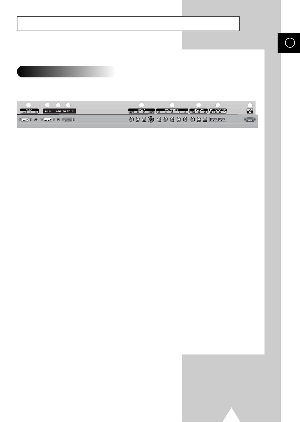
Rear Panel
For further details about connection, refer to pages 34~36.
➢
ENG
a) RS232C
-
IN : Used for the MDC function when connecting
PC or RS232C output of another PDP.
-
OUT :Used for the MDC function when
connecting with RS232C input of another
PDP.
b) DVI IN
Connect to the video output jack for device with
DVI output.
c) AUDIO
Connect to the audio output jack on your PC or any
device with DVI output. (It is audio input for b, d,
and e.)
d) RGB(PC) IN
Connect to the video output jack on your PC.
e) VIDEO IN
Video and audio inputs for external devices, such as
VCR, DVD, video game device or video disc players
(or for external devices with an S-Video output;
S-VIDEO).
f) COMPONENT IN
Video (Y/Pb/Pr) and audio (L/R) inputs for
component.
g) VIDEO OUT (VIDEO / L-AUDIO-R)
Used to output screen of Video or S-Video in PDP
when connecting video and/or audio input of
external devices.
h) EXT SPEAKER (8Ω)
Connect external speakers.
i) POWER IN
Connect the supplied power cord.
9
Page 10
ENG
Becoming Familiar with the Remote Control
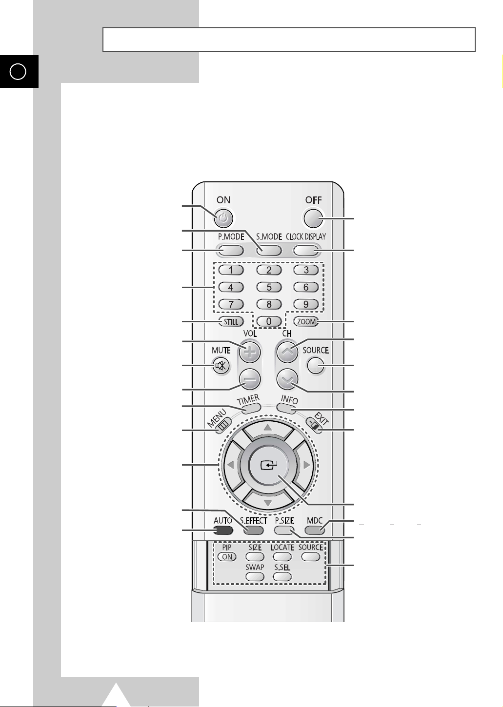
The remote control is used mainly to:
◆ Change sources and adjust the volume
◆ Set up the PDP using the on-screen menu system
PDP ON
PDP OFF
SOUND MODE SELECTION
PICTURE MODE SELECTION
NUMERIC BUTTONS
PICTURE STILL
VOLUME INCREASE
TEMPORARY SOUND SWITCH-OFF
Press it again , or -/+ button
➣
to turn the sound back on.
VOLUME DECREASE
SETTING THE TIMER
DISPLAY AND CLOSE THE MENU/
RETURN TO THE PREVIOUS MENU
MOVE TO THE REQUIRED MENU
ADJUST AN OPTION VALUE
SCREEN EFFECT SELECTION
(BURNING PROTECTION)
AUTO ADJUSTMENT IN PC MODE
OPTION/
RESPECTIVELY
CURRENT TIME DISPLAY
ZOOM/PANNING MENU DISPLAY
(ONLY PC MODE)
NEXT CHANNEL
(NOT AVAILABLE FOR THIS MONITOR)
EXTERNAL INPUT SELECTION
PREVIOUS CHANNEL
(NOT AVAILABLE FOR THIS MONITOR)
INFORMATION DISPLAY
EXIT FROM ANY DISPLAY
CHANGE CONFIRMATION
ULTIPLE DISPLAY CONTROL
M
PICTURE SIZE SELECTION
10
The performance of the remote control may be affected by bright light.
➢
PIP FUNCTIONS;
-PIP ON/OFF
- SIZE SELECTION (SIZE)
- LOCATION SELECTION (LOCATE)
- INPUT SOURCE SELECTION
(SOURCE)
- INTERCHANGE THE MAIN AND THE
SUB PICTURE (SWAP)
- SOUND SELECTION (S.SEL)
Page 11
Inserting the Batteries in the Remote Control
You must insert or replace the batteries in the remote control when
you:
◆ Purchase the PDP
◆ Find that the remote control is no longer operating
correctly
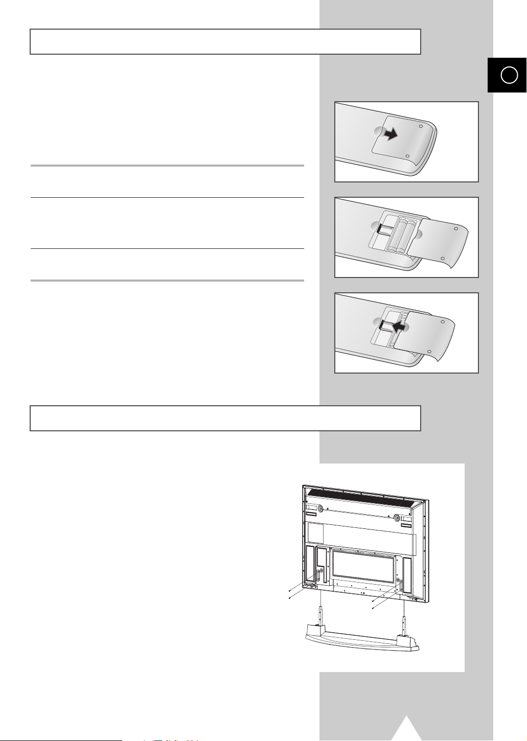
1 Remove the cover on the rear of the remote control by pressing
the symbol downwards and then pulling firmly to remove it.
2 Insert two R03, UM4, “AAA” 1.5V or equivalent batteries taking
care to respect the polarities:
◆-on the battery against -on the remote control
◆+on the battery against +on the remote control
3 Replace the cover by aligning it with the base of the remote
control and pressing it back into place.
ENG
Assembling the Stand-Base
Fit the Stand-Base into the guide hole on the bottom of
the monitor and tighten the left and right sides using
four screws for each side.
◆
➢
Two or more people should carry the PDP.
Never lay the PDP on the floor because of
possible damage to the screen. Always store the
PDP upright.
11
Page 12
ENG
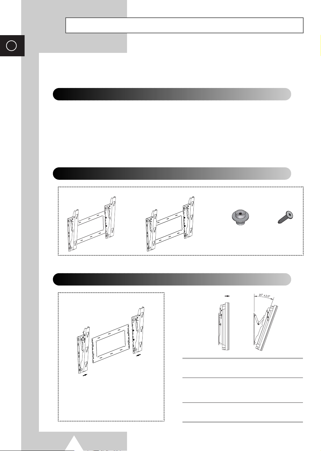
Installing the Display on the Wall Attachment Panel
This wall mount bracket installation guide is for the following models: WMN4230
☛
This installation guide may be different from the PDP User’s manual. Please refer to the proper
installation guide for your product.
Installation Notes
◆
Do not install the PDP on any place other than vertical walls.
◆
To protect the performance of the PDP and prevent troubles, avoid the followings:
-
Do not install next to smoke and fire detectors.
-
Do not install in an area subjected to vibration or high voltage.
-
Do not install near or around any heating apparatus.
◆
Use only recommended parts and components.
Mounting Kits
Wall Mount Bracket
How to Adjust Mounting Angle
(depending on your model)
Plastic Hanger Screws
4EA 4EA
1 Secure the PDP to the wall mount bracket.
(Please refer to the following instructions.)
The wall mount bracket is delivered
separately. Please tighten the captive
screw in the direction of the arrow after
assembling the bracket.
12
2 Set the angle by pulling the upper end of the
PDP attached to bracket in the direction of the
arrow.
3 The angle can be adjusted from 0° to 20° by
+2°.
Page 13
Installing the Display on the Wall Attachment Panel
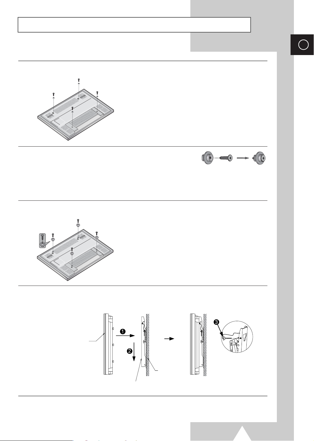
The exterior of the PDP may be different than the picture.
➢
(Assembly and installation of the plastic hanger is the same.)
1 Remove the screws from the back of the PDP.
2 Use the screws and assemble the plastic hanger.
◆ Please ask the installers to install the wall mount bracket.
☛
◆ Please be sure to check if the plastic hanger is completely secured on both the left and right
side after hanging the PDP on the wall mount bracket.
◆ Please avoid catching your fingers while installing and adjusting the angle.
◆ Please tightly secure the wall mount bracket to the wall to avoid injury from a falling PDP.
ENG
3 Tighten the screws of the plastic hanger to the back side of the PDP.
4 Put the 4 pegs on the PDP in the grooves of the wall mount bracket and pull down on the PDP (!) to
secure it to the wall mount bracket (
separated from wall mount bracket.
PDP panel
@). Tighten the screws as shown (#) so that the PDP cannot be
Wall
Wall attachment panel bracket
13
Page 14
ENG
Connecting Speakers
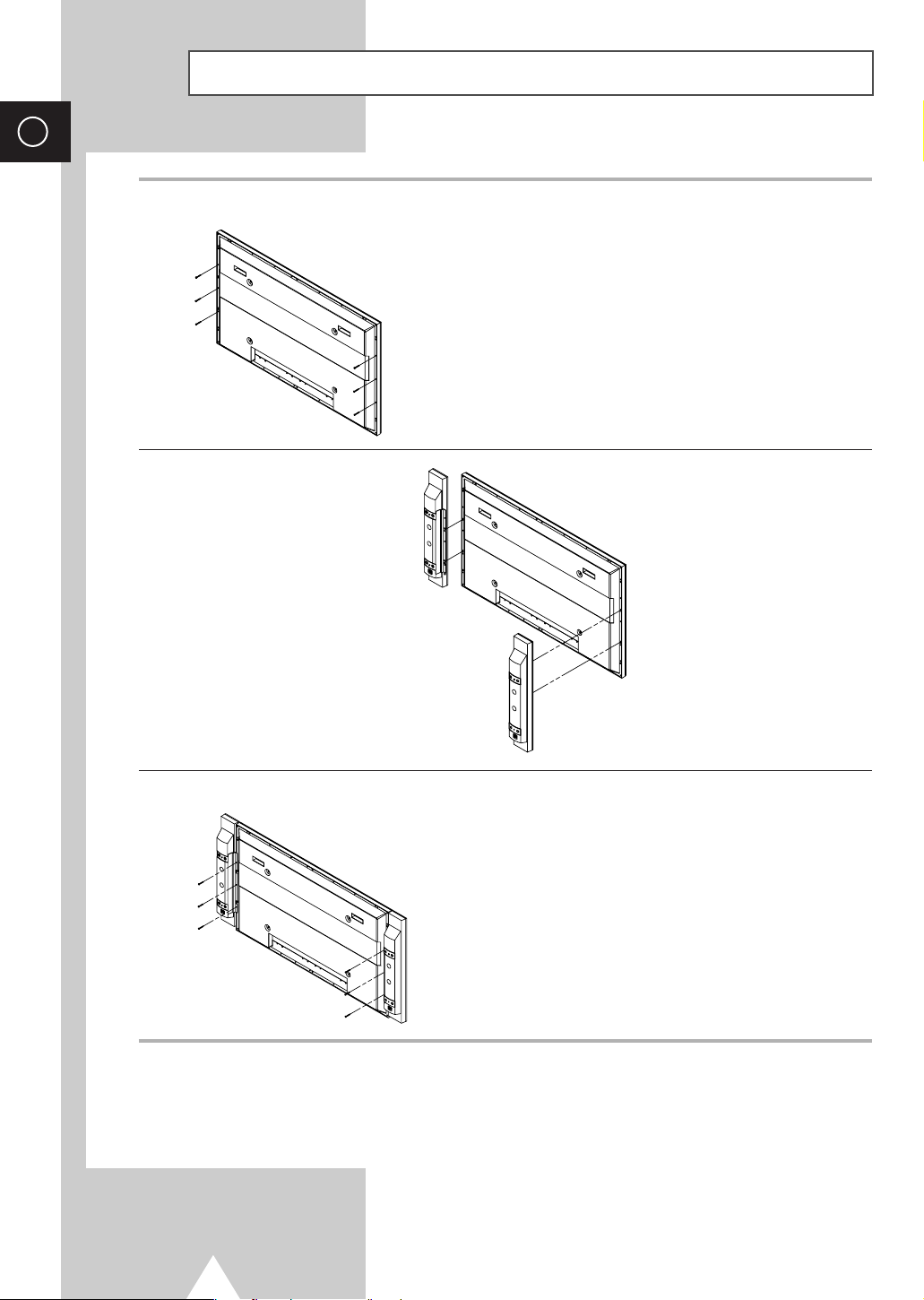
1 Remove the screws on the rear of the PDP.
2 Hang the two “T” shaped hangers
on the square holes on the rear of
the PDP.
3 Tighten the PDP and the speaker bracket using the screws removed from the PDP.
When moving your PDP, do NOT hold the speaker connected to your PDP. It may damage the
➢
bracket clamping the speaker and your PDP together and result in a drop of your PDP and a risk of
personal damage and injury.
14
Page 15
Connecting Speakers (continued)
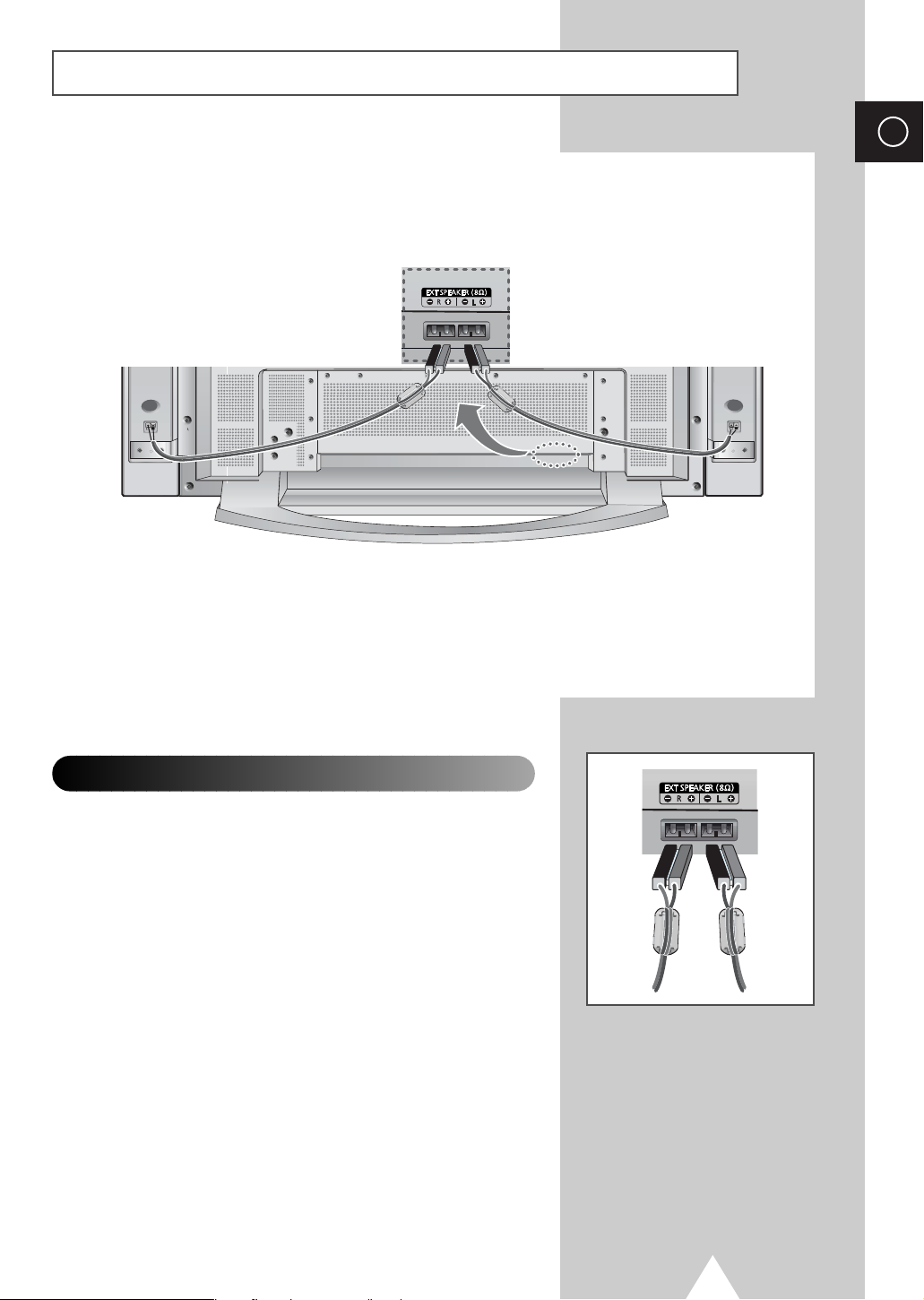
Connect the speaker audio cable to the external speaker output jack on the rear of the PDP matching
the “+” and “
-
” ends of the cable with the diagram on the PDP.
◆ The speakers MUST have to a power handling capability of 10 watts minimum
➢
(impedance 8Ω).
◆ When you connect the speaker wire to the external speaker out connector, first bind the
speaker wire round the ferrite core to secure it.
ENG
Ferrite Cores
The ferrite cores are used to attenuate undesired signals.
When connecting cables, attach one of these ferrite cores to the cable
near the connector.
15
Page 16
ENG
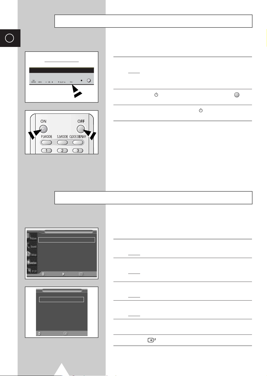
Switching On and Off
The mains lead is attached to the rear of your PDP.
Front of the PDP
1 Plug the mains lead into an appropriate socket.
2 Press the “ I / ” button on the front of the PDP (or ON ()
3 To switch your PDP off, press the “ I / ” button again (or OFF
Choosing Your Language
Result
: The Standby indicator on the front of the PDP lights up.
The main voltage is indicated on the rear of the PDP and
➢
the frequency is 50 or 60Hz.
button on the remote control) to switch the PDP on.
button on the remote control).
Function
Language English
Time
Film Mode
Move Enter Return
Language
English
Français
Deutsch
Italiano
Español
Sel. Store
16
√√
œœ
Off
When you start using your PDP for the first time, you must select the
language which will be used for displaying menus and indications.
1 Press the MENU button.
√√
Result
: The main menu is displayed.
2 Press the ▲ or ▼ button to select Function.
Result
: The options available in the
displayed.
Function group are
3 Press the √ button.
Result
: The Language option is selected.
4 Press the √ button again.
Result
: The languages available are listed.
5 Select the appropriate language by pressing the ▲ or ▼ button
repeatedly.
6 Press the button to confirm your choice.
Page 17
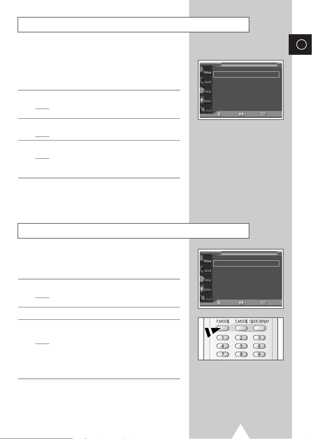
Selecting the Color System (Video or S-Video Mode)
Preset to the Video or S-Video mode by using the SOURCE button.
➢
If necessary, select the broadcasting standard which best
corresponds to your viewing requirements.
1 Press the MENU button.
Result
: The options available in the Picture group are
displayed.
2 Press the √ button.
Result
: The Color System is selected.
3 Select a required color system by pressing the œ or √ button.
Result
: The following color systems are available.
AUTO - PAL - SECAM - NTSC4.43 - NTSC3.58 PAL M - PAL N - PAL60
Picture
Color System
Mode
Adjust
Color Tone
Size Wide
Digital NR
Move Sel. Return
œœ
AUTO
œœ
Dynamic
√√
œœ
Normal
œœ
Off
ENG
√√
√√
√√
√√
Changing the Picture Mode
You can select the type of picture which best corresponds to your
viewing requirements.
1 Press the MENU button.
Result
: The options available in the Picture group are
displayed.
2 Press the √ button.
3 Press the ▲ or ▼ button to select Mode. Select the option by
pressing the
Result
You can also set these options simply by pressing the
➣
P.MODE (Picture Mode) button.
œ or √ button.
: The following modes are available depending on the
input source.
◆ Dynamic - Standard - Movie - Custom
◆ Custom - High - Middle - Low
(PC or DVI Mode)
Picture
Color System
Mode
Adjust
Color Tone
Size Wide
Digital NR
Move Sel. Return
œœ
AUTO
œœ
Dynamic
√√
œœ
Normal
œœ
Off
√√
√√
√√
√√
17
Page 18
ENG
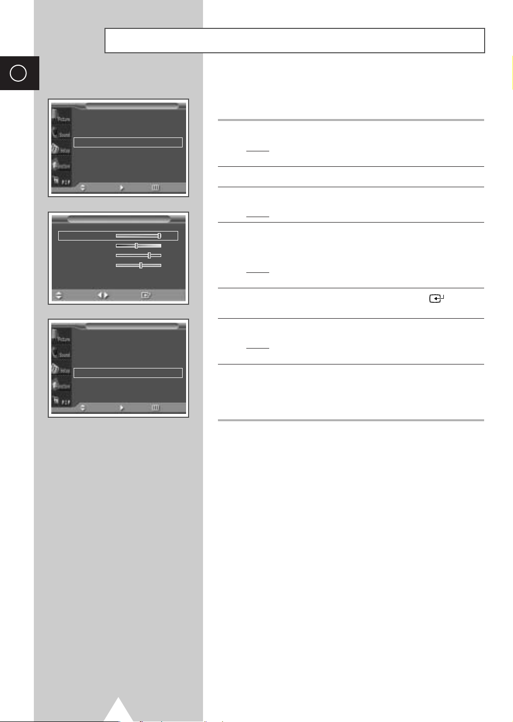
Adjusting the Picture Settings
Picture
Color System
Mode
Adjust
Color Tone
Size Wide
Digital NR
Move Enter Return
Adjust (Dynamic)
Contrast 100
Brightness 45
Sharpness 75
Color 55
Move Adjust Store
œœ
AUTO
œœ
Dynamic
√√
œœ
Normal
œœ
Off
√√
Your PDP has several settings which allow you to control picture
quality.
√√
√√
√√
1 Press the MENU button.
Result
: The options available in the Picture group are
displayed.
2 Press the √ button.
3 Press the ▲ or ▼ button to select Adjust. Press the √ button.
Result
: The Adjust menu is displayed.
4 Press the ▲ or ▼ button to select the option (Contrast,
Brightness, Sharpness, Color, Tint-NTSC only) to be
adjusted. Press the
Result
: The horizontal bar is displayed. Move the horizontal
œ or √ button.
bar’s cursor left or right by pressing the
œ or √ button.
5 When you are satisfied with the settings, press the button to
store them.
Picture
Color System
Mode
Adjust
Color Tone
Size Wide
Digital NR
Move Enter Return
œœ
AUTO
œœ
Dynamic
√√
œœ
Normal
œœ
Off
6 Press the MENU button.
√√
√√
√√
√√
Result
: The options available in the Picture group are
displayed again.
7 Press the ▲ or ▼ button to select Color Tone. Select the option
by pressing the
the following order.
If you make any changes to these settings, the picture
➣
mode is automatically switched to the
œ or √ button. The color tones are displayed in
Normal- Warm1- Warm2- Cool2- Cool1
Custom.
18
Page 19
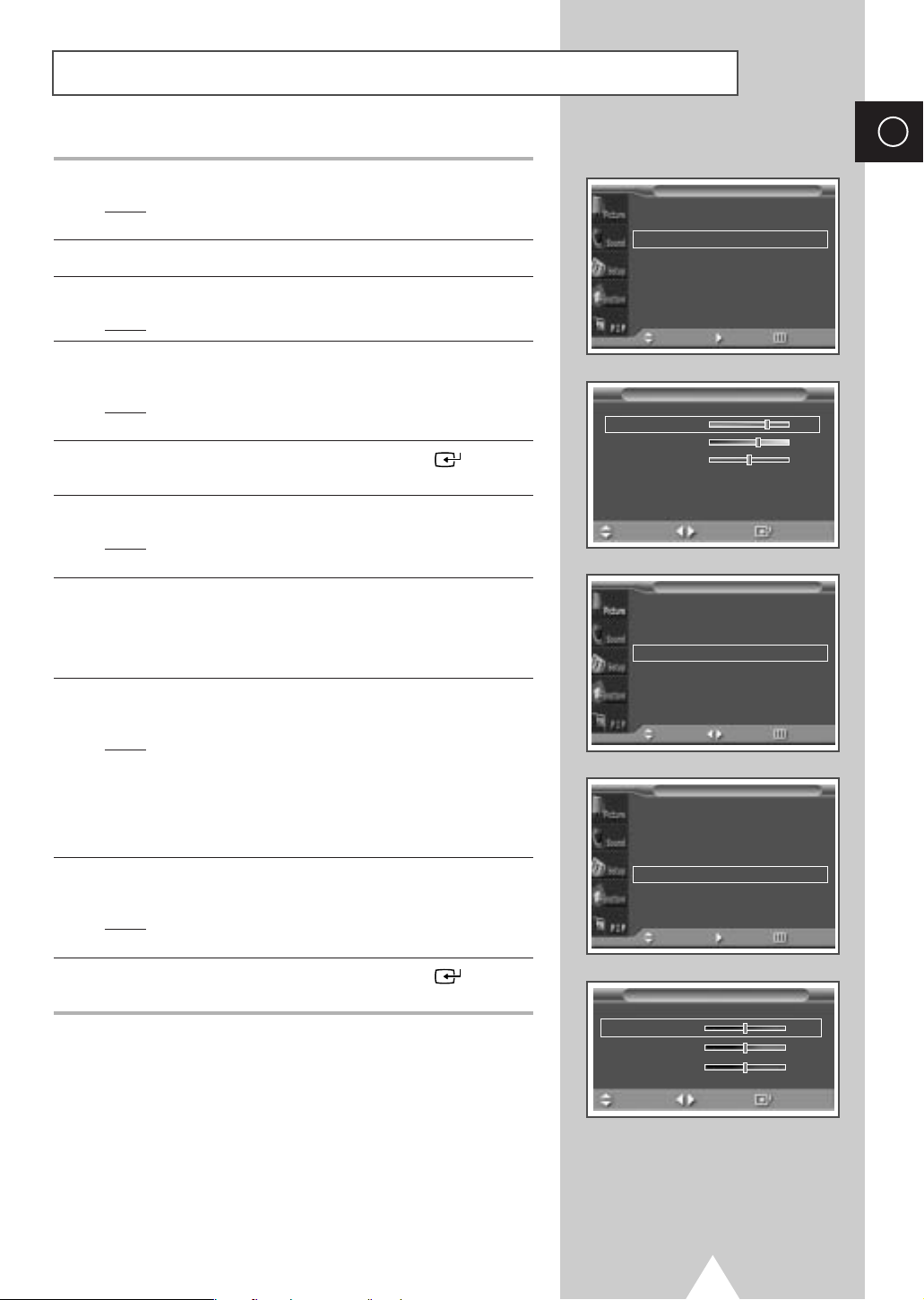
Adjusting the Picture Settings (PC or DVI Mode)
Preset to the PC or DVI mode by using the SOURCE button.
➢
ENG
1 Press the MENU button.
Result
: The options available in the Picture group are
displayed.
2 Press the √ button.
3 Press the ▲ or ▼ button to select Adjust. Press the √ button.
Result
: The Adjust menu is displayed.
4 Press the ▲ or ▼ button to select the option (Contrast,
Brightness, Sharpness) to be adjusted. Press the œ or √ button.
Result
: The horizontal bar is displayed. Move the horizontal
bar’s cursor left or right by pressing the
œ or √ button.
5 When you are satisfied with the settings, press the button to
store them.
6 Press the MENU button.
Result
: The options available in the Picture group are
displayed again.
7 Press the ▲ or ▼ button to select Color Tone. Select the option
by pressing the
the following order.
Custom (PC mode only)- Color1- Color2- Color3
œ or √ button. The color tones are displayed in
8 Press the ▲ or ▼ button to select color Adjust. Press the √
button.
Result
: The Color Adjust menu is displayed.
Picture
Picture
œœ
Custom
√√
œœ
Custom
√√
œœ
Custom
√√
œœ
Custom
√√
Mode
Adjust
Color Tone
Color Adjust
Size Wide
Move Enter Return
Adjust (Custom)
Contrast 75
Brightness 60
Sharpness 50
Move Adjust Store
Mode
Adjust
Color Tone
Color Adjust
Size Wide
Move Sel. Return
√√
√√
√√
√√
◆ When select the Color Tone to Custom, the Color
➣
Adjust
menu is displayed.
◆ The Color Adjust menu can not be selected in DVI
mode.
9 Press the ▲ or ▼ button to select the option (Red, Green, Blue) to
be adjusted. Press the
Result
: The horizontal bar is displayed. Move the horizontal
bar’s cursor left or right by pressing the
œ or √ button.
œ or √ button.
10 When you are satisfied with the settings, press the button to
store them.
Picture
Mode
Adjust
Color Tone
Color Adjust
Size Wide
Move Enter Return
Color Adjust
Red 50
Green 50
Blue 50
Move Adjust Store
œœ
Custom
√√
œœ
Custom
√√
19
√√
√√
Page 20
ENG
Selecting the Picture Size
Picture
Color System
Mode
Adjust
Color Tone
Size Wide
Digital NR
Move Sel. Return
œœ
AUTO
œœ
Dynamic
√√
œœ
Normal
œœ
Off
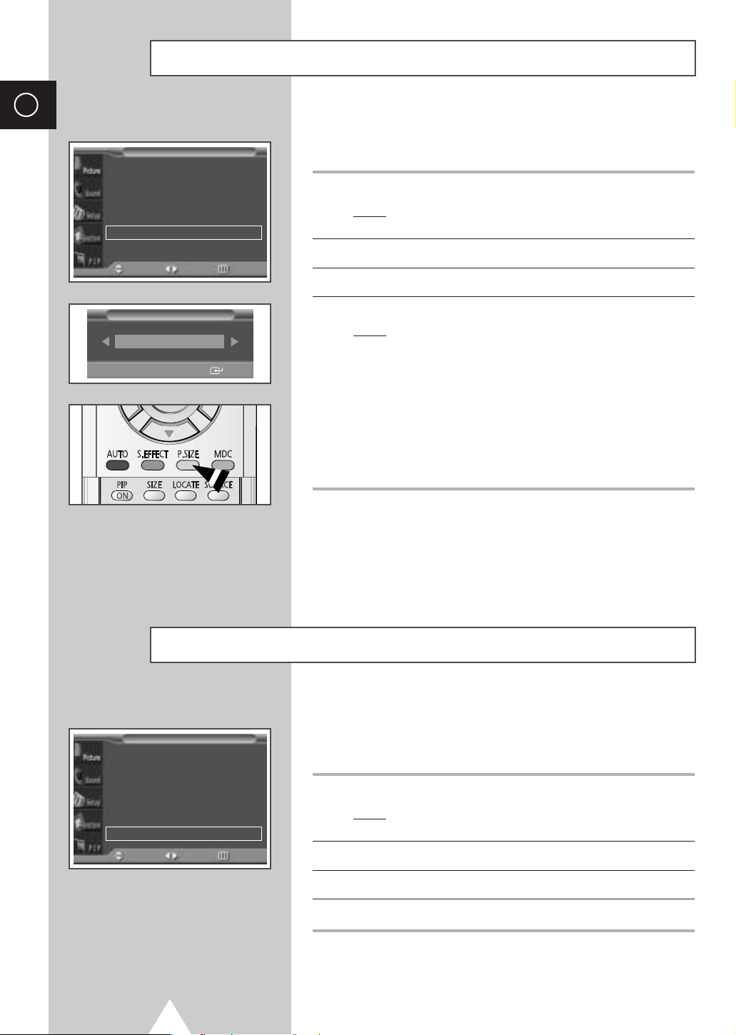
You can select the picture size which best corresponds to your
viewing requirements.
√√
√√
√√
√√
1 Press the MENU button.
Result
: The options available in the Picture group are
displayed.
2 Press the √ button.
3 Press the ▲ or ▼ button to select Size. Press the √ button.
Size
Wide
œœ √√
Sel. Store
Activating/Deactivating the Digital Noise Reduction Feature
Picture
Color System
Mode
Adjust
Color Tone
Size Wide
Digital NR
Move Sel. Return
œœ
AUTO
œœ
Dynamic
√√
œœ
Normal
œœ
Off
4 Select the option by pressing the œ or √ button.
: The following modes are available depending on the
Result
input source.
◆ Wide - Zoom1 - Zoom2 - 14:9 - Normal
◆ Wide - Panorama (Video or S-Video Mode) -
Zoom1 - Zoom2 - 14:9 - Normal
The lifting is available in the Zoom1, Zoom2 or
➣
14:9 mode by pressing the † or … button.
◆ Wide - Normal
(PC or DVI Mode)
You can also set these options simply by pressing the
➣
P.SIZE button.
If the signal received by your PDP is weak, you can activate this
feature to reduce any static and ghosting that may appear on the
screen.
√√
√√
1 Press the MENU button.
√√
√√
Result
: The options available in the Picture group are
displayed.
2 Press the √ button.
20
3 Press the ▲ or ▼ button to select Digital NR.
4 Press the œ or √ button to change the setting (On or Off).
Page 21
Freezing the Current Picture
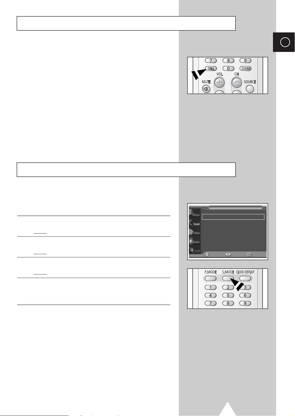
You can freeze the picture when watching a moving picture simply
by pressing the “STILL” button. To return to normal viewing, press
it again.
In the PIP mode, the main and sub pictures are stilled at
➣
the same time.
Changing the Sound Mode
ENG
You can select the type of special sound effect to be used when
watching a given broadcast.
1 Press the MENU button.
Result
: The main menu is displayed.
2 Press the ▲ or ▼ button to select Sound.
Result
:
The options available in the
Sound
group are displayed.
3 Press the √ button.
Result
: The Mode is selected.
4 Select the option by pressing the œ or √ button. The sound effects
are displayed in the following order.
Custom- Standard- Music- Movie- Speech
You can also set these options simply by pressing the
➣
S.MODE (Sound Mode) button.
Sound
Mode
Equalizer
Auto Volume
Melody
Pseudo Stereo
Virtual Surround
Move Sel. Return
œœ
Custom
√√
œœ
Off
œœ
Off
œœ
Off
œœ
Off
√√
√√
√√
√√
√√
21
Page 22
ENG
Adjusting the Sound Settings
Sound
Mode
Equalizer
Auto Volume
Melody
Pseudo Stereo
Virtual Surround
Move Enter Return
Equalizer (Custom)
R
10
œœ
Custom
√√
œœ
Off
œœ
Off
œœ
Off
œœ
Off
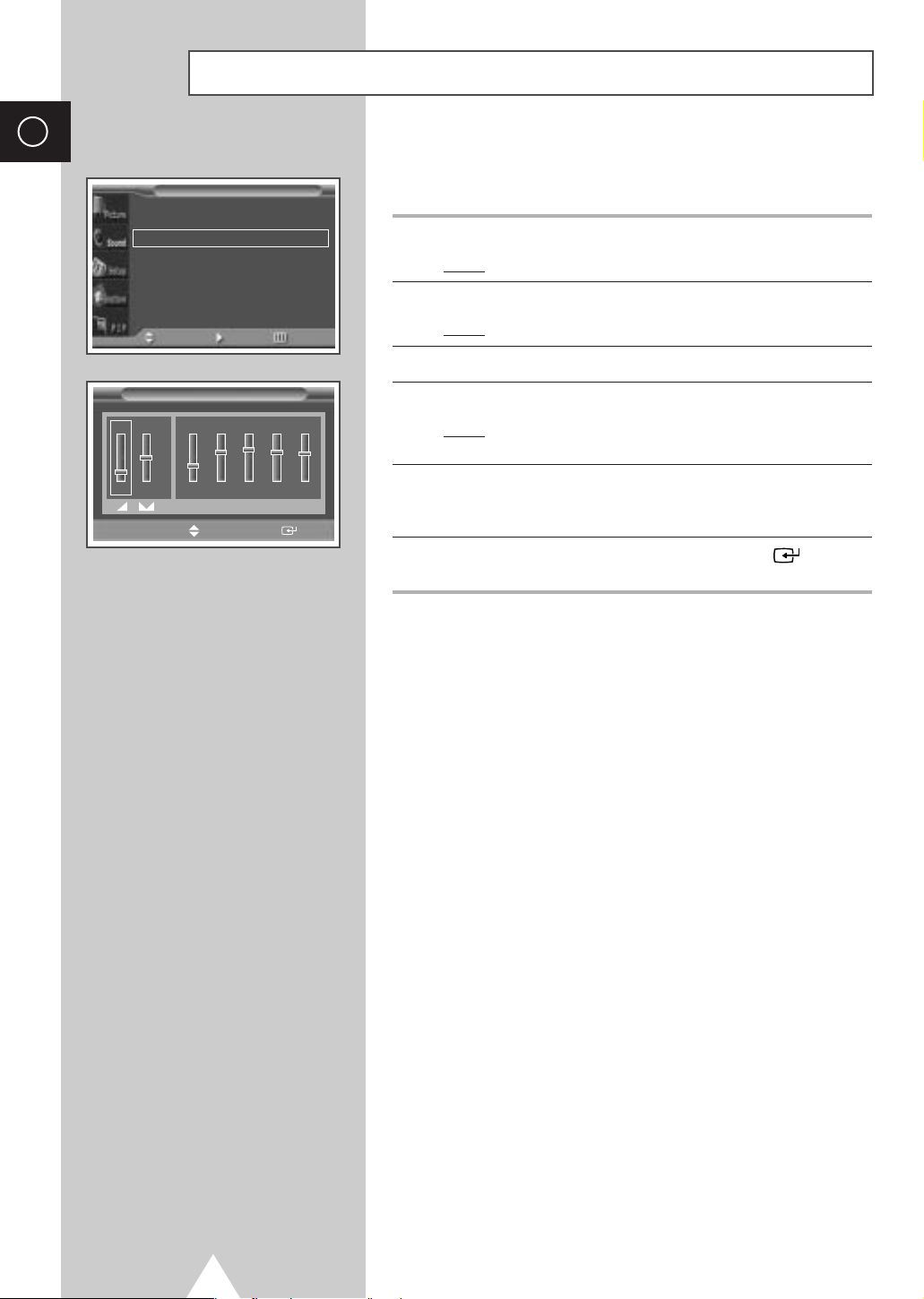
The sound settings can be adjusted to suit your personal
preferences.
√√
1 Press the MENU button.
√√
√√
√√
√√
Result
: The main menu is displayed.
2 Press the ▲ or ▼ button to select Sound.
Result
:
The options available in the
Sound
group are displayed.
3 Press the √ button.
4 Press the ▲ or ▼ button to select Equalizer. Press the √ button.
Result
: The Equalizer menu is displayed with the current
option.
œœ √√
Move
L
100 300 1K 3K 10K
Adjust Store
5 Select the option (volume, balance, equalizer) to be adjusted by
pressing the
required setting.
œ or √ button. Press the ▲ or ▼ button to reach the
6 When you are satisfied with the settings, press the button to
store them.
If you make any changes to the equalizer settings, the
➣
sound mode is automatically switched to the
Custom.
22
Page 23
Extra Sound Settings
◆ Auto Volume
Each broadcasting station has its own signal conditions,
and so it is not easy for you to adjust the volume every
time the channel is changed. This feature lets you
automatically adjust the volume of the desired channel by
lowering the sound output when the modulation signal is
high or by raising the sound output when the modulation
signal is low.
◆ Melody
You can hear clear melody sound when the PDP is
powered on or off.
◆ Pseudo Stereo / Virtual Surround
Pseudo stereo feature converts a monaural sound
signal into two identical left and right channels.
Once the
to
such as
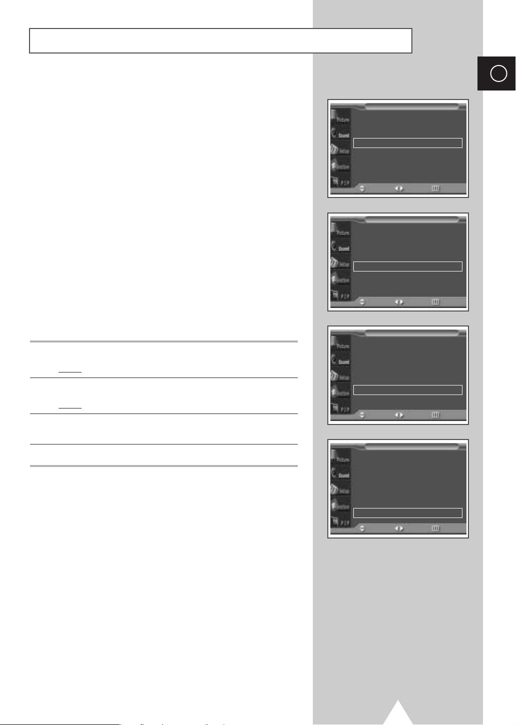
1 Press the MENU button.
Result
2 Press the ▲ or ▼ button to select Sound.
Result
3 Select the required option (Auto Volume, Melody, Pseudo
Stereo
4 Press the œ or √ button to change the setting (Off or On).
Pseudo stereo or Virtual surround is set
On or Off, these settings apply to the sound effects
Standard, Music, Movie, and Speech.
: The main menu is displayed.
:
The options available in the
Sound
group are displayed.
, Virtual Surround) by pressing the ▲ or ▼ button.
Sound
Sound
Sound
Sound
œœ
Custom
√√
œœ
Off
œœ
Off
œœ
Off
œœ
Off
œœ
Custom
√√
œœ
Off
œœ
Off
œœ
Off
œœ
Off
œœ
Custom
√√
œœ
Off
œœ
Off
œœ
Off
œœ
Off
œœ
Custom
√√
œœ
Off
œœ
Off
œœ
Off
œœ
Off
Mode
Equalizer
Auto Volume
Melody
Pseudo Stereo
Virtual Surround
Move Sel. Return
Mode
Equalizer
Auto Volume
Melody
Pseudo Stereo
Virtual Surround
Move Sel. Return
Mode
Equalizer
Auto Volume
Melody
Pseudo Stereo
Virtual Surround
Move Sel. Return
Mode
Equalizer
Auto Volume
Melody
Pseudo Stereo
Virtual Surround
Move Sel. Return
ENG
√√
√√
√√
√√
√√
√√
√√
√√
√√
√√
√√
√√
√√
√√
√√
√√
√√
√√
√√
√√
23
Page 24
ENG
Adjusting the Image Preferences (PC Mode)
Setup
Image Lock
Key Lock
Multi Control
Burning Protection
Information
Move Enter Return
Image Lock
Auto Adjustment
Frequency
Phase
Position
Zoom/Panning
Move
Frequency
œœ √√
Adjust Return
√√
œœ
Off
√√
√√
√√
√√
Enter Return
Position
Adjust
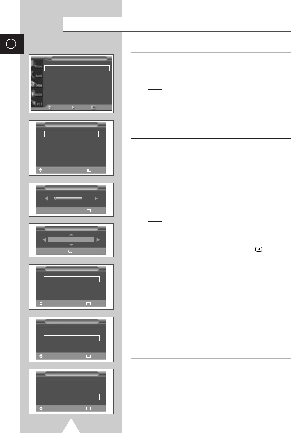
1 Press the MENU button.
: The main menu is displayed.
Result
√√
2 Press the ▲ or ▼ button to select Setup.
:
Result
The options available in the
Setup
group are displayed.
3 Press the √ button.
:
The
Result
Image Lock
is selected.
4 Press the √ button again.
: The Image Lock menu is displayed with t
Result
√√
√√
√√
√√
√√
5 Press the √ button over again.
Result
➣
Adjustment
selected.
: The screen size and frequency are automatically reset
with the
Auto Adjustment displayed.
You can also do simply by pressing the AUTO button.
he
Auto
6 Press the ▲ or ▼ button to select Frequency (or Phase). Press
the
√ button.
: The horizontal bar is displayed. Move the horizontal
0
Result
bar’s cursor left or right by pressing the
œ or √ button.
7 When you are satisfied with the settings, press the MENU button.
: The Image Lock menu is displayed again.
Result
8 Press the ▲ or ▼ button to select Position. Press the √ button.
Adjust the screen position by pressing the
▲, ▼, œ, or √ button.
Store
Zoom/Panning
Zoom 1
Panning
Reset
Move
Move
Move
œœ √√
Adjust Return
Zoom/Panning
Zoom 1
Panning
Reset
√√
Enter Return
Zoom/Panning
Zoom 1
Panning
Reset
√√
Enter Return
9 When you are satisfied with the setting, press the button to
store.
10 Press the MENU button.
: The Image Lock menu is displayed again.
Result
√√
√√
11 Press the ▲ or ▼ button to select Zoom/Panning. Press the √
button.
: The Zoom/Panning menu is displayed with t
Result
he
Zoom
selected.
You can also do simpley by pressing the ZOOM button.
➣
12 Press the œ or √ button to reach the required magnification.
√√
√√
√√
√√
13 Press the ▲ or ▼ button to select Panning. Move the magnified
picture to required position by using pressing the
button.
Press the ▲ or ▼ button to select Reset. Press the √ button.
➢
The zoom and panning settings are replaced with the factory
default values.
The Panning and Reset menus can be used when value of
➢
Zoom is more than 1.
▲, ▼, œ, or √
24
Page 25
Locking the Control buttons
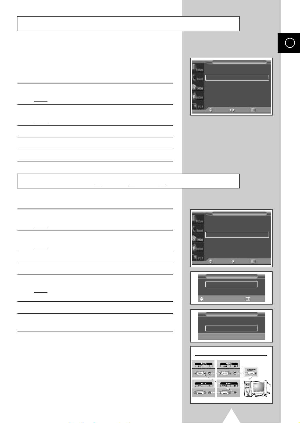
This feature allows you to lock the PDP so that it cannot be
switched on via the front panel. It can, however, still be switched
on via the remote control. Thus, by keeping the remote control
away from unauthorised users.
1 Press the MENU button.
Result
: The main menu is displayed.
Screen Adjust
Key Lock
Multi Control
Burning Protection
Setup
ENG
√√
œœ
√√
Off
√√
√√
2 Press the ▲ or ▼ button to select Setup.
Result
:
The options available in the
Setup
group are displayed.
3 Press the √ button.
4 Press the ▲ or ▼ button to select Key Lock.
5 Press the œ or √ button to change the setting (On or Off).
Setting the MDC (M
ultiple Display Control)
1 Press the MENU button.
Result
: The main menu is displayed.
2 Press the ▲ or ▼ button to select Setup.
Result
:
The options available in the
Setup
group are displayed.
3 Press the √ button.
4 Press the ▲ or ▼ button to select Multi Control.
5 Press the √ button.
Result
: The Multi Control menu is displayed with t
Setup
selected.
he
6 Select the ID setup number by pressing the œ or √ button.
7 Press the ▲ or ▼ button to select ID Input. Enter ID input
number by using the numeric buttons.
To operate the multi control function, PDP1 and PDP2 should be
➢
set in the ID Setup mode. When entering the ID Input number of
PDP1 while the PDP is set in the ID Input mode, only PDP1 is
switched to the Menu screen and you can operate the remote
control. At this time, PDP2 doesn't operate with the remote control
and displays the standby mode of ID Input.
ID
Move Sel. Return
Setup
Screen Adjust
Key Lock
Multi Control
Burning Protection
Move Enter Return
Multi Control
ID Setup 01
ID Input
Move
Example for Multiple Display Control connections
œœ √√
Multi Control
ID Setup 01
ID Input
Enter ID Input Number
√√
œœ
√√
Off
√√
√√
--
Adjust Return
--
For further details, refer to the MDC program guide.
➢
The PS42D4ST model uses the same MDC program CD used for
➢
PS42P3ST model.
25
Page 26

ENG
Protecting the Screen Burning
Setup
Key Lock
Multi Control
Burning Protection
Move Enter Return
œœ
Off
√√
√√
You can prevent the residual image of the PDP.
√√
1 Press the MENU button.
Result
: The main menu is displayed.
2 Press the ▲ or ▼ button to select Setup.
Result
:
The options available in the
Setup
group are displayed.
3 Press the √ button.
Burning Protection
Pixel Shift
Signal Pattern
All White
Move
Pixel Shift
Set
Horizontal Dot 2
Vertical Line 4
Time 4 MIN
Move
Burning Protection
Pixel Shift
Signal Pattern
All White
Move
Burning Protection
Pixel Shift
Signal Pattern
All White
Move
√√
œœ
œœ
√√
Enter Return
œœ
œœ √√
Sel. Return
√√
œœ
œœ
œœ √√
Sel. Return
√√
œœ
œœ
œœ √√
Sel. Return
Off
Off
On
Off
Off
Off
Off
4 Press the ▲ or ▼ button to select Burning Protection.
5 Press the √ button.
√√
√√
Result
: The Burning Protection menu is displayed with
t
he
Pixel Shift
selected.
6 Press the √ button again.
Result
: The Pixel Shift menu is displayed with t
he
Set
selected.
You can also do simply by pressing the S.EFFECT button.
√√
➣
7 Set to On by pressing the œ or √ button for making the screen
move per regular hour and preventing the residual image.
8 Select the option (Horizontal Dot, Vertical Line, Time) to be
adjusted by pressing the
to reach the required setting.
Optimum condition for pixel shift;
➣
√√
√√
Horizontal Dot
Vertical Line
Time
▲ or ▼ button. Press the œ or √ button
2
4
4MIN
9 When you are satisfied with the settings, press the MENU button.
Result
: The Burning Protection menu is displayed again.
√√
√√
10 Press the ▲ or ▼ button to select Signal Pattern. Set to On by
pressing the
œ or √ button for removing the residual image.
11 Press the ▲ or ▼ button to select All White. Set to On by
pressing the
making the screen white.
œ or √ button for removing the residual image after
26
The Signal Pattern and All White feature are
➣
effective after working for a long time.
Page 27
Displaying the PC Information
ENG
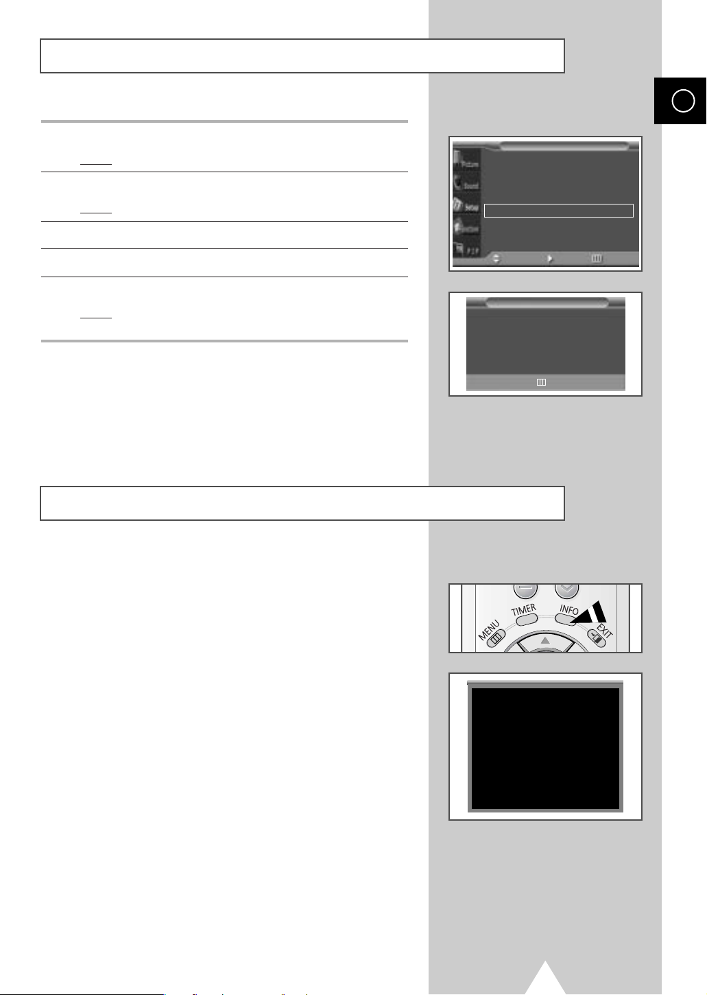
1 Press the MENU button.
Result
: The main menu is displayed.
2 Press the ▲ or ▼ button to select Setup.
Result
:
The options available in the
Setup
group are displayed.
3 Press the √ button.
4 Press the ▲ or ▼ button to select Information.
5 Press the √ button.
Result
: The resolution, vertical frequency and horizontal
frequency are displayed.
Displaying the Setting Information
Setup
Return
œœ
Off
√√
√√
√√
Key Lock
Multi Control
Burning Protection
Information
Move Enter Return
PC Information
Resolution 1024x768
V Frequency 60
H Frequency 48
√√
You can view the setting status you select by pressing the “INFO”
button on the remote control.
Mode Video
Picture Dynamic
Sound Custom
Clock 11:45
27
Page 28
ENG
Setting and Displaying the Current T ime
Function
Language English
Time
Film Mode
Move Enter Return
√√
œœ
Off
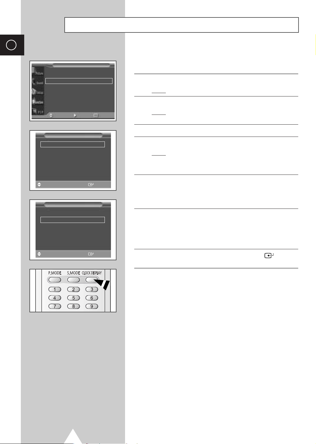
You can set the clock so that the current time is displayed. You must
also set the time if you wish to use the automatic on or off timers.
1 Press the MENU button.
√√
Result
: The main menu is displayed.
2 Press the ▲ or ▼ button to select Function.
Result
: The options available in the Function group are
displayed.
Time
Clock
Clock Display
Timer
On Time Volume 10
On Time
Off Time
Move
Clock
Clock Display
Timer
On Time Volume 10
On Time
Off Time
Move
œœ
œœ
œœ √√
Sel. Store
Time
œœ
œœ
œœ √√
Sel. Store
11:35
Off
Off
--:--
--:--
11:35
Off
Off
--:--
--:--
3 Press the √ button.
4 Press the ▲ or ▼ button to select Time. Press the √ button.
√√
√√
Result
: The Time menu is displayed with the Clock option
selected.
You can also do simply by pressing the TIMER button.
➣
5 Press the œ or √ button to move to the hour or minute.
Set the hour or minute by pressing the
Set the clock first! If you have not yet set the clock, you can
➣
not set other options of the
√√
√√
6 Press the ▲ or ▼ button to select Clock Display.
Set to
On by pressing the œ or √ button for displaying the current
time.
You can also do simply by pressing the CLOCK DISPLAY
➣
button.
▲ or ▼ button.
Time menu.
7 When you are satisfied with the settings, press the button to
store them.
28
Page 29
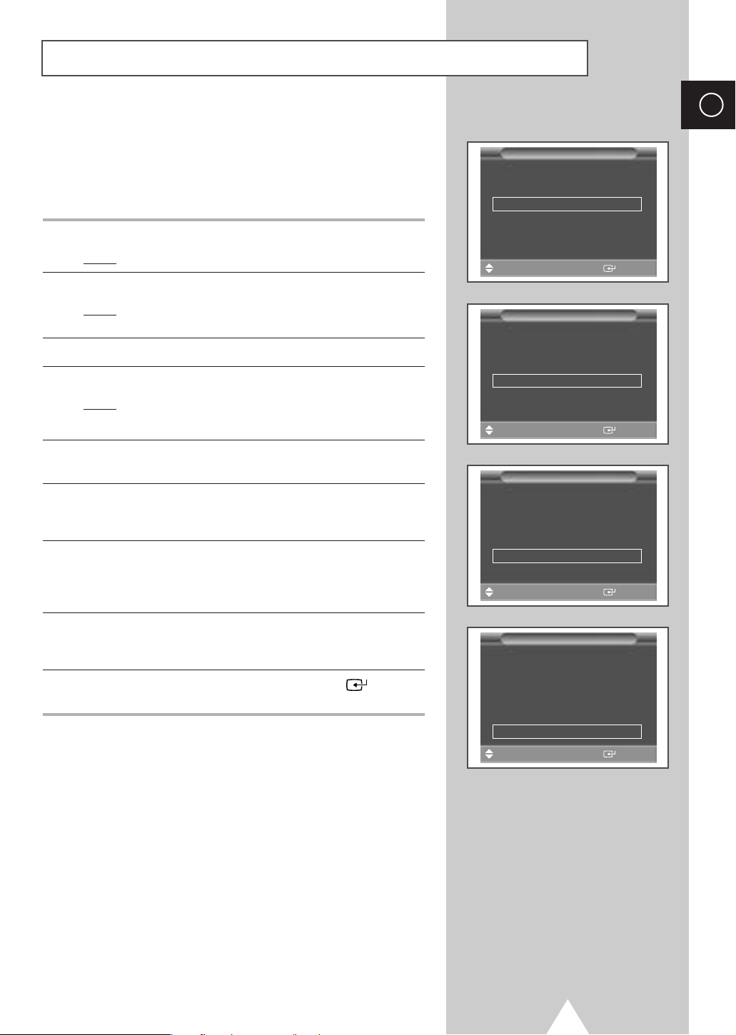
Switching On and Off Automatically
You can set the on or off time so that the PDP will:
◆ Switch on automatically and tune to the volume of your
choice at the time you select
◆ Switch off automatically at the time you select
1 Press the MENU button.
Result
: The main menu is displayed.
2 Press the ▲ or ▼ button to select Function.
Result
: The options available in the Function group are
displayed.
3 Press the √ button.
4 Press the ▲ or ▼ button to select Time. Press the √ button.
Result
: The Time menu is displayed.
You can also do simply by pressing the TIMER button.
➣
5 Press the ▲ or ▼ button to select Timer. Set to On by pressing the
œ or √ button for switching on or off automatically.
6 Press the ▲ or ▼ button to select On Time Volume. Set the
volume by pressing the
your choice at the time switching on.
7 Press the ▲ or ▼ button to select On Time. Press the œ or √
button to move to the hour or minute. Set the time at which you
wish the PDP to be switched on automatically by pressing the
or ▼ button.
œ or √ button for tuning to the volume of
▲
Time
Clock
Clock Display
Timer
On Time Volume 10
On Time
Off Time
Move
Clock
Clock Display
Timer
On Time Volume 10
On Time
Off Time
Move
Clock
Clock Display
Timer
On Time Volume 10
On Time
Off Time
Move
œœ √√
œœ
œœ
œœ √√
Sel. Store
Time
œœ
œœ
Adjust Store
Time
œœ
œœ
œœ √√
Sel. Store
11:35
Off
Off
--:--
--:--
11:35
Off
Off
--:--
--:--
11:35
Off
Off
06:00
--:--
ENG
√√
√√
√√
√√
√√
√√
8 Press the ▲ or ▼ button to select Off Time. In the same above,
set the time at which you wish the PDP to be switched off
automatically.
9 When you are satisfied with the settings, press the button to
store them.
Absent Power Off
➣
Your PDP will automatically be turned off, if you do not
operate any controls during the 3 hours when the “
is set to “
feature will not work when the “
On” and the “On Time” is set. However, this
Off Time” is set.
This feature prevents a leakage accident or overheating,
caused by your PDP left on for an extended time (when
you are away on holiday, for example).
Timer”
Time
Clock
Clock Display
Timer
On Time Volume 10
On Time
Off Time
Move
œœ
œœ
œœ √√
Sel. Store
29
11:35
Off
Off
06:00
23:30
√√
√√
Page 30
ENG
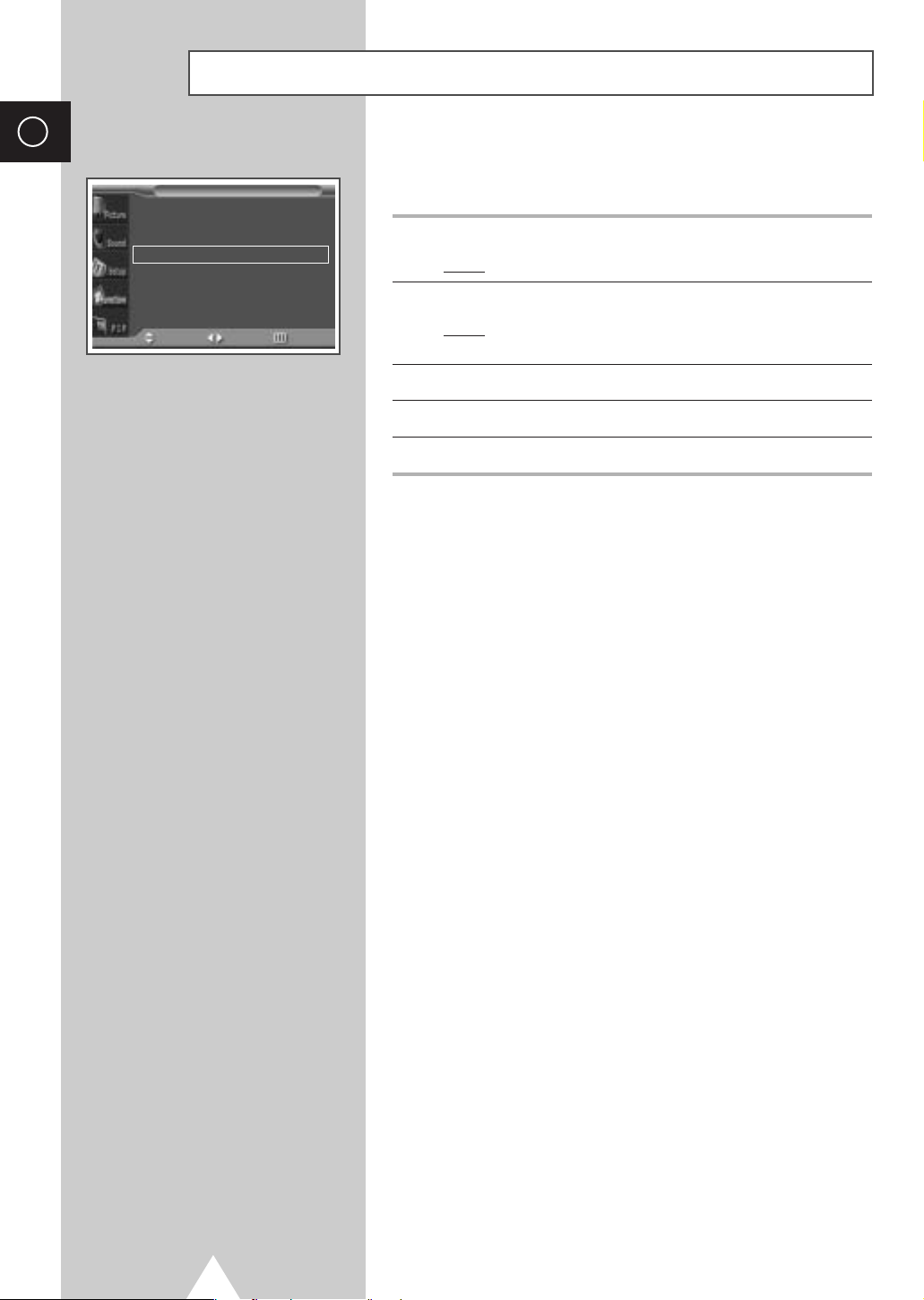
Setting the Film Mode
Function
Language English
Time
Film Mode
Move Sel. Return
√√
œœ
Off
When a video input source is from a film such as movies, this feature
identifies the source and changes to the corresponding screen.
1 Press the MENU button.
√√
Result
: The main menu is displayed.
2 Press the ▲ or ▼ button to select Function.
Result
: The options available in the Function group are
displayed.
3 Press the √ button.
4 Press the ▲ or ▼ button to select Film Mode.
5 Press the œ or √ button to change the setting (On or Off).
◆ If video source is not film, set to Off.
➣
◆ Available in Video, S-Video, and Component (480i)
modes.
30
Page 31
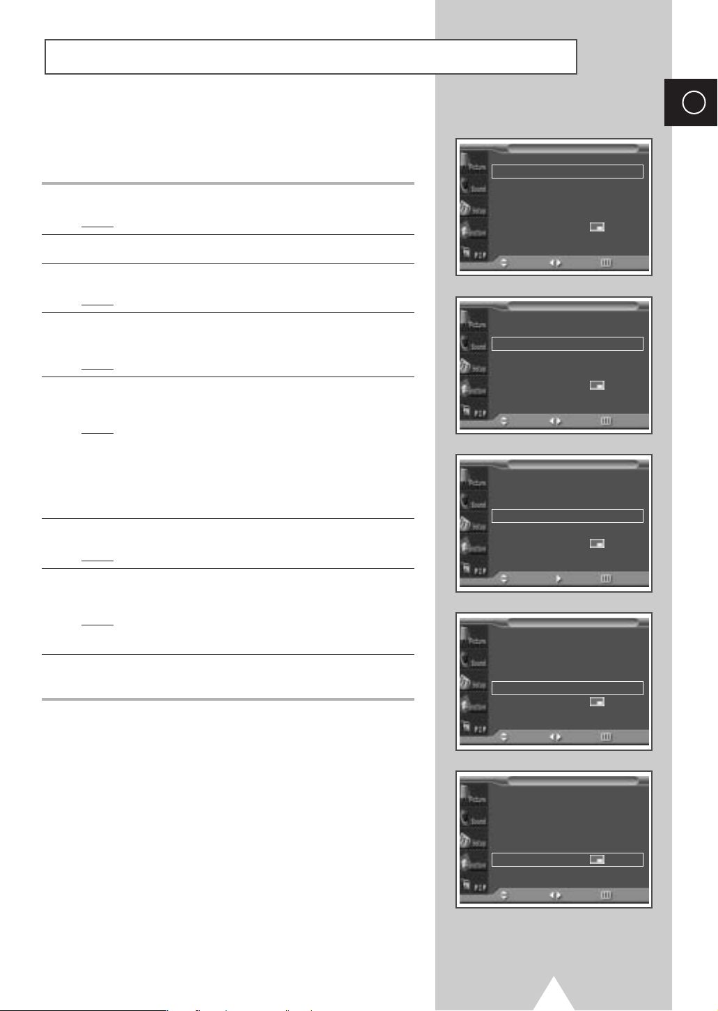
Viewing the Picture In Picture (PIP)
You can display a sub picture within the main picture. In this way
you can monitor the video input from any connected devices while
monitoring other video input.
1 Press the MENU button.
Result
: The main menu is displayed.
2 Press the ▲ or ▼ button to select PIP.
3 Press the √ button.
Result
: The PIP option is selected.
4 Set to On by pressing the œ or √ button for activating the PIP
feature.
Result
: The options available in the PIP group are displayed.
5 Press the ▲ or ▼ button to select Sel.. Select a source of the sub
picture by pressing the
Result
: The sources are displayed in the following order:
Video - S-Video - Component - PC - DVI
For further details about selecting a source, refer to
➣
“Selecting the source of sub picture depending on the source
of main picture” on page 32.
6 Press the ▲ or ▼ button to select Swap. Press the √ button.
Result
: The main picture and sub picture are interchanged.
7 Press the ▲ or ▼ button to select Size. Select a size of the sub
picture by pressing the
Result
: The sizes are displayed in the following order:
Large- Small- Double1- Double2
8 Press the ▲ or ▼ button to select Locate. Select a location of the
sub picture by pressing the
œ or √ button.
œ or √ button.
œ or √ button.
PIP
PIP
PIP
PIP
œœ
On
œœ
Video
√√
œœ
Large
œœ √√
œœ
Main
œœ
On
œœ
Video
√√
œœ
Large
œœ √√
œœ
Main
œœ
On
œœ
Video
√√
œœ
Large
œœ √√
œœ
Main
œœ
On
œœ
Video
√√
œœ
Large
œœ √√
œœ
Main
PIP
Sel.
Swap
Size
Position
Sound Sel.
Move Sel. Return
PIP
Sel.
Swap
Size
Position
Sound Sel.
Move Sel. Return
PIP
Sel.
Swap
Size
Position
Sound Sel.
Move Enter Return
PIP
Sel.
Swap
Size
Position
Sound Sel.
Move Sel. Return
ENG
√√
√√
√√
√√
√√
√√
√√
√√
√√
√√
√√
√√
√√
√√
√√
√√
PIP
PIP
Sel.
Swap
Size
Position
Sound Sel.
Move Sel. Return
œœ
On
œœ
Video
√√
œœ
Large
œœ √√
œœ
Main
31
√√
√√
√√
√√
Page 32
ENG
Viewing the Picture In Picture (PIP) (continued)
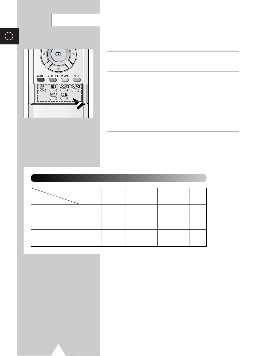
Easy functions of remote control.
Buttons Feature
PIP ON Used to activate or deactivate the PIP feature directly.
SIZE Used to select a size of sub picture (Large, Small,
Double1, Double2).
LOCATE Used to move the sub picture counterclockwise.
SOURCE Used to assign a source of sub picture.
SWAP Used to interchange the main picture and the sub
S.SEL Used to listen the sound of the sub picture.
Selecting the source of sub picture depending on the source of main picture
Main picture
Sub picture
Video
S-Video
Component
PC
DVI
Video S-Video PC
✔
✔
✔
✔
✔
✔
✔
✔
picture.
✔
✔
✔
✔
DVIComponent
✔
✔
32
Page 33
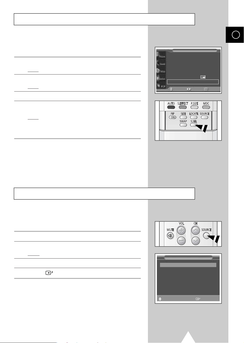
Listening to the Sound of the Sub Picture
During the PIP feature is activating, you can listen to the sound of the
sub picture.
1 Press the MENU button.
Result
: The main menu is displayed.
2 Press the ▲ or ▼ button to select PIP.
Result
: The options available in the PIP group are displayed.
3 Press the √ button.
4 Press the ▲ or ▼ button to select Sound Sel.. Set to Sub by
pressing the
Result
➣
œ or √ button.
: You can listen to the sound of the sub picture.
◆ To listen the sound of current main picture, set to Main.
◆ You can also do simply by pressing the S.SEL button.
PIP
PIP
Sel.
Swap
Size
Position
Sound Sel.
Move Sel. Return
œœ
On
œœ
Video
√√
œœ
Large
œœ √√
œœ
Sub
ENG
√√
√√
√√
√√
Viewing Pictures From External Sources
Once you have connected up your various audio and video systems,
you can view different sources by selecting the appropriate input.
1 Check that all the necessary connections have been made.
2 Switch your PDP on, then press the SOURCE button.
Result:
3 Press the ▲ or ▼ button to select the required input source.
4 Press the button to store.
➣
The input sources available are displayed.
◆ If you change the external source while viewing,
pictures might take a short period of time to be
switched.
AV Input
Video Connected
S-Video Not Connected
Component Connected
PC Not Connected
DVI Not Connected
Sel. Store
33
Page 34
ENG
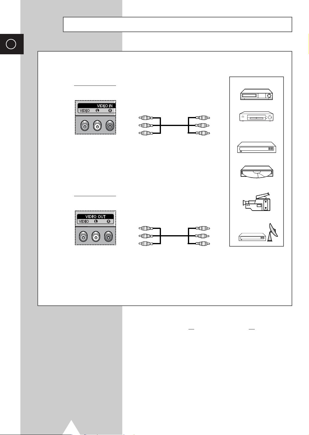
Connecting to the Audio/Video Input
The "VIDEO IN" connectors are used for the equipment with an Composite Video output, such as
video game devices or video disc players.
Rear of the PDP
(Input)
The "VIDEO OUT" connectors are used for the equipment with an
Composite Video input, such as a camcorder or VCR.
Rear of the PDP
(Output)
VCR
①
DVD
Decoder /
Video game device
Video disc player
Camcorder
Satellite receiver
②
①
If you have a second VCR and wish to copy cassettes tape, connect the source VCR to
the target VCR to
②
When you wish to record a programme, connect the receiver to
OUT
”
so that you can redirect the signal from
34
“VIDEO OUT”
so that you can redirect the signal from
“VIDEO IN”
Whenever you connect an audio or video system to your
☛
PDP, ensure that all
Refer to the documentation supplied with your equipment
for detailed connection instructions and associated safety
precautions.
to
“VIDEO OUT”
“VIDEO IN”
“VIDEO IN”
.
elements are switched off.
to
“VIDEO OUT”
and the VCR to
“VIDEO IN”
“VIDEO
and
.
Page 35
Connecting to the S-Video Input
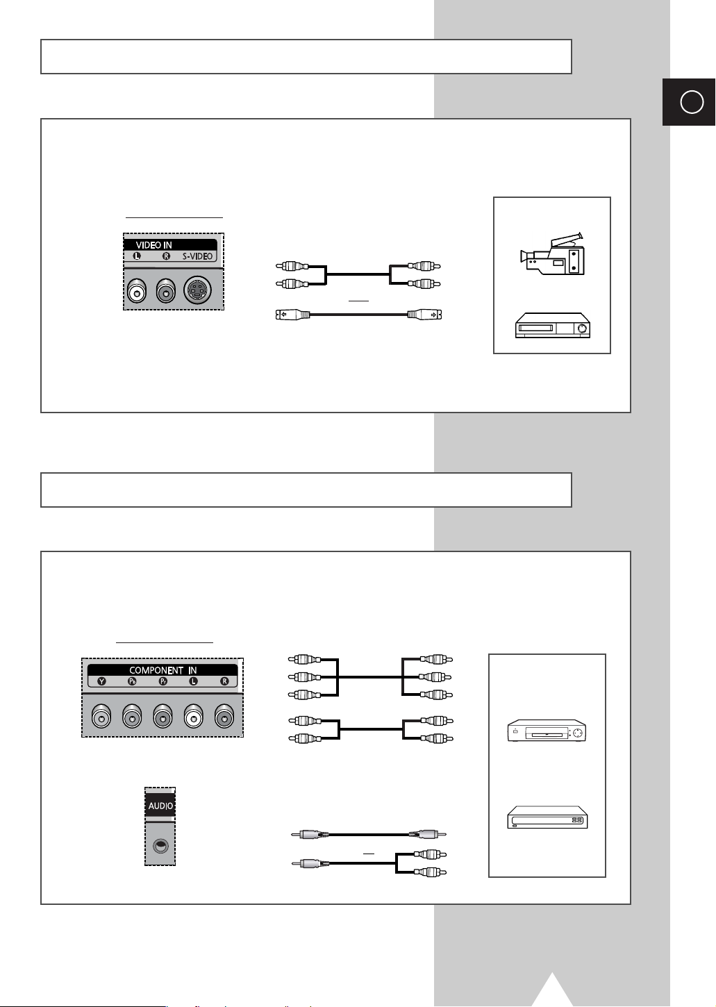
The S-VIDEO and RCA (AUDIO-L/R) connectors are used for equipment with an S-Video output,
such as a camcorder or VCR.
ENG
Rear of the PDP
Camcorder
①
and
①
To play picture and sound, both the S-VIDEO and RCA connectors must be used.
VCR
Connecting to the DVD/DTV RECEIVER Input
The “COMPONENT IN” (and “AUDIO”) connectors are used for equipment with a DVD/ DTV
RECEIVER output. (480i, 480p, 720, 1080i)
Rear of the PDP
Y / Pb / Pr
DVD
L / R
Digital Set-Top Box
or
35
Page 36
ENG
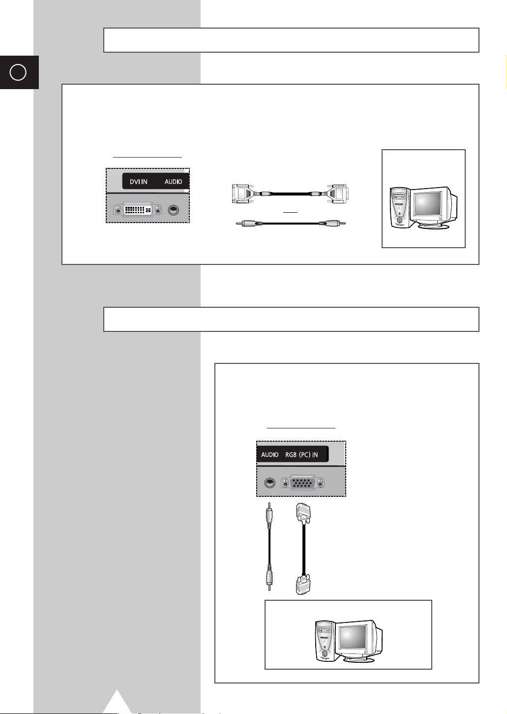
Connecting to the DVI Input
The “DVI IN” (video) and “AUDIO” connectors are used for equipment with a DVI output.
Rear of the PDP
Personal Computer
and
Connecting to the RGB(PC) Input
The “RGB(PC) IN” and “AUDIO” connectors are used for
interfacing with your PC.
Rear of the PDP
Personal Computer
36
Page 37
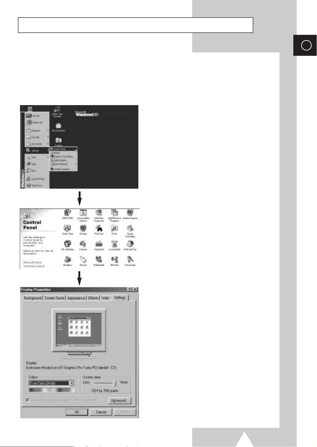
Setting up Your PC Software (Windows only)
The Windows display-settings for a typical computer are shown below. But the actual screens on your
PC will probably be different, depending upon your particular version of Windows and your particular
video card. But even if your actual screens look different, the same, basic set-up information will apply
in almost all cases. (If not, contact your computer manufacturer or Samsung Dealer.)
On the windows screen, select in the following
sequence:
Start ➞ Settings ➞ Control Panel.
ENG
When the control panel screen appears, click on
Display and a display dialog-box will appear.
Select the Settings tab in the display dialog-box.
The two key variables that apply the PDP-PC interface
are “Resolution” and “Colours”.
The correct settings for these two variables are:
◆ Size (sometimes called “Resolution”)
-
640 x 480 pixels
◆ Colour
24-bit colour (might also be expressed as “16
million colours”)
Shown at left is a typical screen for “Display” dialog
box.
If a vertical-frequency option exists on your display
settings dialog box, the correct value is
Otherwise, just click
OK and exit the dialog box.
60 Hz.
37
Page 38
ENG
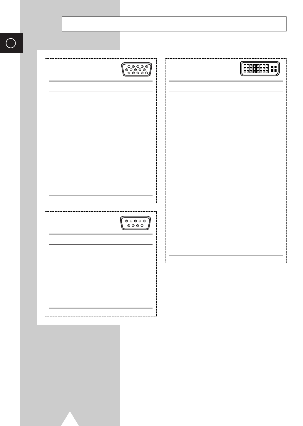
Pin Configurations
RGB(PC) Input Connector
(15Pin)
Pin RGB(PC) IN
1 Red (R)
2 Green (G)
3 Blue (B)
4 Grounding
5 Grounding (DDC)
6 Red (R) Grounding
7Green (G) Grounding
8 Blue (B) Grounding
9 Reserved
10 Sync Grounding
11 Grounding
12 Data (DDC)
13 Horizontal sync.
14 Vertical sync.
15 Clock (DDC)
RS232C Connector
(9Pin)
Pin Signal
1Carrier Detect
2 Receive Data
3 Transmit Data
4 Data Terminal Ready
5 System Ground
6 Data Set Ready
7 Request to Send
8 Clear to Send
9 Ring Indicator
DVI Input Connector
(24Pin)
Pin Signal
1T.M.D.S. Data22 T.M.D.S. Data2+
3 T.M.D.S. Data2/4 Shield
4T.M.D.S. Data45 T.M.D.S. Data4+
6 Clock (DDC)
7Data (DDC)
8 Not Connected
9T.M.D.S. Data110 T.M.D.S. Data1+
11 T.M.D.S. Data1/3 Shield
12 T.M.D.S. Data313 T.M.D.S. Data3+
14 +5V Power
15 5V Grounding
16 Hot Plug Detect
17 T.M.D.S. Data018 T.M.D.S. Data0+
19 T.M.D.S. Data0/5 Shield
20 T.M.D.S. Data521 T.M.D.S. Data5+
22 T.M.D.S. Clock Shield
23 T.M.D.S. Clock+
24 T.M.D.S. Clock-
38
Page 39
39
ENG
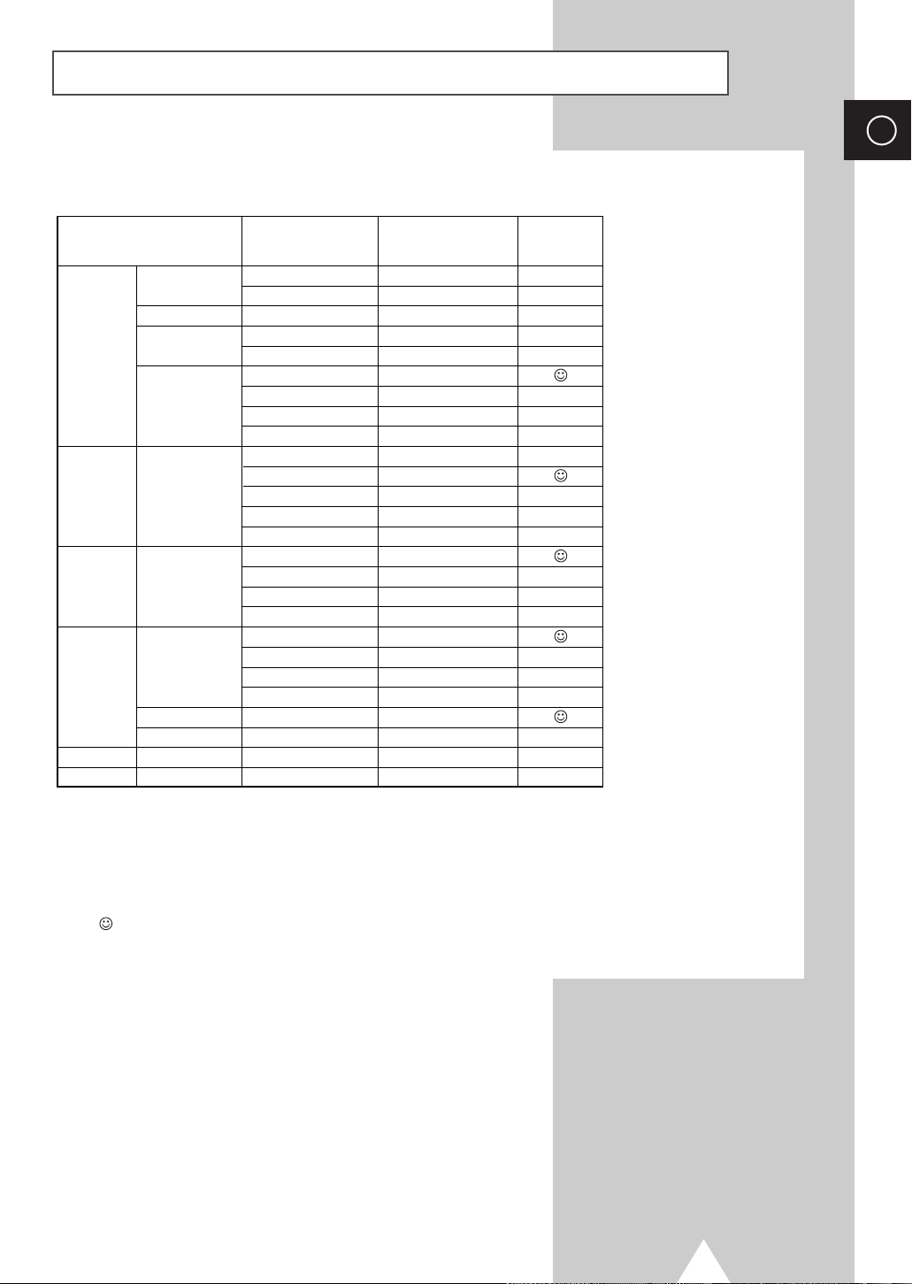
Input Mode (PC/DVI)
Both screen position and size will vary depending on the type of PC monitor and its resolution.
The table below shows all of the display modes that are supported:
◆ “❉” mode does not work with DVI mode.
◆ The interlace mode is not supported.
◆ The PDP might operate abnormally if a non-standard video format is selected.
◆ The 852 x 480 mode is only supported by a particular video card (PIXEL PERFECT made by IMAGINE
GRAPHICS Ltd.
).
◆ A “ ” mark means that this mode is recommended.
Resolution
640 x 350
640 x 400
720 x 400
640 x 480
800 x 600
1024 x 768
848 x 480
852 x 480
1152 x 864
1280 x 1024
1280 x 768
Horizontal
frequency (kHz)
Vertical
frequency (Hz)
PS42D4ST
VGA
SVGA
XGA
WVGA
SXGA
WXGA
70
85
85
70
85
60
72
75
85
56
60
72
75
85
60
70
75
85
60
72
75
85
60
75
60
60
31.5
37.9
37.9
31.5
37.9
31.5
37.9
37.5
43.3
35.2
37.9
48.1
46.9
53.7
48.4
56.5
60.6
68.7
29.8
35.1
36.0
37.0
31.8
67.5
64.0
47.7
❉
❉
❉
Page 40
ENG
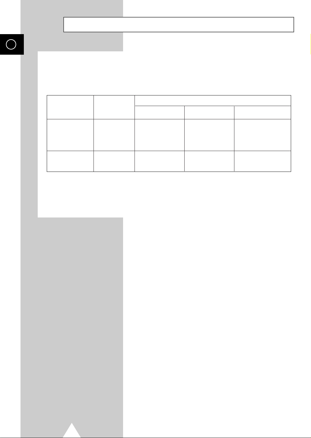
Power Saver (PC mode only)
This monitor has a built-in power management system called Power Saver. This power management
system saves energy by switching your monitor into a low-power mode when it has not been used for a
certain amount of time. This power management system operates with a VESA DPMS compliant video
card installed in your computer. You use a software utility installed on your computer to set up this
feature. See the table below for details.
State
Horizontal Sync
Vertical Sync
Video
Power Indicator
◆ This monitor automatically returns to normal operation when horizontal and vertical sync return.
◆ This occurs when moving the computer’s mouse or pressing a key on the keyboard.
◆ For energy conservation, turn your monitor OFF when it is not needed, or when leaving it unattended for long
periods.
Normal
Operation
Active
Active
Active
Off
Standby Mode
Inactive
Active
Blanked
Red Blinking
(1 sec Interval)
Power-saving Function Mode
Suspend Mode
Position A1
Active
Inactive
Blanked
Red Blinking
(1 sec Interval)
Power-off Mode
Position A2
Inactive
Inactive
Blanked
Red Blinking
(1 sec Interval)
40
Page 41
Troubleshooting: Before Contacting Service Personnel
Before contacting Samsung after-sales service, perform the following simple checks.
If you cannot solve the problem using the instructions below, note the model and serial number of the
PDP and contact your local dealer.
ENG
No sound or picture
Normal picture but no sound
No picture or black and white picture
Sound and picture interference
Remote control malfunctions
Care and Maintenance
◆ Check that the mains lead has been connected to a wall socket.
◆ Check that you have pressed the ON or OFF button.
◆ Check the picture contrast and brightness settings.
◆ Check the volume.
◆ Check the volume.
◆ Check whether the volume MUTE button on the remote control has
been pressed.
◆ Adjust the color settings.
◆ Check that the video system selected is correct.
◆ Plug your PDP into a different mains socket.
◆ Replace the remote control batteries.
◆ Clean the upper edge of the remote control (transmission window).
◆ Check the battery terminals.
◆ Identifying Problems
- Do not put the PDP near extremely hot, cold, humid or dusty places.
- Do not put the PDP near appliances that create magnetic fields.
- Keep the ventilation openings clear.
- Do not place the PDP on a rough and slanted surface, such as cloth or paper.
◆ Liquids
Do not place liquids near or on the PDP.
◆ Cabinet
- Never open the cabinet or touch the parts inside.
- Wipe your PDP with a clean, dry cloth. Never use water, cleaning fluids, wax, or chemicals.
- Do not put heavy objects on top of the cabinet.
◆ Temperature
If your PDP is suddenly moved from a cold to a warm place, unplug the power cord for at least two
hours so that moisture that may have formed inside the unit can dry completely.
41
Page 42

ENG
Memo
42
Page 43

Memo
ENG
43
Page 44
-
AFTER SALES SERVICE
-
Do not hesitate to contact your retailer or service agent
if a change in the performance of your product indicates
that a faulty condition may be present.
ELECTRONICS
BN68-00689A-00
 Loading...