

BN68-01304A-01
Contact SAMSUNG WORLD-WIDE
If you have any questions or comments relating to Samsung products, please contact the SAMSUNG
customer care center.
Communiquez avec SAMSUNG WORLD-WIDE
Pour toute question ou commentaire se rapportant aux produits Samsung, veuillez communiquer avec le
centre de service à la clientèle SAMSUNG.
Contacte con SAMSUNG WORLD-WIDE
Si tiene alguna pregunta o comentario referente a nuestros productos, por favor contacte con nuestro
Servicio de Atención al Cliente.
Contate a SAMSUNG EM TODO O MUNDO
Caso tenha dúvidas ou comentários sobre os produtos da Samsung, entre em contato com o centro de
atendimento ao cliente da SAMSUNG.
Country
CANADA
U.S.A
Customer Care Center
1-800-SAMSUNG (7267864)
1-800-SAMSUNG (7267864)
Web Site
www.samsung.com/ca
www.samsung.com
Address
Samsung Electronics Canada Inc., Customer Service
55 Standish Court Mississauga, Ontario L5R 4B2
Canada
Samsung Electronique Canada Inc., Service à la Clientèle
55 Standish Court Mississauga, Ontario L5R 4B2
Canada
Samsung Electronics America, Inc.
105 Challenger Road
Ridgefield Park, NJ 07660-0511
Country
ARGENTINE
BRAZIL
CHILE
COLOMBIA
COSTA RICA
ECUADOR
EL SALVADOR
GUATEMALA
JAMAICA
MEXICO
PANAMA
PUERTO RICO
REP. DOMINICA
TRINIDAD & TOBAGO
VENEZUELA
Customer Care Center
0800-333-3733
4004-0000
800-726-7864 (SAMSUNG)
01-8000-112-112
0-800-507-7267
1-800-10-7267
800-6225
1-800-299-0013
1-800-234-7267
01-800-SAMSUNG (7267864)
800-7267
1-800-682-3180
1-800-751-2676
1-800-7267-864
1-800-100-5303
Web Site
www.samsung.com/ar
www.samsung.com/br
www.samsung.com/cl
www.samsung.com/co
www.samsung.com/latin
www.samsung.com/latin
www.samsung.com/latin
www.samsung.com/latin
www.samsung.com/latin
www.samsung.com/mx
www.samsung.com/latin
www.samsung.com/latin
www.samsung.com/latin
www.samsung.com/latin
www.samsung.com/latin
Address
N/A
Professional PDP
Display
(PLASMA DISPLAY PANEL)
PPM42M7H
PPM50M7H
Owner’s Instructions
Before operating the unit,
please read this manual thoroughly,
and retain it for future reference.
ON-SCREEN MENUS
Picture In Picture (PIP)
VIDEO WALL
MDC (Multiple Display Control)
Screen Burn Protection
SRS TruSurroundXT
Intended for Commercial Use and Operation
Register your product at www.samsung.com/global/register
Record your Model and Serial number here for future reference.
■
Model ________________ ■Serial No. ________________
BN68-01304A-01Eng_cover 6/25/07 5:12 PM Page 1
English - 2
User Instructions
◆ Screen Image retention
Do not display a still image (such as on a video game or when hooking up a PC to this PDP Display)
on the plasma PDP Display panel for more than 2 hours as it can cause screen image retention.
This image retention is also known as “screen burn”. To avoid such image retention, reduce the
degree of brightness and contrast of the screen when displaying a still image.
◆ Height
The PDP Display can normally operate only under 2000m in height. It might abnormally function at a
place over 2000m in height, so do not install and operate there.
◆ Heat on the top of the PDP Display
The top side of the product may be hot after long periods of use as heat dissipates from the panel
through the vent hole in the upper part of the product.
This is normal and does not indicate any defect or operation failure of the product.
However, children should be prevented from touching the upper part of the product.
◆ The product is making a ‘cracking’ noise.
A ‘cracking’ noise may occur when the product contracts or expands due to a change of surrounding
environment such as temperature or humidity. This is normal and not a defect of the unit.
◆ Cell Defects
The PDP Display uses a panel consisting of 1,230,000(SD-level) to 3,150,000(HD-level) pixels which
require sophisticated technology to produce. However, there may be a few bright or dark pixels on
the screen. These pixels will have no impact on the performance of the product.
◆ Avoid operating the PDP Display at temperatures below 5°C(41°F)
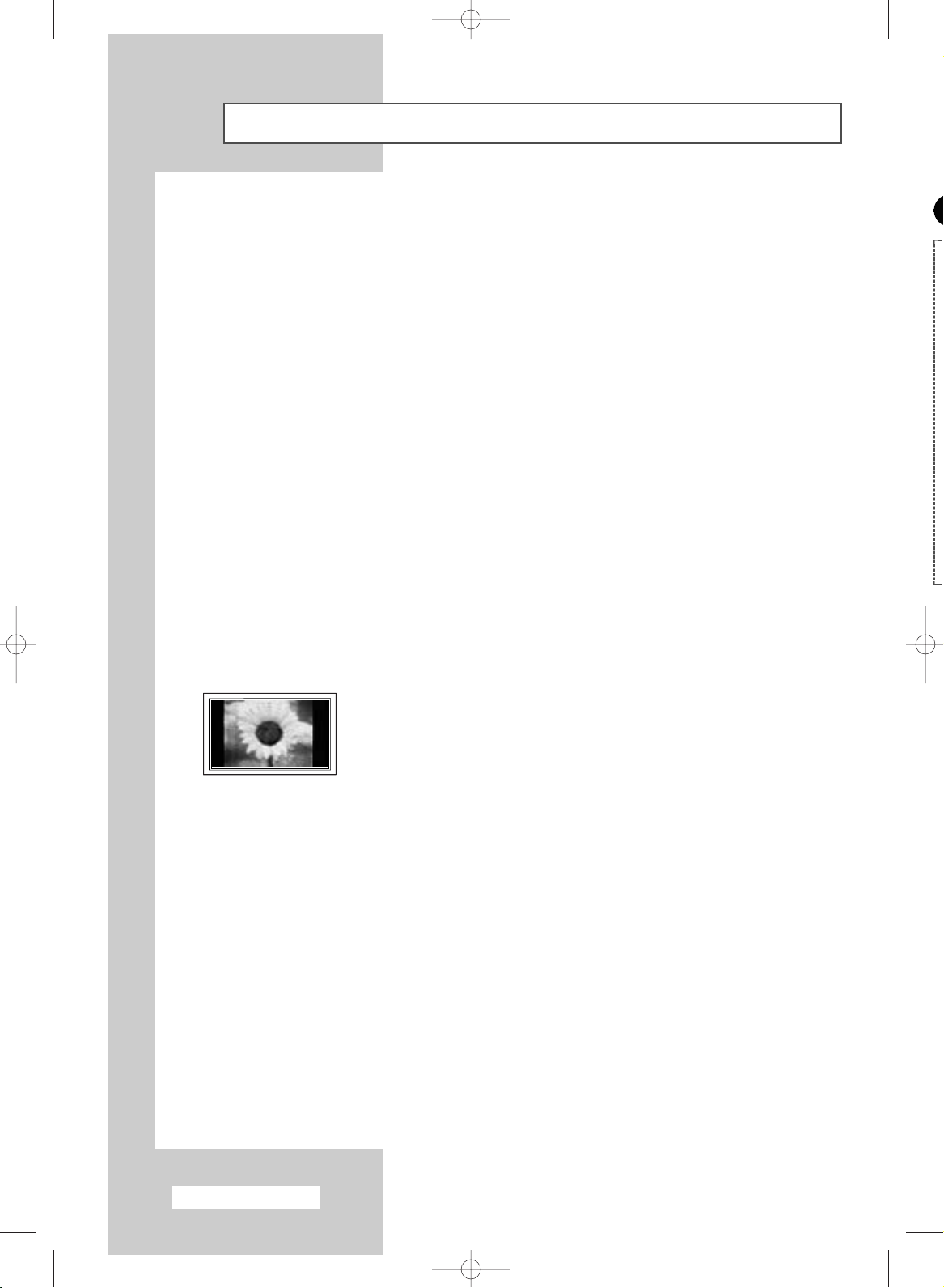
◆ A still image displayed too long may cause permanent damage to the PDP Display Panel
Watching the PDP Display in 4:3 format for a long period of time may leave
traces of borders displayed on the left, right and center of the screen caused
by the difference of light emission on the screen.
Playing a DVD or a game console may cause similar effect to the screen.
Damage caused by the above effect are not covered by the Warranty.
◆ Afterimage on the Screen.
Displaying still images from Video games and PC for longer than a certain period of time may
produce partial afterimages.
To prevent this effect, reduce the ‘brightness’ and ‘contrast’ when displaying still images for a
long time.
◆ Warranty
- Warranty does not cover any damage caused by image retention.
- Burn-in is not covered by the warranty.
◆ Installation
Be sure to contact an authorized service center, when installing your PDP Display in a location with
heavy dust, high or low temperatures, high humidity, chemical substance and where it operates
for 24 hours such as the airport, the train station or etc.
Failure to do so may cause a serious damage to your PDP Display.
Installing the product in an airtight place may shorten the lifetime of the product.
© 2007 Samsung Electronics Co., Ltd. All rights reserved.
BN68-01304A-00Eng 5/31/07 3:49 PM Page 2
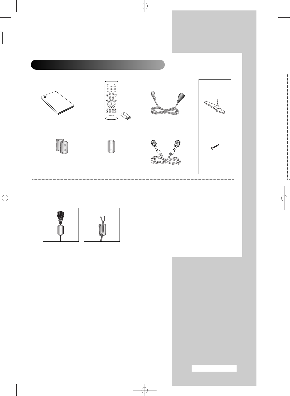
Owner’s Instructions
Remote Control/
AAA Batteries
Power Cord
PC Cable
Checking Parts
Stand-Base
(2EA)
Screws
(4EA)
Ferrite Core for
Power Cord
(3301-001110)
English - 3
Ferrite Cores for
Speaker Wire (2EA)
(Refer to page 14)
(3301-001201)
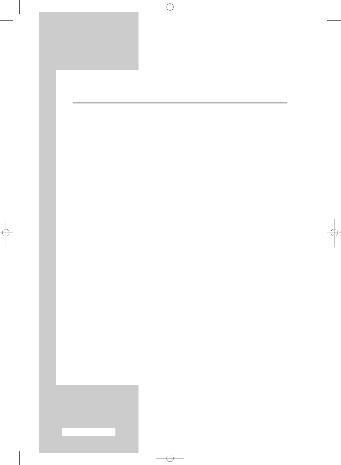
➢
Ferrite Core (Power Cord, Speaker Wire)
The ferrite cores are used to shield the cables from interference.
When connecting a cable, open the ferrite core and clip it around the cable near the plug.
BN68-01304A-01Eng 6/28/07 3:50 PM Page 3
Contents
◆ FOREWORD
■ User Instructions............................................................................................ 2
◆ CONNECTING AND PREPARING YOUR DISPLAY
■ Control Panel................................................................................................. 6
■ Infrared Remote Control ................................................................................ 8
■ Inserting the Batteries in the Remote Control................................................ 9
■ Assembling the Stand-Base .......................................................................... 9
■ Installing the Display on the Wall Attachment Panel ..................................... 10
■ Installing the Display Vertically ...................................................................... 12
■ Before Using the Video Wall and the Multiple Display Control function ........ 12
■ Connecting Speakers .................................................................................... 13
■ Switching Your PDP Display On and Off....................................................... 15
■ Choosing Your Language.............................................................................. 15
◆ USING YOUR DISPLAY
■ Changing the Picture Standard ..................................................................... 16
■ Customizing the Picture Settings................................................................... 17
■ Adjusting the RGB Color (PC Mode) ............................................................. 18
■ Setting the Picture (PC Mode)....................................................................... 18
■ Using Zoom function (PC Mode) ................................................................... 20
■ Selecting the Picture Size.............................................................................. 21
■ Freezing the Current Picture ......................................................................... 22
■ Changing the Sound Standard ...................................................................... 22
■ Customizing the Sound Settings ................................................................... 23
■ Setting the TruSurround XT........................................................................... 24
■ Activating Panel Button Lock......................................................................... 25
■ Activating Remote Control Button Lock......................................................... 26
■ Setting Up Your Personal ID Number............................................................ 27
Continued...
English - 4
BN68-01304A-00Eng 5/31/07 3:49 PM Page 4
Contents
◆ USING YOUR DISPLAY (CONTINUED)
■ Setting the MDC (Multiple Display Control) ................................................... 28
■ Preventing Screen Burn-in ............................................................................ 29
■ Reducing the Effects of Screen Burn ............................................................ 30
■ Setting the Screen Burn Protection Timer ..................................................... 31
■ Setting the Multiple Screen............................................................................ 32
■ Displaying the Setting Information................................................................. 33
■ Setting and Displaying the Current Time....................................................... 33
■ Switching the PDP Display On and Off Automatically ................................... 34
■ Selecting the Fan........................................................................................... 36
■ Viewing the Picture in Picture (PIP)............................................................... 37
■ Viewing an External Signal Source ............................................................... 38
◆ ADDITIONAL INFORMATION AND CONNECTIONS
■ Connecting to the Audio/Video Input............................................................. 39
■ Connecting to the S-Video Input.................................................................... 40
■ Connecting to the Component Input.............................................................. 40
■ Connecting to the DVD/DTV Receiver Input ................................................. 41
■ Connecting to the DVI Input .......................................................................... 41
■ Connecting to the PC Input ........................................................................... 42
■ Setting up Your PC Software (Windows only) ............................................... 43
■ Input Mode (PC/DVI) ..................................................................................... 44
■ Power Saver (PC1 mode only) ...................................................................... 45
◆ RECOMMENDATIONS FOR USE
■ Troubleshooting: Before Contacting Service Personnel................................ 46
■ Technical Specifications ................................................................................ 47
☛
➢
Press Important Note
Symbols
English - 5
BN68-01304A-00Eng 5/31/07 3:49 PM Page 5
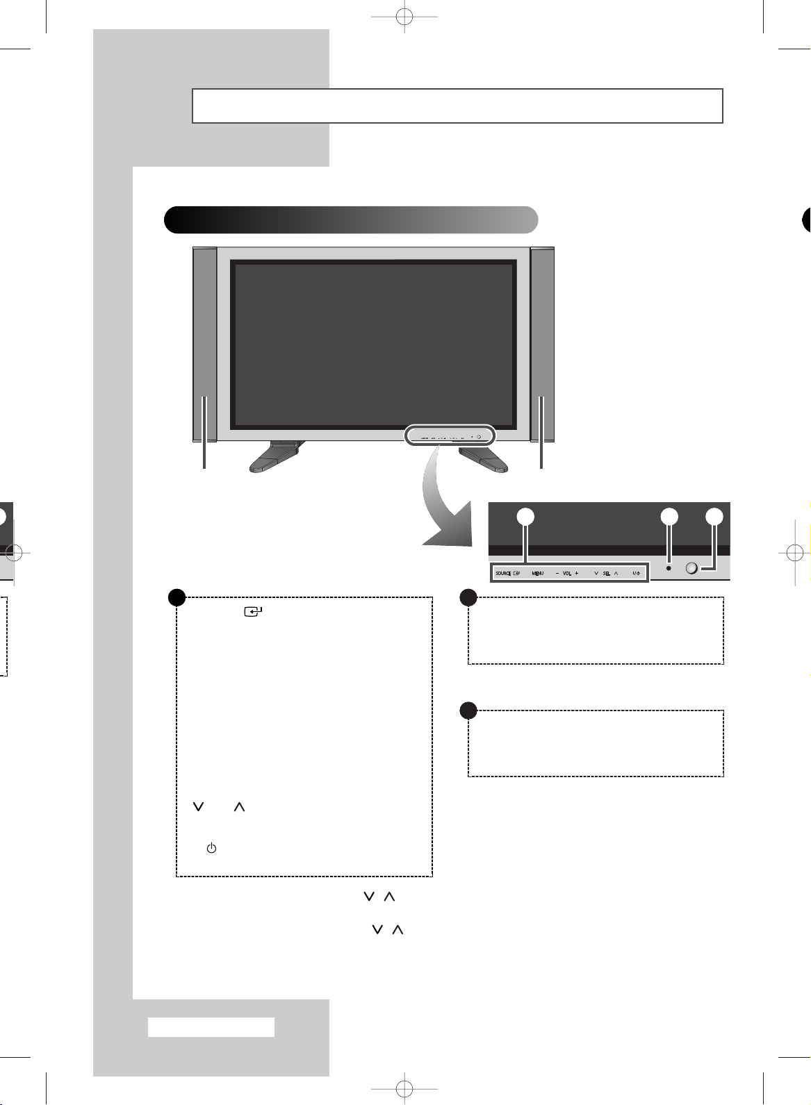
Control Panel
Front of the PDP Display
➢
The actual configuration of your PDP Display may be different,
depending on your model.
a)
b
c)
➢
d
e)
f)
➢
English - 6
➢
◆ You can use the
SEL ,
buttons to switch on the PDP Display when it is in standby
mode depending on the model.
◆ The VOL
-,+ and
SEL ,
buttons have the same function as the ▲/▼/œ/√ buttons
on the remote control.
◆ If the remote control no longer works or you have misplaced it, you can use the controls
on the panel of the PDP Display.
Continued...
➢
➢
SOURCE
- Select the external input source.
- Store your settings in the menu.
- When the Main menu is displayed on screen,
the Main menu is not operated with source key.
MENU
Display the on-screen menu.
-
VOL +
- Adjust the volume.
- Adjust an option value respectively.
(VOL + : Enter to the selected menu.)
SEL
Control the cursor in the menu.
I /
Press to turn the PDP Display on and off.
a
Power Indicator
- Power Off; Black
- Power On; Green
b
Remote Control Sensor
Aim the remote control towards this spot on the
PDP Display.
c
Speaker
(Optional)
Speaker
(Optional)
a b c
BN68-01304A-00Eng 5/31/07 3:49 PM Page 6
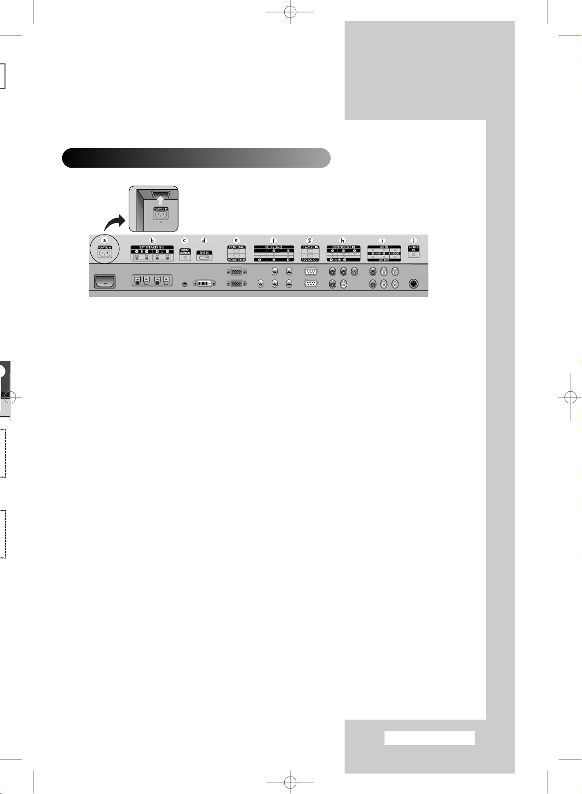
Rear Panel
a) POWER IN
Connect the supplied power cord.
b) EXT SPEAKER (8Ω)
Connect external speakers.
c) DVI/PC AUDIO IN
Connect to the audio output jack on your
PC or DVI.
➢
AUDIO is an audio input jack for PC1 and PC2
modes.
d) DVI IN
Connect to the video output jack for device with
DVI output.
e) PC IN1/PC OUT1
-
PC IN1 : Connect to the video output jack on
your PC.
-
PC OUT1 : Connect to the video input jack on
external devices.
f) PC IN2 (BNC)
Connect for RGB HV video signal input from the PC.
➢
“PC Mode” from this page onward means
PC1/PC2 mode using
RGB1(PC1) and
RGB2(PC2).
g) RS-232C
-
IN : Used for the MDC function when connecting
PC or RS-232C output of another PDP
Display.
-
OUT : Used for the MDC function when
connecting with RS-232C input of another
PDP Display.
➢
For further details about connections, refer to
Page 12.
h) COMPONENT IN
Video (Y/PB/PR) and audio (L/R) inputs for
component.
i) AV (VIDEO/AUDIO L/R)
-
IN : Video and audio inputs for external devices,
such as a camcorder or VCR.
-
OUT : Outputs for external devices.
j) S-VIDEO IN
Video input for external devices with an S-Video
output, such as a camcorder or VCR.
English - 7
➢
For further details about connection, refer to pages 39~42.
➢
Whenever you connect an audio or video system to your PDP Display, ensure that all elements are
switched off. Refer to the documentation supplied with your equipment for detailed connection
instructions and associated safety precautions.
BN68-01304A-00Eng 6/25/07 2:47 PM Page 7
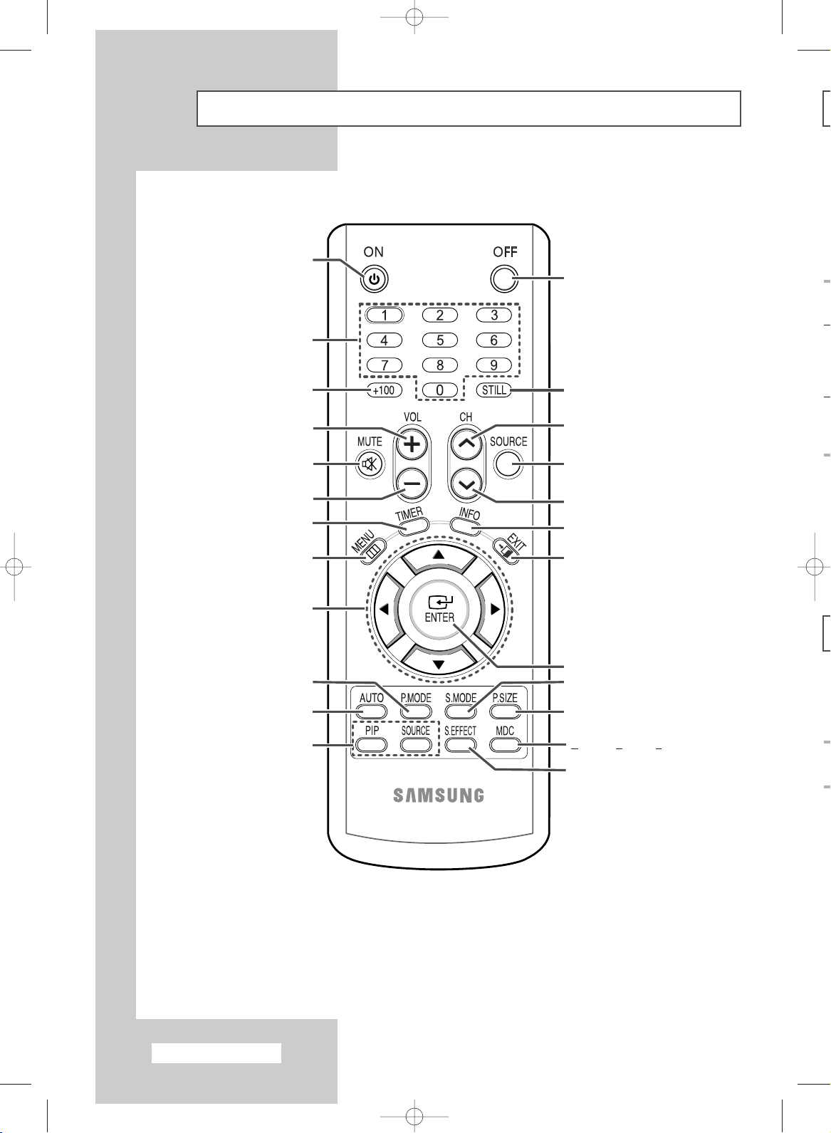
Infrared Remote Control
Y
yo
PDP DISPLAY ON
DIRECT CHANNEL SELECTION
VOLUME INCREASE
TEMPORARY SOUND SWITCH-OFF
MENU DISPLAY
MOVE TO THE REQUIRED MENU
OPTION/
ADJUST AN OPTION VALUE
RESPECTIVELY
PICTURE EFFECT SELECTION
EXTERNAL INPUT SELECTION
EXIT FROM ANY DISPLAY
PREVIOUS CHANNEL
CONFIRM YOUR CHOICE
(STORE OR ENTER)
INFORMATION DISPLAY
PIP FUNCTIONS:
- PIP ACTIVATION OR DEACTIVATION
(PIP)
- SOURCE SELECTION (SOURCE)
PICTURE SIZE
NOT AVAILABLE
SETTING THE TIMER
AUTO ADJUSTMENT IN PC MODE
PDP DISPLAY OFF
PICTURE STILL
SOUND EFFECT SELECTION
VOLUME DECREASE
NEXT CHANNEL
➢
The performance of the remote control may be affected by bright light.
➢
English - 8
SCREEN EFFECT SELECTION
(BURNING PROTECTION)
M
ULTIPLE DISPLAY CONTROL
BN68-01304A-00Eng 5/31/07 3:49 PM Page 8

You must insert or replace the batteries in the remote control when
you:
◆ Purchase the PDP Display
◆ Find that the remote control is no longer operating
correctly
1 Remove the cover on the rear of the remote control by pressing
the symbol ( ) downwards and then pulling firmly to remove it.
2 Insert two R03, UM4, “AAA” 1.5V or equivalent batteries taking
care to respect the polarities:
◆-on the battery against -on the remote control
◆+on the battery against +on the remote control
3 Replace the cover by aligning it with the base of the remote
control and pressing it back into place.
Do not mix battery types, i.e. alkaline and manganese.
Inserting the Batteries in the Remote Control
Assembling the Stand-Base
1 Assemble the PDP Display with the stand and firmly
secure the PDP Display using 4 screws provided.
➢
Two or more people should carry the PDP Display.
Never lay the PDP Display on the floor because of
possible damage to the screen.
Always store the PDP Display upright.
English - 9
BN68-01304A-00Eng 5/31/07 3:49 PM Page 9

English - 10
➢
◆
Installing the Display on the Wall Attachment Panel
Wall Bracket
Components
Plastic Hanger: 4 Screw : 11
Screw : 4
Anchor : 11
Wall Bracket Assembly
Installation Notes
◆
Contact a technician for installing the wall bracket.
◆
Samsung Electronics is not responsible for any damages to the product or harm to customers when
the installation is done by the customer.
◆
This product is for installing on cement walls. The product may not stay in place when installed on
plaster or wood.
Hinge
Accessories
➢
Refer to the correct installation guide according to your wall bracket.
1 Insert and tighten the Captive Screw in
the direction of the arrow.
When done, mount the wall bracket on
the wall.
2 Before drilling into the wall, check if the length
between the two locking holes at the back of
the product is correct.
If the length is too short or long, loosen all or
some of the 4 screws on the wall bracket to
adjust the length.
3 Check the installation diagram and mark the drill
points on the wall. Use the 5.0 mm bit to drill holes
deeper than 35 mm.
Fix each anchor in the corresponding hole.
Match each of the brackets and hinge holes to the
corresponding anchor holes and insert and tighten
the 11 screws .
Continued...
Length between the
two locking holes
Captive Screw
Wall Bracket
Hinge (Right)
There are two hinges
(left and right). Use the
correct one.
Hinge (Left)
1 Left: 1 Right: 1
◆
Only use the components and accessories shipped with the product.
BN68-01304A-00Eng 5/31/07 3:49 PM Page 10

English - 11
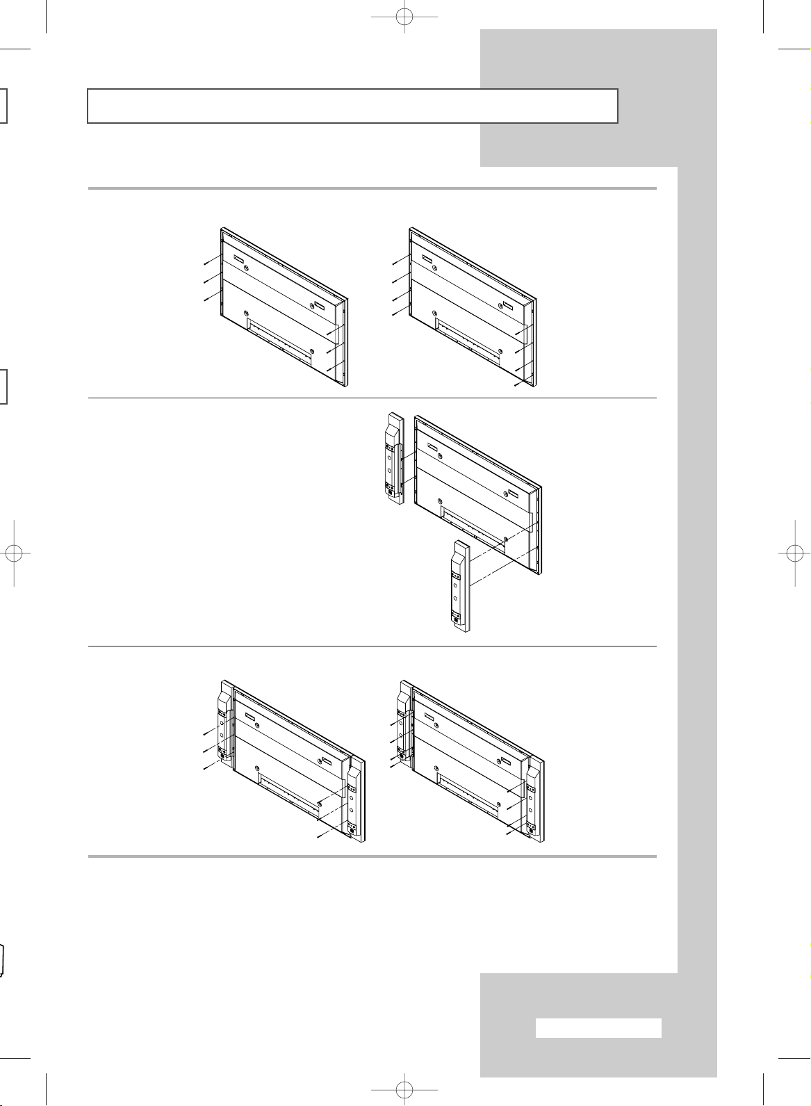
1 Remove the 4 screws on the back of the product.
3 Tighten the 4 screws in step 2 (plastic hanger
+ screw ) to the rear holes of the product.
2 Insert the screw into the plastic hanger.
(See the figure below)
☛
◆ Mount the product on the wall bracket
and make sure it is properly fixed to
the left and right plastic hangers.
◆ Be careful when installing the product
on the bracket as fingers can be
caught in the holes.
◆ Make sure the wall bracket is securely
fixed to the wall, or the product may not
stay in place after installation.
4
Remove safety pin (#) and insert the 4 product
holders into the corresponding bracket holes (
!). Then
place the product (
@) so that it is firmly fixed to the
bracket. Make sure to reinsert and tighten the safety
pin (
#) to securely hold the product to the bracket.
Wall Bracket Angle Adjustment
➢
Adjust the bracket angle to -
2obefore installing it on the wall.
◆ The shape of the product may vary depending on the model. (The assemblies of the plastic hanger
and the screw are the same)
PDP Display
Wall Bracket
Wall
1 Fix the product to the wall bracket.
2 Hold the product at the top in the center and pull it
forward (direction of the arrow) to adjust the angle.
(See the figure to the right)
3 You can adjust the bracket angle between -2° and 15°.
Make sure to use the top center,
and not the left or the right side of
the product to adjust the angle.
To mount the product on the wall bracket
BN68-01304A-00Eng 5/31/07 3:49 PM Page 11

Installing the Display Vertically
Before Using the Video Wall and the Multiple Display Control function
Example for Multiple Display Control connections
1 Please create ID for each PDP Display before
installing them close together. It may be difficult to
create IDs when operating the remote control for
PDPs that are installed close to each other.
2 For details about Video Wall configuration and
operation, refer to “Setting the Multiple Screen”
on page 32.
➢
◆ You can connect a Composite (Video) without
a distributor as you would connect a PC.
◆ Select ID input on the menu. Use the numeric
buttons to enter the ID for PDP Display
adjustment. You can operate the remote
control only for the PDP Display that has been
selected.
◆ For details about Multiple Display Control, refer
to “Setting the MDC (M
ultiple Display Control)”
on page 28.
Example for 2x2 Video Wall function
Example for 2x2 Video Wall connections
Rear of the PDP Display Rear of the PDP Display
English - 12
➢
You can install the PDP Display vertically.
In this case, the fan automatically works.
If you wish to stop the fan, position the PDP
Display horizontally and then set “
Fan” to “Off ”
in the “
Function” menu.
Please use the wall attachment panel exclusively
when installing vertically. And you have to put the
bottom of the PDP Display with menu buttons on
the left when viewed from front.
❋
Samsung shall not be liable for
damages caused by installing the
product at the different direction from
the figure below.
②
①
BN68-01304A-00Eng 6/25/07 2:47 PM Page 12
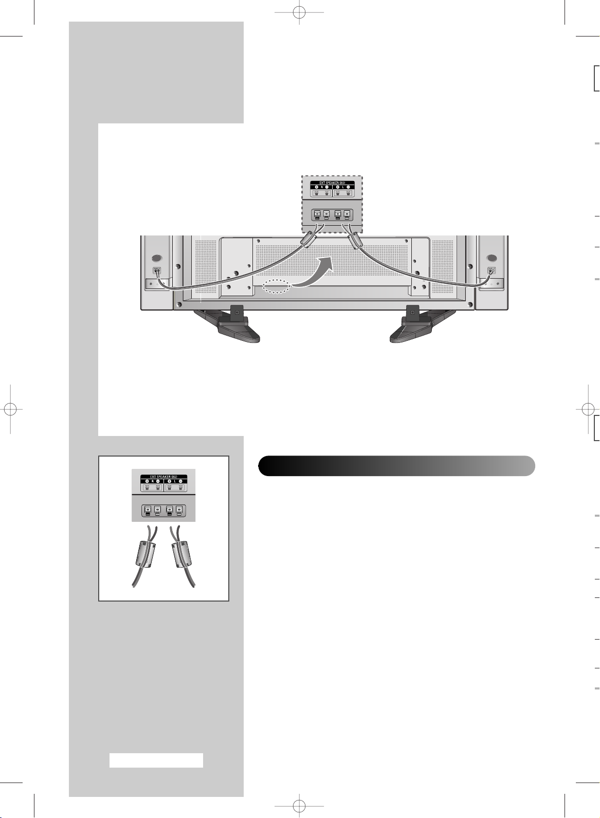
Connecting Speakers
1 Remove the screws on the rear of the PDP Display.
2 Hang the two “T” shaped hangers
on the square holes on the rear of
the PDP Display.
3 Tighten the PDP Display and the speaker bracket using the screws removed from the PDP Display.
➢
When moving your PDP Display, do NOT hold the speaker connected to your PDP Display. It may
damage the bracket clamping the speaker and your PDP Display together and result in a drop of
your PDP Display and a risk of personal damage and injury.
Continued...
PPM42M7H PPM50M7H
PPM42M7H PPM50M7H
English - 13
➢
Speakers are optional. You have to purchase the speakers
additionally.
PPM42M7H
PPM50M7H
BN68-01304A-00Eng 5/31/07 3:49 PM Page 13
W
se
in
T
Ferrite Cores
The ferrite cores are used to attenuate undesired signals.
When connecting cables, attach one of these ferrite cores to the cable
near the connector.
Connect the speaker audio cable to the external speaker output jack on the rear of the PDP Display
matching the “+” and “
-
” ends of the cable with the diagram on the PDP Display.
➢
◆ The speakers MUST have a power handling capability of 10 watts minimum (impedance 8Ω).
◆ When you connect the speaker wire to the external speaker out connector, first bind the
speaker wire round the ferrite core to secure it.
English - 14
BN68-01304A-01Eng 6/28/07 3:50 PM Page 14
When you start using your PDP Display for the first time, you must
select the language which will be used for displaying menus and
indications.
1 Press the MENU ()button.
Result
: The main menu is displayed.
2 Press the … or † button to select Setup.
Result
: The Setup menu is displayed.
3 Press the ENTER () button.
4 Press the … or † button to select Language.
Press the
ENTER () button.
Result
: The available languages are listed.
5 Select the appropriate language by pressing the … or † button.
Press the
ENTER () button.
6 Press the EXIT button to exit.
Choosing Your Language
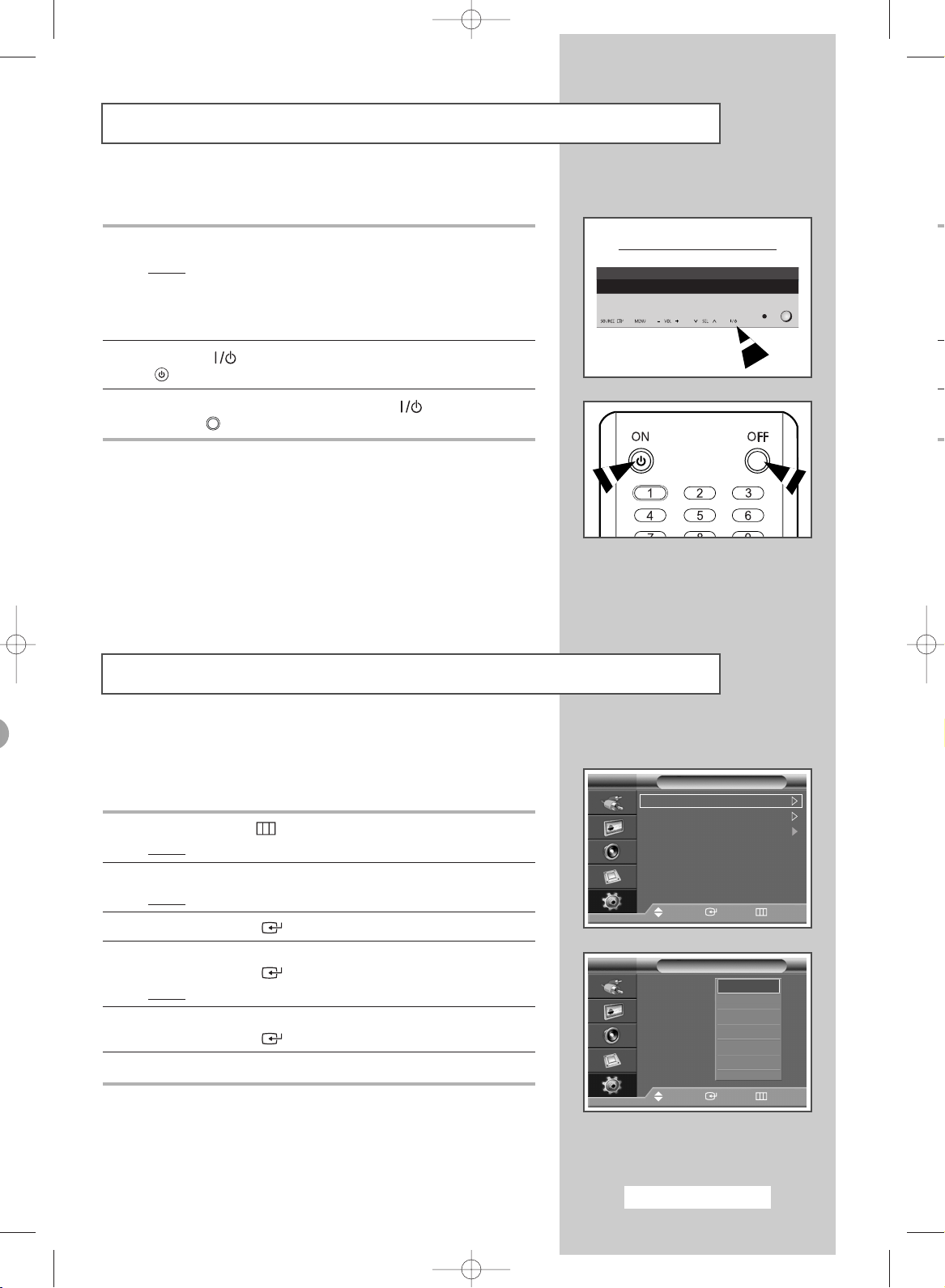
The mains lead is attached to the rear of your PDP Display.
1 Plug the mains lead into an appropriate socket.
Result
: The Standby indicator on the front of the PDP Display
lights up.
➢
The main voltage is indicated on the rear of the PDP
Display and the frequency is 50 or 60Hz.
2 Press the “ ” button on the front of the PDP Display (or the ON
() button on the remote control) to switch the PDP Display on.
3 To switch your PDP Display off, press the “ ” button again (or
the
OFF () button on the remote control).
T
Front of the PDP Display
Switching Your PDP Display On and Off
English - 15
Time
Language : English
PC
Setup
Move Enter Return
Time
Language : English
PC
Setup
Move Enter Return
English
Français
Deutsch
Italiano
Español
Português
††
BN68-01304A-00Eng 5/31/07 3:56 PM Page 15
Y
co
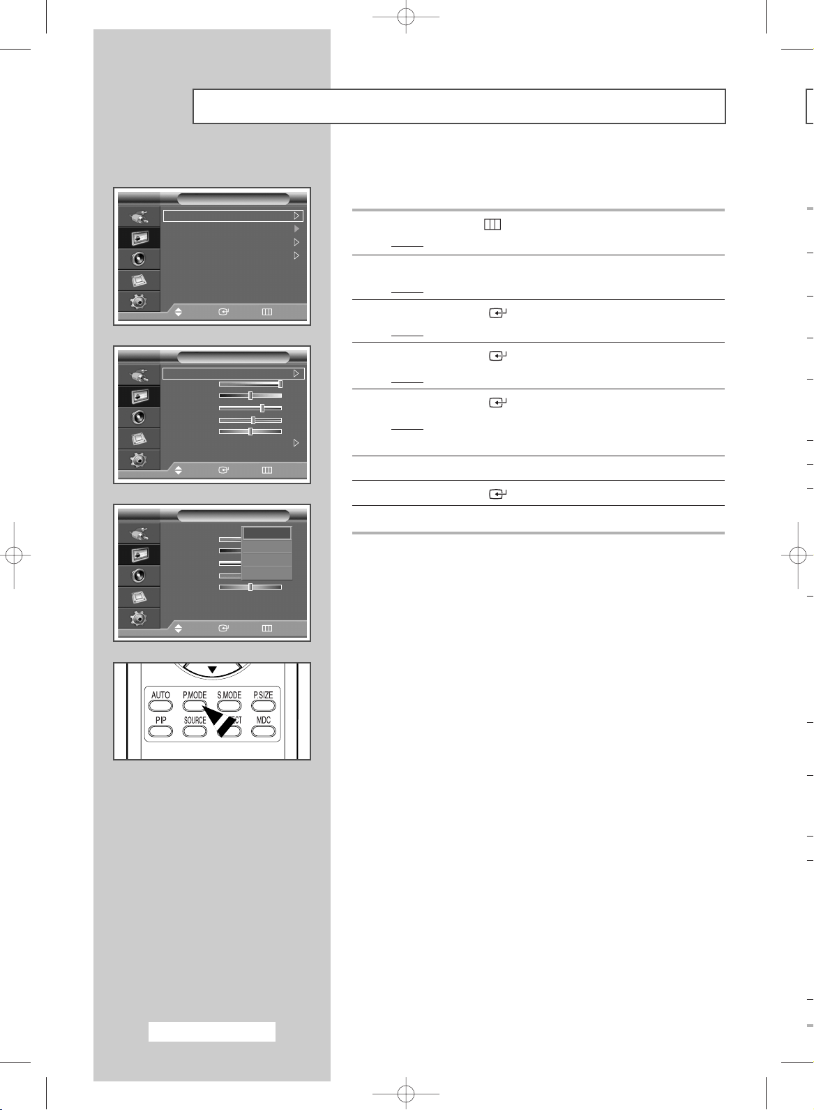
You can select the type of picture which best corresponds to your
viewing requirements.
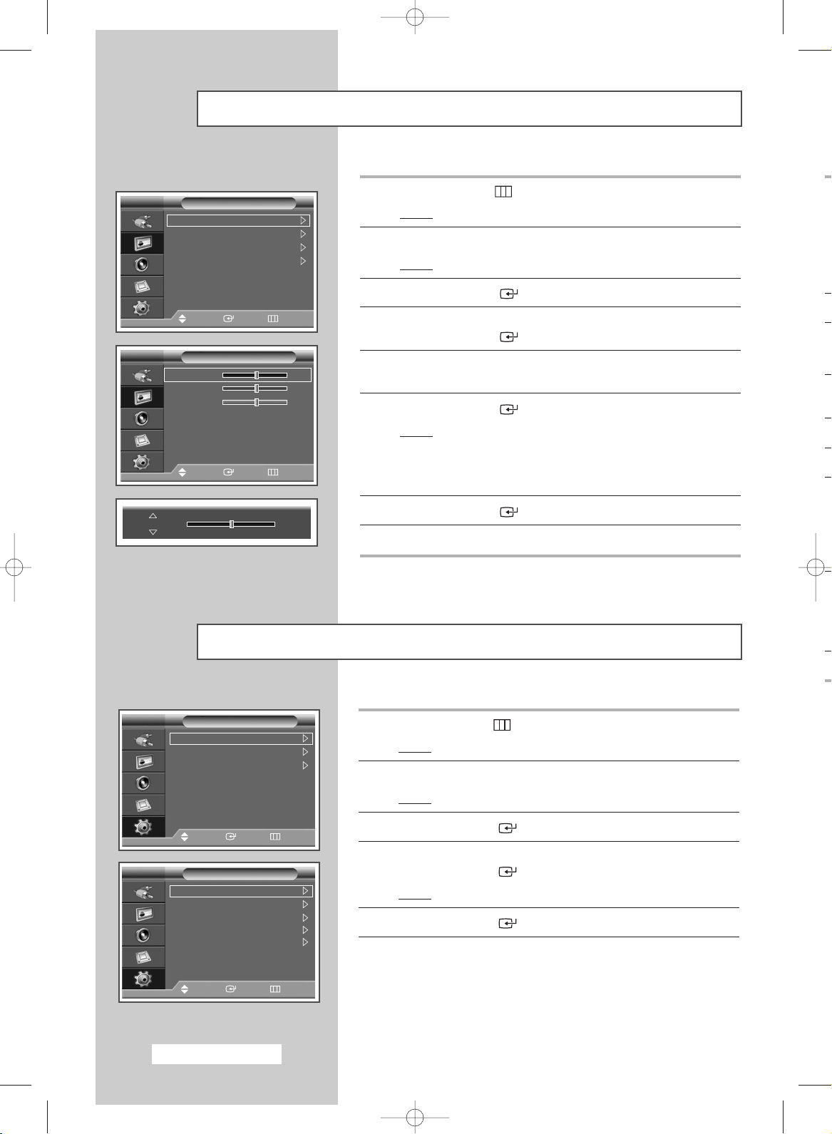
1 Press the MENU ()button.
Result
: The main menu is displayed.
2 Press the … or † button to select Picture.
Result
:
The
Picture menu is displayed.
3 Press the ENTER () button.
Result
:
The
Mode is selected.
4 Press the ENTER () button again.
Result
:
The
Mode menu is displayed.
5 Press the ENTER () button.
Result
: The following
options
are available.
Dynamic - Standard - Movie - Custom
6 Select the required option by pressing the … or † button.
7 Press the ENTER () button.
8 Press the EXIT button to exit.
➢
You can also set these options simply by pressing the
P.MODE (Picture Mode) button on the remote
control.
Changing the Picture Standard
English - 16
Mode : Dynamic
Color Control
Size : 16:9
PIP
Picture
Move Enter Return
Mode
Move Enter Return
Mode : Dynamic
Contrast 100
Brightness 50
Sharpness 75
Color 55
Tint G 50 R 50
Color Tone : Cool1
Reset
Mode
Move Enter Return
Mode : Dynamic
Contrast 100
Brightness 50
Sharpness 75
Color 55
Tint G 50 R 50
Color Tone : Cool1
Reset
Dynamic
Standard
Movie
Custom
BN68-01304A-00Eng 5/31/07 3:51 PM Page 16

Your PDP Display has several setting options that allow you to
control the picture quality.
1 Press the MENU ()button.
Result
: The main menu is displayed.
2 Press the … or † button to select Picture.
Result
:
The
Picture menu is displayed.
3 Press the ENTER () button.
Result
:
The
Mode is selected.
4 Press the ENTER () button again.
Result
:
The
Mode menu is displayed.
5 Press the ENTER () button.
Result
: The following
options
are available.
Dynamic - Standard - Movie - Custom
6 Select the required option by pressing the … or † button.
7 Press the ENTER () button.
8 Select the required option by pressing the … or † button.
Result
: The following
options
are available.
◆ Contrast - Brightness - Sharpness - Color Tint (NTSC only)
◆ Contrast - Brightness - Color : PC or DVI
Mode.
9 Press the ENTER () button.
Result
: The horizontal bar is displayed.
Press the
œ or √ button until you reach the optimal
setting.
➢
◆ Press the … or † button to select other option(s).
◆ The settings values may vary depending on the input
source. (ex. AV, Component, PC, or DVI.)
10 Press the MENU () button to return to Mode menu.
Press the
… or † button to select Color Tone.
Press the
ENTER () button.
11 Select the required option by pressing the … or † button.
Result
: The following
options
are available.
Cool2 - Cool1 - Normal - Warm1 - Warm2
12 Press the ENTER () button.
13 To return the factory defaults, select Reset by pressing the … or
† button. Press the ENTER () button.
Result
: The previously adjusted settings will be reset to the
factory defaults.
➢
The reset function is set for each mode (Dynamic,
Standard, Movie, or Custom).
➢
The reset function is also set for each Color Tone (Cool2,
Cool1, Normal, Warm1, or Warm2).
14 Press the EXIT button to exit.
Customizing the Picture Settings
English - 17
Contrast 100
Mode : Dynamic
Color Control
Size : 16:9
PIP
Picture
Move Enter Return
Mode
Move Enter Return
Mode : Dynamic
Contrast 100
Brightness 50
Sharpness 75
Color 55
Tint G 50 R 50
Color Tone : Cool1
Reset
Mode
Move Enter Return
Mode : Dynamic
Contrast 100
Brightness 50
Sharpness 75
Color 55
Tint G 50 R 50
Color Tone : Cool1
Reset
Mode
Move Enter Return
Mode : Dynamic
Contrast 100
Brightness 50
Sharpness 75
Color 55
Tint G 50 R 50
Color Tone : Cool 1
Reset
Cool2
Cool1
Normal
Warm1
Warm2
BN68-01304A-00Eng 5/31/07 3:51 PM Page 17
English - 18
Time
Language : English
PC
Setup
Move Enter Return
Image Lock
Position
Auto Adjustment
Image Reset
Zoom
PC
Move Enter Return
Adjusting the RGB Color (PC Mode)
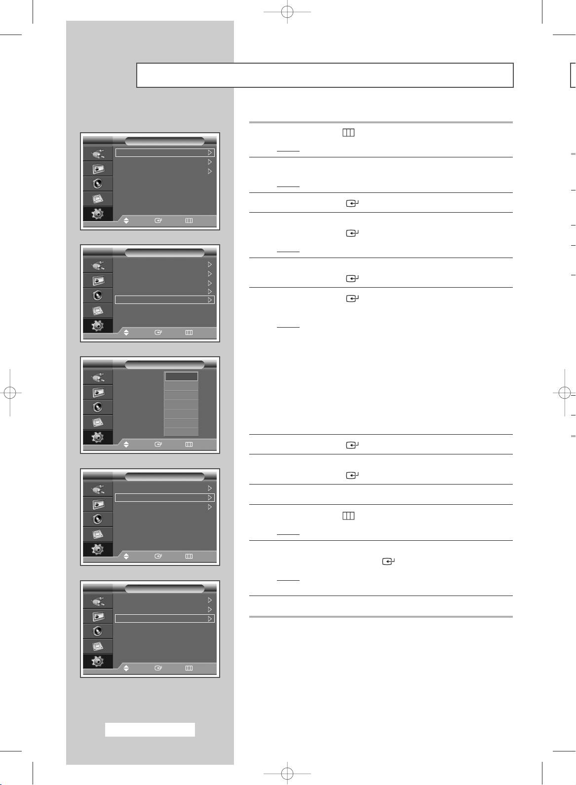
1 Press the MENU ()button.
Result
: The main menu is displayed.
2 Press the … or † button to select Picture.
Result
: The Picture menu is displayed.
3 Press the ENTER () button.
4 Press the … or † button to select Color Control.
Press the
ENTER () button.
5 Select the required option (Red, Green, or Blue) by pressing the
… or † button.
6 Press the ENTER () button.
Result
: The horizontal bar is displayed.
Press the
œ or √ button until you reach the optimal
setting.
➢
Press the … or † button to select other option(s).
7 Press the ENTER () button.
8 Press the EXIT button to exit.
➢
Preset to the PC mode by pressing the SOURCE button.
Setting the Picture (PC Mode)
1 Press the MENU ()button.
Result
: The main menu is displayed.
2 Press the … or † button to select Setup.
Result
: The
Setup menu is displayed.
3 Press the ENTER () button.
4 Press the … or † button to select PC.
Press the
ENTER () button.
Result
: The PC menu is displayed.
5 Press the ENTER () button to select Image Lock.
Continued...
➢
Preset to the PC mode by pressing the SOURCE button.
Mode : Dynamic
Color Control
Size : 16:9
PIP
Picture
Move Enter Return
Color Control
Move Enter Return
Red 50
Green 50
Blue 50
Red 50
BN68-01304A-00Eng 5/31/07 3:51 PM Page 18

English - 19
6 Press the … or † button to select the option (Coarse or Fine) to
be adjusted. Press the
ENTER () button.
Result
: The horizontal bar is displayed.
Press the
œ or √ button until you reach the optimal
setting.
➢
Press the … or † button to select other option(s).
7 Press the ENTER () button.
8 Press the MENU ()button.
Result
: The PC menu is displayed again.
9 Press the … or † button to select Position.
Press the
ENTER () button.
10 Adjust the position by pressing the …, †, œ, or √ button.
11 Press the ENTER () button.
12 Press the … or † button to select Auto Adjustment.
Press the
ENTER () button.
Result
: The screen quality and position are automatically reset.
The settings are all finished, and the PDP Display will
automatically return to the previous picture.
13 To return the factory defaults, select Image Reset by pressing
the
… or † button. Press the ENTER () button.
Result
: The previously adjusted settings will be reset to the
factory defaults.
14 Press the EXIT button to exit.
Auto Adjustment in Progress
Please wait.
Image Lock
Move Enter Return
Coarse 50
Fine 30
Position
Move Enter Return
Coarse 50
Image Reset is completed.
Return
BN68-01304A-00Eng 5/31/07 3:51 PM Page 19
a
1 Press the MENU ()button.
Result
: The main menu is displayed.
2 Press the … or † button to select Setup.
Result
: The Setup menu is displayed.
3 Press the ENTER () button.
4 Press the … or † button to select PC.
Press the
ENTER () button.
Result
: The PC menu is displayed.
5 Press the … or † button to select Zoom.
Press the
ENTER () button.
6 Press the ENTER () button again.
Select the required option by pressing the
… or † button.
Result
: The following options are available.
0 - 1 - 2 - 3 - 4 - 5 - 6
➢
◆ Option 0 represents a normal screen.
The greater the number, the more magnified the screen.
◆ You can select the position and reset functions by
selecting options 1 through 6. (If you select option 0, the
position and reset functions are not selected.)
◆ If you have selected the Zoom function as between 1~6,
you will not be able to select the Auto Adjustment function.
7 Press the ENTER () button.
8 Press the … or † button to select Position.
Press the
ENTER () button.
9 Adjust the position by pressing the …, †, œ, or √ button.
10 Press the MENU () button.
Result
: The
Zoom menu is displayed again.
11 To return the factory defaults, select Reset by pressing the … or
† button. Press the ENTER () button.
Result
: The previously adjusted settings will be reset to the
factory defaults.
12 Press the EXIT button to exit.
➢
Preset to the PC mode by pressing the SOURCE button.
English - 20
Using Zoom function (PC Mode)
Y
re
Po
Time
Language : English
PC
Setup
Move Enter Return
Image Lock
Position
Auto Adjustment
Image Reset
Zoom
PC
Move Enter Return
Zoom : 1
Position
Reset
Zoom
Move Enter Return
Zoom : 1
Position
Reset
Zoom
Move Enter Return
Zoom : 0
Position
Reset
Zoom
Move Enter Return
0
1
2
3
4
5
6
BN68-01304A-00Eng 5/31/07 3:51 PM Page 20

Selecting the Picture Size
English - 21
You can select the picture size which best corresponds to your viewing
requirements.
1 Press the MENU ()button.
Result
: The main menu is displayed.
2 Press the … or † button to select Picture.
Result
: The Picture menu is displayed.
3 Press the ENTER () button.
4 Press the … or † button to select Size.
Press the
ENTER () button.
5 Select the required option by pressing the … or † button.
Result
: The following options are available.
◆ 16:9 : Sets the picture to 16:9 wide mode.
◆ Wide 4:3 : Magnify the size of the picture more than 4:3.
Move the screen up/down using the
… or †
button after selecting the by pressing the √
or ENTER ()button.
◆ Zoom : Magnify the size of the picture vertically on
screen.
◆ 4:3 : Sets the picture to 4:3 normal mode.
6 Press the ENTER () button.
7 Press the EXIT button to exit.
➢
◆ You can select these options simply by pressing the P.SIZE
button on the remote control.
◆ If you change the picture size when PIP is On, PIP will
automatically be turned Off.
◆ Depending on the input source, the P.SIZE options may vary.
◆ PC and DVI modes, only 16:9 & 4:3 modes can be selected.
Positioning and Sizing the screen using Zoom
➢
◆ Resizing the screen using the Zoom enables the positioning
and sizing of the screen to up/down direction using the
… or
† button as well as the screen size.
◆ Move the screen up/down using the … or † button after
selecting the by pressing the
œ or √ button.
◆ Resize the screen vertically using the … or † button after
selecting the by pressing the
œ or √ button.
(Pressing the
… button extends it upward and pressing the
† button extends it downward.)
◆ Screen enlargement operates only in Video/S-Video/
Component input modes.
◆ PC/DVI modes prevent the screen enlargement function.
PC to DVI Mode
Mode : Dynamic
Color Control
Size : 16:9
PIP
Picture
Move Enter Return
16:9
Wide 4:3
Zoom
4:3
Size
Move Enter Return
16:9
Wide 4:3
Zoom
4:3
Size
Move Enter Return
BN68-01304A-00Eng 5/31/07 3:51 PM Page 21
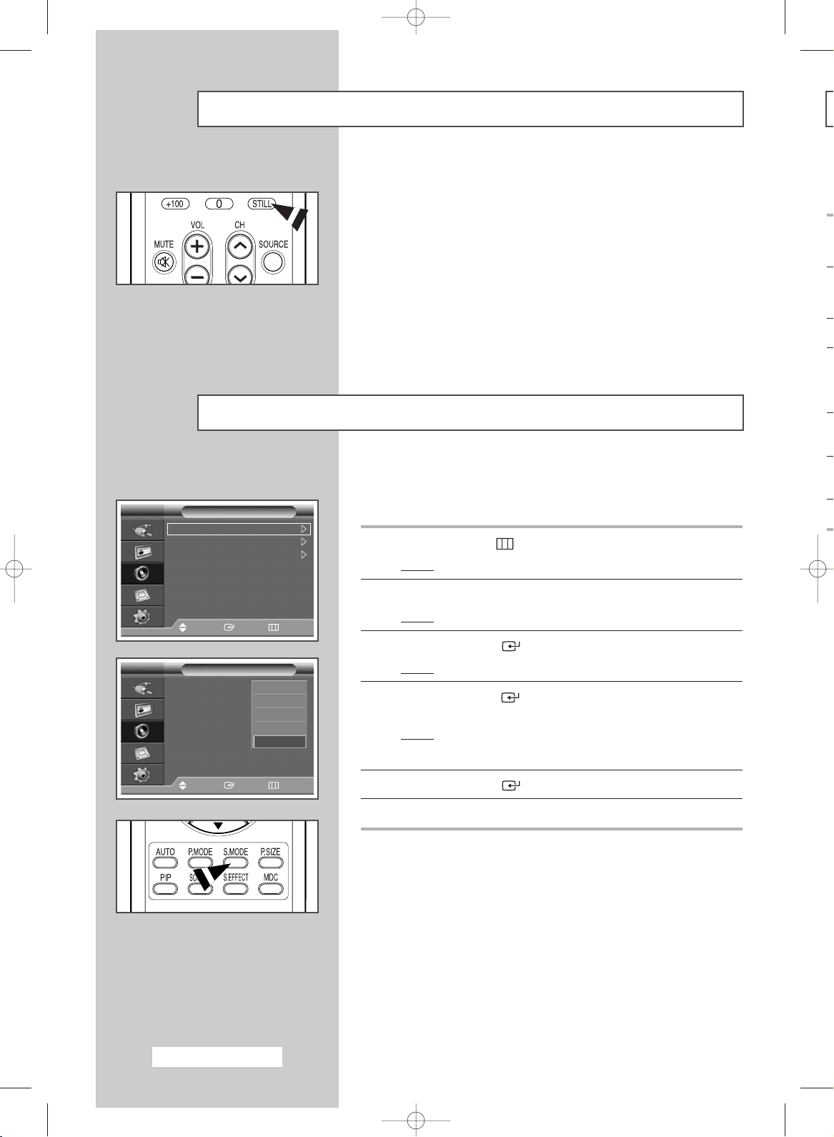
You can freeze the picture when watching a moving picture simply
by pressing the “STILL” button. To return to normal viewing, press
it again.
➢
In PIP mode, Still function will be applied to the main and
sub picture at the same time.
Freezing the Current Picture
You can select the type of special sound effect to be used when
watching a given broadcast.
1 Press the MENU ()button.
Result
: The main menu is displayed.
2 Press the ▲ or ▼ button to select Sound.
Result
: The
Sound menu is displayed.
3 Press the ENTER () button.
Result
: The Mode is selected.
4 Press the ENTER () button again.
Select the required option by pressing the
▲ or ▼ button.
Result
: The following options are available.
Standard - Music - Movie - Speech - Custom
5 Press the ENTER () button.
6 Press the EXIT button to exit.
➢
You can select these options by simply pressing the
S.MODE (Sound Mode) button on the remote control.
Changing the Sound Standard
English - 22
Y
th
Mode : Custom
Equalizer
SRS TS XT : Off
Sound
Move Enter Return
Mode : Custom
Equalizer
SRS TS XT : Off
Sound
Move Enter Return
Standard
Music
Movie
Speech
Custom
BN68-01304A-00Eng 6/25/07 11:33 AM Page 22

Customizing the Sound Settings
English - 23
Your PDP Display has several settings which allow you to control
the sound quality.
1 Press the MENU ()button.
Result
: The main menu is displayed.
2 Press the … or † button to select Sound.
Result
:
The
Sound menu is
displayed.
3 Press the ENTER () button.
4 Press the … or † button to select Equalizer.
Press the
ENTER () button.
Result
:
The
Equalizer menu is
displayed.
5 Select the required option (balance or equalizer) by pressing the
œ or √ button.
6 Press the … or † button until you reach the
optimal
setting.
Press the
ENTER () button.
7 Press the EXIT button to exit.
➢
If you make any changes to the sound settings, the sound
standard is automatically switched to
Custom.
Mode : Custom
Equalizer
SRS TS XT : Off
Sound
Move Enter Return
Equalizer
Move Adjust Return
100Hz 300Hz 1KHz 3KHz 10KHz
R
L
+
0
-
+
0
-
Balance
BN68-01304A-00Eng 6/25/07 11:33 AM Page 23

T
th
h
co
co
TruSurround XT is a patented SRS technology that solves the
problem of playing 5.1 multichannel content over two speakers.
TruSurround delivers a compelling, virtual surround sound
experience through any two-speaker playback system, including
internal PDP Display speakers. It is fully compatible with all
multichannel formats.
1 Press the MENU ()button.
Result
: The main menu is displayed.
2 Press the … or † button to select Sound.
Result
:
The
Sound menu is
displayed.
3 Press the ENTER () button.
4 Press the … or † button to select SRS TS XT.
Press the ENTER () button.
5 Select Off or On by pressing the … or † button.
Press the
ENTER () button.
6 Press the EXIT button to exit.
Setting the TruSurround XT
English - 24
Mode : Custom
Equalizer
SRS TS XT : Off
Sound
Move Enter Return
Mode : Custom
Equalizer
SRS TS XT : Off
Sound
Move Enter Return
Off
On
BN68-01304A-00Eng 6/25/07 11:33 AM Page 24

This feature allows you to lock the PDP Display panel buttons so
that it cannot be operated via the PDP Display panel. It can,
however, still be operated via the remote control. Only remote
control can release the panel lock setting, so keep the remote
control away from unauthorized users.
1 Press the MENU ()button.
Result
: The main menu is displayed.
2 Press the ▲ or ▼ button to select Function.
Result
:
The
Function
menu is
displayed.
3 Press the ENTER () button.
4 Press the ▲ or ▼ button to select Safety Lock.
Press the
ENTER () button.
5 Press the ENTER () button again to select Key Lock.
6 Select Off or On by pressing the ▲ or ▼ button.
Press the
ENTER () button.
7 Press the EXIT button to exit.
Activating Panel Button Lock
English - 25
Screen Burn Protection
Safety Lock
Multi Control
Video Wall
Fan : Off
Function
Move Enter Return
Key Lock : Off
IR Lock
Change PIN
Safety Lock
Move Enter Return
Key Lock : Off
IR Lock
Change PIN
Safety Lock
Move Enter Return
Off
On
BN68-01304A-00Eng 5/31/07 3:52 PM Page 25
English - 26
This feature allows you to lock the remote control so that it cannot
be operated via the remote control. It can, however, still be
operated via the PDP Display Panel buttons.
1 Press the MENU ()button.
Result
: The main menu is displayed.
2 Press the ▲ or ▼ button to select Function.
Result
:
The
Function
menu is
displayed.
3 Press the ENTER () button.
4 Press the ▲ or ▼ button to select Safety Lock.
Press the
ENTER () button.
5 Press the ▲ or ▼ button to select IR Lock.
Press the
ENTER () button.
6 Press the EXIT button to exit.
➢
When IR Lock is set to On, you will not be able to use the
remote control even if the remote control button is pressed.
To unlock the Remote Control Button Lock, enter the PIN
using the numeric keys on the remote control.
‘IR LOCK : OFF’ will appear. The default PIN is “0000”.
You can set the PIN in the “Change PIN” menu.
T
a
Id
IR Lock : On
Activating Remote Control Button Lock
Screen Burn Protection
Safety Lock
Multi Control
Video Wall
Fan : Off
Function
Move Enter Return
Key Lock : Off
IR Lock
Change PIN
Safety Lock
Move Enter Return
BN68-01304A-00Eng 5/31/07 3:52 PM Page 26
English - 27
This feature sets viewing restrictions and prevents unauthorized
access to your PDP Display through the PIN (Personal
Identification Number), which is a 4 digit number.
1 Press the MENU ()button.
Result
: The main menu is displayed.
2 Press the ▲ or ▼ button to select Function.
Result
:
The
Function
menu is
displayed.
3 Press the ENTER () button.
4 Press the ▲ or ▼ button to select Safety Lock.
Press the
ENTER () button.
5 Press the ▲ or ▼ button to select Change PIN.
Press the
ENTER () button.
6 Press the number buttons to enter your current 4-digit pin number.
➢
The default pin number for a new PDP Display set is “0000”.
7 Press the numeric buttons to enter your new 4-digit pin number.
Re-enter your new pin number to confirm.
8 Press the EXIT button to exit.
➢
If you forget the pin number, press the remote control
buttons in the following sequence, which resets the pin to
0-0-0-0: MUTE, 1, 8, 6.
Setting Up Your Personal ID Number
Screen Burn Protection
Safety Lock
Multi Control
Video Wall
Fan : Off
Function
Move Enter Return
Key Lock : Off
IR Lock
Change PIN
Safety Lock
Move Enter Return
Change PIN
0 .. 9: Enter PIN Return
Enter PIN
Enter New PIN
Change PIN
0 .. 9: Enter PIN Return
Enter PIN
Enter New PIN
****
BN68-01304A-00Eng 5/31/07 3:52 PM Page 27
English - 28
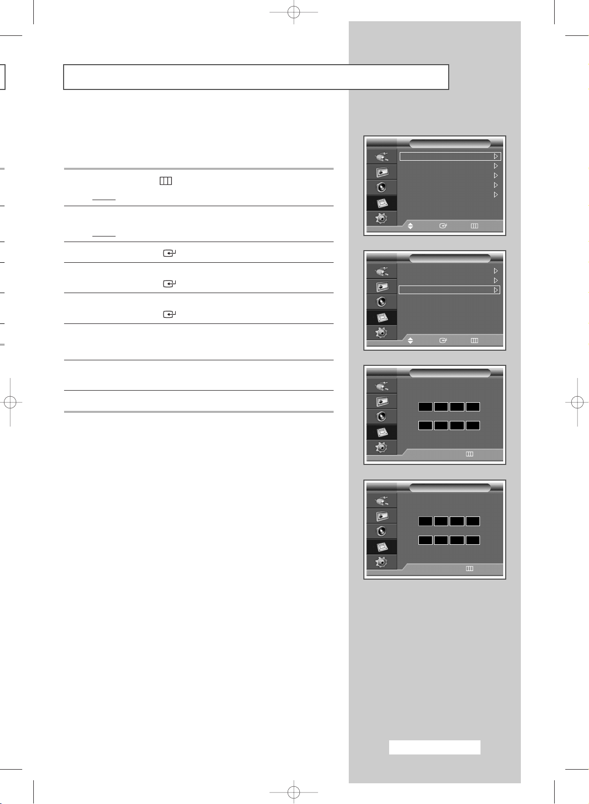
Setting the MDC (Multiple Display Control)
This function enables you to easily control the connected PDP
Displays on the PC by specifying IDs to connected PDP Displays.
1 Press the MENU ()button.
Result
: The main menu is displayed.
2 Press the ▲ or ▼ button to select Function.
Result
:
The
Function
menu is displayed.
3 Press the ENTER () button.
4 Press the ▲ or ▼ button to select Multi Control.
5 Press the ENTER () button.
Result
: The Multi Control menu is displayed with t
he
ID
Setup
selected.
6 Press the ENTER () button again.
Select the ID setup number by using the numeric buttons.
Press the
ENTER () button.
7 Press the ▲ or ▼ button to select ID Input.
Press the
ENTER () button.
8 Enter ID input number by using the numeric buttons.
9 Press the EXIT button to exit.
➢
To operate the multi control function, PDP1 and PDP2
should be set in the ID Setup mode. When entering the ID
Input number of PDP1 while the PDP Display is set in the
ID Input mode, only PDP1 is switched to the Menu screen
and you can operate the remote control. At this time, PDP2
doesn't operate with the remote control and displays the
standby mode of ID Input.
➢
For further details, refer to the MDC program guide.
➢
You can select these options by simply pressing the MDC
(Multiple Display Control) button on the remote control.
➢
Refer to the following Web site for information about MDC
programs and protocol documents:
http://www.samsung.com/support/productsupport/downloa
d/index.aspx
T
sc
se
(H
b
Screen Burn Protection
Safety Lock
Multi Control
Video Wall
Fan : Off
Function
Move Enter Return
ID Setup : 00
ID Input :
--
Multi Control
Move Enter Return
ID Setup :
ID Input :
--
Multi Control
Move Enter Return
00
ID Setup : 00
ID Input :
--
Multi Control
0 .. 9: Enter ID Input Number
BN68-01304A-00Eng 5/31/07 3:52 PM Page 28
English - 29
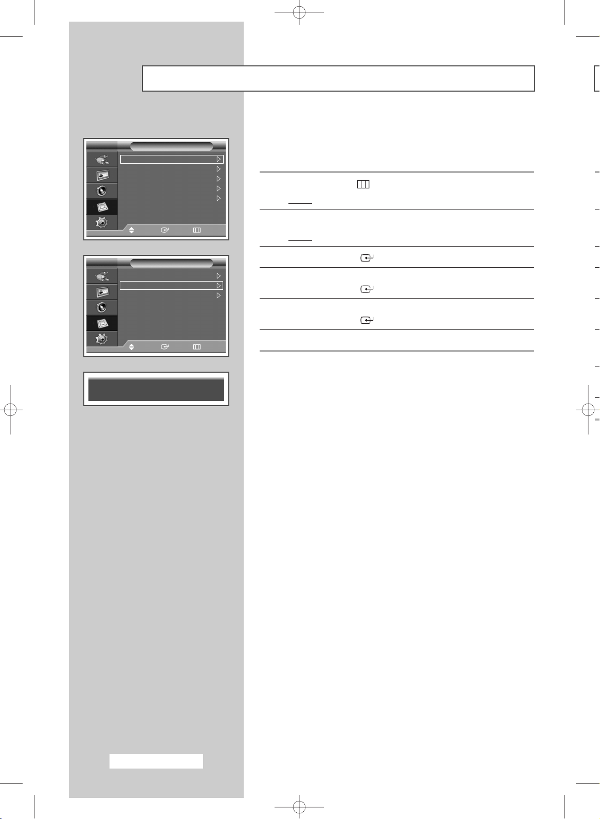
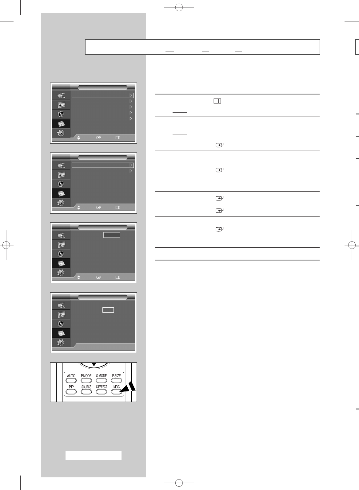
Preventing Screen Burn-in
To reduce the possibility of screen burn, this unit is equipped with
screen burn prevention technology. This technology enables you to
set picture movement up/down (Vertical Line) and side to side
(Horizontal Dot). The Time setting allows you to program the time
between movement of the picture in minutes.
1 Press the MENU ()button.
Result
: The main menu is displayed.
2 Press the … or † button to select Function.
Result
: The
Function menu is displayed.
3 Press the ENTER () button.
4 Press the … or † button to select Screen Burn Protection.
Press the
ENTER () button.
Result
: The Screen Burn Protection menu is displayed
with the
Pixel Shift selected.
5 Press the ENTER () button again.
Result
: The Pixel Shift menu is selected.
➢
You can select these options by simply pressing the
S.EFFECT button on the remote control.
6 Press the ENTER () button.
Select
On by pressing the … or † button for making the screen
move per regular hour and preventing the residual image.
Press the
ENTER () button.
➢
Pixel Shift: Using this function, you can minutely move
pixels on the PDP in horizontal or vertical direction to
prevent after image on the screen.
7 Select the required option (Horizontal Dot, Vertical Line, or
Time) by pressing the … or † button.
Press the
ENTER () button.
8 Press the … or † button until you reach the optimal setting.
Press the ENTER () button.
➢
Optimum condition for pixel shift;
9 Press the EXIT button to exit.
Screen Burn Protection
Safety Lock
Multi Control
Video Wall
Fan : Off
Function
Move Enter Return
Pixel Shift
All White
Signal Pattern
Inverse
Bar
Bar & Inverse
Timer
Screen Burn Protection
Move Enter Return
Pixel Shift : Off
Horizontal Dot : 4
Vertical Line : 4
Time : 4 min.
Pixel Shift
Move Enter Return
Off
On
Pixel Shift : On
Horizontal Dot : 4
Vertical Line : 4
Time : 4 min.
Pixel Shift
Move Enter Return
Horizontal Dot
Vertical Line
Time
PPM42M7H
2
4
4 min.
PPM50M7H
4
4
4 min.
BN68-01304A-00Eng 5/31/07 3:52 PM Page 29
English - 30
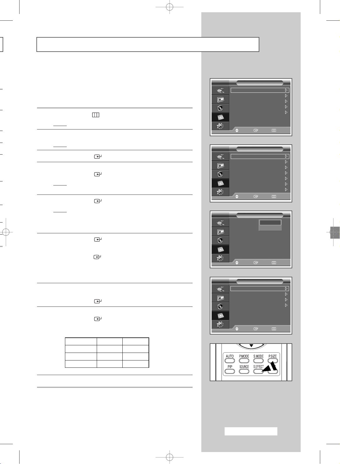
Reducing the Effects of Screen Burn
If screen burn has occurred, you can select a white screen or
inverse function to help remove screen burn artifacts.
1 Press the MENU ()button.
Result
: The main menu is displayed.
2 Press the … or † button to select Function.
Result
: The Function menu is displayed.
3 Press the ENTER () button.
4 Press the … or † button to select Screen Burn Protection.
Press the
ENTER () button.
Result
: The Screen Burn Protection menu is displayed
with the
Pixel Shift selected.
5 Press the … or † button to select the option (All White, Signal
Pattern
, Inverse, Bar or Bar & Inverse). Press the ENTER
() button.
➢
All White: This function removes after images on the
screen by changing the color of pixels to white. Use this
function when there are remaining after images or symbols
on the screen especially when you displayed a still image
on the screen for a long time.
➢
Signal Pattern:
This function removes after images on
the screen by moving all the pixels on the PDP Display
according to a pattern. Use this function when there are
remaining after images or symbols on the screen especially
when you displayed a still image on the screen for a long time.
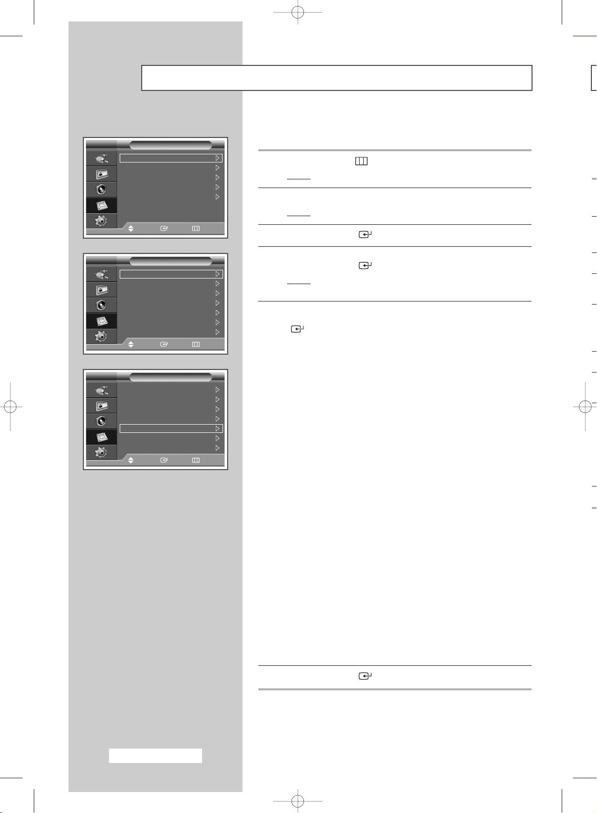
➢
Inverse: This function removes after images on the screen
when the PDP Display is remained on for proloned periods
by converting RGB input signal into GBR. Compared to All
White and Signal Pattern function, this function can reduce
burn in when you watch PDP Display. Using the inverse
function when you watch PDP Display can cause the color
reversal on the screen. (ex. The colors in red line can be
shown as the colors in green line on the screen.)
➢
Bar:
This function removes after images on the screen when the
PDP Display is remained on for proloned periods by crossing the
vertical white bar from left to right. Compared to All White and
Signal Pattern function, this function can reduce burn in when
you watch PDP Display. Using the bar mode function when you
watch PDP Display can cause poor picture quality with the
vertical white bar appeared on some parts of the screen.
➢
Bar & Inverse:
This function removes after images on the
screen when the PDP Display is remained on for proloned
periods by converting RGB input signal into GBR and crossing
the vertical white bar from left to right. Compared to All White and
Signal Pattern function, this function can reduce burn in when
you watch PDP Display. Using the inverse function when you
watch PDP Display can cause the color reversal on the screen.
(ex. The colors in red line can be shown as the colors in green
line on the screen.)
6 Press the ENTER () button.
➢
To remove after images on the screen, use either All White,
Signal Pattern, Inverse, Bar or Bar & Inverse function.
Although both of the four functions remove after images on the
screen, “
Signal Pattern” is more effective.
➢
The after image removal function has to be executed for a long
time (approximately 1 hour) to effectively remove after images on
the screen. If after image is not removed after the execution of the
function, repeat the function additionally.
Y
If
w
fi
Screen Burn Protection
Safety Lock
Multi Control
Video Wall
Fan : Off
Function
Move Enter Return
Pixel Shift
All White
Signal Pattern
Inverse
Bar
Bar & Inverse
Timer
Screen Burn Protection
Move Enter Return
Pixel Shift
All White
Signal Pattern
Inverse
Bar
Bar & Inverse
Timer
Screen Burn Protection
Move Enter Return
BN68-01304A-00Eng 5/31/07 3:52 PM Page 30
 Loading...