

Samsung PNM-9084QZ User Manual

NETWORK CAMERA
User Manual
PNM-9084QZ

Network Camera
User Manual
Copyright
Hanwha Techwin
©2019
Trademark
Each of trademarks herein is registered. The name of this product and other trademarks mentioned in this manual are the registered trademark of their
respective company.
Restriction
Copyright of this document is reserved. Under no circumstances, this document shall be reproduced, distributed or changed, partially or wholly, without
formal authorization.
Disclaimer
Hanwha Techwin
provided. Use of this document and the subsequent results shall be entirely on the user’s own responsibility.
right to change the contents of this document without prior notice.
Design and specications are subject to change without prior notice.
The initial administrator ID is “admin” and the password should be set when logging in for the rst time.
Please change your password every three months to safely protect personal information and to prevent the damage of the information
theft.
Please, take note that it’s a user’s responsibility for the security and any other problems caused by mismanaging a password.
makes the best to verify the integrity and correctness of the contents in this document, but no formal guarantee shall be
Co., Ltd. All r ights reser ved.
Hanwha Techwin
reserves the
overview
IMPORTANT SAFETY INSTRUCTIONS
1. Read these instructions.
2. Keep these instructions.
3. Heed all warnings.
4. Follow all instructions.
5. Do not use this apparatus near water.
6. Clean the contaminated area on the product surface with a soft, dry cloth or a damp cloth.
(Do not use a detergent or cosmetic products that contain alcohol, solvents or surfactants or oil constituents
as they may deform or cause damage to the product.)
7. Do not block any ventilation openings, Install in accordance with the manufacturer’s instructions.
8. Do not install near any heat sources such as radiators, heat registers, stoves, or other apparatus (including
amplifiers) that produce heat.
9. Do not defeat the safety purpose of the polarized or grounding-type plug. A polarized plug has two blades
with one wider than the other. A grounding type plug has two blades and a third grounding prong. The wide
blade or the third prong are provided for your safety. If the provided plug does not fit into your outlet, consult
an electrician for replacement of the obsolete outlet.
10. Protect the power cord from being walked on or pinched particularly at plugs, convenience receptacles, and
the point where they exit from the apparatus.
11. Only use attachments/ accessories specified by the manufacturer.
12. Use only with the cart, stand, tripod, bracket, or table specified by the manufacturer,
or sold with the apparatus. When a cart is used, use caution when moving the cart/
apparatus combination to avoid injury from tip-over.
13. Unplug this apparatus during lighting storms or when unused for long periods of time.
14. Refer all servicing to qualified service personnel. Servicing is required when the apparatus
has been damaged in any way, such as power-supply cord or plug is damaged, liquid has
been spilled or objects have fallen into the apparatus, the apparatus has been exposed to rain or moisture,
does not operate normally, or has been dropped.
15. This product is intended to be supplied by a Listed Power Supply Unit marked “Class 2” or “LPS” and rated
from PoE(42-57 Vdc), 0.8 A.
16. This product is intended to be supplied by isolation power.
17. If you use excessive force when installing the product, the camera may be damaged and malfunction.
If you forcibly install the product using non-compliant tools, the product may be damaged.
18. Do not install the product in a place where chemical substances or oil mist exists or may be generated. As
edible oils such as soybean oil may damage or warp the product, do not install the product in the kitchen or
near the kitchen table.
This may cause damage to the product.
19. When installing the product, be careful not to allow the surface of the product to be stained with chemical
substance.
Some chemical solvents such as cleaner or adhesives may cause serious damage to the product’s surface.
20. If you install/disassemble the product in a manner that has not been recommended, the production functions/
performance may not be guaranteed.
Install the product by referring to “Installation & connection” in the user manual.
21. Installing or using the product in water can cause serious damage to the product.
WARNING
TO REDUCE THE RISK OF FIRE OR ELECTRIC SHOCK, DO NOT EXPOSE THIS PRODUCT
TO RAIN OR MOISTURE. DO NOT INSERT ANY METALLIC OBJECT THROUGH THE
VENTILATION GRILLS OR OTHER OPENNINGS ON THE EQUIPMENT.
Apparatus shall not be exposed to dripping or splashing and that no objects filled with liquids,
such as vases, shall be placed on the apparatus.
To prevent injury, this apparatus must be securely attached to the Wall/ceiling in accordance
with the installation instructions.
CAUTION
CAUTION
RISK OF ELECTRIC SHOCK.
DO NOT OPEN
CAUTION
: TO REDUCE THE RISK OF ELECTRIC SHOCK.
DO NOT REMOVE COVER (OR BACK).
NO USER SERVICEABLE PARTS INSIDE.
REFER SERVICING TO QUALIFIED SERVICE PERSONNEL.
EXPLANATION OF GRAPHICAL SYMBOLS
The lightning flash with arrowhead symbol, within an equilateral triangle, is
intended to alert the user to the presence of “dangerous voltage” within the
product’s enclosure that may be of sufficient magnitude to constitute a risk of
electric shock to persons.
The exclamation point within an equilateral triangle is intended to alert the user to
the presence of important operating and maintenance (servicing) instructions in
the literature accompanying the product.
●● OVERVIEW
English _3

overview
Class construction
An apparatus with CLASS construction shall be connected to a MAINS socket outlet with a
protective earthing connection.
Battery
Batteries(battery pack or batteries installed) shall not be exposed to excessive heat such as
sunshine, fire or the like.
Disconnection Device
Disconnect the main plug from the apparatus, if it’s defected. And please call a repair man in
your location.
When used outside of the U.S., it may be used HAR code with fittings of an approved
agency is employed.
CAUTION
RISK OF EXPLOSION IF BATTERY IS REPLACED BY AN INCORRECT TYPE.
DISPOSE OF USED BATTERIES ACCORDING TO THE INSTRUCTIONS.
ATTENTION
IL Y A RISQUE D’EXPLOSION SI LA BATTERIE EST REMPLACÉE PAR UNE BATTERIE DE
TYPE INCORRECT.
METTRE AU REBUT LES BATTERIES USAGÉES CONFORMÉMENT AUX INSTRUCTIONS.
These servicing instructions are for use by qualified service personnel only.
To reduce the risk of electric shock do not perform any servicing other than that contained in
the operating instructions unless you are qualified to do so.
Please use the input power with just one camera and other devices must not be connected.
The ITE is to be connected only to PoE networks without routing to the outside plant.
The wired LAN hub providing power over the Ethernet (PoE) in accordance with IEEE
802-3af shall be a UL Listed device with the output evaluated as a Limited Power Source
as defined in UL60950-1.
Unit is intended for installation in a Network Environment 0 as defined in IEC TR 62102.
As such, associated Ethernet wiring shall be limited to inside the building.
Please read the following recommended safety precautions carefully.
yDo not place this apparatus on an uneven surface.
yDo not install on a surface where it is exposed to direct sunlight, near heating equipment or
heavy cold area.
yDo not place this apparatus near conductive material.
yDo not attempt to service this apparatus yourself.
yDo not place a glass of water on the product.
yDo not install near any magnetic sources.
yDo not block any ventilation openings.
yDo not place heavy items on the product.
yPlease wear protective gloves when installing/removing the camera.
The high temperature of the product surface may cause a burn.
yDo not adjust or move the lens directly with your hands. Doing so could damage the lens or
degrade its performance.
yThe life expectancy of driving the lens motor is 200 rotations.
User’s Manual is a guidance book for how to use the products.
The meaning of the symbols are shown below.
yReference : In case of providing information for helping of product’s usages
yNotice : If there’s any possibility to occur any damages for the goods and human caused by
not following the instruction
Please read this manual for the safety before using of goods and keep it in the safe place.
4_ overview

CONTENTS
OVERVIEW
3
INSTALLATION & CONNECTION
10
NETWORK CONNECTION AND
SETUP
19
3 Important Safety Instructions
6 Product Features
6 Recommended PC Specifications
6 Recommended Micro SD/SDHC/SDXC
Memory Card Specifications
7 What’s Included
8 Optional Accessories for Installation
8 At a Glance
10 Installation
16 Connecting with other Device
19 Connecting the Camera Directly to Local
Area Networking
19 Connecting the Camera Directly to a DHCP
Based DSL/Cable Modem
20 Using Device Manager
20 Automatically searching camera
20 Configuring IP address
21 Manually registering camera
21 Automatically configuring IP
22 Port Range Forward (Port Mapping) Setup
23 Connecting to the Camera from a Shared
Local PC
23 Connecting to the Camera from a Remote
PC via the Internet
WEB VIEWER
24
APPENDIX
26
24 Connecting to the Camera
25 Password setting
25 Login
25 Camera Web Viewer Setup
26 Specification
28 Product Overview
29 Troubleshooting
30 Open Source Announcement
●● OVERVIEW
English _5

overview
PRODUCT FEATURES
• 4-way Camera
Each of the four camera lenses monitors a different direction.
• Dustproof/Waterproof
The dust-resistant/water-resistant design protects the product from rain and dust when installed outdoors.
(IP66)
• Multi-Streaming
This network camera can display videos in different resolutions and qualities simultaneously using different
CODECs.
• Web Browser-based Monitoring
Using the Internet web browser to display the image in a local network environment.
• Alarm
When an event occurs, related images are sent to the user’s registered e-mail and FTP server, stored on the micro
SD memory card, or signaled to the alarm output terminal.
• Tampering Detection
Detects tempering attempts on video monitoring.
• Defocus detection function
Detects the defocus phenomenon of the camera lens.
• Motion Detection
Detects motion from the camera’s video input.
• Fog detection
Detects fog that is heavier than the detection level.
• Face Detection
Detects faces in the specified area from the camera’s video input.
• IVA (Intelligent Video Analysis) function
Detects a motion or situation that meets the configured event rules.
• ONVIF Compliance
This product supports ONVIF Profile S/T.
For more information, refer to www.onvif.org.
RECOMMENDED PC SPECIFICATIONS
• CPU : Intel(R) Core(TM) i7 3.4 GHz or higher
• RAM : 8G or higher
• Supported OS : Windows 7, 8.1, 10, Mac OS X 10.13
• Recommended browser : Google Chrome
• Supported browsers : MS Explore11, MS Edge, Mozilla Firefox(Window 64bit only), Apple Safari(Mac OS X only)
• VGA : PCIe 256MB GDDR3 video graphics card or higher
Please see the appendix for detailed information on verified OS and browsers.
Some functions may be restricted even in supported browsers.
RECOMMENDED MICRO SD/SDHC/SDXC MEMORY CARD SPECIFICATIONS
• Recommended capacity : 16GB ~ 256GB(MLC type)
• Recommended Manufacturers : SanDisk, Transcend
• Product Type : High endurance
• The compatibility varies depending on the card manufacturers and types.
• It is recommended to use a memory card of 16GB or more that conforms to the UHS-3 class (MLC type)
specification.
6_ overview
WHAT’S INCLUDED
Please check if your camera and accessories are all included in the product package.
(As for each sales country, accessories are not the same.)
Appearance Item Name Quantity Description
Camera 1
Appearance Item Name Quantity Description
Cable bush 2 Spare bushes for Lan cables or alarm & audio cables.
ON
DATA
DATA PWR
OUT
IN
DATA PWR
DATA
ON
OUT
IN
HPoE injector 1
Connects power supply and network
●● OVERVIEW
Quick Guide
(Optional)
Warranty card
(Optional)
1
1
Template 1 Product installation guide
Used for assembling the dome case when installing
Machine Screws 4
the product on the pipe, wall mount, etc. or blocking a
hole.
Cap Installer 1 Used to connect the RJ45 cable.
Drill bit 1
Used for dome cover disassembly,
assembly and camera installation.
Audio/alarm cable 1 Used to connect with the audio and alarm port
English _7
overview
OPTIONAL ACCESSORIES FOR INSTALLATION
You can purchase appropriate optional accessories available.
Product type Wall mount
Model Name SBP-300WMW1
Product type Hanging mount Ceiling mount
Model Name SBP-276HMW SBP-300CMW
Product type Corner mount Pole mount
Model Name SBP-300KMW SBP-300PMW
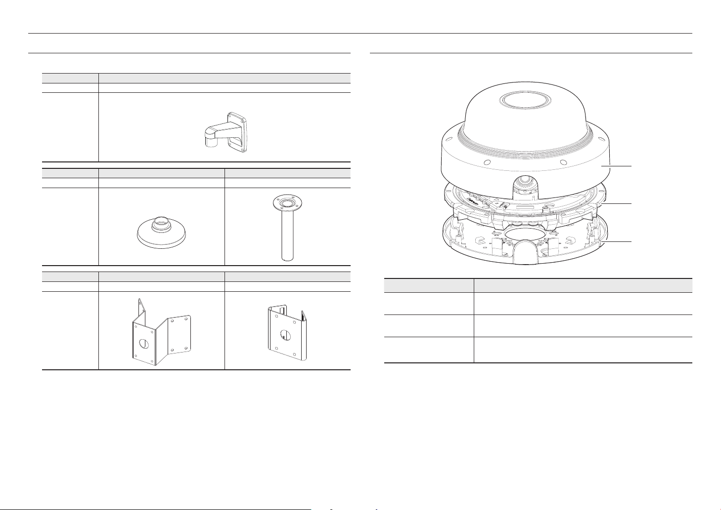
AT A GLANCE
Appearance
Dome cover
a
Camera body
b
a
b
c
Item Description
Case cover used to protect the lens and the main unit.
Body part where the camera lens and connection terminals are included.
8_ overview
c
Mount plate
Plate that fixes the camera when mounting it to the ceiling or attaching it to a separately
sold mount.
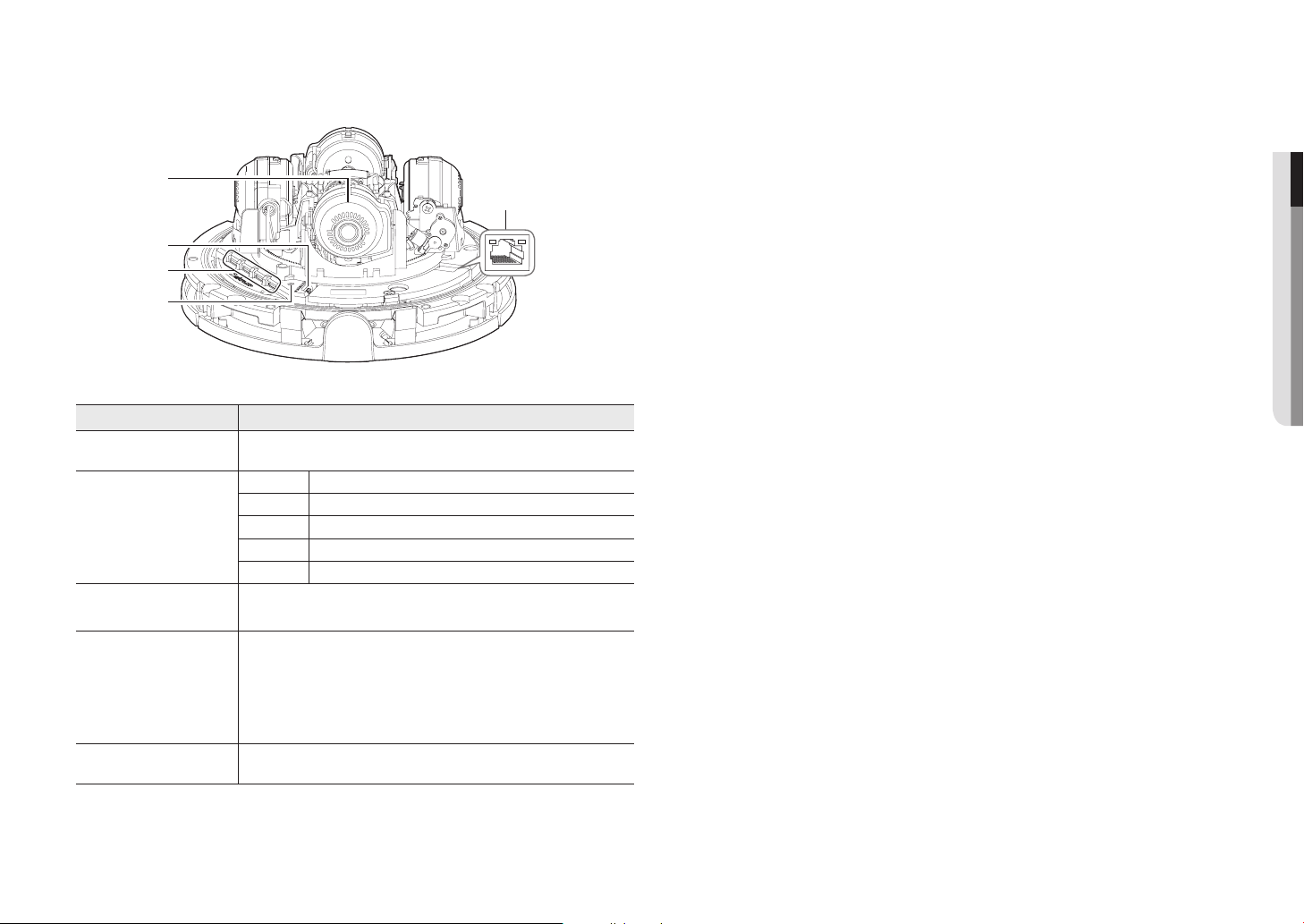
Components
a
b
c
d
Item Description
Lens
a
Audio and alarm cable port
b
Micro SD Memory Card
c
Compartment
Reset Button
d
e
CH1
CH2
CH3
RESET
CH4
4 camera lenses show different directions.
ARM-IN Used to connect the alarm input sensor or external day/night sensor.
ARM-OUT Used to connect the alarm output signal.
GND These are common ports to connect alarm input/output signals.
MIC Used to connect to a microphone.
SPEAKER Used to connect to speakers.
Compartment for the Micro SD memory card.
The button restores all camera settings to the factory default.
Press and hold for about 5 seconds to reboot the system.
If you reset the camera, the network settings will be adjusted so that DHCP can be
J
enabled. If there is no DHCP server in the network, you must run the Device Manager
program to change the basic network settings such as IP address, Subnet mask,
Gateway, etc., before you can connect to the network.
HPoE
●● OVERVIEW
HPoE Connection port
e
Terminal that connects power and network through an HPoE injector.
English _9
installation & connection
CH4
RESET
RESET
HPoE
INSTALLATION
This camera is waterproof and in compliance with the IP66 spec, but the jack connected to the external cable is not. You are
`
J
recommended to install this product below the edge of eaves to prevent the cable from being externally exposed.
Precautions before installation
Ensure you read out the following instructions before installing the camera:
• Select an installation site that can hold at least 5 times the camera’s weight.
• Stuck-in or peeled-off cables can cause damage to the product or a fire.
• For safety purposes, keep anyone else away from the installation site.
And put aside personal belongings from the site, just in case.
• If the product is installed with excessive force, it may cause damage to the camera due to malfunction.
Forcing assembly using non-compliant tools may damage the product.
Disassembling
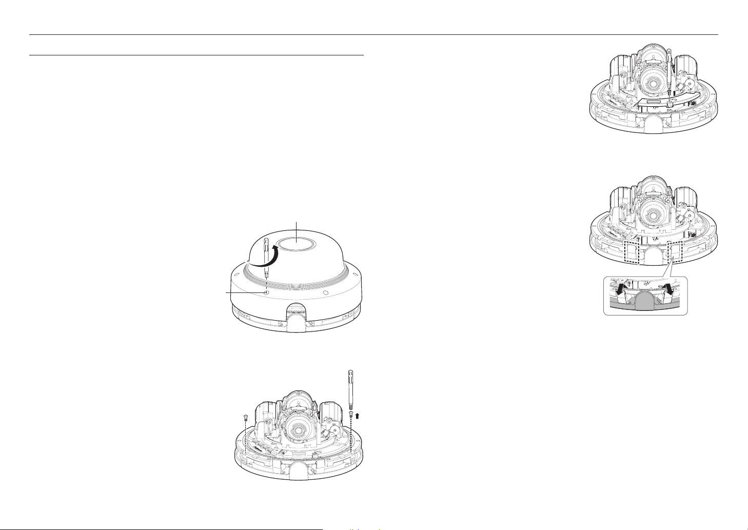
1. Remove the dome cover by loosening the
fastening bolt of the dome cover. This can be
done by turning it counterclockwise using the
drill bit provided.
Fastening bolt
Dome cover
CH1
CH2
CH3
RESET
CH4
3. Loosen and remove the screws from the cable cover.
CH1
CH2
CH3
RESET
CH4
HPoE
4. Remove the camera body and mounting plate by pulling the
plate spring, as shown in the figure.
CH1
CH2
CH3
RESET
CH4
HPoE
HPoE
2. Loosen the fastening screw on the camera body.
`
J
10_ installation & connection
Do not adjust or move the lens directly with your hands. Doing so
could damage the lens or degrade its performance.
CH1
CH2
CH3
RESET
CH4
HPoE
Inserting a Micro SD Memory Card
1. Remove the dome cover of the camera.
2. Insert a Micro SD card in the arrow direction shown in the figure.
Removing a Micro SD Memory Card
Gently press down on the exposed end of the memory card as shown in the diagram to eject the memory
card from the slot.
●● INSTALLATION & CONNECTION
CH1
CH2
CH3
RESET
CH4
Disconnect the power cable from the camera before inserting the Micro SD memory card.
`
J
Do not forcefully insert it in the reverse direction. It might damage your Micro SD memory card and your product.
`
When it rains or the humidity is high, insertion or ejection of a Micro SD card is not recommended.
`
Disassembly of the product cover should be finished within 5 minutes, or there will be the risk of internal dew condensation.
`
HPoE
CH1
CH2
CH3
RESET
CH4
You should save an SD card for each channel.
`
J
Please note that if you firmly push and release the Micro SD memory card when it is ejected, it may pop out.
`
Before removing the Micro SD memory card, in <Setup ( )>-<Event>-<Storage>, set the device to <Off> and press
`
HPoE
the [Apply] button and turn the camera off.
If you turn off the camera or remove the Micro SD memory card that contains data from the product, the data may be lost or
`
damaged.
English _11
installation & connection
Installation (mount plate)
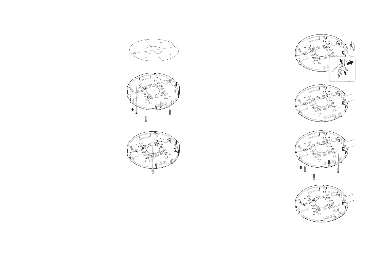
[Directly installing on ceiling]
1-1. Attach the installation template on the desired surface and drill
holes for screws and cables.
1-2. Fix the mount plate using appropriate screws.
1-3. Pull out necessary cables among LAN / audio & alarm cables
through the hole in the mount plate.
[Installing using pipe]
2-1. Attach the installation template and drill holes for screws and cables.
2-2. Separate the pipe cover of the mount plate by pressing its
sides.
2-3. Place the pipe on the mount plate.
2-4. Fix the mount plate using appropriate screws.
12_ installation & connection
2-5. Pull out necessary cables among LAN / audio & alarm
cables through the pipe.
[Attaching to the unbundled adapter]
CH4
RESET
Choose and purchase a necessary one of the following options (unbundled) that is suitable to the installation
site or for your convenience.
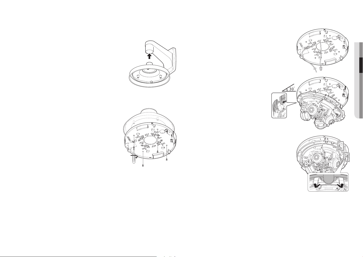
Installation (camera body and dome cover)
1. Connect the safety cable.
3-1. Install the hanging mount to the wall mount adapter.
Wall mount adapters and hanging mounts are sold separately.
`
3-2. Connect the mounting plate and the hanging mount.
2. Mount the camera body to the mount plate.
Mount it to fit the hinges as shown in the image.
`
3. Connect the terminal inside camera with the
required cable.
4. Push the leaf spring until it clicks into place as shown in the figure.
●● INSTALLATION & CONNECTION
English _13
 Loading...