

Page 1

Latest Firmware:
Please check Samsung.com for
latest update!
■ Firmware for SX1 Model
- Version : 1016.3
- Folder Name: T-TDT5AUSC
- Related Models:
PDP: C500, C530, C540, C550, C590
- Description:
This firmware will prevent below
problems:
. Picture Noise on specific channels
. Distorted picture on 70Hz, 75 Hz
Service Bulletins:
HELP : 1-888-751-4086 (Tech Support)
1-866-894-0637 (FE)
GSPN
http://gspn3.samsungcsportal.com
PLUS ONE
http://my.plus1solutions.net/clientPortals/samsung
HOT TIPS
-Power On Problems: (pg. 3)
-Video Problems: (pg. 4)
PN63C540G3FXZA
Part No
Parts Description
Location
BN40-00163A
TUNER;DTVS20CVL081A,NTSC,191CH,45.75MHZ,
TU902,CIS3
BN44-00332A
DC VSS-PDP TV;PZ-6,AC/DC,AC100~240V,50/6
P001A
BN59-00996A
REMOCON;TM1050,SAMSUNG,20PIN SINGLE,48KE
T0074
BN61-05596A
HOLDER-WIRE CABLE;LED TV,LDPE,T0.8,L150,
BN61-06108A
GUIDE-STAND NECK;58PC550,PC,CLEAR,TR-302
GSN01
BN61-06109A
GUIDE-STAND;58PC550,PC,G/F 20%,V2,BK0007
T0920
BN63-01798B
CLOTH-CLEAN;CLOTH,180,200,SEA BLUE,TOC
M9889
BN63-06476A
COVER-BOTTOM;58PC550,HIPS,V0,V1,BLK(BK-5
T0531
BN96-12678A
ASSY PDP MODULE P;S63FH-YB05,PL63FF010A,
U001A
BN96-12689A
ASSY PDP P-X MAIN BOARD;S63-FH-YB05,PL63
UX03A
BN96-12690A
ASSY PDP P-X BUFFER UPPER BOARD;S63-FH-Y
UX02A
BN96-12691A
ASSY PDP P-X BUFFER LOWER BOARD;S63-FH-Y
UX01A
BN96-12692A
ASSY PDP P-Y MAIN BOARD;S63-FH-YB05,PL63
UY04A
BN96-12693A
ASSY PDP P-Y BUFFER UPPER BOARD;S63-FH-Y
UY03A
BN96-12694A
ASSY PDP P-Y BUFFER LOWER BOARD;S63-FH-Y
UY02A
BN96-12695A
ASSY PDP P-LOGIC MAIN BOARD;S63-FH-YB05,
UL01A
BN96-12696A
ASSY PDP P-E-BUFFER BOARD;S63-FH-YB05,PL
UE01A
BN96-12697A
ASSY PDP P-F-BUFFER BOARD;S63-FH-YB05,PL
UF01A
BN96-12698A
ASSY PDP P-G-BUFFER BOARD;S63-FH-YB05,PL
UG02A
BN96-12833B
ASSY SPEAKER P;8OHM,4PIN,15W,L:670 R:107
SP01A
BN96-12991C
ASSY COVER P-FRONT;PC550 63,PMMA(CLEAR)+
F001A
BN96-13007B
ASSY COVER P-REAR;PC550 63,PCM,T0.45,BKN
R001A
BN96-13325D
ASSY CABLE P;PS63C590,FFC CABLE,0.5MM PI
FL06
BN96-13388D
ASSY BOARD P-TOUCH FUNCTION&IR;PN63C550,
FB21A
BN96-13496F
ASSY STAND P-BASE;PC550 58,GLASS,T8.0,2C
SB04A
BN96-13635A
ASSY STAND P-GUIDE NECK;58PC550,PC,CLEAR
M0029
BN96-14078A
ASSY HOLDER P-WALL;58PC550,ABS HB,BLK(BK
BN96-15071A
ASSY PCB P-MAIN;BN94-03262Z,PN63C540G3FX
M0014
Y Buffer
Y Main
SMPS
Fast Track Troubleshooting Manual, Rev. 1/11/12
X Buffer
X Main
Logic
Main
Buffer G Buffer F Buffer E Spkr Spkr
Bulletin #: ASC20110621003
Description: 2010 PDP Option Byte Table.
Please check GSPN for parts update!
Page 2
PN63C540G3FXZA
Fast Track Troubleshooting Manual
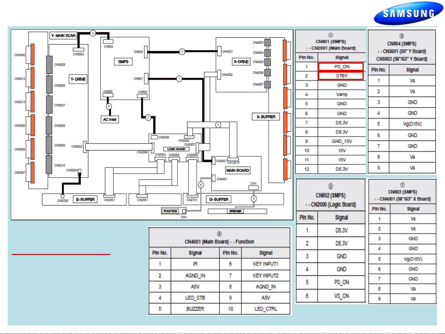
Power On Sequence:
1. STBY 5V (CN801, #2, 5v)
2. PS_ON (CN801, #1, 3.3v-0v)
3. VS_ ON (CN802, #6, 0-3.3v)
4. Panel should illuminate briefly
Page 3

PN63C540G3FXZA
Fast Track Troubleshooting Manual
Power Supply Trouble Shooting Notes:
2010/2011 models
Will not be run with the “X” or “Y” main disconnected. The SMPS will
shut down immediately. However if a meter is first connected to the
test point when power is applied it will read the correct voltage briefly
before shut- ting down.(You have enough time to check key
voltages)
CAUTION: Do not reconnect any connectors to SMPS or Y/X Boards
until power has been turned off long enough for Vs to drop below 10V
or damage will occur to X or Y Boards.
SMPS Over Current Protection
If a short circuit occurs on either the VS or VA voltage lines, the SMPS
stops operating, but should not fail. When the short circuit is removed
from the source line, the Power Supply will operate normally again.
Many SMPS Supplies are replaced needlessly!
Sample
“VITAL SIGNS”
When troubleshooting, It’s very important to first check Vs, Va, Vsc & Ve
If Vs is missing (0V), disconnect power and check for short. Use ohm
meter to measure resistance while disconnecting Y-Board & X-Board
supply feeds one at a time.
Turn Power On and Test SMPS with shorted connector removed for
correct Vs voltage verification. (It may only come up briefly but to full
level). Be careful not to reconnect power connectors until Vs falls below
10V.
If Va is low or missing, disconnect power connectors to Address Boards
and Check to see if SMPS Supply is restored. (Note Va feed normally
passes through the Y-Drive to the Address Boards (Logic Buffer Boards).
If Vsc is low or missing and Vs is OK, the failure is with the Y-Board
.
since the Y-Board generates the Vsc voltage from the supplied Vs.
If Ve is low or missing and Vs is OK, the failure is with the X-Board since the
Ve is generated by the X-Board from the supplied Vs. (Please note: In some
rare cases the Ve is generated by the Y-Board fed to the X-Board.)
Other SMPS Voltages:
Check Low Voltage feeds to the Main Board and other supplied Assemblies.
3
Page 4

PN63C540G3FXZA
Fast Track Troubleshooting Manual
TROUBLESHOOTING VIDEO PROBLEMS
1. Verify Video Operation
a) Customer Picture Test (if available)
b) “Display” (If display is OK source is suspected)
c) Substitute with known good Source
(external DVD or Signal Generator)
3. Determine cause
a) If Logic pattern is NG; Logic
board, Logic buffers or Panel
are suspect.
b) If FBE patterns is NG and Logic
is OK; Main or LVDS cable are
suspect.
c) If both are OK it is likely a
source issue.
2. Use Test Patterns in Service Mode
- ENTERING SERVICE MODE -
Customer Remote Service Remote
1. Power off 1. Power On
2. Mute, 182, Power 2. Info, Factory
4
Page 5

PN63C540G3FXZA
ALIGNMENTS:
1. Check/Adj. VS, VA, VE, & VSC according to Panel Label
and Diffusion test. (see bulletins for any special notes
before making changes)
2. Check/Set Option Bytes:
- ENTER SERVICE MODE -
a) Customer Remote: Power off; Mute, 182, Power On
b) Service Remote: Power On; Info, Factory
Fast Track Troubleshooting Manual
DIFFUSION TEST/ADJ. (cell miss-firing, older units):
• Allow the unit to warm up 15 to 20 minutes
• Access the Burn Protect Sig. Pattern in Cust. Menu.
• Adjust the Vs volts until screen errors are gone in
both dark and bright areas.
• Adjust the Vs volts within +/- 10V on the panel label.
SPECIAL NOTES:
See bulletin “Red Dots” for correction/adjustments for
this model.
5
 Loading...