

Page 1
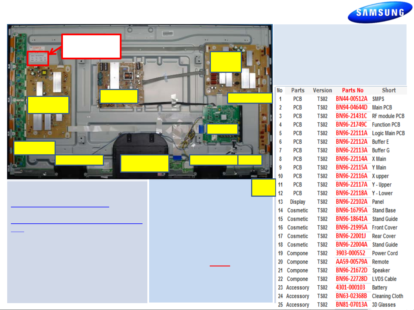
PN60E550D1FXZA
Fast Track Troubleshooting Manual – Rev 6/13/12
Vs Va Vsc Ve
Label Voltages
SMPS
Y-MAIN
Y-Buffer
Speaker L Speaker R
HELP : 888-751-4086; 866-894-0637 FE)
GSPN
http://gspn3.samsungcsportal.com
PLUS ONE
http://my.plus1solutions.net/clientPortals/sam
sung
HOT TIPS
-New 2012 Model… always check for latest
bulletins and firmware updates.
-New combined Logic/Logic Buffer Board.
-New Pentile Panel (60 inch only)
LOGIC/Buffer
BOARD
FIRMWARE
6/8/12 T-MST10PAUSC
6/2/12 T-MST10PAUSC Version 1013.3
resolves compatibility with DLNA
devices.
Avail on GSPN or Samsung,Com
X-
MAIN
MAIN
X-Buffer
Wi-Fi
Jog
Func.
Always check for latest updates
SERVICE BULLETINS
-6/6/12 ASC20120606001: Improve Eco
Sensor, replace Function Board & Upgrade
Firmware
-5/16/12 ASC20120515001: How to send
TV’s emergency data WD & AR data to SEA
- Quick Parts: Verify before Ordering
1
Page 2
PN60E550D1FXZA
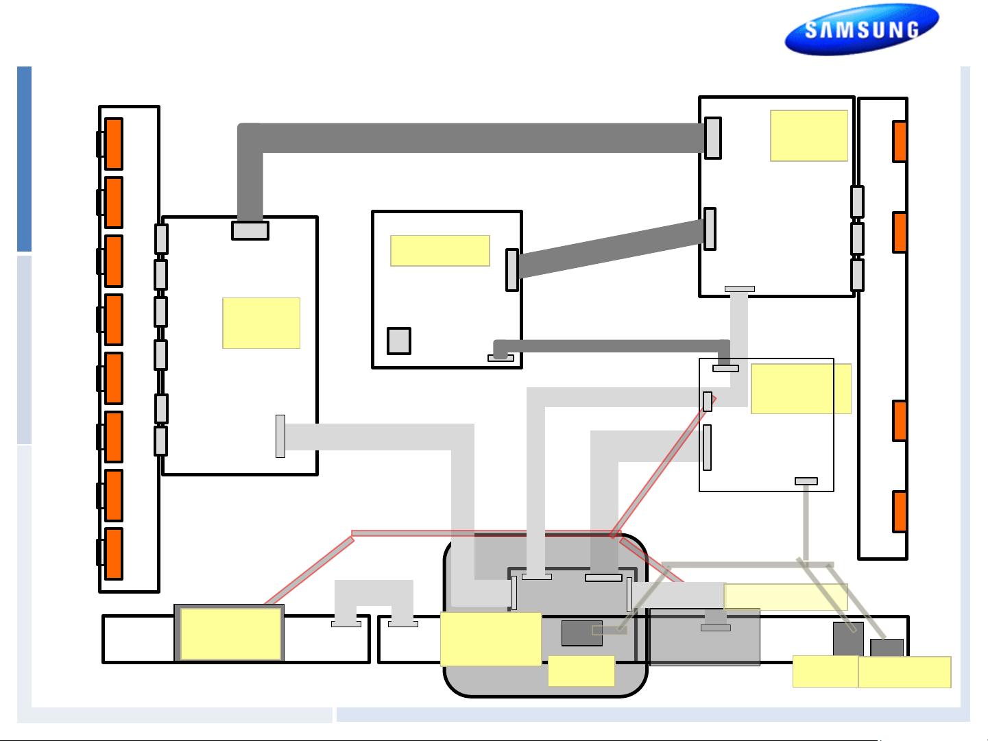
Logic/Buffer Board combined & located
Fast Track Troubleshooting Manual
CN5413
CN5414
CN5415
CN5416
CN5513
CN5514
CN5515
partially behind Stand.
CN5007
CN5000
CN5005
CN5003
CN5006
CN5004
CN5002
Y –
DRIVE
CN5001
CN800S
SMPS
CN804
CN801
CN4003
CN201
CN302
CN4005
CN4004
CN1602
X –
DRIVE
CN4000
CN4001
CN4002
MAIN
BOARD
CN1201
U2
CN4408
CN4407
CN4404
CN4403
CN5516
Speaker
(R)
CN2505
CN2004
CN2000
LOGIC
BOARD
CN2003
CN2000
B/T
CN2005
Speaker (L)
CN2704
Wi-fi
function
Page 3
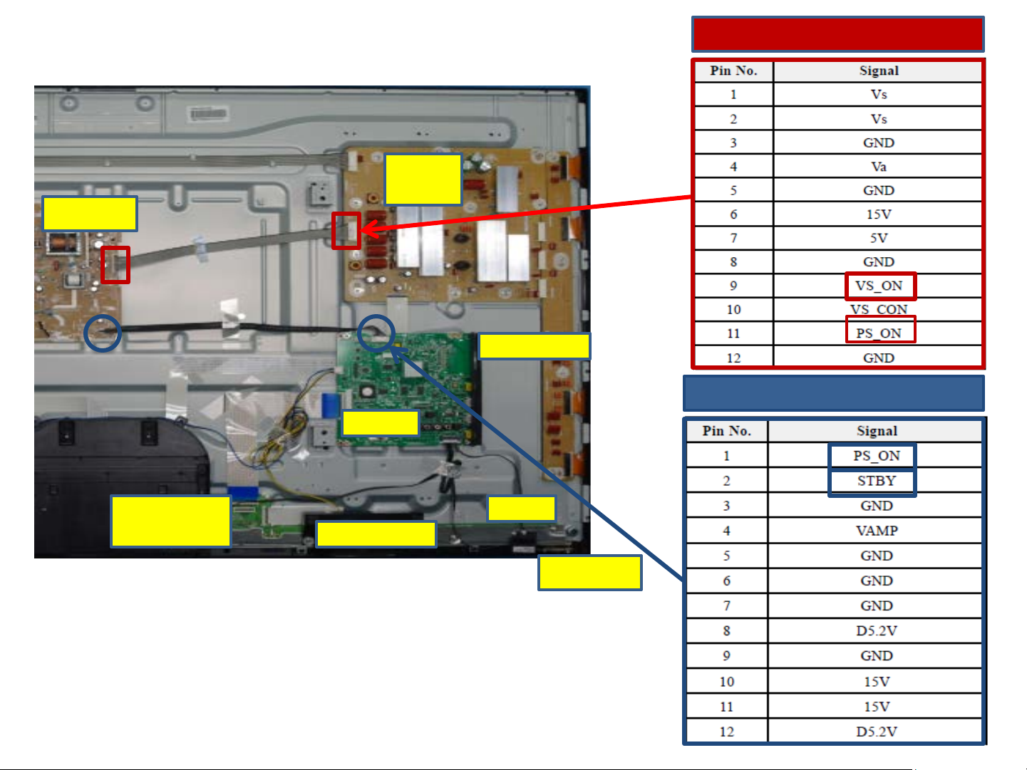
PN60E550 Power On Sequence
X-
MAIN
SMPS
X-Buffer
CN804 SMPS to CN4005 X Main
CN801 SMPS to CN201 Main
MAIN
LOGIC/Buffer
BOARD
Speaker R
Wi-Fi
1. 5V STBY SMPS to Main
2. PS_ON Main to SMPS (all Low Voltages on)
3. PS_ON SMPS thru X-Board to Logic Board
4. VS_ON Logic Board thru X-Board to SMPS
(VS & VA voltages turned on)
Wi-Fi
Jog
Func.
Jog Func.
3
Page 4
Fast Track Troubleshooting Manual
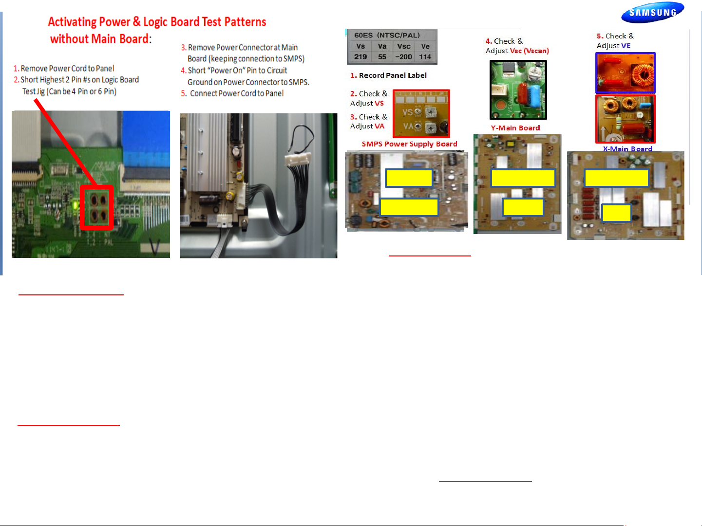
X-Main Y-Main SMPS
Power Supply Trouble Shooting Notes:
2010/2011/2012 models
Will not be run with the “X” or “Y” main disconnected. The SMPS will shut
down immediately. However if a meter is first connected to the test point
when power is applied it will read the correct voltage briefly before shut-
ting down.(You have enough time to check key voltages)
CAUTION: Do not reconnect any connectors to SMPS or Y/X Boards until
power has been turned off long enough for Vs to drop below 10V or damage
will occur to X or Y Boards. .
Over Current Protection
For the SMPS Power Supply... If a short circuit occurs on either the VS or
VA voltage lines, the SMPS stops operating, but should not fail. When the
short circuit is removed from the source line, the Power Supply will
operate normally again. Many SMPS Supplies are replaced needlessly!
Vs & Va Vsc
SAMPLE VIEW & READINGS
Ve
. VITAL SIGNS check Vs, Va, Vsc & Ve
When troubleshooting, It’s very important to first check Vs, Va, Vsc & Ve
If Vs is missing (0V), disconnect power and check for short. Use ohm meter to
measure resistance while disconnecting Y-Board & X-Board supply feeds one
at a time.
Turn Power On and Test SMPS with short connector removed for correct Vs
voltage verification. (It may only come up briefly but to full level). Again be
careful not to reconnect Power Connectors until Vs falls below 10V.
If Va is low or missing, disconnect Supply Feed to Address Boards and
Check to see if SMPS Supply is restored. (Note Va feed normally passes
through the Y-Drive to the Address Boards (Logic Buffer Boards).
If Vsc is low or missing and Vs was OK, the failure is with the Y-Board
.
since the Y-Board generate the Vsc voltage from the Vs supplied by the
SMPS.
If Ve is low or missing and Vs is OK, the failure is with the X-Board since the
Ve is generated by the X-Board from the Vs supplied by the SMPS. Please note
in some rare cases the Ve may be generated by the Y-Board feed to the XBoard.) Other SMPS Voltages:
Check Low Voltage feeds to the Main Board and other supplied Assemblies.
4
Page 5
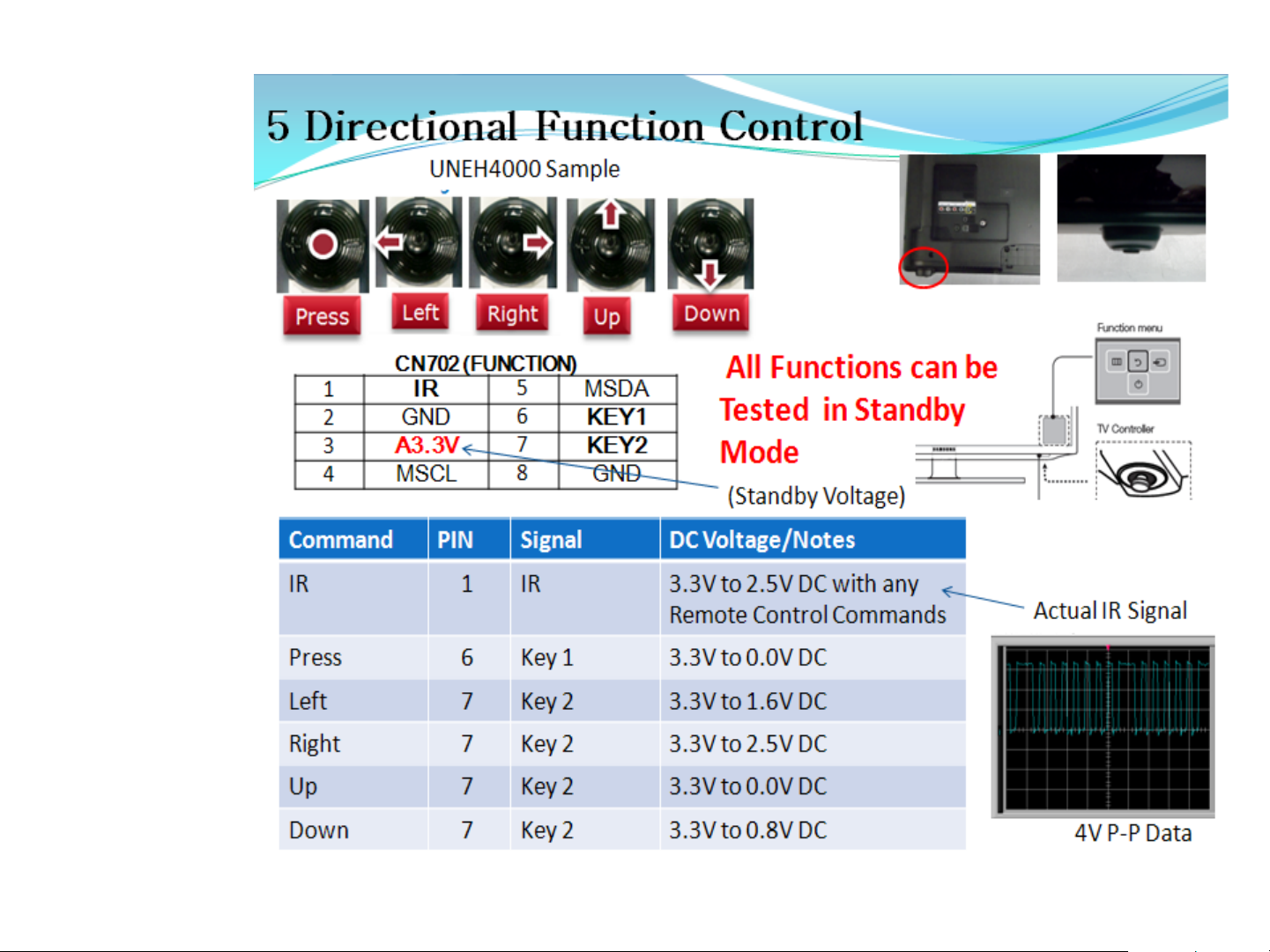
Standby A3.3V
on Function
Connector, Pin
3.
All Pins should
read 3.3V
before
commands.
Press, at Key 1,
Pin 6. 3.3V to
Function Control Troubleshooting
0.0V DC
Left, Right, Up,
Down at
Key 2, Pin 7.
Check specific
voltages on
chart.
5
Page 6
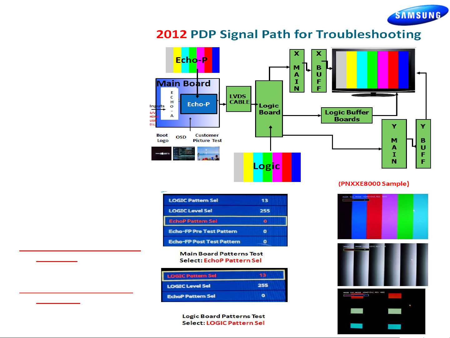
Fast Track Troubleshooting Manual (PNXXE8000 Video Signal Path Sample)
TROUBLESHOOTING VIDEO
PROBLEMS
1. Verify Video Operation:
A. Customer Picture Test
B. “Display”
C. If display & Customer Picture
Test are OK source is suspected
D. Substitute with known good
source and cabling.
2. Using Test Patterns in
Service Mode:
Customer Remote
A. Power off
B. Mute, 182, Power
Factory Remote:
A. Power On
B. Info, Test
3. Verify Echo-P Patterns
4. Verify Logic Patterns
If Logic Patterns are OK and Echo-
P are noisy, replace the
defective LVDS Cable or Main
Board.
If Echo-P and Logic Patterns are
both noisy check for specific
on screen noise error to
determine failure. (next slide)
6
Page 7
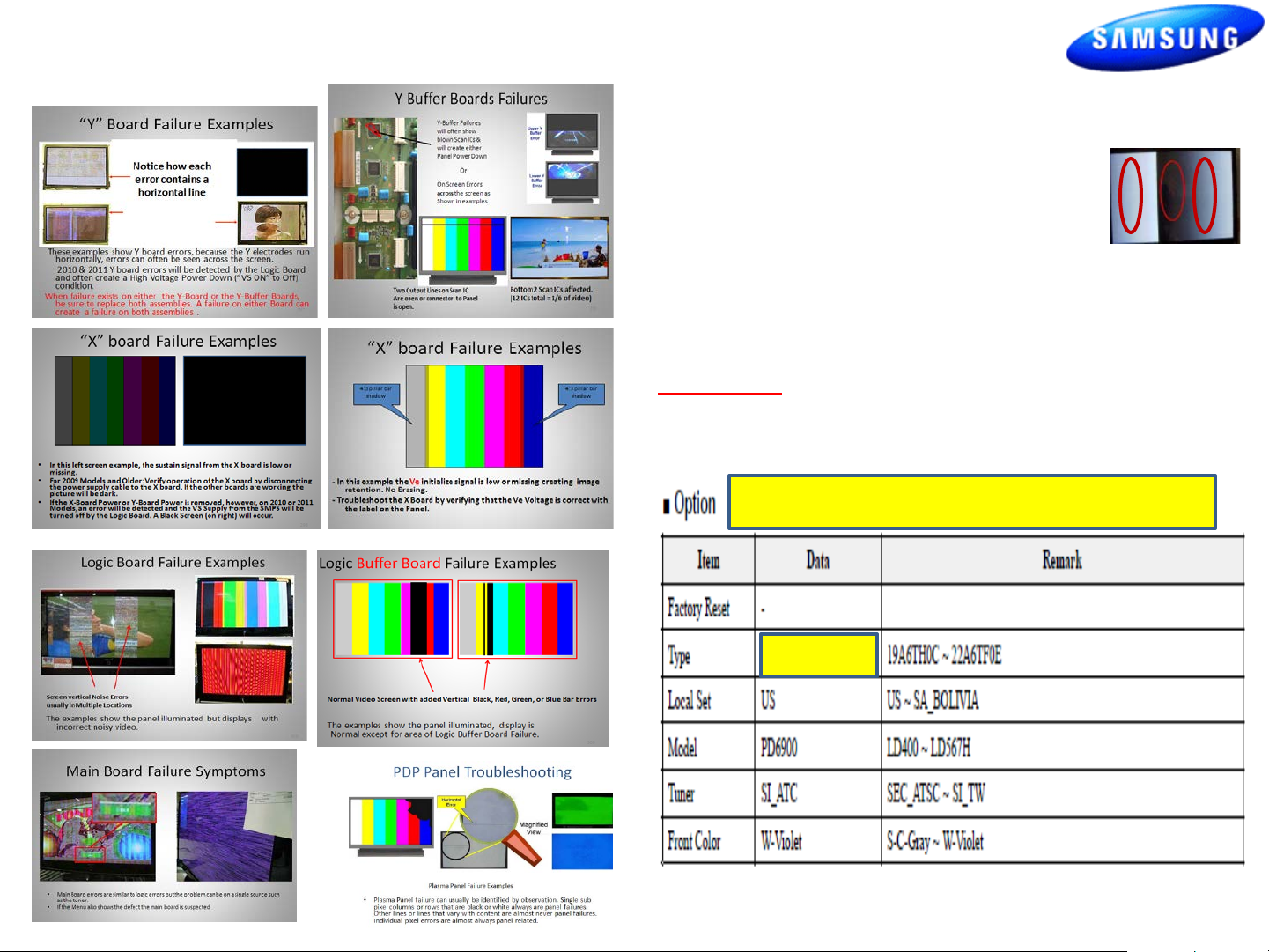
ON SCREEN FAILURE EXAMPLES:
NOTE: X/Y MAIN Combined.
Fast Track Troubleshooting Manual
ALIGNMENTS:
1. Check/Adj. VS, VA, VE, & VSC according to Panel Label
and Diffusion test. (see bulletins for any special notes
before making changes)
DIFFUSION TEST/ADJ. (cell miss-firing)
- Allow the unit to warm up 15 to 20 minutes
- Access the Burn Protect Sig. Pattern in Cust. Menu.
-Adjust the Vs volts until screen errors are gone in
both dark and bright areas.
-Adjust the Vs volts within +/- 10V on the panel label.
-
NOTE: Diffusion may appear with aging panels.
New panels
problem
2. Check/Set Option Bytes:
.
NOTE: Verify correct settings with latest tips!
with Diffusion consult bulletins and/or report
60DSArd
7
 Loading...