

Owner’s Instructions
PL-50P5H
This device is a Class B digital apparatus.
Register your product at www.samsung.com/global/register

Important Warranty Information
Regarding Television Format Viewing
Wide screen format PDP Displays (16:9, the aspect ratio of the screen width to height) are primarily
designed to view wide screen format full-motion video. The images displayed on them should primarily
be in the wide screen 16:9 ratio format, or expanded to fill the screen if your model offers this feature
and the images are constantly moving. Displaying stationary graphics and images on screen, such as
the dark side-bars on nonexpanded standard format television video and programming, should be
limited to no more than 5% of the total television viewing per week.
Additionally, viewing other stationary images and text such as stock market reports, video game
displays, station logos, web sites or computer graphics and patterns, should be limited as described
above for all televisions. Displaying stationary images that exceed the above guidelines
can cause uneven aging of PDP Displays that leave subtle, but permanent burned-in
ghost images in the PDP picture. To avoid this, vary the programming and images,
and primarily display full screen moving images, not stationary patterns or dark
bars.
On PDP models that offer picture sizing features, use these controls to view different formats as a full
screen picture.
Be careful in the selection and duration of television formats used for viewing. Uneven PDP aging as a
result of format selection and use, as well as burned-in images, are not covered by your Samsung
limited warranty.
2
User Instructions
Screen Image retention
Do not display a still image (such as on a video game) on the plasma display panel for more than
several minutes as it can cause screen image retention. This image retention is also known as
“screen burn”. To avoid such image retention, refer to page 45 of this manual to reduce the
degree of brightness and contrast of the screen when displaying a still image.
Altitude
The PDP will not operate normally at altitudes above 6500 ft.
Heat on the top of the PDP TV
The top side of the product may be hot after long periods of use as heat dissipates from the panel
through the vent hole in the upper part of the product.
This is normal and does not indicate any defect or operation failure of the product.
However, children should be prevented from touching the upper part of the product.
The product is making a ‘cracking’ noise.
A ‘cracking’ noise may occur when the product contracts or expands due to a change of
surrounding environment such as temperature or humidity. This is normal and not a defect of the
unit.
Cell Defects
The PDP uses a panel consisting of 1,230,000(SD-level) to 3,150,000(HD-level) pixels which
require sophisticated technology to produce. However, there may be few bright or dark pixels on
the screen. These pixels will have no impact on the performance of the product.
Avoid operating the TV at temperatures below 5°C (41°F)
A still image displayed too long may cause permanent damage to the PDP Panel.
Watching the PDP TV in 4:3 format for a long period of time may leave
traces of borders displayed on the left, right and center of the screen caused
by the difference of light emission on the screen.
Playing a DVD or a game console may cause similar effect to the screen.
Damages caused by the above effect are not covered by the Warranty.
Afterimage on the Screen.
Displaying still images from Video games and PC for longer than a certain period of time may
produce partial afterimages.
To prevent this effect, reduce the ‘brightness’ and ‘contrast’ when displaying still images for a
long time.
Warranty
Warranty does not cover any damage caused by image retention.
Burn-in is not covered by the warranty.
3

Table of Contents
General Information
Your New Plasma Display Panel......................8
Remote Control Buttons ................................11
Wall Installation Instructions ..........................13
How to assemble the Stand-Base ..................17
Connections
Connecting VHF and UHF Antennas ..............20
Connecting Cable TV ..................................21
Connecting a VCR ......................................23
Connecting a Camcorder ............................24
Connecting a DVD Player (480i, 480p) ........25
Connecting a DTV Receiver (480p, 720p,
1080i) ......................................................26
Connecting to HDMI (High Definition
Picture Control
Changing the Picture Standard ....................44
Customizing the Picture Settings ....................45
Viewing the DNIe Demonstration ..................47
Changing the Screen Size ............................48
Viewing the Picture-in-Picture.........................50
Setting the My Color Control Mode ...............56
Sound Control
Customizing the Sound ..............................62
Using Automatic Sound Settings ...................63
Setting the TruSurround XT............................64
Choosing a Multi-Channel Sound (MTS) track ..65
Using the Auto Volume ................................66
Setting the On/Off Melody ..........................67
Multimedia Interface) (480p, 720p, 1080i) ..27
Connecting a Digital TV Set-Top Box (480p,
720p, 1080i) ............................................28
Connecting to an Analog Amplifier ..............29
Operation
Turning the TV On and Off ..........................32
Plug & Play Feature ....................................34
Memorizing the Channels ............................37
Adding and Erasing Channels ......................39
Viewing an External Signal Source................41
4
Selecting the Internal Mute ..........................68
Channel Control
Fine Tuning Analog Channels ......................70
LNA (Low Noise Amplifier) ..........................71
Connecting a PC and Operation
Connecting a PC ........................................74
Changing the Position of the Image ..............78
Picture Quality Adjustment............................79
Image Reset ................................................82

Time Setting
Setting the Clock ........................................84
Setting the Sleep Timer ................................85
Setting the On/Off Timer..............................86
Function Description
Selecting a Menu Language ........................88
Digital Noise Reduction................................89
Setting the Blue Screen ................................90
Using the Color Weakness Enhancement
Option ......................................................91
Viewing Closed Captions ............................92
Using the Energy Saving Feature ..................93
Preventing Screen Burn-in ............................94
Reducing the Effects of Screen Burn ..............95
Appendix
Troubleshooting ..........................................98
Care and Maintenance ................................99
Specifications............................................100
Note
• The information contained in this Owner’s
Instructions is subject to change without prior
notice for improvement, and may vary
depending on the version of the TV’s software
and the regional conditions.
5


PLASMA DISPLAY PANEL
General Information
Your New Plasma Display Panel ......................................................8
Remote Control Buttons ................................................................11
Wall Installation Instructions ..........................................................13
How to assemble the Stand-Base....................................................17
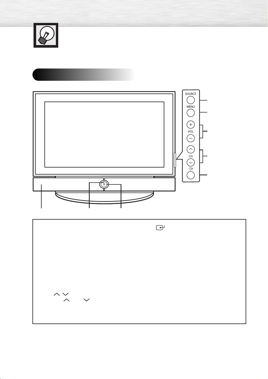
Your New Plasma Display Panel
Front Panel
Œ
´
ˇ
¨
ˆ
ΠSOURCE button
Press to display all of the available video
sources (TV, AV1, AV2, S-Video1, S-Video2,
Component1, Component2, PC, and HDMI).
´ MENU button
Displays the main on-screen menu.
ˇ VOL +, -buttons
Press to increase or decrease the volume.
Also used to select or adjust items on the
on-screen menu.
¨ CH( , ) buttons
Press CH or CH to change channels.
Also used to move up or down in the on-screen
menu.
8
∏”Ø
ˆ (Enter) button
Press to confirm a selection.
Ø Power button
Press to turn the TV on and off.
Power indicator
- Power Off : Blue
- Power On : Off
∏ Remote Control Sensor
Aim the remote control towards this spot on
the TV.
”
Speakers
Side of the TV
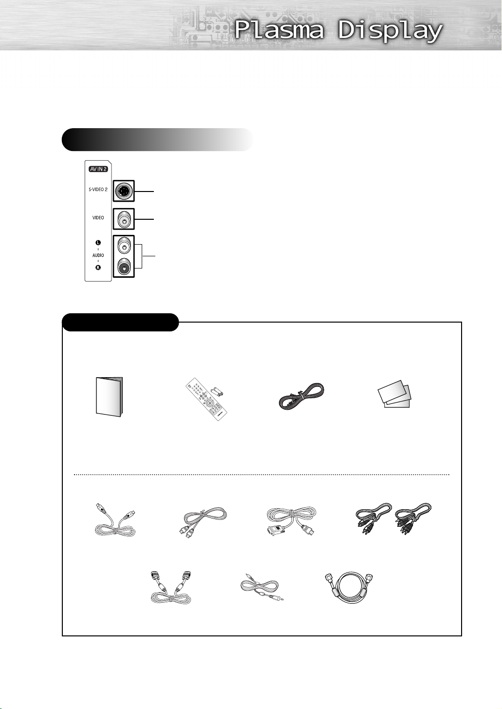
S-Video Input
Video Input
Audio Input (L, R)
Checking Accessories
Once you have unpacked your TV, check to make sure that you have all the parts shown here.
If any piece is missing or broken, call your dealer.
Owner’s Instructions
The following parts are sold separately and are available at most electronics stores.
S-VIDEO Cable
Remote Control/
HDMI Cable
PC Cable
AAA Batteries
PC Audio Cable
Power Cord Warranty Card/
Registration Card/
Safety Guide Manual
(Not available in all locations)
HDMI/DVI cable
Component Cables (RCA)
Antenna Cable
9
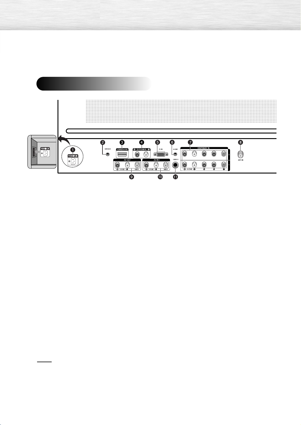
Rear Panel
ΠPOWER IN
Connect the supplied power cord.
´ SERVICE ONLY
Connector for service only.
Ø PC AUDIO IN
Connect to the audio output jack on your PC.
∏ COMPONENT IN 1, 2
Video (Y/PB/PR) and audio (L-AUDIO-R)
component inputs.
ˇ HDMI/DVI IN
Connect to the HDMI jack of a device with
HDMI output.
These inputs can also be used as a DVI
connection with separate analog audio inputs.
An optional HDMI/DVI cable will be
necessary to make this connection.
When using the optional HDMI/DVI adapter,
the DVI analog audio inputs on your TV allow
you to receive left and right audio from your
DVI device. (Not compatible with PC)
¨ DVI AUDIO IN (AUDIO-L/R)
Connect to the DVI audio output jack of an
external device.
” ANT IN
75Ω Coaxial connector for Air/Cable
Network.
’ AV OUT (VIDEO / AUDIO L/R)
Connect to the audio/video input jacks of a
recording VCR.
˝ AV IN 1 (VIDEO / AUDIO L/R)
Video and audio inputs for external devices,
such as a camcorder or VCR.
Ô S-VIDEO 1
Video input for external devices with an
S-Video output, such as a camcorder or VCR.
ˆ PC IN
Connect to the video output jack on your PC.
Notes
• Please be sure to match the color coded input terminals and cable jacks.
• For further details about connections, refer to pages 20-29.
•Whenever you connect an audio or video system to your television, ensure that all elements are
switched off. Refer to the documentation supplied with your equipment for detailed connection
instructions and associated safety precautions.
10
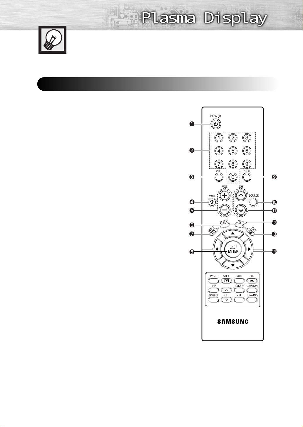
Remote Control Buttons
Remote Control
ΠPOWER button
Turns the TV on and off.
´ Number buttons
ˇ +100 button
Press to select channels over 100. For example, to select channel
121, press “+100”, then press “2” and “1.”
¨ MUTE button
Press to mute the TV sound.
ˆ VOL (Volume) buttons
Use it to adjust volume.
Ø SLEEP button
Press to select a preset time interval for automatic shutoff.
∏ MENU button
Displays the main on-screen menu.
” ENTER button
Confirms a selection.
’ PRE-CH button
Tunes to the previous channel.
˝ SOURCE button
Press to display all of the available video sources
S-Video1, S-Video2, Component1, Component2, PC, and HDMI).
Ô CH (Channel) buttons
Use it to switch channels.
INFO button
Press to display information on the TV screen.
Ò EXIT button
Press to exit the menu.
Ú Up/Down/Left/Right buttons
Control the cursor in the menu.
(TV, AV1, AV2,
Continued...
11
Æ P.SIZE button
Select Picture size. (Refer to page 48)
ı STILL button
Press to pause the current screen.
˜ PIP button
Activates picture in picture. (Refer to page 50)
¯ SOURCE button
Press to select a signal from an external source in PIP.
˘ PIP control buttons
CH
,
(These buttons change channels in the PIP window only.)
: Displays the available channels in sequence.
¿ SRS button
Selects Trusurround XT mode.
¸ MTS button
Press to choose stereo, mono or Separate Audio Program
(SAP broadcast).
˛ CAPTION button
Controls the caption decoder.
◊ P.MODE button
Adjust the TV picture by selecting one of the preset factory
settings (or select your personal, customized picture settings).
(Refer to page 44)
± E.SAVING button
Press to adjust screen brightness according to surrounding
environment. (Refer to page 93)
≠ SIZE button
Press to change the size of the PIP window.
12
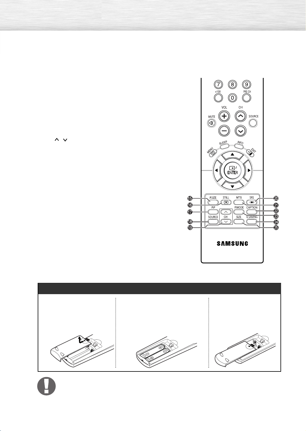
Installing the Batteries in Your Remote Control
Slide the back cover to
1
open the battery
compartment of the remote
control.
Install two AAA size batteries.
2
Make sure to match the “+” and “-”
ends of the batteries with the
diagram inside the compartment.
•Do not mix battery types, i.e.
alkaline and manganese.
Slide the cover back into
3
place.
Remote Control Operation Range
You can use your remote control within a distance of 23 feet and an angle of 30 degrees
from the left and right sides of the TV’s remote control receiver.
Wall Installation Instructions
Refer to the correct installation guide according to your wall bracket.
Installation Notes
Contact a technician for installing the wall bracket.
1
Samsung Electronics is not responsible for any damage to the product or injury to yourself
or others if you elect to perform the wall installation.
2
This product is for installing on cement walls. The product may not stay in place when
installed on plaster or wood (Ask your dealer).
3
Connect all external devices prior to installing the wall bracket.
4
The package contents and parts supplied for the wall mount are subject to change without
prior notice.
5
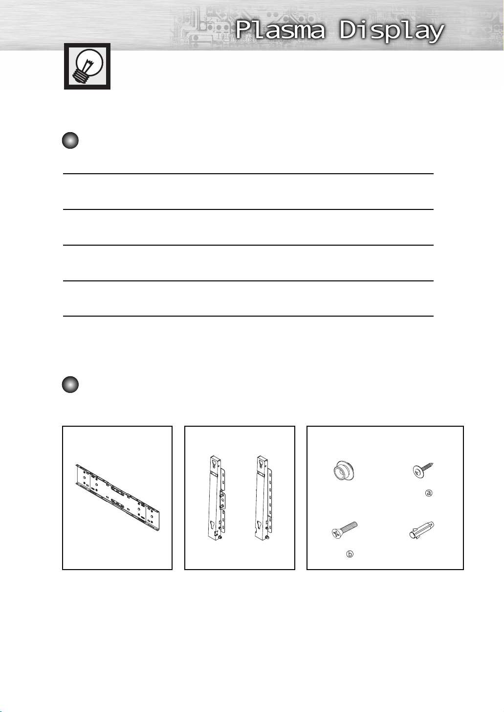
Parts (Wall attachment panel is sold separately. Check with your dealer.)
Only use the components and accessories shipped with the panel.
Wall Bracket Hinge Accessories
Plastic Hanger : 4
Screw : 4
Screw : 11
Anchor : 111 Left : 1 Right : 1
13
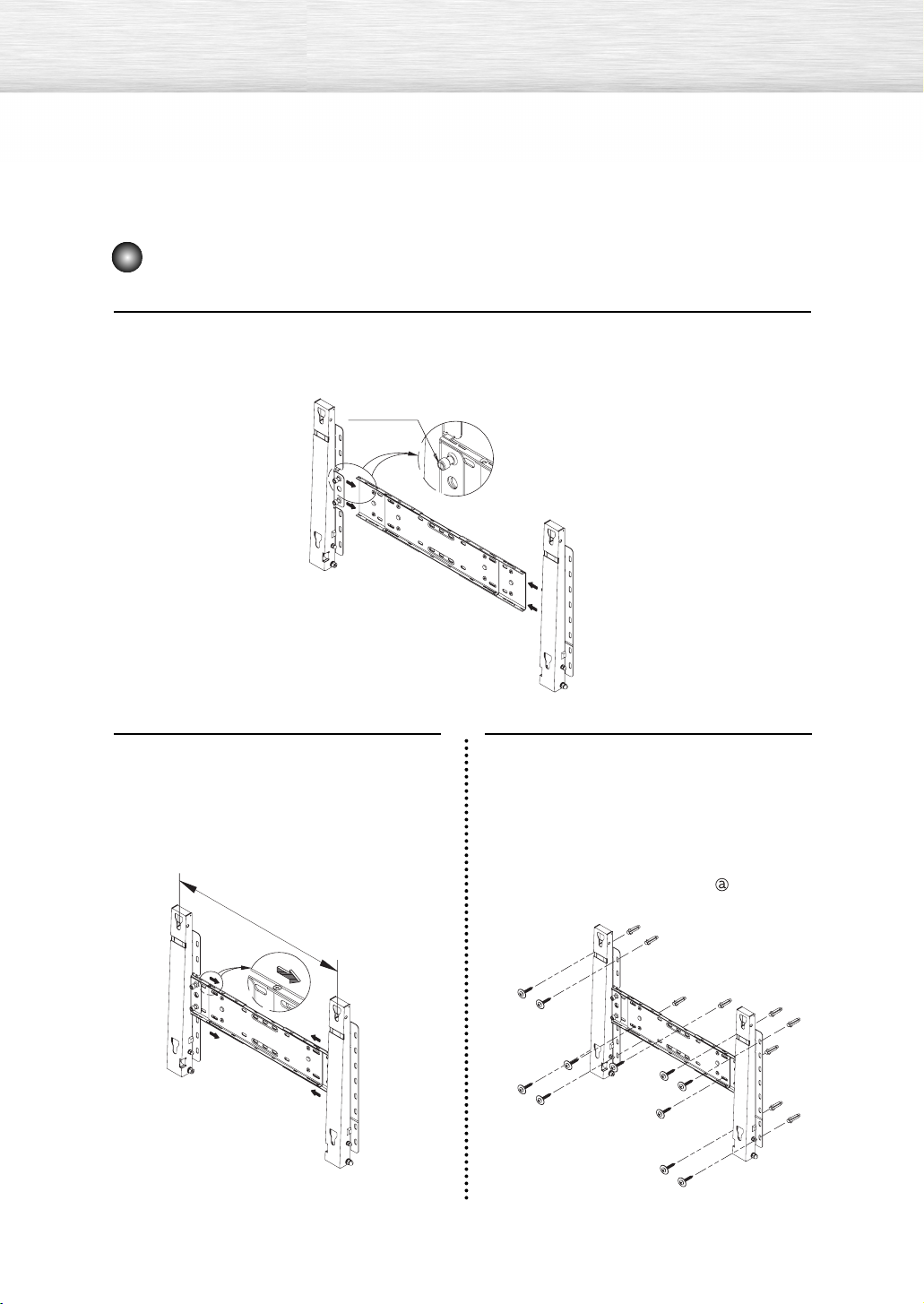
How to assemble the Wall Mount Bracket
Insert and tighten the Captive Screw in the direction of the arrow.
When done, mount the wall bracket on the wall.
1
Captive Screw
Hinge (Left)
There are two hinges
(left and right). Use the
correct one.
Before drilling into the wall, check if the
length between the two locking holes at
2
the back of the product is correct. If the
length is too short or long, loosen all or
some of the 4 screws on the wall
bracket to adjust the length.
Length between the
two locking holes
Wall Bracket
3
Hinge (Right)
Check the installation diagram and
mark the drill points on the wall.
Use the 5.0 mm bit to drill holes deeper
than 35 mm. Fix each anchor in the
corresponding hole. Match each of the
brackets and hinge holes to the
corresponding anchor holes and insert
and tighten the 11 screws .
14
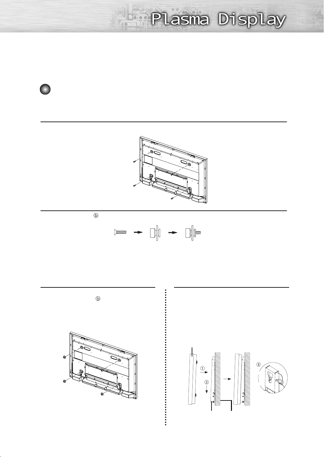
Fixing the TV panel to the wall attachment panel bracket
The shape of the product may vary depending on the model. (The assemblies of the plastic
hanger and the screw are the same)
Remove the 4 screws on the back of the product.
1
Insert the screw into the plastic hanger. (See the figure below)
2
• Mount the product on the wall bracket and make sure it is properly fixed to the left and
right plastic hangers.
• Be careful when installing the product on the bracket as fingers can be caught in the holes.
• Make sure the wall bracket is securely fixed to the wall, or the product may not stay in
place after installation.
Tighten the 4 screws in step 2 (plastic
hanger + screw ) to the rear holes of
3
the product.
Remove safety pin (#) and insert the 4
product holders into the corresponding
4
bracket holes (!). Then place the
product (@) so that it is firmly fixed to
the bracket. Make sure to reinsert and
tighten the safety pin (#) to securely
hold the product to the bracket.
PDP
Wall Bracket Wall
15
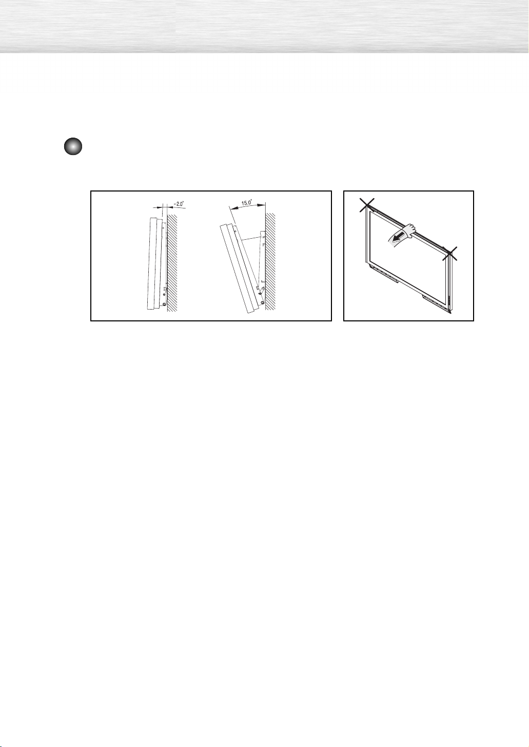
How to Adjust Mounting Angle
Note : Adjust the bracket angle to -2° before installing it on the wall.
Note
1. Fix the product to the wall bracket.
2. Hold the product at the top in the center and pull it
forward (direction of the arrow) to adjust the angle.
(See the figure to the right)
-
3. You can adjust the bracket angle between
2° and 15°.
Make sure to use the top center,
and not the left or the right side of
the product to adjust the angle.
16
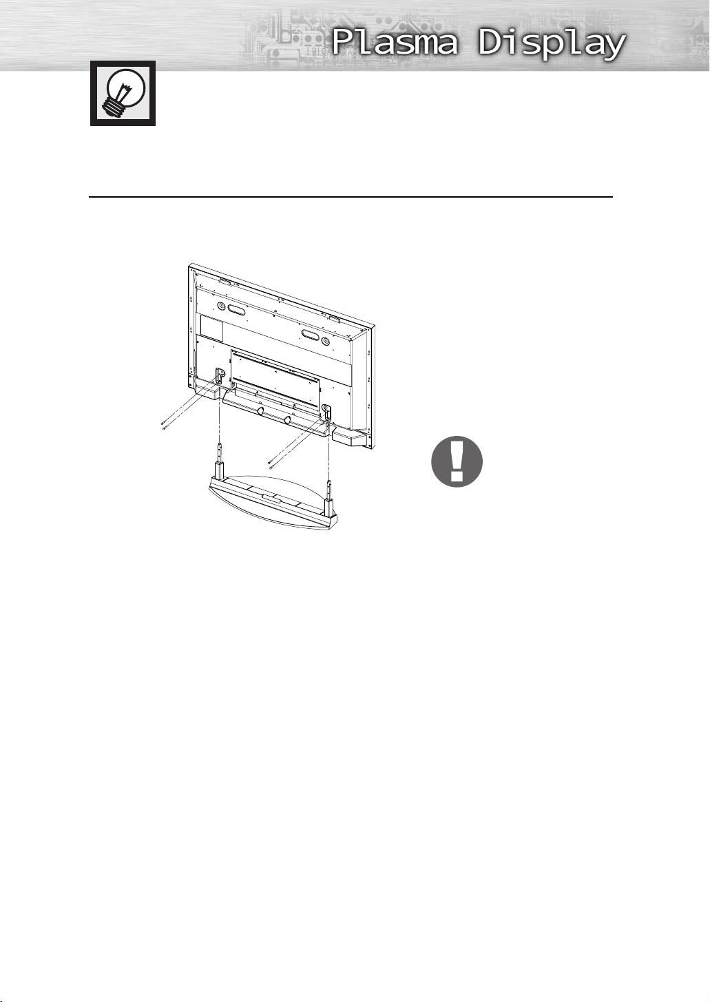
How to assemble the Stand-Base
Using the 4 screws for securing the stand pegs and the monitor, firmly attach the monitor
to the stand pegs. (The exterior of the set may be different than the picture.)
1
Warning
Firmly secure the stand to
the TV before moving it,
as the stand may fall and
could cause serious injury.
Two or more people should carry the TV. Never lay the TV on the floor because of possible damage to the screen.
➤
➤
Always store the TV upright.
17


PLASMA DISPLAY PANEL
Connections
Connecting VHF and UHF Antennas ..............................................20
Connecting Cable TV....................................................................21
Connecting a VCR........................................................................23
Connecting a Camcorder..............................................................24
Connecting a DVD Player (480i, 480p)..........................................25
Connecting a DTV Receiver (480p, 720p, 1080i) ..........................26
Connecting to HDMI (High Definition Multimedia Interface)
(480p, 720p, 1080i) ..................................................................27
Connecting a Digital TV Set-Top Box (480p, 720p, 1080i) ..............28
Connecting to an Analog Amplifier ................................................29
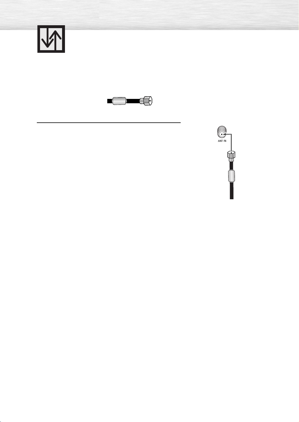
Connecting VHF and UHF Antennas
Antennas with 75-ohm Round Leads
If your antenna looks like this: it has 75-ohm round leads.
Plug the antenna lead into the ANT IN on the TV.
Use an antenna cable. (Sold Separately)
1
20
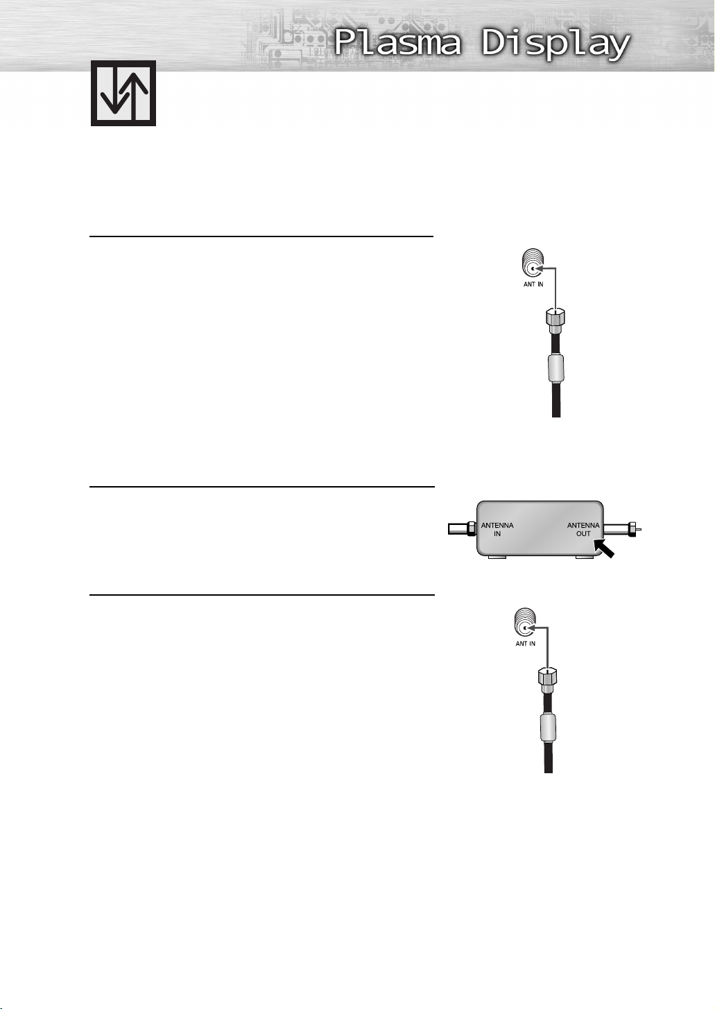
Connecting Cable TV
You can connect different cable systems to your TV, including cable without a Cable box, and cable
with a Cable box that descrambles some or all channels.
Cable without a Cable Box
Plug the incoming cable into the ANT IN on the TV.
Use an antenna cable. (Sold Separately)
1
Cable with a Cable Box that Descrambles All Channels
Find the cable connected to the ANTENNA OUT
terminal on your Cable box. This terminal might be
1
labeled “ANT OUT”, “VHF OUT” or simply “OUT”.
Connect the cable to the ANT IN on the TV.
Use an antenna cable. (Sold Separately)
2
Cable Box
21
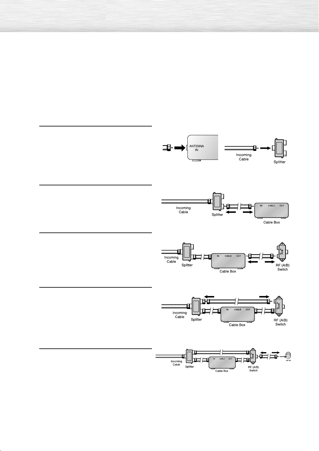
Cable with a Cable Box that Descrambles Some (But Not All) Channels
To complete this connection you will need a two-way splitter, an RF (A/B) switch, and four coaxial
cables (which you can buy from your Samsung dealer or any electronics store).
Find and disconnect the cable that is
connected to the ANTENNA IN terminal
1
of your Splitter. This terminal might
be labeled “ANT IN”, “VHF IN” or
simply, “IN”. Connect this cable to a
two-way splitter.
Connect a coaxial cable between an
OUT terminal of the splitter and the
2
IN terminal of the Cable box.
Connect a coaxial cable between the
ANTENNA OUT terminal of the Cable
3
box and the B-IN terminal of the RF
(A/B) switch.
Connect another cable between the
other OUT terminal on the splitter and
4
the A–IN terminal on the RF (A/B)
switch.
Connect the last coaxial cable between
the OUT terminal of the RF (A/B)
5
switch and the ANT IN on the TV.
After you've made this connection, set the A/B switch to the “A” position for normal viewing.
Set the A/B switch to the “B” position to view scrambled channels. (When you set the A/B switch to
“B”, you will need to tune your Set-Top Box to the Cable box's output channel, which is usually
channel 3 or 4.)
22
Connecting a VCR
Connecting a VCR to the Video or S-Video/Audio jack
TV Rear Panel
VCR
Power cord
Audio cable
Video cable
S-Video cable
How to Connect
Connect the Video/Audio cables between the VIDEO or S-VIDEO/AUDIO input jacks on the
TV and VIDEO or S-VIDEO/AUDIO output jacks on the VCR.
(Note: For better video, use an S-Video cable.)
Note
• Please be sure to match the color coded input terminals and cable jacks.
Videotape Playback:
1. Turn on your TV.
2. Press the SOURCE button to select “Video (AV1 or AV2)” or “S-Video (S-Video1 or S-Video2)”.
3. Turn on your VCR, insert a videotape and press the Play button.
23
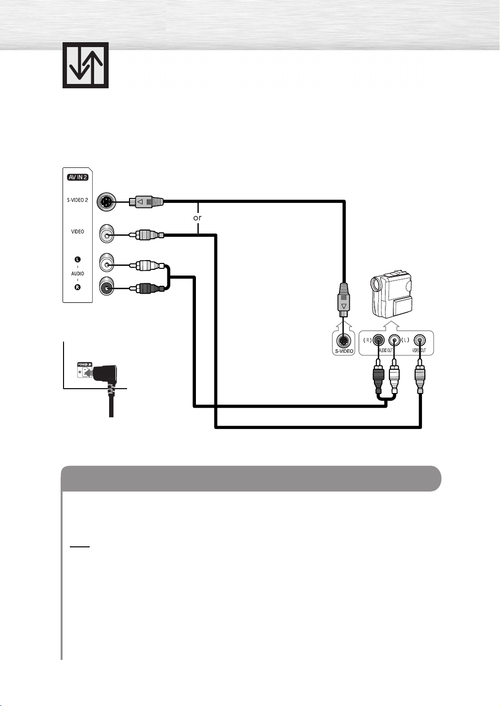
Connecting a Camcorder
Viewing camcorder tapes
Side of the TV
TV Rear Panel
S-Video cable
Camcorder
Audio cable
Power cord
Video cable
How to Connect
Connect a Video/Audio cable between the VIDEO or S-VIDEO/AUDIO input jacks on the TV
and the VIDEO or S-VIDEO/AUDIO output jacks on the camcorder.
(Note: For better video, use an S-VIDEO cable.)
Note
• Please be sure to match the color coded input terminals and cable jacks.
Viewing Tapes
1. Turn on your TV.
2. Press the SOURCE button to select “Video (AV1 or AV2)” or “S-Video (S-Video1 or S-Video2)”.
3. Turn on your camcorder and set it to video mode. (For details, refer to your camcorder
owner’s instructions.)
4. Set the IN/OUT switch on your camcorder to OUT.
5. Insert the tape into the camcorder and press the Play button.
24
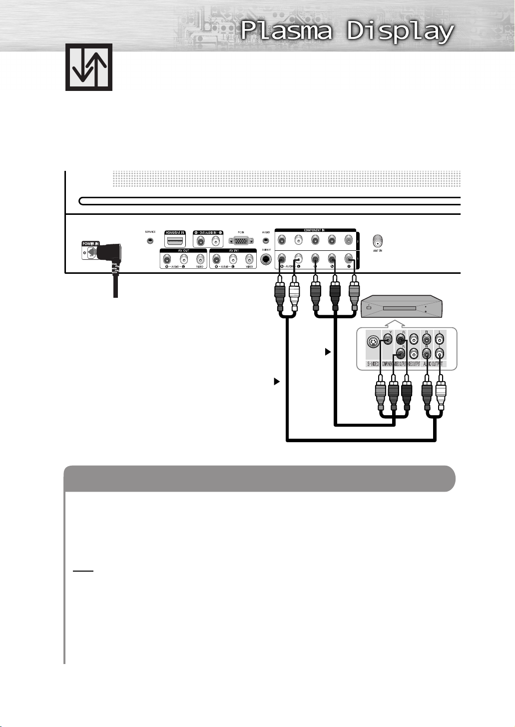
Connecting a DVD Player (480i, 480p)
Playing DVD
TV Rear Panel
Power cord
DVD Player
1
2
Component cable
Audio cable
How to Connect
Connect the Y, PB, PR (COMPONENT1, 2) input jacks on the TV to the Y, PB, PR output jacks
1
on the DVD player using a component cable.
Connect the AUDIO L/R (COMPONENT1, 2) input jacks on the TV to the AUDIO output
2
jacks on the DVD player using a audio cable.
Note
• Please be sure to match the color coded input terminals and cable jacks.
To Play DVD:
1. Turn on your TV.
2. Press the SOURCE button to select “Component 1” or “Component 2”.
3. Turn on your DVD player, insert a DVD disc and press the Play button.
• For an explanation of component video, see your DVD player’s owner’s instructions.
25
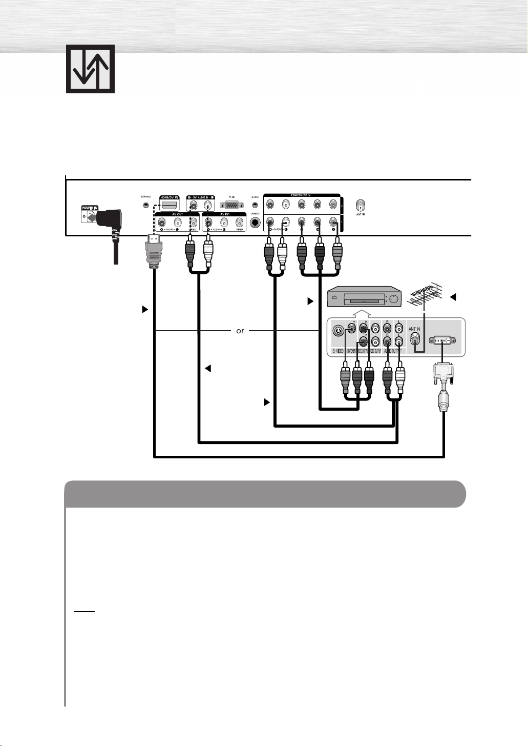
Connecting a DTV Receiver (480p, 720p, 1080i)
This TV displays the optimum picture in 720p mode.
Watching DTV
TV Rear Panel
Power cord
DTV Receiver
2
2
3
3
Component cable
Audio cable
HDMI/DVI cable
How to Connect
Connect the cable or antenna to the antenna input jack on the DTV.
1
Connect the Y, P
2
DVI output jacks on the DTV receiver using a component or HDMI/DVI cable.
B, PR (COMPONENT1, 2) or HDMI/DVI input jack on the TV to the Y, PB, PR or
1
Connect the AUDIO L/R (COMPONENT1, 2 or DVI AUDIO IN) input jacks on the TV with
3
the AUDIO output jacks on the DTV receiver using an audio cable.
Note
• Please be sure to match the color coded input terminals and cable jacks.
To Watch DTV:
1. Turn on your TV.
2. Turn on your DTV receiver.
• For an explanation of component video, see your DTV receiver owner’s instructions.
3. Press the SOURCE button to select “Component1”, “Component2” or “HDMI”.
26
Connecting to HDMI (High Definition
Multimedia Interface) (480p, 720p, 1080i)
Watching DTV
TV Rear Panel
Power cord
HDMI cable
DTV Set-Top Box
2
1
How to Connect
Connect the cable or antenna to the antenna input jack on the DTV.
1
Connect the HDMI/DVI input jack on the TV with the HDMI output jack on the DTV Set-Top Box
2
using an HDMI cable.
Note
• Please make sure the HDMI source’s power is on before selecting HDMI from the “Source List”
on the TV.
To Watch DTV:
1. Turn on your TV.
2. Turn on your DTV receiver.
• For an explanation of HDMI video, see your DTV receiver owner’s instructions.
3. Press the SOURCE button to select “HDMI”.
27
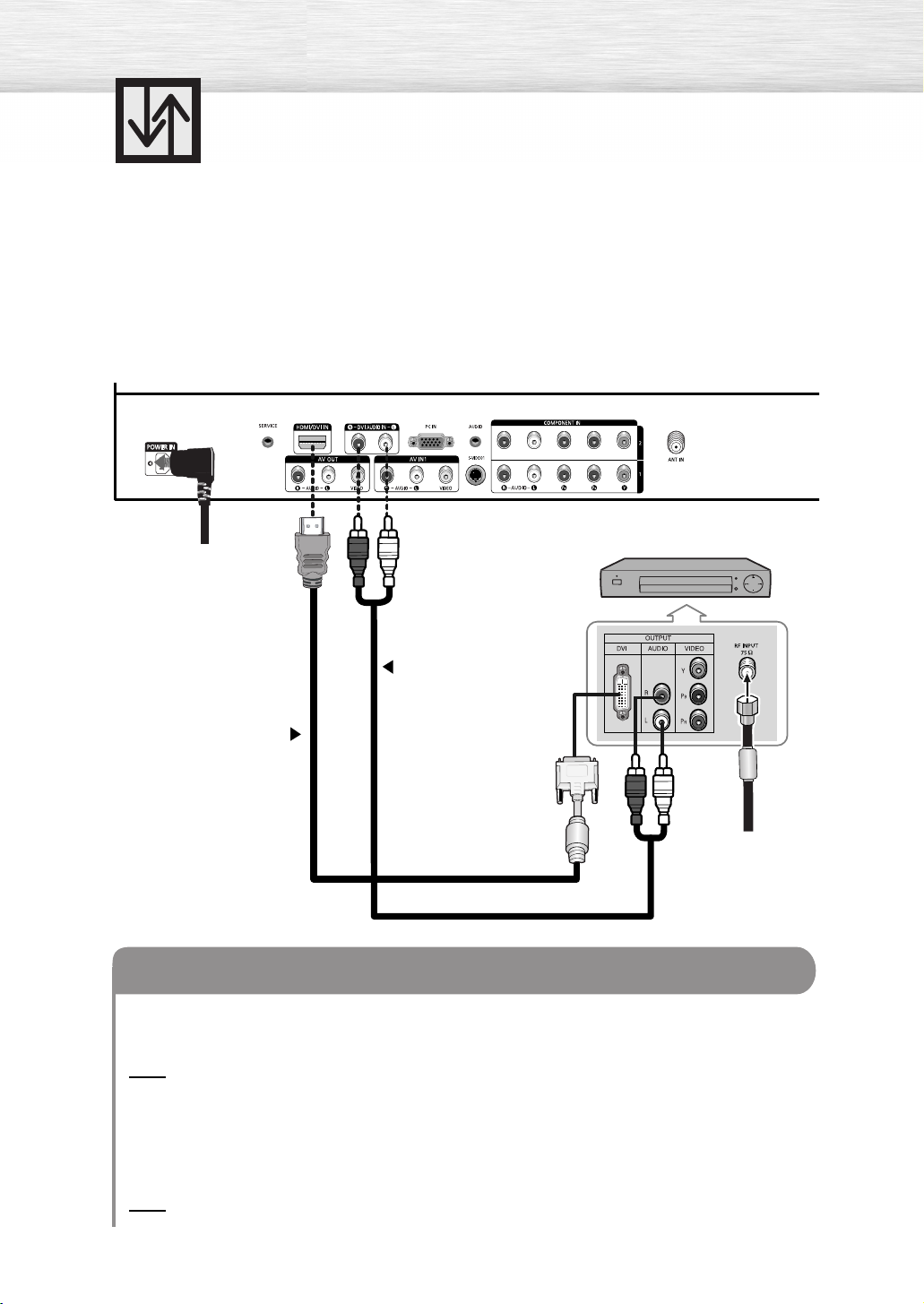
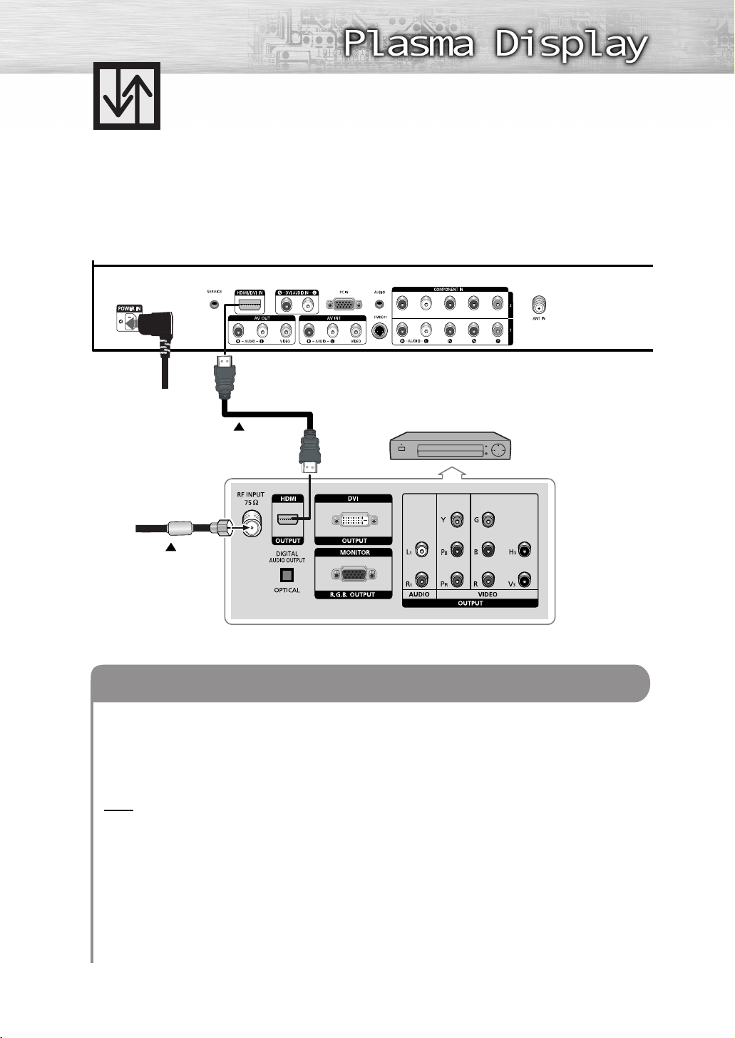
Connecting a Digital TV Set-Top Box
(480p, 720p, 1080i)
By inputting a high-bandwidth digital content protection High-Definition picture source
to the HDMI input jack on the TV, High-Definition pictures can be displayed on the
screen in their digital form.
Connecting to HDMI (High Definition Multimedia Interface)/DVI Compatible
TV Rear Panel
Power cord
DTV Set-Top Box
1
2
From cable
HDMI/DVI cable
Audio cable
How to Connect
Connect the DVI AUDIO (L, R) input jacks on the TV with the AUDIO output jacks on the
1
Set-Top Box using an audio cable.
Note
•Use analog stereo audio inputs when using the HDMI input with a device that outputs
DVI instead of HDMI.
or Antenna
Connect the HDMI/DVI input jack on the TV and the DVI output jack on the Set-Top Box
2
using an HDMI/DVI cable.
Note
• The HDMI/DVI IN jack is not compatible with PC.
28
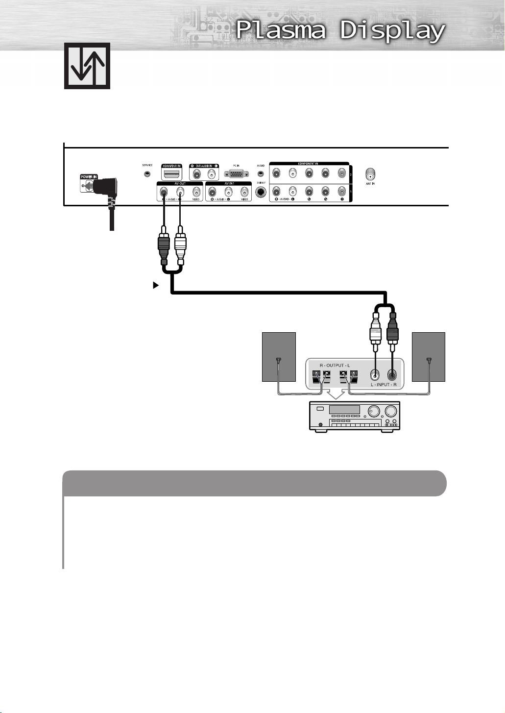
TV Rear Panel
Power cord
Connecting to an Analog Amplifier
Audio cable
1
Analog Amplifier
How to Connect
The “AV OUT (AUDIO L/R)” terminals cannot be used for external speakers.
1
You must hook them up to an amplifier.
When an audio amplifier is connected to the “AV OUT (AUDIO L/R)” terminals:
Decrease the gain (volume) of the TV, and adjust the volume level with the Amplifier’s volume
control.
29

 Loading...