

Page 1

Owner’s Instructions
PL-42P5H
PL-50P5H
This device is a Class B digital apparatus.
Register your product at www.samsung.com/global/register
Page 2

Información importante sobre la garantía
relativa al formato de visualización del televisor
Las pantallas PDP con formato de pantalla panorámica (16:9, la relación de aspecto ancho:alto de la
pantalla) están diseñadas principalmente para visualizar vídeos de movimiento de formato
panorámico. Las imágenes deben estar principalmente en el formato panorámico de relación 16:9, o
ampliadas para llenar la pantalla si el modelo tiene esta opción, y las imágenes están en movimiento
constante. La visualización de imágenes y gráficos estáticos en la pantalla, como las barras oscuras
laterales en programación y vídeos de televisión en formato estándar no ampliados, debe limitarse a
no más del 5% del tiempo total de visualización del televisor por semana.
Además, la visualización de otras imágenes estáticas y texto, como los informes de bolsa, pantallas de
videojuegos, logotipos de emisoras, sitios Web o gráficos y dibujos de ordenador, deberá limitarse en
todos los televisores como ya se ha descrito. La visualización de imágenes estáticas que
supere los límites de las instrucciones anteriores puede producir un envejecimiento
desigual de las pantallas PDP, lo que provocará una reproducción superpuesta sutil
pero permanente de la imagen de la PDP. Para evitarlo, varíe la programación y las
imágenes y, sobre todo, visualice imágenes en movimiento a toda pantalla, no
gráficos estáticos ni barras oscuras.
En modelos de PDP que ofrezcan opciones para el tamaño de la imagen, utilice estos controles para
ver los distintos formatos como imagen a toda pantalla.
Tenga cuidado en la selección y duración de los formatos de televisión utilizados para la visualización.
La garantía limitada de Samsung no cubre el envejecimiento desigual de la PDP como resultado de la
selección y uso de formatos, así como otras imágenes retenidas.
2
Page 3

User Instructions
Screen Image retention
Do not display a still image (such as on a video game) on the plasma display panel for more than
several minutes as it can cause screen image retention. This image retention is also known as
“screen burn”. To avoid such image retention, refer to page 47 of this manual to reduce the
degree of brightness and contrast of the screen when displaying a still image.
Altitude
The PDP will not operate normally at altitudes above 6500 ft.
Heat on the top of the PDP TV
The top side of the product may be hot after long periods of use as heat dissipates from the panel
through the vent hole in the upper part of the product.
This is normal and does not indicate any defect or operation failure of the product.
However, children should be prevented from touching the upper part of the product.
The product is making a ‘cracking’ noise.
A ‘cracking’ noise may occur when the product contracts or expands due to a change of
surrounding environment such as temperature or humidity. This is normal and not a defect of the
unit.
Cell Defects
The PDP uses a panel consisting of 1,230,000(SD-level) to 3,150,000(HD-level) pixels which
require sophisticated technology to produce. However, there may be few bright or dark pixels on
the screen. These pixels will have no impact on the performance of the product.
Avoid operating the TV at temperatures below 5°C(41°F)
A still image displayed too long may cause permanent damage to the PDP Panel.
Watching the PDP TV in 4:3 format for a long period of time may leave
traces of borders displayed on the left, right and center of the screen caused
by the difference of light emission on the screen.
Playing a DVD or a game console may cause similar effect to the screen.
Damages caused by the above effect are not covered by the Warranty.
Afterimage on the Screen.
Displaying still images from Video games and PC for longer than a certain period of time may
produce partial afterimages.
To prevent this effect, reduce the ‘brightness’ and ‘contrast’ when displaying still images for a
long time.
Warranty
Warranty does not cover any damage caused by image retention.
Burn-in is not covered by the warranty.
3
Page 4

Table of Contents
General Information
Your New Plasma Display Panel......................8
Remote Control Buttons ................................11
Wall Installation Instructions ..........................13
How to assemble the Stand-Base ..................17
Connections
Connecting VHF and UHF Antennas ..............20
Connecting Cable TV ..................................21
Connecting a VCR ......................................23
Connecting a Camcorder ............................24
Connecting a DVD Player (480i, 480p) ........25
Connecting a DTV Receiver (480p, 720p,
1080i) ......................................................26
Connecting to HDMI (High Definition
Multimedia Interface) (480p, 720p, 1080i) ..27
Picture Control
Changing the Picture Standard ....................46
Customizing the Picture Settings ....................47
Viewing the DNIe Demonstration ..................49
Changing the Screen Size ............................50
Viewing the Picture-in-Picture.........................52
Setting the My Color Control Mode ...............58
Sound Control
Customizing the Sound ..............................64
Using Automatic Sound Settings ...................65
Setting the TruSurround XT............................66
Choosing a Multi-Channel Sound (MTS) track ..67
Using the Auto Volume ................................68
Setting the On/Off Melody ..........................69
Connecting a Digital TV Set-Top Box (480p,
720p, 1080i) ............................................28
Connecting to an Analog Amplifier ..............29
Operation
Turning the TV On and Off ..........................32
Plug & Play Feature ....................................34
Memorizing the Channels ............................37
Adding and Erasing Channels ......................39
Setting Up Your Remote Control ....................41
Viewing an External Signal Source................43
4
Selecting the Internal Mute ..........................70
Channel Control
Fine Tuning Analog Channels ......................72
LNA (Low Noise Amplifier) ..........................73
Connecting a PC and Operation
Connecting a PC ........................................76
Changing the Position of the Image ..............80
Picture Quality Adjustment............................81
Image Reset ................................................84
Page 5

Time Setting
Setting the Clock ........................................86
Setting the Sleep Timer ................................87
Setting the On/Off Timer..............................88
Function Description
Selecting a Menu Language ........................90
Digital Noise Reduction................................91
Setting the Blue Screen ................................92
Using the Color Weakness Enhancement
Option ......................................................93
Viewing Closed Captions ............................94
Using the Energy Saving Feature ..................95
Preventing Screen Burn-in ............................96
Reducing the Effects of Screen Burn ..............97
Using the V-Chip (for USA) ..........................98
Using the V-Chip (for Canada)....................104
Appendix
Troubleshooting ........................................114
Care and Maintenance ..............................115
Specifications............................................116
Note
• The information contained in this Owner’s
Instructions is subject to change without prior
notice for improvement, and may vary
depending on the version of the TV’s software
and the regional conditions.
5
Page 6

Page 7

PLASMA DISPLAY PANEL
General Information
Your New Plasma Display Panel ......................................................8
Remote Control Buttons ................................................................11
Wall Installation Instructions ..........................................................13
How to assemble the Stand-Base....................................................17
Page 8
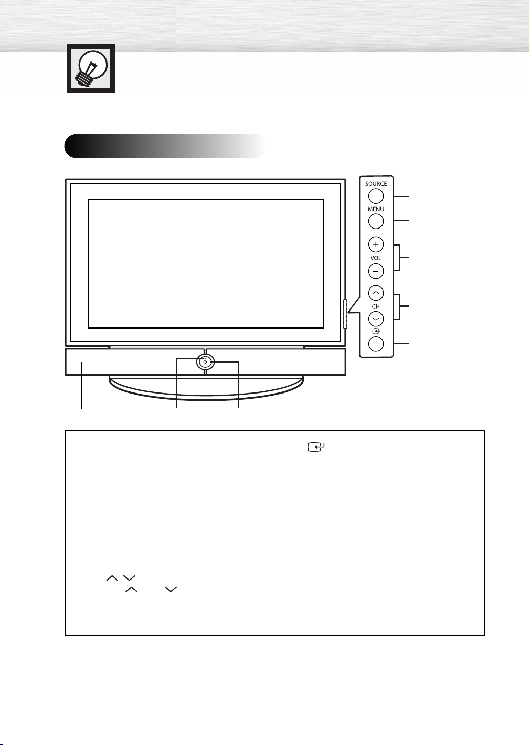
Your New Plasma Display Panel
Front Panel
Œ
´
ˇ
¨
ˆ
ΠSOURCE button
Press to display all of the available video
sources (TV, AV1, AV2, S-Video1, S-Video2,
Component1, Component2, PC, and HDMI).
´ MENU button
Displays the main on-screen menu.
ˇ VOL +, -buttons
Press to increase or decrease the volume.
Also used to select or adjust items on the
on-screen menu.
¨ CH( , ) buttons
Press CH or CH to change channels.
Also used to move up or down in the on-screen
menu.
8
∏”Ø
ˆ (Enter) button
Press to confirm a selection.
Ø Power button
Press to turn the TV on and off.
Power indicator
- Power Off : Blue
- Power On : Off
∏ Remote Control Sensor
Aim the remote control towards this spot on
the TV.
”
Speakers
Page 9
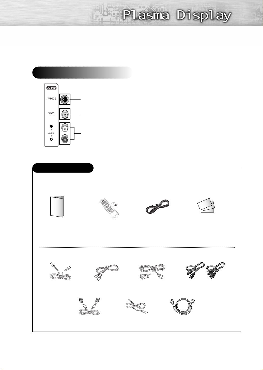
Side of the TV
S-Video Input
Video Input
Audio Input (L, R)
Checking Accessories
Once you have unpacked your TV, check to make sure that you have all the parts shown here.
If any piece is missing or broken, call your dealer.
Owner’s Instructions
The following parts are sold separately and are available at most electronics stores.
S-VIDEO Cable
Remote Control/
HDMI Cable
PC Cable
AAA Batteries
PC Audio Cable
Power Cord Warranty Card/
Registration Card/
Safety Guide Manual
(Not available in all locations)
HDMI/DVI cable
Component Cables (RCA)
Antenna Cable
9
Page 10

Rear Panel
ΠPOWER IN
Connect the supplied power cord.
´ SERVICE ONLY
Connector for service only.
Ø PC AUDIO IN
Connect to the audio output jack on your PC.
∏ COMPONENT IN 1, 2
Video (Y/PB/PR) and audio (L-AUDIO-R)
component inputs.
ˇ HDMI/DVI IN
Connect to the HDMI jack of a device with
HDMI output.
These inputs can also be used as a DVI
connection with separate analog audio inputs.
An optional HDMI/DVI cable will be
necessary to make this connection.
When using the optional HDMI/DVI adapter,
the DVI analog audio inputs on your TV allow
you to receive left and right audio from your
DVI device. (Not compatible with PC)
¨ DVI AUDIO IN (AUDIO-L/R)
Connect to the DVI audio output jack of an
external device.
” ANT IN
75Ω Coaxial connector for Antenna/Cable
Network.
’ AV OUT (VIDEO / AUDIO L/R)
Outputs for external devices.
˝ AV IN 1 (VIDEO / AUDIO L/R)
Video and audio inputs for external devices,
such as a camcorder or VCR.
Ô S-VIDEO 1
Video input for external devices with an
S-Video output, such as a camcorder or VCR.
ˆ PC IN
Connect to the video output jack on your PC.
Notes
• Please be sure to match the color coded input terminals and cable jacks.
• For further details about connections, refer to pages 20-29.
• Whenever you connect an audio or video system to your television, ensure that all elements are
switched off. Refer to the documentation supplied with your equipment for detailed connection
instructions and associated safety precautions.
10
Page 11
Remote Control Buttons
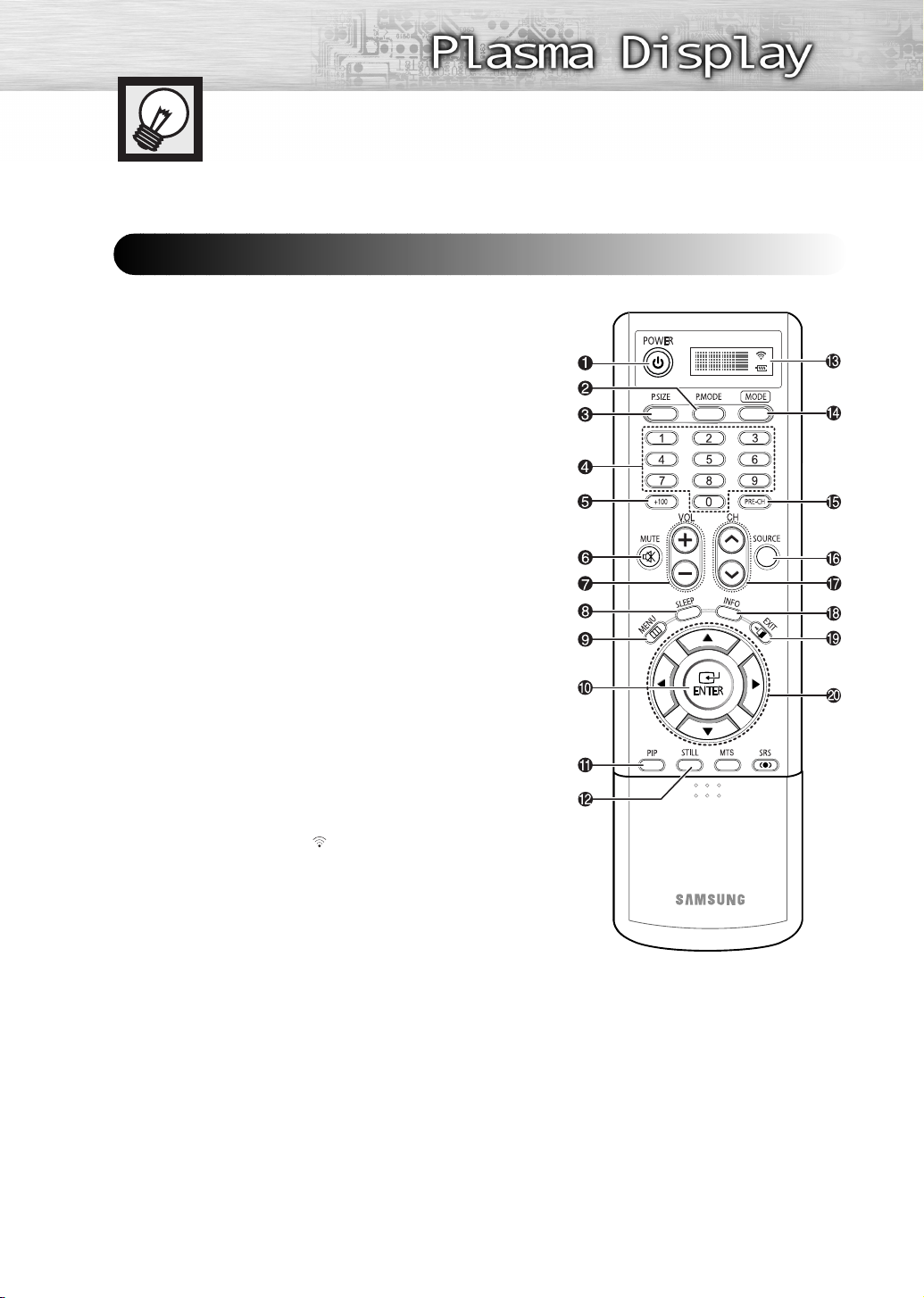
Remote Control
ΠPOWER button
Turns the TV on and off.
´ P.MODE button
Adjust the TV picture by selecting one of the preset factory settings
(or select your personal, customized picture settings).
(Refer to page 46)
ˇ P.SIZE button
Select Picture size. (Refer to page 50)
¨ Number buttons
ˆ +100 button
Press to select channels over 100. For example, to select channel
121, press “+100”, then press “2” and “1.”
Ø MUTE button
Press to mute the TV sound.
∏ VOL (Volume) buttons
Use it to adjust volume.
” SLEEP button
Press to select a preset time interval for automatic shutoff.
’ MENU button
Displays the main on-screen menu.
˝ ENTER button
Confirms a selection.
Ô PIP button
Activates picture in picture. (Refer to page 52)
STILL button
Press to pause the current screen.
Ò LCD DISPLAY
When you press a button, ‘ ‘ appears along with selected mode
(TV, VCR, CATV, DVD or STB) and the remote's battery charge
status.
Ú MODE button
Selects a target device to be controlled by the Samsung remote
control (i.e., VCR, Cable, DVD players or Samsung STB). If you
change modes, the new mode is momentarily displayed on LCD.
Æ PRE-CH button
Tunes to the previous channel.
ı SOURCE button
Press to display all of the available video sources
S-Video1, S-Video2, Component1, Component2, PC, and HDMI).
˜ CH (Channel) buttons
Use it to switch channels.
¯ INFO button
Press to display information on the TV screen.
˘ EXIT button
Press to exit the menu.
¿ Up/Down/Left/Right buttons
Control the cursor in the menu. Continued...
(TV, AV1, AV2,
11
Page 12
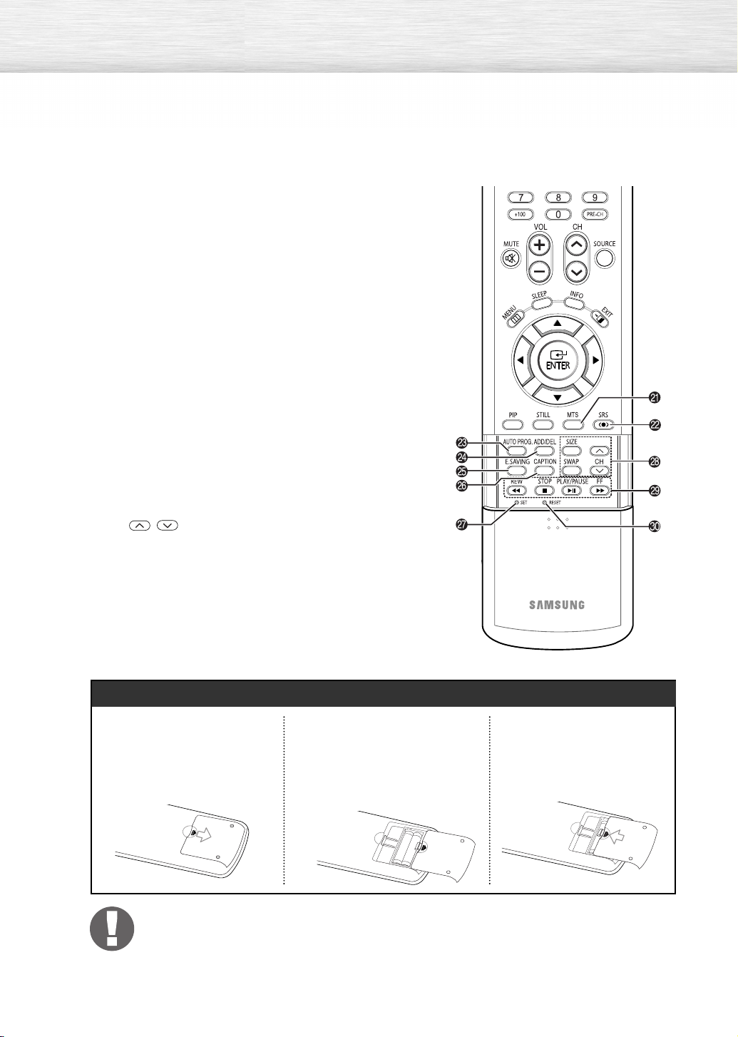
¸ MTS button
Press to choose stereo, mono or Separate Audio Program
(SAP broadcast).
˛ SRS button
Selects Trusurround XT mode.
◊ AUTO PROG. button
The TV automatically cycles through all of the available channels
and stores them in memory.
± ADD/DEL button
Press to add or delete channels in the TV’s memory.
≠ E.SAVING button
Press to adjust screen brightness according to surrounding
environment. (Refer to page 95)
– CAPTION button
Controls the caption decoder.
— SET button
Used during set up of this Samsung remote control, so that it will
work compatibly with other devices (VCR, Cable Box and DVD).
÷ PIP control buttons
Size: Press to make the PIP window Large, Small or Double.
Swap: Exchanges the video signal that is currently displayed on
the main screen with the signal in the PIP window.
,
CH
(These buttons change channels in the PIP window only.)
: Displays the available channels in sequence.
® VCR, DVD control buttons
Controls VCR tape or DVD disc functions: Stop, Rewind,
Play/Pause, and Fast Forward.
∑ RESET button
If your remote control is not functioning properly, take out the
batteries and press the reset button for about 2~3 seconds.
Re-insert the batteries and try using the remote control again.
12
Installing the Batteries in Your Remote Control
Slide the back cover to
1
open the battery
compartment of the remote
control.
Install two AAA size batteries.
2
Make sure to match the “+” and
“-” ends of the batteries with the
diagram inside the compartment.
•Do not mix battery types, i.e.
alkaline and manganese.
Slide the cover back into
3
place.
Remote Control Operation Range
You can use your remote control within a distance of 23 feet and an angle of 30 degrees
from the left and right sides of the TV’s remote control receiver.
Page 13
Wall Installation Instructions
Refer to the correct installation guide according to your wall bracket.
Installation Notes
Contact a technician for installing the wall bracket.
1
Samsung Electronics is not responsible for any damage to the product or injury to yourself
or others if you elect to perform the wall installation.
2
This product is for installing on cement walls. The product may not stay in place when
installed on plaster or wood (Ask your dealer).
3
Connect all external devices prior to installing the wall bracket.
4
The package contents and parts supplied for the wall mount are subject to change without
prior notice.
5
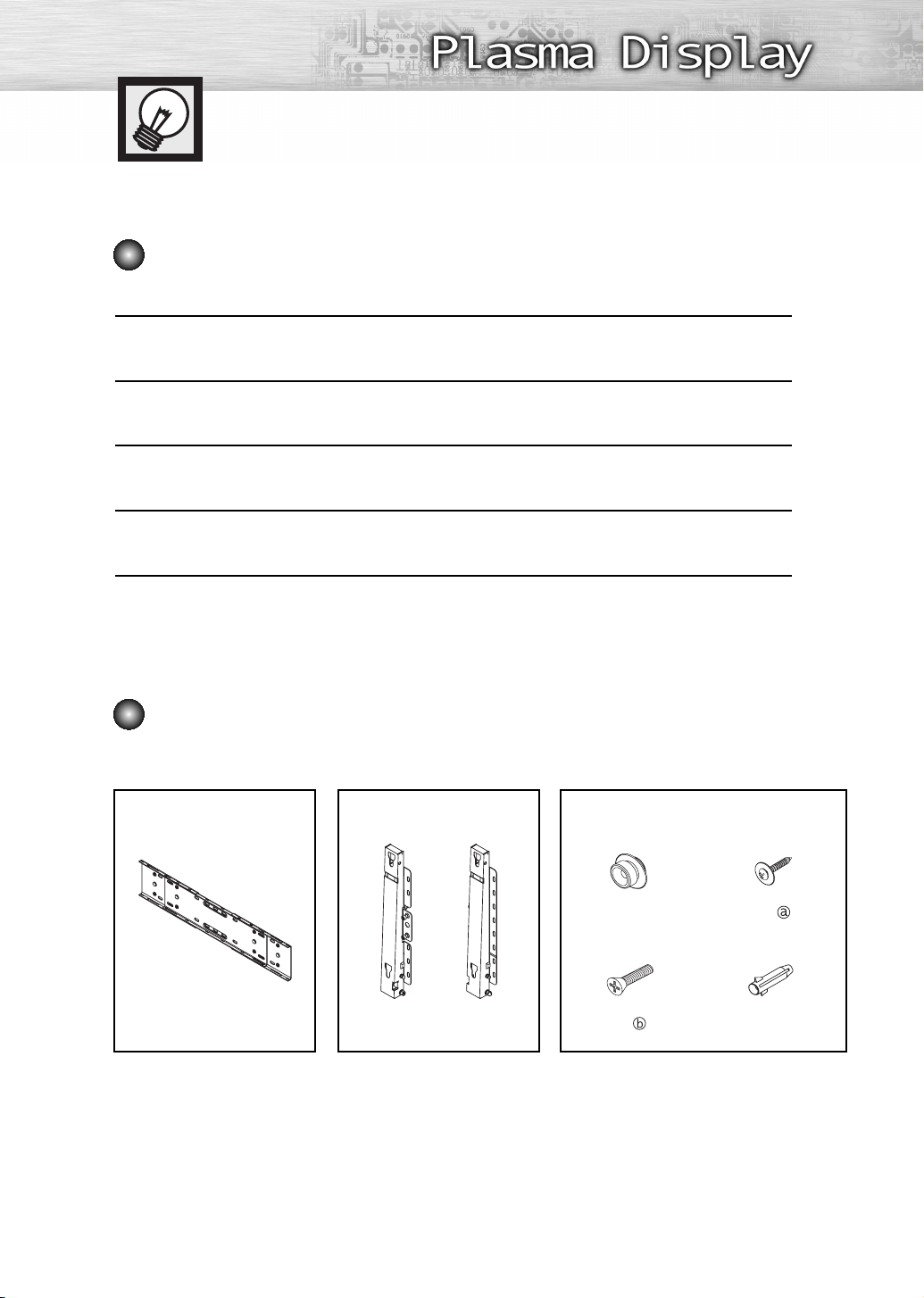
Parts (Wall attachment panel is sold separately. Check with your dealer.)
Only use the components and accessories shipped with the panel.
Wall Bracket Hinge Accessories
Plastic Hanger : 4
Screw : 4
Screw : 11
Anchor : 111 Left : 1 Right : 1
13
Page 14
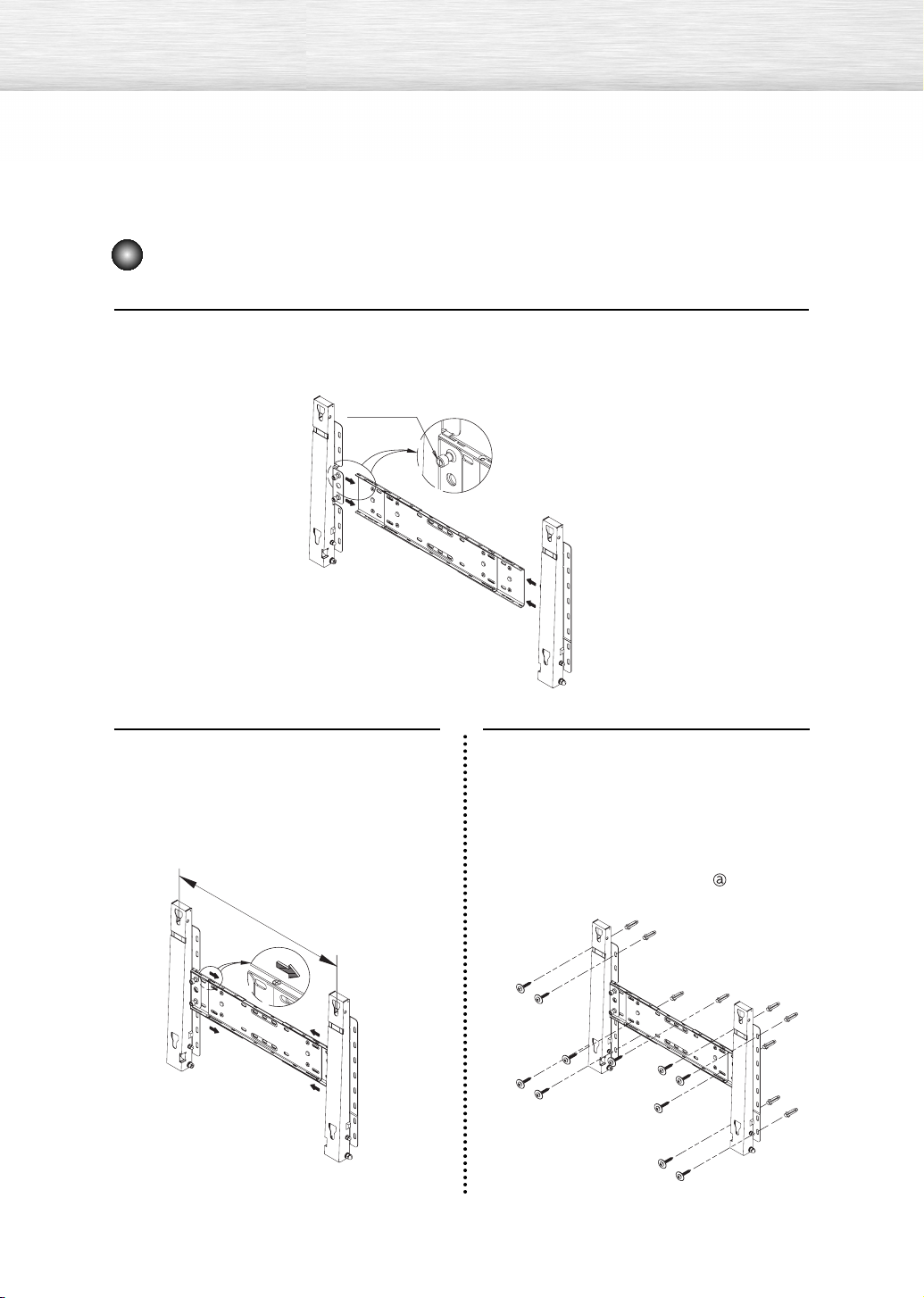
How to assemble the Wall Mount Bracket
Insert and tighten the Captive Screw in the direction of the arrow.
When done, mount the wall bracket on the wall.
1
Captive Screw
Hinge (Left)
There are two hinges
(left and right). Use the
correct one.
Before drilling into the wall, check if the
length between the two locking holes at
2
the back of the product is correct. If the
length is too short or long, loosen all or
some of the 4 screws on the wall
bracket to adjust the length.
Length between the
two locking holes
Wall Bracket
3
Hinge (Right)
Check the installation diagram and
mark the drill points on the wall.
Use the 5.0 mm bit to drill holes deeper
than 35 mm. Fix each anchor in the
corresponding hole. Match each of the
brackets and hinge holes to the
corresponding anchor holes and insert
and tighten the 11 screws .
14
Page 15
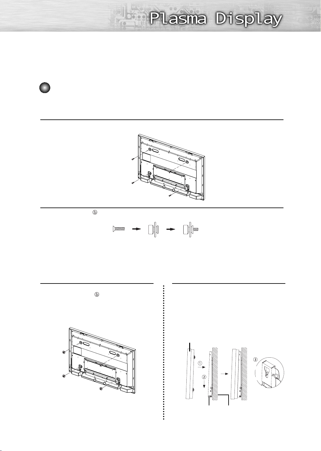
Fixing the TV panel to the wall attachment panel bracket
The shape of the product may vary depending on the model. (The assemblies of the plastic
hanger and the screw are the same)
Remove the 4 screws on the back of the product.
1
Insert the screw into the plastic hanger. (See the figure below)
2
• Mount the product on the wall bracket and make sure it is properly fixed to the left and
right plastic hangers.
• Be careful when installing the product on the bracket as fingers can be caught in the holes.
• Make sure the wall bracket is securely fixed to the wall, or the product may not stay in
place after installation.
Tighten the 4 screws in step 2 (plastic
hanger + screw ) to the rear holes of
3
the product.
Remove safety pin (#) and insert the 4
product holders into the corresponding
4
bracket holes (!). Then place the
product (@) so that it is firmly fixed to
the bracket. Make sure to reinsert and
tighten the safety pin (#) to securely
hold the product to the bracket.
PDP
Wall Bracket Wall
15
Page 16
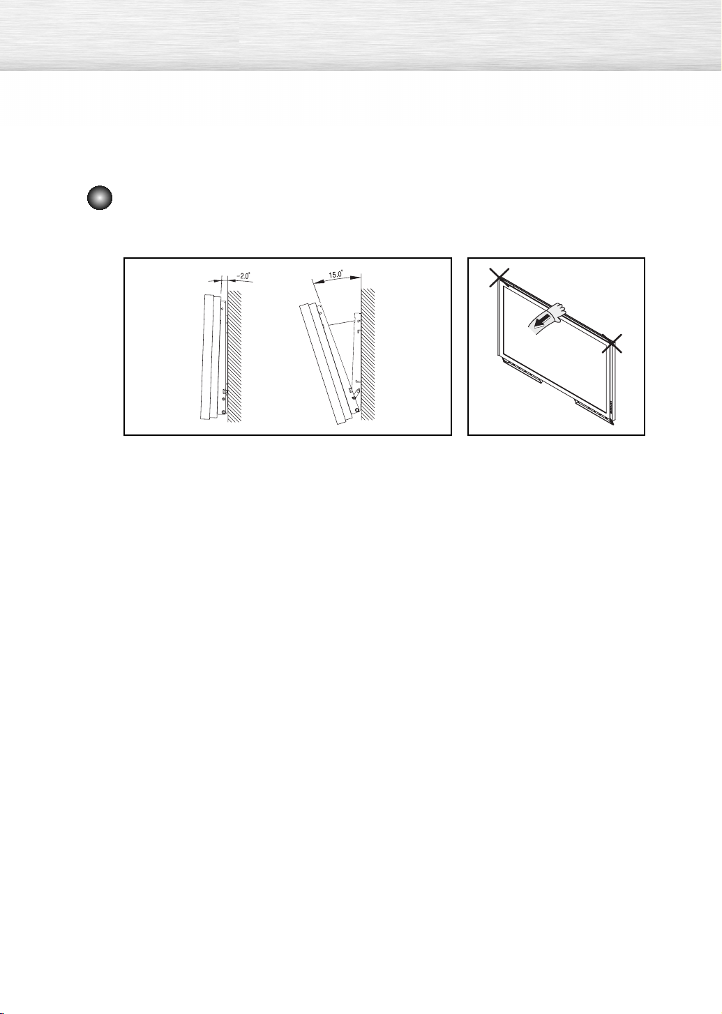
How to Adjust Mounting Angle
Note : Adjust the bracket angle to -2° before installing it on the wall.
Note
1. Fix the product to the wall bracket.
2. Hold the product at the top in the center and pull it
forward (direction of the arrow) to adjust the angle.
(See the figure to the right)
-
3. You can adjust the bracket angle between
2° and 15°.
Make sure to use the top center,
and not the left or the right side of
the product to adjust the angle.
16
Page 17
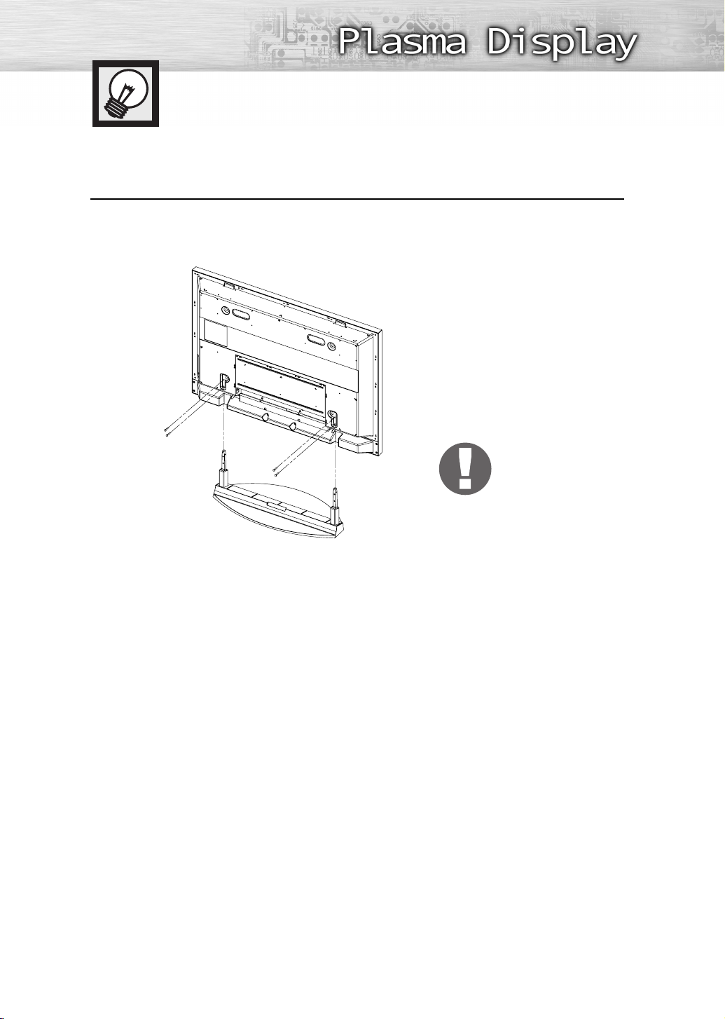
How to assemble the Stand-Base
Using the 4 screws for securing the stand pegs and the monitor, firmly attach the monitor
to the stand pegs. (The exterior of the set may be different than the picture.)
1
Warning
Firmly secure the stand to
the TV before moving it,
as the stand may fall and
could cause serious injury.
Two or more people should carry the TV. Never lay the TV on the floor because of possible damage to the screen.
➤
➤
Always store the TV upright.
17
Page 18

Page 19

PLASMA DISPLAY PANEL
Connections
Connecting VHF and UHF Antennas ..............................................20
Connecting Cable TV....................................................................21
Connecting a VCR........................................................................23
Connecting a Camcorder..............................................................24
Connecting a DVD Player (480i, 480p)..........................................25
Connecting a DTV Receiver (480p, 720p, 1080i) ..........................26
Connecting to HDMI (High Definition Multimedia Interface)
(480p, 720p, 1080i) ..................................................................27
Connecting a Digital TV Set-Top Box (480p, 720p, 1080i) ..............28
Connecting to an Analog Amplifier ................................................29
Page 20

Connecting VHF and UHF Antennas
Antennas with 75-ohm Round Leads
If your antenna looks like this: it has 75-ohm round leads.
Plug the antenna lead into the ANT IN on the TV.
Use an antenna cable. (Sold Separately)
1
20
Page 21
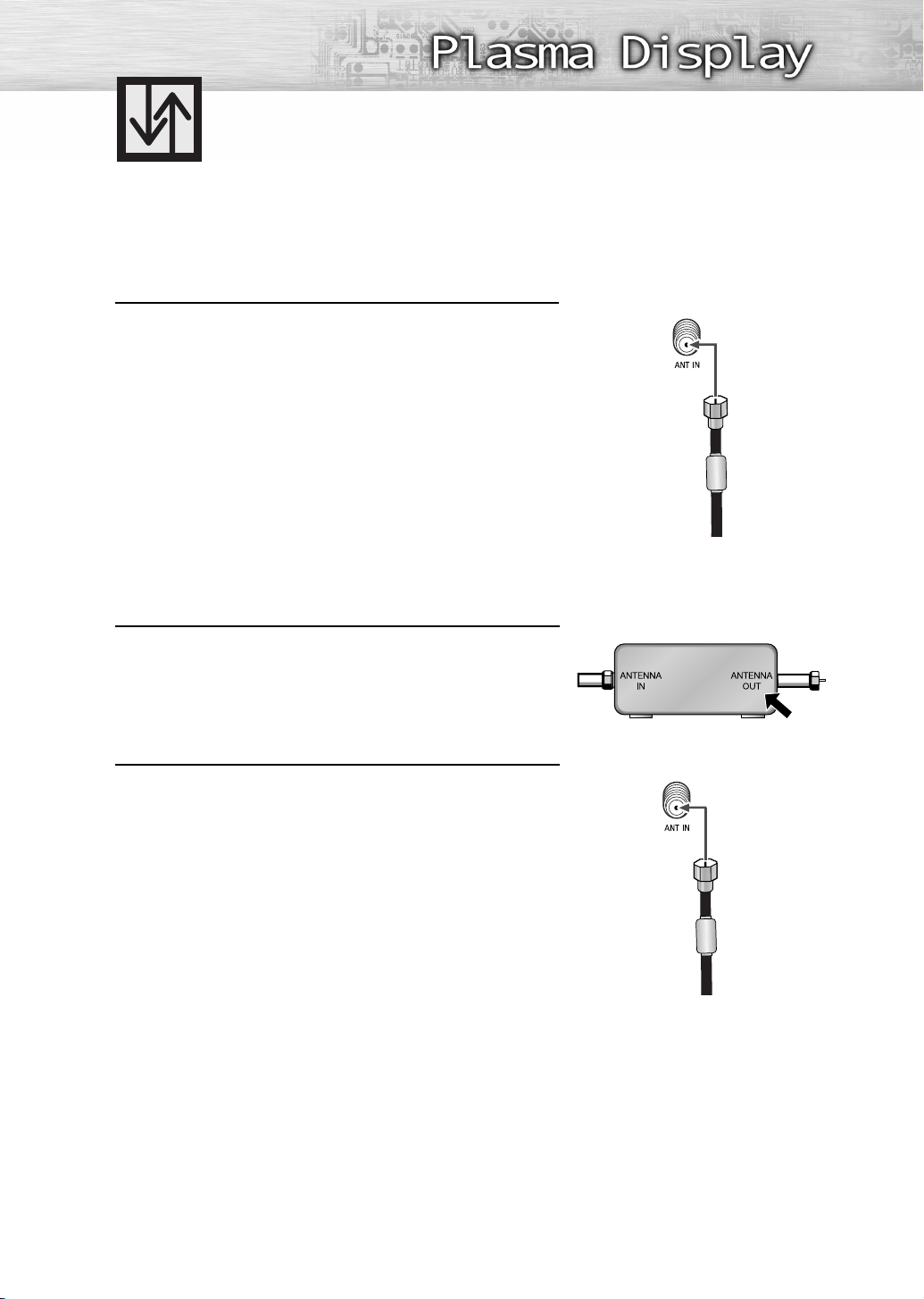
Connecting Cable TV
You can connect different cable systems to your TV, including cable without a Cable box, and cable
with a Cable box that descrambles some or all channels.
Cable without a Cable Box
Plug the incoming cable into the ANT IN on the TV.
Use an antenna cable. (Sold Separately)
1
Cable with a Cable Box that Descrambles All Channels
Find the cable connected to the ANTENNA OUT
terminal on your Cable box. This terminal might be
1
labeled “ANT OUT”, “VHF OUT” or simply “OUT”.
Connect the cable to the ANT IN on the TV.
Use an antenna cable. (Sold Separately)
2
Cable Box
21
Page 22

Cable with a Cable Box that Descrambles Some (But Not All) Channels
To complete this connection you will need a two-way splitter, an RF (A/B) switch, and four coaxial
cables (which you can buy from your Samsung dealer or any electronics store).
Find and disconnect the cable that is
connected to the ANTENNA IN terminal
1
of your Splitter. This terminal might
be labeled “ANT IN”, “VHF IN” or
simply, “IN”. Connect this cable to a
two-way splitter.
Connect a coaxial cable between an
OUT terminal of the splitter and the
2
IN terminal of the Cable box.
Connect a coaxial cable between the
ANTENNA OUT terminal of the Cable
3
box and the B-IN terminal of the RF
(A/B) switch.
Connect another cable between the
other OUT terminal on the splitter and
4
the A–IN terminal on the RF (A/B)
switch.
Connect the last coaxial cable between
the OUT terminal of the RF (A/B)
5
switch and the ANT IN on the TV.
After you've made this connection, set the A/B switch to the “A” position for normal viewing.
Set the A/B switch to the “B” position to view scrambled channels. (When you set the A/B switch to
“B”, you will need to tune your Set-Top Box to the Cable box's output channel, which is usually
channel 3 or 4.)
22
Page 23

Connecting a VCR
Connecting a VCR to the Video or S-Video/Audio jack
TV Rear Panel
VCR
Power cord
Audio cable
Video cable
S-Video cable
How to Connect
Connect the Video/Audio cables between the VIDEO or S-VIDEO/AUDIO input jacks on the
TV and VIDEO or S-VIDEO/AUDIO output jacks on the VCR.
(Note: For better video, use an S-Video cable.)
Note
• Please be sure to match the color coded input terminals and cable jacks.
Videotape Playback:
1. Turn on your TV.
2. Press the SOURCE button to select “Video (AV1 or AV2)” or “S-Video (S-Video1 or S-Video2)”.
3. Turn on your VCR, insert a videotape and press the Play button.
23
Page 24
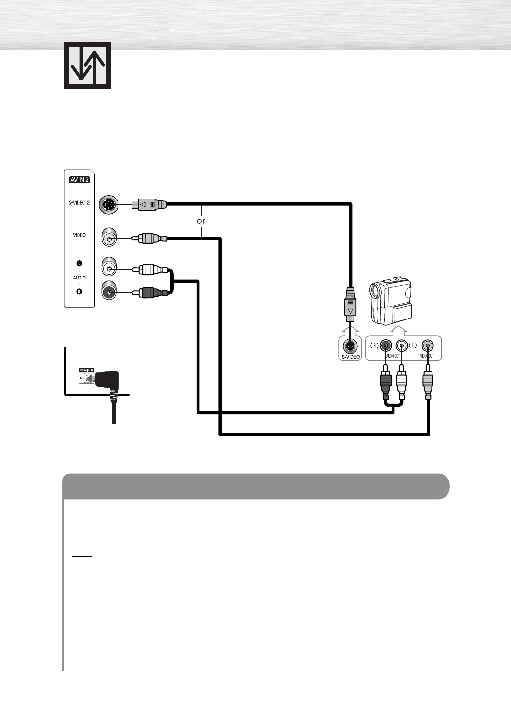
Connecting a Camcorder
Viewing camcorder tapes
Side of the TV
TV Rear Panel
S-Video cable
Camcorder
Audio cable
Power cord
Video cable
How to Connect
Connect a Video/Audio cable between the VIDEO or S-VIDEO/AUDIO input jacks on the TV
and the VIDEO or S-VIDEO/AUDIO output jacks on the camcorder.
(Note: For better video, use an S-VIDEO cable.)
Note
• Please be sure to match the color coded input terminals and cable jacks.
Viewing Tapes
1. Turn on your TV.
2. Press the SOURCE button to select “Video (AV1 or AV2)” or “S-Video (S-Video1 or S-Video2)”.
3. Turn on your camcorder and set it to video mode. (For details, refer to your camcorder
owner’s instructions.)
4. Set the IN/OUT switch on your camcorder to OUT.
5. Insert the tape into the camcorder and press the Play button.
24
Page 25

Connecting a DVD Player (480i, 480p)
Playing DVD
TV Rear Panel
Power cord
DVD Player
Component cable
Audio cable
How to Connect
Connect the Y, PB, PR (COMPONENT1, 2) input jacks on the TV to the Y, PB, PR output jacks
1
on the DVD player using a component cable.
Connect the AUDIO L/R (COMPONENT1, 2) input jacks on the TV to the AUDIO output
2
jacks on the DVD player using a audio cable.
Note
• Please be sure to match the color coded input terminals and cable jacks.
To Play DVD:
1. Turn on your TV.
2. Press the SOURCE button to select “Component 1” or “Component 2”.
3. Turn on your DVD player, insert a DVD disc and press the Play button.
• For an explanation of component video, see your DVD player’s owner’s instructions.
25
Page 26

Connecting a DTV Receiver (480p, 720p, 1080i)
This TV displays the optimum picture in 720p mode.
Watching DTV
TV Rear Panel
Power cord
Component cable
DTV Receiver
Audio cable
HDMI/DVI cable
How to Connect
Connect the cable or antenna to the antenna input jack on the DTV.
1
Connect the Y, P
2
DVI output jacks on the DTV receiver using a component or HDMI/DVI cable.
B, PR (COMPONENT1, 2) or HDMI/DVI input jack on the TV to the Y, PB, PR or
Connect the AUDIO L/R (COMPONENT1, 2 or DVI AUDIO IN) input jacks on the TV with
3
the AUDIO output jacks on the DTV receiver using an audio cable.
Note
• Please be sure to match the color coded input terminals and cable jacks.
To Watch DTV:
1. Turn on your TV.
2. Turn on your DTV receiver.
• For an explanation of component video, see your DTV receiver owner’s instructions.
3. Press the SOURCE button to select “Component1”, “Component2” or “HDMI”.
26
Page 27

Connecting to HDMI (High Definition
Multimedia Interface) (480p, 720p, 1080i)
Watching DTV
TV Rear Panel
Power cord
HDMI cable
DTV Set-Top Box
How to Connect
Connect the cable or antenna to the antenna input jack on the DTV.
1
Connect the HDMI/DVI input jack on the TV with the HDMI output jack on the DTV Set-Top Box
2
using an HDMI cable.
Note
• Please make sure the HDMI source’s power is on before selecting HDMI from the “Source List”
on the TV.
To Watch DTV:
1. Turn on your TV.
2. Turn on your DTV receiver.
• For an explanation of HDMI video, see your DTV receiver owner’s instructions.
3. Press the SOURCE button to select “HDMI”.
27
Page 28

Connecting a Digital TV Set-Top Box
(480p, 720p, 1080i)
By inputting a high-bandwidth digital content protection High-Definition picture source
to the HDMI input jack on the TV, High-Definition pictures can be displayed on the
screen in their digital form.
Connecting to HDMI (High Definition Multimedia Interface)/DVI Compatible
TV Rear Panel
Power cord
HDMI/DVI cable
Audio cable
DTV Set-Top Box
From cable
or Antenna
How to Connect
Connect the DVI AUDIO (L, R) input jacks on the TV with the AUDIO output jacks on the
1
Set-Top Box using an audio cable.
Note
• Use analog stereo audio inputs when using the HDMI input with a device that outputs
DVI instead of HDMI.
Connect the HDMI/DVI input jack on the TV and the DVI output jack on the Set-Top Box
2
using an HDMI/DVI cable.
Note
• The HDMI/DVI IN jack is not compatible with PC.
28
Page 29

TV Rear Panel
Power cord
Connecting to an Analog Amplifier
Audio cable
Analog Amplifier
How to Connect
The “AV OUT (AUDIO L/R)” terminals cannot be used for external speakers.
1
You must hook them up to an amplifier.
When an audio amplifier is connected to the “AV OUT (AUDIO L/R)” terminals:
Decrease the gain (volume) of the audio amplifier, turn the TV’s internal mute on and adjust
the volume level with the volume control of the amplifier.
29
Page 30

Page 31

PLASMA DISPLAY PANEL
Operation
Turning the TV On and Off............................................................32
Plug & Play Feature ......................................................................34
Memorizing the Channels ............................................................37
Adding and Erasing Channels ......................................................39
Setting Up Your Remote Control ....................................................41
Viewing an External Signal Source ................................................43
Page 32

Turning the TV On and Off
Turning the TV On and Off
Press the POWER button on the remote control.
The TV will be turned on and you will be able to use its features.
You can also use the Power button on the front of the TV.
Note
• If your TV isn’t turned on when the power button is pressed:
Press the Mode button to check if the TV mode has been
chosen
Viewing the Menus and Displays
Your TV has a simple, easy-to-use menu system that appears on the TV screen.
This system makes it convenient and fast to use features on the TV.
Your TV also lets you display the status of many of your TV’s features.
().
Viewing the Menus
With the power on, press the MENU button on the
remote control. The main menu appears on the
1
screen. The Input menu is selected.
Press the ▲ or ▼ button to move to items in the menu.
Press the œ/√/ENTER buttons to display,
2
change, or use the selected items.
Press the ENTER button to enter items in the menu.
On screen menus disappear from the screen
automatically after about two minutes or you can press
the EXIT button on your remote control to exit the menu.
TV
Source List : TV
Edit Name
Move Enter Exit
Input
√
√
32
Page 33

Displaying Status Information
Press the INFO button on the remote control.
The TV will display the Picture
mode
, Sound
mode
SRS TSXT, and Current Time.
Note
• The INFO window automatically disappears after
a few seconds. Press the INFO button once to
manually close the window.
, MTS,
Air 28
Mono
Picture : Dynamic
Sound : Custom
MTS : Stereo
SRS TSXT : Off
12 : 00 am
33
Page 34

Plug & Play Feature
When the TV is initially powered On, basic customer settings proceed automatically and
subsequently: Setting the language, checking the antenna input, memorizing the
channels, and setting the time.
Note
• The Plug & Play function operates after plugging in the TV for the first time.
If the television is in Standby mode, press the POWER
button on the remote control.
1
The message Start Plug & Play is displayed.
Press the ENTER button to select OK.
The Language menu is displayed.
Note
• The Language menu will automatically appear
after several seconds, even if the ENTER button is
not pressed.
Select the appropriate language by pressing the
▲ or ▼ button.
2
Press the ENTER button to confirm your choice.
The message Check antenna input is displayed.
Note
• The message Check antenna input will
automatically appear after several seconds, even
if the ENTER button is not pressed.
Press the ENTER button to select OK.
The menu to select signal source is displayed.
3
Plug & Play
Start Plug & Play
Plug & Play
Language
Plug & Play
Check antenna input.
OK
Enter Exit
English
Français
Español
Português
Enter SkipMove
OK
34
Select the correct signal source (Air, STD, HRC and IRC)
by pressing the
4
ENTER button.
▲ or ▼
button, then press the
Air/Cable
Enter Skip
Plug & Play
Air
STD
HRC
IRC
Enter SkipMove
Page 35

To start the channel search, press the ENTER
button.
5
Plug & Play
Air 3
Notes
• The search will end automatically. Channels are
sorted and stored in an order which reflects their
position in the frequency range (with lowest first
and highest last).
When it has finished, the Clock Set menu is
displayed.
• To stop the search before it has finished or return
to normal viewing, press the MENU button.
Press the ENTER button.
Press the
6
or am/pm.
Set the Hour, Minute, or am/pm by pressing the
▲ or ▼
Press the ENTER button.
œ or √
button.
button to move to the hour, minute,
Note
• You can set the Hour and Minute directly by
pressing the number buttons on the remote control.
When it has finished, the message “Enjoy your
watching” is displayed, and the channels which
7
have been stored can be viewed.
Start
Enter Skip
Plug & Play
Air 56
Stop
Enter Skip
Plug & Play
Clock Set 12 : 00 am
EnterAdjustMove Skip
Enjoy your watching.
OK
35
Page 36

Plug & Play Feature
To reset this feature....
(continued)
Press the MENU button. Press the ▲ or ▼ button to select
“Setup”, then press the ENTER button.
1
Press the ENTER button to select “Plug & Play”.
2
For further details on setting up options, refer to the
previous page.
3
Note
• Plug and Play can only be accessed in the TV mode.
TV
Plug & Play
Language : English
Time
V-Chip
Caption
Blue Screen : Off
Melody : Off
†
More
Start Plug & Play
Setup
√
√
√
√
√
√
√
Move Enter Return
Plug & Play
OK
Enter Return
36
Page 37

Memorizing the Channels
Your TV can memorize and store all of the available channels for both “off-air” (antenna) and cable
channels. After the available channels are memorized, use the CH and CH buttons to scan
through the channels. This eliminates the need to change channels by entering the channel digits.
There are three steps for memorizing channels: selecting a broadcast source, memorizing the
channels (automatic) and adding and deleting channels (manual).
Selecting a broadcast source
Before your television can begin memorizing the available channels, you must specify the type of signal
source that is connected to the TV (i.e., an antenna or a cable system).
Press the MENU button. Press the ▲ or ▼ button to select
“Channel”, then press the ENTER button.
1
Press the ENTER button to select “Air/Cable”.
2
Press the ▲ or ▼ button to select “Air”, “STD”, “HRC”
or “IRC”, then press the ENTER button.
3
• If you are connected to an antenna, leave “Air”
displayed. If you connected cable, press the ▲ or ▼
button to display the type of cable system: “STD”,
“HRC” or “IRC”.
(If you are not sure which type of cable system you
have, contact your cable company).
TV
Air/Cable : Air
Auto Program
Add/Delete
Fine Tune
LNA : Off
TV
Air/Cable : Air
Auto Program
Add/Delete
Fine Tune
LNA : Off
TV
Air/Cable : Air
Auto Program
Add/Delete
Fine Tune
LNA : Off
Channel
√
√
√
√
√
Move Enter Return
Channel
Air
STD
HRC
IRC
Move Enter Return
Channel
Air
STD
HRC
IRC
Move Enter Return
Press the EXIT button to exit.
4
Note
• STD, HRC and IRC identify various types of cable TV systems. Contact your local cable company to
identify the type of cable system that exists in your particular area. At this point the signal source
has been selected. Proceed to “Storing Channels in Memory” (Next page).
37
Page 38

Storing Channels in Memory
First, select the correct signal source (Air, STD, HRC
and IRC). See steps on previous page.
1
Press the MENU button. Press the
▲ or ▼
select “Channel”, then press the ENTER button.
Press the ▲ or ▼ button to select “Auto Program”,
then press the ENTER button.
2
Quick way to access the Automatic Channel Setting: Just press the
➤
➤
“AUTO PROG.” button under the cover of the remote control.
Press the ENTER button.
The TV will begin memorizing all of the available
3
channels.
After all the available channels are stored, the Auto
program menu reappears.
Press the ENTER button to stop.
button to
TV
Air/Cable : Air
Auto Program
Add/Delete
Fine Tune
LNA : Off
TV
Air/Cable : Air
Auto Program
Add/Delete
Fine Tune
LNA : Off
Channel
Move Enter Return
Channel
Move Enter Return
Auto Program
Air 3
Start
Enter
Return
√
√
√
√
√
√
√
√
√
√
Press the EXIT button to exit.
4
Notes
• All available analog channels are automatically stored in
memory.
• It takes approximately 3 to 10 minutes to memorize
channels.
38
Page 39

Adding and Erasing Channels
To add channels that were not memorized (or to delete unwanted channels from memory):
Press the MENU button.
Press the ▲ or ▼ button to select “Channel”, then
1
press the ENTER button.
Quick way to access the Adding and Erasing Channels : Just press the
➤
➤
“ADD/DEL” button under the cover of the remote control.
Press the ▲ or ▼ button to select “Add/Delete”, then
press the ENTER button.
2
Repeatedly pressing the ENTER button will alternate
between add channel and delete channel.
3
Press the CH or CH button to switch to the
appropriate channel, then repeat above.
Press the EXIT button to exit.
TV
Air/Cable : Air
Auto Program
Add/Delete
Fine Tune
LNA : Off
TV
Air/Cable : Air
Auto Program
Add/Delete
Fine Tune
LNA : Off
Channel
√
√
√
√
√
Move Enter Return
Channel
√
√
√
√
√
Move Enter Return
Add/Delete
Air 3 Not in Memory
Add
EnterChange Return
Add/Delete
Air 3 In Memory
Delete
EnterChange Return
39
Page 40

Changing Channels
Using the Channel Buttons
Press the CH or CH button to change channels.
When you press the CH or CH button, the TV changes channels
in sequence. You will see all the channels that the TV has memorized.
(The TV must have memorized at least three channels.)
You will not see channels that were either erased or not memorized.
Directly Accessing Channels
Press the number buttons to go directly to a channel. For example, to select
channel 27, press “2” then “7”.
When you use the number buttons, you can directly select channels that were
either erased or not memorized. To select a channel over 100, press the
+100 button. (For channel “112”, press the +100 button, then “1”, then “2”.
To change to single-digit channels (0~9) faster, press “0” before the single
digit. (For channel “4” press “0”, then “4”).
Note
• For quick channel change, press the number buttons and, then press
ENTER button.
Using the PRE-CH button to select the previous channel
Press the PRE-CH button. The TV will switch to the last channel viewed.
To quickly switch between two channels that are far apart, tune to one
channel, then use the number button to select the second channel.
Then, use the PRE-CH button to quickly alternate between them.
Adjusting the Volume
Using the Volume Buttons
Press the VOL or VOL button to increase or decrease the volume.
Using Mute
Using the MUTE Button
At any time, you can temporarily cut off the sound using the MUTE button.
Press the MUTE button and the sound cuts off. The word “Mute” will
appear in the lower-left corner of the screen.
1
To turn mute off, press the MUTE button again, or simply press the
VOL or VOL button.
2
40
Mute
Page 41

Setting Up Your Remote Control
Your TV comes equipped with a universal remote control. In addition to controlling the TV, the universal
remote control can also operate a VCR, Cable box, DVD, and some Samsung Set-top boxes (even if your
VCR, Cable box and DVD are made by manufacturers other than Samsung).
Note :
Setting Up the Remote to Operate Your VCR, Cable box or DVD player
1
2
3
●
The remote control might not be compatible with all DVD Players, VCRs, Cable boxes,
and Set-Top Boxes.
Turn off your VCR (or Cable box, DVD player).
Press the MODE button. The Mode is changed whenever
MODE button is pressed.
Press the SET button on your TV's remote control.
Using the number buttons on your remote control, enter
three digits of the VCR (or Cable box, DVD player) code
4
listed on page 42 of this manual for your brand of VCR (or
Cable box, DVD). Make sure you enter three digits of the
code, even if the first digit is a “0”. (If more than one code
is listed, try the first one.)
Press the POWER button on the remote control. Your VCR
(or Cable box, DVD) should turn on if your remote is set up
5
correctly. If your VCR (or Cable box, DVD) does not turn on
after setup, repeat steps 2, 3, and 4, but try one of the
other codes listed for your brand of VCR (or Cable box,
DVD). If no other codes are listed, try each code, 000
through 089 (or Cable box: 000 through 077, DVD player:
000 through 008).
Note
• When your remote control is in “VCR”, “CABLE”, or “DVD” mode, the VCR control buttons (STOP,
REW, PLAY/PAUSE, and FF) still operate your VCR.
41
Page 42

Remote Control Codes
VCR Codes
Cable Box Codes
DVD Codes
42
Page 43

Viewing an External Signal Source
Use the remote control to switch between viewing signals from connected equipment, such as VCR,
DVD, Set-Top Box, and the TV source (broadcast or cable).
Setting the Signal Source
Press the MENU button.
Press the ENTER button to select “Input”.
1
Quick way to access viewing an external signal source :
➤
➤
Just press the “SOURCE” button on the remote control.
Press the ENTER button to select “Source List”.
2
Press the ▲ or ▼ button to select signal source, then
press the ENTER button.
3
Note
• Only connected devices can be selected.
TV
TV
TV
Input
Source List : TV
Edit Name
Move Enter Return
Source List
TV
AV1 :
AV2 :
S-Video1 :
S-Video2 :
Component1 :
Component2 :
†
More
Move Enter Return
Source List
…
More
PC :
HDMI :
Move Enter Return
√
√
----
----
----
----
----
----
----
----
Press the EXIT button to exit.
4
Notes
• When you connect equipment to the TV, you can choose
between the following sets of jacks: AV1, S-VIDEO1,
COMPONENT 1, COMPONENT 2, PC, or HDMI on the
TV’s rear panel and AV2 or S-VIDEO2 on the TV’s side panel.
• HDMI input can only be selected when the external device
is turned on and connected via HDMI.
43
Page 44

Assigning Names to External input mode
Press the MENU button.
Press the ENTER button to select “Input”.
1
Press the ▲ or ▼ button to select “Edit Name”, then
press the ENTER button.
2
Press the ENTER button.
Press the ▲ or ▼ button to select external device,
3
then press the ENTER button.
• You can select the VCR, DVD, D-VHS, Cable STB,
HD STB, Satellite STB, AV Receiver, DVD Receiver,
Game, Camcorder, DVD Combo, DHR, or PC.
• Set other signal sources (AV2, S-Video1, S-Video2,
Component1, Component2, PC, or HDMI) using the
same method as listed above.
TV
TV
TV
Input
Source List : TV
Edit Name
Move Enter Return
Edit Name
AV1 :
AV2 :
S-Video1 :
S-Video2 :
Component1 :
Component2 :
PC :
HDMI :
Move Enter Return
Edit Name
AV1 :
AV2 :
S-Video1 :
S-Video2 :
Component1 :
Component2 :
PC :
HDMI :
Move Enter Return
----
----
----
----
----
----
----
----
----
----
----
----
----
----
----
----
----
VCR
DVD
D-VHS
Cable STB
†
√
√
√
√
√
√
√
√
√
√
44
Press the EXIT button to exit.
4
Page 45

PLASMA DISPLAY PANEL
Picture Control
Changing the Picture Standard ......................................................46
Customizing the Picture Settings ....................................................47
Viewing the DNIe Demonstration ..................................................49
Changing the Screen Size ............................................................50
Viewing the Picture-in-Picture..........................................................52
Setting the My Color Control Mode................................................58
Page 46

Changing the Picture Standard
You can select the type of picture which best corresponds to your viewing requirements.
Press the MENU button. Press the ▲ or ▼ button to select
“Picture”, then press the ENTER button.
1
Quick way to access the picture setting: Just press the “P.MODE”
➤
➤
button on the remote control.
Press the ENTER button again to select “Mode”.
2
Press the ENTER button.
Press the ▲ or ▼ button to select the desired picture
3
mode (Dynamic, Standard, Movie, Custom), then press
the ENTER button.
TV
Mode : Dynamic
Size : Wide
Digital NR : On
DNIe Demo : Off
My Color Control
Energy Saving : Standard
PIP
TV
Mode : Dynamic
Contrast 100
Brightness 50
Sharpness 75
Color 55
Tint G 50 R 50
Color Tone : Cool2
Reset
TV
Mode : Dynamic
Contrast 100
Brightness 50
Sharpness 75
Color 55
Tint G 50 R 50
Color Tone : Cool2
Reset
Picture
Move Enter Return
Mode
Move Enter Return
Mode
Move Enter Return
√
√
√
√
√
√
√
√
√
Dynamic
Standard
Movie
Custom
Press the EXIT button to exit.
4
• Choose Dynamic for viewing the TV during the day or when
there is bright light in the room.
• Choose Standard for the standard factory settings.
• Choose Movie when viewing the movie.
• Choose Custom if you want to adjust the settings according
to personal preference
(see “Customizing the Picture Settings”, page 47).
46
Page 47

Customizing the Picture Settings
You can use the on-screen menus to change the “Contrast”, “Brightness”, “Sharpness”, “Color”,
“Tint”, and “Color Tone” according to personal preference. You can select “Standard” which
automatically recalls your personalized picture settings.
Press the MENU button. Press the ▲ or ▼ button to select
“Picture”, then press the ENTER button.
1
Quick way to access the picture setting: Just press the “P.MODE”
➤
➤
button on the remote control.
Press the ENTER button again to select “Mode”.
2
Press the ENTER button.
Press the ▲ or ▼ button to select the desired picture
3
mode (Dynamic, Standard, Movie, Custom), then press
the ENTER button.
TV
Mode : Dynamic
Size : Wide
Digital NR : On
DNIe Demo : Off
My Color Control
Energy Saving : Standard
PIP
TV
Mode : Dynamic
Contrast 100
Brightness 50
Sharpness 75
Color 55
Tint G 50 R 50
Color Tone : Cool2
Reset
TV
Mode : Dynamic
Contrast 100
Brightness 50
Sharpness 75
Color 55
Tint G 50 R 50
Color Tone : Cool2
Reset
Picture
Move Enter Return
Move Enter Return
Move Enter Return
√
√
√
√
√
√
√
Mode
√
√
Mode
Dynamic
Standard
Movie
Custom
Press the ▲ or ▼ button to select a particular option
(Contrast, Brightness, Sharpness, Color, or Tint), then
4
press the ENTER button.
Press the œ or √ button to decrease or increase the
value of a particular item.
• You can also select these options (Contrast,
Brightness, Sharpness, Color, or Tint) by pressing
the ▲ or ▼ button.
Notes
• “Tint” doesn’t operate in PC, HDMI or any Component modes.
• The Tint cannot be adjusted while watching Digital TV.
TV
Mode : Custom
Contrast 90
Brightness 50
Sharpness 75
Color 50
Tint G 50 R 50
Color Tone : Normal
Reset
Move Enter Return
Contrast
Mode
√
√
90
47
Page 48

Press the ENTER button to return to “Mode”.
Press the ▲ or ▼ button to select “Color Tone”, then
5
press the ENTER button.
TV
Mode : Custom
Contrast 90
Brightness 50
Sharpness 75
Color 50
Tint G 50 R 50
Color Tone : Normal
Reset
Mode
Move Enter Return
√
√
Press the ▲ or ▼ button to select a particular option
(Cool2, Cool1, Normal, Warm1, or Warm2), then press
6
the ENTER button.
Resetting the Picture Settings to the Factory Defaults
To return the factory defaults, select “Reset” by pressing
the ▲ or ▼ button.
7
Press the ENTER button.
Press the EXIT button to exit.
• The previously adjusted settings will be reset to the
factory defaults.
TV
Mode : Custom
Contrast 90
Brightness 50
Sharpness 75
Color 50
Tint G 50 R 50
Color Tone : Normal
Reset
TV
Mode : Custom
Contrast 90
Brightness 50
Sharpness 75
Color 50
Tint G 50 R 50
Color Tone : Normal
Reset
Mode
Move Enter Return
Mode
Move Enter Return
Cool2
Cool1
Normal
Warm1
Warm2
√
√
48
Page 49

Viewing the DNIe Demonstration
This TV includes the DNIe function so as to provide a high visual quality.
If you set DNIe Demo to On, you can view the applied DNIe and normal pictures on the screen,
for demonstration purposes. Using this function, you can view the difference in the visual quality.
Press the MENU button. Press the ▲ or ▼ button to select
“Picture”, then press the ENTER button.
1
Press the ▲ or ▼ button to select “DNIe Demo”, then
press the ENTER button.
2
Press the ▲ or ▼ button to select “Off” or “On”, then
press the ENTER button.
3
• Off : Switches off the DNIe Demo mode.
• On : Switches on the DNIe Demo mode.
TV
Mode : Dynamic
Size : Wide
Digital NR : On
DNIe Demo : Off
My Color Control
Energy Saving : Standard
PIP
TV
Mode : Dynamic
Size : Wide
Digital NR : On
DNIe Demo : Off
My Color Control
Energy Saving : Standard
PIP
TV
Mode : Dynamic
Size : Wide
Digital NR : On
DNIe Demo : Off
My Color Control
Energy Saving : Standard
PIP
Picture
√
√
√
√
√
√
√
Move Enter Return
Picture
Off
On
Move Enter Return
Picture
Off
On
Move Enter Return
Press the EXIT button to exit.
4
DNIe Off DNIe On
Note
• DNIeTM(Digital Natural Image engine)
This feature brings you a more detailed image with 3D noise reduction and detail,
contrast and white enhancement.
DNIe Demo
49
Page 50

Changing the Screen Size
Screen size selection depends on the type of video input.
Press the MENU button. Press the ▲ or ▼ button to
select “Picture”, then press the ENTER button.
1
Quick way to change the Screen size: Simply press the P.SIZE button on
➤
➤
the remote control.
Press the ▲ or ▼ button to select “Size”, then press the
ENTER button.
2
Press the ▲ or ▼ button to select the screen size you
want, then press the ENTER button.
3
Press the EXIT button to exit.
4
TV
Mode : Dynamic
Size : Wide
Digital NR : On
DNIe Demo : Off
My Color Control
Energy Saving : Standard
PIP
Move Enter Return
TV
Mode : Dynamic
Size : Wide
Digital NR : On
DNIe Demo : Off
My Color Control
Energy Saving : Standard
PIP
Move Enter Return
TV
Wide
Wide 4:3
Panorama
Zoom
4:3
Move Enter Return
Picture
√
√
√
√
√
√
√
Picture
√
√
√
√
√
√
√
Size
Notes
•
Supported screen resolution modes may differ depending on the
model of the product.
•
If you watch a still image or the 4:3 (Normal) mode for a long
time (over 2 hours), an image may be burned onto the screen.
•
View the TV in Wide (16:9) or Panorama mode as much as
possible.
• Wide : Sets the picture to 16:9 wide mode.
• Wide 4:3 : Magnify the size of the picture more than 4:3.
Move the screen up/down using the ▲ or ▼
button after selecting the by pressing the
or ENTER button.
• Panorama : Sets the picture to the wide aspect ratio of a
panoramic picture.
• Zoom : Magnifies the size of the picture on the screen.
(For more information, refer to the following page.)
• 4:3 : Sets the picture to 4:3 normal mode.
50
√
Page 51

When you press the P.SIZE button on the remote control, the TV’s screen mode should
appear in sequence. The screen displays in this order: Wide, Wide 4:3, Panorama, Zoom, 4:3.
Wide
Sets the picture to 16:9 wide mode
Wide
.
Panorama
Converts regular 4:3 aspect ratio screen to
wide screen.
Panorama Zoom
4:3
Sets the picture to 4:3 normal mode.
4:3
Notes
• In TV, VIDEO, S-VIDEO, and COMPONENT(480i) modes, all screen modes can be selected.
➞
(Wide
• In COMPONENT(480p, 720p, 1080i) mode, only Wide, Wide 4:3, Zoom, 4;3 modes can be selected.
• In PC, HDMI modes, only Wide & 4:3 modes can be selected.
• If you change the picture size when PIP is On, PIP will automatically be turned Off.
Wide 4:3 ➞Panorama ➞Zoom ➞4:3).
Wide 4:3
Magnify the size of the picture more than 4:3.
Wide 4:3
Zoom
Magnifies the size of the picture on the
screen.
Positioning and Sizing the screen using Zoom
• Resizing the screen using the Zoom enables
the positioning and sizing of the screen to
up/down direction using the ▲ or ▼
button as well as the screen size.
• Move the screen up/down using the ▲ or
▼ button after selecting the by pressing
the œ or √ button.
• Resize the screen vertically using the ▲ or
▼ button after selecting the by pressing
the œ or √ button.
(Pressing the ▲ button extends it upward
and pressing the ▼ button extends it
downward.)
• Screen enlargement operates only in TV/
AV1,2/S-Video1,2/Component1,2 input
modes.
• PC mode prevent the screen enlargement
function.
51
Page 52

Viewing the Picture-in-Picture
Selecting the PIP Screen
Press the MENU button. Press the ▲ or ▼ button to select
“Picture”, then press the ENTER button.
1
Quick way to access the PIP mode: Simply press the “PIP” button on the
➤
➤
remote control.
Press the ▲ or ▼ button to select “PIP”, then press the
ENTER button.
2
Press the ENTER button, then press the ▲ or ▼
button to select “On”. The PIP image will appear in
3
the corner of the screen.
• Pressing the ▲ or ▼ button will alternate between
“On” and “Off”.
Note
• If the PIP On/Off does not function, check if the
V-Chip Lock (refer to page 99) is On. PIP does
not function when the V-Chip Lock is set to On.
Change the setting to Off and try it again.
Press the EXIT button to exit.
4
TV
Mode : Dynamic
Size : Wide
Digital NR : On
DNIe Demo : Off
My Color Control
Energy Saving : Standard
PIP
Move
TV
PIP : Off
Source : TV
Swap
Size :
Position :
Channel : Air 3
Move
TV
PIP : On
Source : TV
Swap
Size :
Position :
Channel : Air 3
Move Enter Return
Picture
√
√
√
√
√
√
√
Enter Return
PIP
√
√
√
√
√
Enter Return
PIP
√
√
√
√
√
PIP Settings
Main screen
PIP screen
TV
AV1
AV2
S-Video1
S-Video2
Component1
Component2
PC
HDMI
TV AV1 AV2 Component1 Component2 PC HDMI
O
O
O
X
O
O
O
O
O
O
X
X
X
X
X
X
X
X
S-Video1
O
O
X
O
X
X
X
X
X
S-Video2
O
X
O
X
O
X
X
X
X
O
O
X
O
X
X
X
X
X
O
O
O
O
O
X
X
X
X
O : PIP and swap operate
X : PIP doesn’t operate
O
O
O
O
O
X
X
X
X
O
O
O
O
O
X
X
X
X
Note
• This TV has only one tuner and does not allow you to watch one TV channel in the main screen and
another channel in the PIP screen.
52
O
O
O
O
O
X
X
X
X
Page 53

Selecting an External Signal
You can use PIP to view a signal from an external source, such as a VCR.
Press the MENU button. Press the ▲ or ▼ button to select
“Picture”, then press the ENTER button.
1
Press the ▲ or ▼ button to select “PIP”, then press the
ENTER button.
2
Press the ▲ or ▼ button to select “Source”, then press
the ENTER button.
3
TV
Mode : Dynamic
Size : Wide
Digital NR : On
DNIe Demo : Off
My Color Control
Energy Saving : Standard
PIP
TV
PIP : On
Source : TV
Swap
Size :
Position :
Channel : Air 3
TV
PIP : On
Source : TV
Swap
Size :
Position :
Channel : Air 3
Picture
√
√
√
√
√
√
√
Move Enter Return
PIP
√
√
√
√
√
Move Enter Return
PIP
TV
AV1
AV2
S-Video1
S-Video2
Move Enter Return
Press the ▲ or ▼ button to cycle through all of the
available signal sources: “TV”, “AV1”, “AV2”,
4
“S-Video1”, or “S-Video2”.
Note
• The signal from these inputs will not appear if you
have not connected any equipment to the TV's
respective input jacks.
Press the EXIT button to exit.
5
Notes
• The same source cannot be selected on both the main and sub screens.
• PC is not available in PIP picture.
53
Page 54

Swapping the Contents of the PIP and Main Image
Press the MENU button. Press the ▲ or ▼ button to select
“Picture”, then press the ENTER button.
1
Quick way to change the size of the PIP window : Just press the “SWAP”
➤
➤
button under the cover of the remote control.
Press the ▲ or ▼ button to select “PIP”, then press the
ENTER button.
2
Press the ▲ or ▼ button to select “Swap”, then press the
ENTER button.
3
• The image in the PIP window will appear on the
main screen, and vice versa. (Refer to page 52)
Note
If main picture is in PC, Component1, Component2, or
•
HDMI mode, Swap is not available.
TV
Mode : Dynamic
Size : Wide
Digital NR : On
DNIe Demo : Off
My Color Control
Energy Saving : Standard
PIP
Move Enter Return
TV
PIP : On
Source : TV
Swap
Size :
Position :
Channel : Air 3
Move Enter Return
TV
PIP : On
Source : TV
Swap
Size :
Position :
Channel : Air 3
Move Enter Return
Picture
√
√
√
√
√
√
√
PIP
√
√
√
√
√
PIP
√
√
√
√
√
54
Press the EXIT button to exit.
4
Page 55

Changing the Size of the PIP Window
Press the MENU button. Press the ▲ or ▼ button to select
“Picture”, then press the ENTER button.
1
Quick way to change the size of the PIP window : Just press the “SIZE”
➤
➤
button under the cover of the remote control.
Press the ▲ or ▼ button to select “PIP”, then press the
ENTER button.
2
Press the ▲ or ▼ button to select “Size”, then press the
ENTER button.
3
TV
Mode : Dynamic
Size : Wide
Digital NR : On
DNIe Demo : Off
My Color Control
Energy Saving : Standard
PIP
TV
PIP : On
Source : TV
Swap
Size :
Position :
Channel : Air 3
TV
PIP : On
Source : TV
Swap
Size :
Position :
Channel : Air 3
Picture
√
√
√
√
√
√
√
Move Enter Return
PIP
√
√
√
√
√
Move Enter Return
PIP
Move Enter Return
Press the ▲ or ▼ button to select option you want, then
press the ENTER button.
4
Press the EXIT button to exit.
5
TV
PIP : On
Source : TV
Swap
Size :
Position :
Channel : Air 3
PIP
Move Enter Return
55
Page 56

Changing the Location of the PIP Image
Press the MENU button. Press the ▲ or ▼ button to select
“Picture”, then press the ENTER button.
1
Press the ▲ or ▼ button to select “PIP”, then press the
ENTER button.
2
Press the ▲ or ▼ button to select “Position”, then press
the ENTER button.
3
TV
Mode : Dynamic
Size : Wide
Digital NR : On
DNIe Demo : Off
My Color Control
Energy Saving : Standard
PIP
Move Enter Return
TV
PIP : On
Source : TV
Swap
Size :
Position :
Channel : Air 3
Move Enter Return
TV
PIP : On
Source : TV
Swap
Size :
Position :
Channel : Air 3
Move Enter Return
Picture
√
√
√
√
√
√
√
PIP
√
√
√
√
√
PIP
Press the ▲ or ▼ button to select the PIP position you
want, then press the ENTER button.
4
TV
PIP : On
Source : TV
Swap
Size :
Position :
Channel : Air 3
Press the EXIT button to exit.
5
Note
• In Double Window ( ) and Double Wide ( ) modes, Position cannot be selected.
56
PIP
Move Enter Return
Page 57

Changing the PIP Channel
Press the MENU button. Press the ▲ or ▼ button to select
“Picture”, then press the ENTER button.
1
Quick way to change the PIP channel: Just press the “CH “ or
➤
➤
“CH ” button under the cover of the remote control.
Press the ▲ or ▼ button to select “PIP”, then press the
ENTER button.
2
Press the ▲ or ▼ button to select “Channel”, then press
the ENTER button.
3
TV
Mode : Dynamic
Size : Wide
Digital NR : On
DNIe Demo : Off
My Color Control
Energy Saving : Standard
PIP
TV
PIP : On
Source : TV
Swap
Size :
Position :
Channel : Air 3
TV
PIP : On
Source : TV
Swap
Size :
Position :
Channel : Air 3
Picture
Move Enter Return
PIP
Move Enter Return
PIP
▲
Air 3
▲
Adjust Enter Return
√
√
√
√
√
√
√
√
√
√
√
√
Press the ▲ or ▼ button to change the channel that
appears in the PIP window.
4
Press the EXIT button to exit.
5
TV
PIP : On
Source : TV
Swap
Size :
Position :
Channel : Air 3
PIP
▲
Air 10
▲
Adjust Enter Return
57
Page 58

Setting the My Color Control Mode
My Color Control allows you to adjust colors according to your preference, by adjusting skin, sky,
and grass tones using the predefined settings (Standard, Custom, Blue, Green, Pink) without
affecting other colors on the screen.
Using the My Color Control Function in the Easy Control Menu
Skin, sky and grass tones are easily adjustable to suit your preferences.
Press the MENU button. Press the ▲ or ▼ button to select
“Picture”, then press the ENTER button.
1
Press the ▲ or ▼ button to select “My Color Control”,
then press the ENTER button.
2
Press the
ENTER
button to select “Easy Control”.
3
TV
Mode : Dynamic
Size : Wide
Digital NR : On
DNIe Demo : Off
My Color Control
Energy Saving : Standard
PIP
Move Enter Return
TV
Easy Control : Custom
Detail Control
Move Enter Return
Easy Control
√
Move
Picture
My Color Control
CustomStandard
Enter
√
√
√
√
√
√
√
√
√
CustomOriginal
Return
Press
the œ or √ button to select the setting among the
various picture settings. The original picture (before
4
adjustment) is shown on the left side, while the selected
mode is shown on the right side.
There are five My Color Control modes: Standard, Custom, Blue, Green,
➤
➤
Pink.
Press the EXIT button to exit.
5
Note
• The My Color Control is not available in PC mode.
58
Blue
Move
Easy Control
Green
Enter
Pink
Return
BlueOriginal
√
Page 59

My Color Control Mode Characteristics
Using My Color Control mode, you can enjoy vivid colors as shown below.
Standard Picture.
➤
➤
Standard
Emphasizes Clear Blues.
➤
➤
Green Pink
Blue
Emphasizes Mild Greens.
➤
➤
Note
• The current image will be displayed on the screen.
Emphasizes Warm Skin Colors.
➤
➤
59
Page 60

My Color Control Custom Settings
Users can adjust the 3 My Color Control colors (Pink, Green, and Blue).
Press the MENU button. Press the ▲ or ▼ button to select
“Picture”, then press the ENTER button.
1
Press the ▲ or ▼ button to select “My Color Control”,
then press the ENTER button.
2
Press the ▲ or ▼ button to select “Detail Control”, then
press the ENTER button.
3
TV
Mode : Dynamic
Size : Wide
Digital NR : On
DNIe Demo : Off
My Color Control
Energy Saving : Standard
PIP
Move Enter Return
TV
TV
My Color Control
Easy Control : Custom
Detail Control
Move Enter Return
Detail Control
Pink 50
Green 50
Blue 50
Reset
Move Enter Return
Picture
√
√
√
√
√
√
√
√
√
60
Press the ▲ or ▼ button to select the desired color and
then press the ENTER or √ button.
4
Press the œ or √ button to adjust the settings.
5
• Press the ▲ or ▼ button to select other colors.
Press the ENTER or MENU button to confirm the changes
and return to the previous menu.
6
Press the EXIT button to exit.
7
Pink
Move
Detail Control
Adjust
AdjustedOriginal
50
Return
Page 61

Resetting the My Color Control Colors to the Factory Defaults
To return to the factory default settings for My Color Control colors, use the Reset function.
Press the MENU button. Press the ▲ or ▼ button to select
“Picture”, then press the ENTER button.
1
Press the ▲ or ▼ button to select “My Color Control”,
then press the ENTER button.
2
Press the
press the ENTER button.
3
▲ or ▼
button to select “Detail Control”, then
TV
Mode : Dynamic
Size : Wide
Digital NR : On
DNIe Demo : Off
My Color Control
Energy Saving : Standard
PIP
Move Enter Return
TV
Easy Control : Custom
Detail Control
TV
Pink 50
Green 50
Blue 50
Reset
My Color Control
Move Enter Return
Detail Control
Move Enter Return
Picture
√
√
√
√
√
√
√
√
√
Press the
ENTER button.
4
The previously adjusted My Color Control Colors will be
reset to the factory defaults.
5
Press the EXIT button to exit.
▲ or ▼
button to select “Reset” and press the
6
TV
Pink 50
Green 50
Blue 50
Reset
Detail Control
Move Enter Return
61
Page 62

Page 63

PLASMA DISPLAY PANEL
Sound Control
Customizing the Sound ................................................................64
Using Automatic Sound Settings ....................................................65
Setting the TruSurround XT ............................................................66
Choosing a Multi-Channel Sound (MTS) track..................................67
Using the Auto Volume..................................................................68
Setting the On/Off Melody ..........................................................69
Selecting the Internal Mute ............................................................70
Page 64

Customizing the Sound
The sound settings can be adjusted to suit your personal preferences.
(Alternatively, you can use one of the “automatic” settings. See next page.)
Press the MENU button. Press the ▲ or ▼ button to select
“Sound”, then press the ENTER button.
1
Press the ▲ or ▼ button to select “Equalizer”, then
press the ENTER button.
2
Press the œ or √ button to select a particular frequency
to adjust. Press the ▲ or ▼ button to increase or
3
decrease the level of the particular frequency.
TV
Mode : Custom
Equalizer
SRS TSXT : Off
MTS : Stereo
Auto Volume : Off
Internal Mute : Off
TV
R
L
Balance
Sound
Move Enter Return
Equalizer
+
0
-
Hz 300Hz 1k
100
Move Adjust Return
Hz 3kHz
+
0
-
10kHz
√
√
√
√
√
√
Press the EXIT button to exit.
4
Notes
• If you make any changes to the equalizer settings, the sound mode is automatically switched
to the custom mode.
•
L/R Sound Balance Adjustment
To adjust the sound balance of the L/R speakers.
•
Bandwidth Adjustment (100
To adjust the level of different bandwidth frequencies.
64
Hz, 300Hz, 1kHz, 3kHz, 10kHz)
Page 65

Using Automatic Sound Settings
Your TV has automatic sound settings (“Standard”, “Music”, “Movie”, and “Speech”) that are
preset at the factory. Or, you can select “Custom,” which automatically recalls your personalized
sound settings.
Press the MENU button. Press the ▲ or ▼ button to
select “Sound”, then press the ENTER button.
1
Press the ENTER button to select “Mode”.
2
Press the ▲ or ▼ button to select “Standard”, “Music”,
“Movie”, “Speech”, or “Custom” sound setting,
3
then press the ENTER button.
TV
Mode : Custom
Equalizer
SRS TSXT : Off
MTS : Stereo
Auto Volume : Off
Internal Mute : Off
TV
Mode : Custom
Equalizer
SRS TSXT : Off
MTS : Stereo
Auto Volume : Off
Internal Mute : Off
TV
Mode : Custom
Equalizer
SRS TSXT : Off
MTS : Stereo
Auto Volume : Off
Internal Mute : Off
Sound
√
√
√
√
√
√
Move Enter Return
Sound
Standard
Music
Movie
Speech
Custom
Move Enter Return
Sound
Standard
Music
Movie
Speech
Custom
Move Enter Return
Press the EXIT button to exit.
4
• Choose Standard for the standard factory settings.
• Choose Music when watching music videos or concerts.
• Choose Movie when watching movies.
• Choose Speech when watching a show that is mostly dialog (i.e., news).
• Choose Custom to recall your personalized settings (see “Customizing the Sound”, page 64).
65
Page 66

Setting the TruSurround XT
TruSurround XT is a patented SRS technology that solves the problem of playing 5.1 multichannel
content over two speakers. TruSurround delivers a compelling, virtual surround sound experience
through any two-speaker playback system, including internal television speakers. It is fully
compatible with all multichannel formats.
Press the MENU button. Press the ▲ or ▼ button to select
“Sound”, then press the ENTER button.
1
Quick way to access the SRS TSXT menu: Just press the
➤
➤
button on the remote control
“SRS”
repeatedly to select one
of the settings.
Press the ▲ or ▼ button to select “SRS TSXT”, then press
the ENTER button.
2
Press the ▲ or ▼ button to change the setting (Off, 3D
Mono, or Stereo), then press the ENTER button.
3
TV
Mode : Custom
Equalizer
SRS TSXT : Off
MTS : Stereo
Auto Volume : Off
Internal Mute : Off
TV
Mode : Custom
Equalizer
SRS TSXT : Off
MTS : Stereo
Auto Volume : Off
Internal Mute : Off
TV
Mode : Custom
Equalizer
SRS TSXT : Off
MTS : Stereo
Auto Volume : Off
Internal Mute : Off
Sound
√
√
√
√
√
√
Move Enter Return
Sound
Off
3D Mono
Stereo
Move Enter Return
Sound
Off
3D Mono
Stereo
Move Enter Return
66
Press the EXIT button to exit.
4
TruSurround XT, SRS and Symbol are
trademarks of SRS Labs, Inc.
TruSurround XT technology is incorporated
under license from SRS Labs, Inc.
Page 67

Choosing a Multi-Channel
Sound (MTS) track
Depending on the particular program being broadcast, you can listen to Mono, Stereo or SAP.
Press the MENU button. Press the ▲ or ▼ button to select
“Sound”, then press the ENTER button.
1
Quick way to access the MTS menu: Just press the “MTS”
➤
➤
button on the remote control
repeatedly to select one of the
settings.
Press the ▲ or ▼ button to select “MTS”, then press the
ENTER button.
2
Press the ▲ or ▼ button to select a setting you want,
then press the ENTER button.
3
Press the EXIT button to exit.
4
TV
Mode : Custom
Equalizer
SRS TSXT : Off
MTS : Stereo
Auto Volume : Off
Internal Mute : Off
TV
Mode : Custom
Equalizer
SRS TSXT : Off
MTS : Stereo
Auto Volume : Off
Internal Mute : Off
TV
Mode : Custom
Equalizer
SRS TSXT : Off
MTS : Stereo
Auto Volume : Off
Internal Mute : Off
Sound
√
√
√
√
√
√
Move Enter Return
Sound
Mono
Stereo
SAP
Move Enter Return
Sound
Mono
Stereo
SAP
Move Enter Return
• Choose “Mono” for channels that are broadcasting in mono,
or if you are having difficulty receiving a stereo signal.
• Choose “Stereo” for channels that are broadcasting in stereo.
• Choose “SAP” to listen to the Separate Audio Program,
which is usually a foreign-language translation.
67
Page 68

Using the Auto Volume
Each broadcasting station has its own signal conditions, which can make it necessary to adjust the
volume every time the channel is changed. “Auto Volume” lets you automatically adjust the volume
of the desired channel by lowering the sound output when the modulation signal is high or by
raising the sound output when the modulation signal is low.
Press the MENU button. Press the ▲ or ▼ button to select
“Sound”, then press the ENTER button.
1
Press the ▲ or ▼ button to select “Auto Volume”, then
press the ENTER button.
2
Press the ▲ or ▼ button to select “On”, then press the
ENTER button.
3
• Pressing the ▲ or ▼ button will alternate
between “On” and “Off”.
TV
Mode : Custom
Equalizer
SRS TSXT : Off
MTS : Stereo
Auto Volume : Off
Internal Mute : Off
TV
Mode : Custom
Equalizer
SRS TSXT : Off
MTS : Stereo
Auto Volume : Off
Internal Mute : Off
TV
Mode : Custom
Equalizer
SRS TSXT : Off
MTS : Stereo
Auto Volume : Off
Internal Mute : Off
Sound
√
√
√
√
√
√
Move Enter Return
Sound
Off
On
Move Enter Return
Sound
Off
On
Move Enter Return
68
Press the EXIT button to exit.
4
Page 69

Setting the On/Off Melody
A melody sound can be set to come on when the TV is powered On or Off.
Press the MENU button. Press the ▲ or ▼ button to
select “Setup”, then press the ENTER button.
1
Press the ▲ or ▼ button to select “Melody”, then press
the ENTER button.
2
Press the ▲ or ▼ button to select “On” or “Off”, then
press the ENTER button.
3
TV
Plug & Play
Language : English
Time
V-Chip
Caption
Blue Screen : Off
Melody : Off
†
More
TV
Plug & Play
Language : English
Time
V-Chip
Caption
Blue Screen : Off
Melody : Off
†
More
TV
Plug & Play
Language : English
Time
V-Chip
Caption
Blue Screen : Off
Melody : Off
†
More
Setup
√
√
√
√
√
√
√
Move Enter Return
Setup
Off
On
Move Enter Return
Setup
Off
On
Move Enter Return
Press the EXIT button to exit.
4
69
Page 70

Selecting the Internal Mute
Sound output from the TV speakers is muted.
Press the MENU button. Press the ▲ or ▼ button to select
“Sound”, then press the ENTER button.
1
Press the ▲ or ▼ button to select “Internal Mute”, then
press the ENTER button.
2
Press the ▲ or ▼ button to select “On”, then press the
ENTER button.
3
• Pressing the ▲ or ▼ button will alternate between
“On” and “Off”.
TV
Mode : Custom
Equalizer
SRS TSXT : Off
MTS : Stereo
Auto Volume : Off
Internal Mute : Off
TV
Mode : Custom
Equalizer
SRS TSXT : Off
MTS : Stereo
Auto Volume : Off
Internal Mute : Off
TV
Mode : Custom
Equalizer
SRS TSXT : Off
MTS : Stereo
Auto Volume : Off
Internal Mute : Off
Sound
√
√
√
√
√
√
Move Enter Return
Sound
Off
On
Move Enter Return
Sound
Off
On
Move Enter Return
Press the EXIT button to exit.
4
Notes
• The VOL +, VOL - and Mute buttons do not operate when the Internal Mute is set to On.
• When Internal Mute is ON, only MTS is selectable for the Sound.
70
Page 71

PLASMA DISPLAY PANEL
Channel Control
Fine Tuning Analog Channels ........................................................72
LNA (Low Noise Amplifier)............................................................73
Page 72

Fine Tuning Analog Channels
Use fine tuning to manually adjust a particular channel for optimal reception.
Press the MENU button. Press the ▲ or ▼ button to select
“Channel”, then press the ENTER button.
1
Press the ▲ or ▼ button to select “Fine Tune”, then press
the ENTER button.
2
Press the œ or √ button to adjust the fine tuning.
3
To store the fine tuning setting in the TV’s memory, press
the ENTER button. (A star icon(*) will appear.) To reset
4
the fine tuning to “0”, press the ▼ button to select
“Reset”, then press the ENTER button.
TV
Air/Cable : Air
Auto Program
Add/Delete
Fine Tune
LNA : Off
Air 4
Adjust
Air 4
Adjust
Air 4 *
Channel
√
√
√
√
√
Move Enter Return
Fine Tune
0
Reset
Save Return
Fine Tune
10
Reset
Save Return
Fine Tune
10
Reset
72
Press the EXIT button to exit.
5
Notes
Only analog TV channels can be fine tuned.
•
” will appear next to the name of fine-tuned channels.
•“*
Adjust
Air 4
Move
Save Return
Fine Tune
Reset
Enter Return
0
Page 73

LNA (Low Noise Amplifier)
If the TV is operating in a weak-signal area, sometimes the LNA function can improve the reception
(a low-noise preamplifier boosts the incoming signal).
Press the MENU button. Press the ▲ or ▼ button to select
“Channel”, then press the ENTER button.
1
Press the ▲ or ▼ button to select “LNA”, then press the
ENTER button.
2
Press the ▲ or ▼ button to select “On” or “Off”, then
press the ENTER button.
3
TV
Air/Cable : Air
Auto Program
Add/Delete
Fine Tune
LNA : Off
TV
Air/Cable : Air
Auto Program
Add/Delete
Fine Tune
LNA : Off
TV
Air/Cable : Air
Auto Program
Add/Delete
Fine Tune
LNA : Off
Channel
√
√
√
√
√
Move Enter Return
Channel
Off
On
Move Enter Return
Channel
Off
On
Move Enter Return
Press the EXIT button to exit.
4
Notes
• If the picture is noisy with the LNA set to On, select Off.
• The LNA setting must be made separately for each channel.
73
Page 74

Page 75

PLASMA DISPLAY PANEL
Connecting a PC and Operation
Connecting a PC..........................................................................76
Changing the Position of the Image................................................80
Picture Quality Adjustment ............................................................81
Image Reset ................................................................................84
Page 76

TV Rear Panel
Power cord
Connecting a PC
Connection to a Macintosh computer may require an adapter.
Audio cable
PC cable
PC
Connecting a PC (15p D-SUB) to the TV
Connect a PC cable between the PC Output jack on the PC and the RGB input jack (PC IN)
1
on the TV.
Connect a Audio cable between the Audio jack on the PC and the Audio input jacks (AUDIO) on the
2
TV.
Notes
• Please be sure to match the color coded input terminals and cable jacks.
• A PC will not operate when connected with a HDMI/DVI cable.
To watch the PC screen:
1. Turn on your TV.
2. Press the SOURCE button on the remote control or the SOURCE button on the side panel to
select “PC”.
3. Turn on your PC and check for PC system requirements. (Refer to pages 78 and 79 for PC
system requirements.)
4. Adjust the PC screen. (Refer to pages 80 to 82.)
76
Page 77

Setting up Your TV (Plug and Play)
Our adoption of the new VESAPlug and Play solution eliminates complicated and time consuming
setup. It allows you to install your monitor in a Plug and Play compatible system, without the usual setup
hassles and confusion. Your PC system can easily identify and configure itself for use with your TV.
This TV automatically tells the PC system its Extended Display Identification data (EDID) using Display
Data Channel (DDC) protocols.
7777
Page 78

How to Set up Your PC Software (Windows only)
The Windows display-settings for a typical computer are shown below. But the actual screens on your
PC will probably be different, depending upon your particular version of Windows and your particular
video card. But even if your actual screens look different, the same, basic set-up information will apply
in almost all cases. (If not, contact your computer manufacturer or Samsung Dealer.)
1.
Right click the mouse on the Windows
Desktop, then click on Properties.
The Display Dialog-Box will be displayed.
2.
Click on Settings, then set the Display Mode
with reference to the Display Modes Table.
You do not need to change the Colors settings.
3.
Click on Advanced. A new settings dialog box
will be displayed.
4.
Click on the Monitor tab, then set the
Screen Refresh Rate with reference to the
Display Modes Table. Set the Vertical
Frequency and Horizontal Frequency
individually if you can do so instead of setting
the Screen Refresh Rate.
78
5.
Press the OK button, close the window, then
2
press the OK button on the Display Registration
Information window. Automatic re-booting may
commence at this moment.
3
6.
Shutdown the PC, and connect it to your TV.
(See page 76)
• The actual screens on your PC may look
different, depending on your particular
version of Windows and the type of your PC.
• When you use your TV as a PC monitor, it
supports Colors up to 32 bits.
• In this case, the display on the TV may look
4
5
different depending on your particular version
of Windows or the PC manufacturer.
• When connecting a PC you must set it to the
display settings that are supported by the TV.
Otherwise, the message Out of input
range will be displayed.
Continued...
Page 79

Notes
Both screen position and size will vary, depending on the type of PC monitor and its resolution.
The table below shows all of the display modes that are supported:
Video Signal
IBM PC / AT
Compatible
PL-50P5H
Video Signal
IBM PC / AT
Compatible
Resolution
(Dot X Line)
640 X 350
720 X 400
640 X 480
800 X 600
848 X 480
1024 X 768
Resolution
(Dot X Line)
1280 X 720
1360 X 768
Vertical
Frequency(Hz)
70.086
70.087
59.940
70.000
72.809
75.000
56.250
60.317
70.000
72.188
75.000
60.000
74.769
60.004
70.069
72.000
75.029
Vertical
Frequency(Hz)
59.855
60.015
Horizontal
Frequency(KHz)
31.469
31.469
31.469
35.000
37.861
37.500
35.156
37.879
43.750
48.077
46.875
31.020
37.684
48.363
56.476
57.672
60.023
Horizontal
Frequency(KHz)
44.772
47.712
Vertical
Polarity
P
N
N
N/P
N
N
N/P
P
N/P
P
P
P
P
N
N
N/P
P
Vertical
Polarity
N
P
Horizontal
Polarity
N
P
N
N/P
N
N
N/P
P
N/P
P
P
P
N
N
N
N/P
P
Horizontal
Polarity
P
N
• The interlace mode is not supported.
• The TV operates abnormally if a non-standard video format is selected.
• The table above conforms to IBM/VESA regulations and is based on using the Analog Input.
Notes
• The PC text quality for PL-42P5H is optimum in XGA mode (1024 x 768@60Hz).
• The PC text quality for PL-50P5H is optimum in WXGA mode (1360 x 768@60Hz).
• When this TV is used as a PC display, 32-bit color is supported.
• Depending on the manufacturer, your PC display screen might appear different.
(and depending on your particular version of Windows.)
Check your PC instruction book for information about connecting your PC to a TV.
• If a vertical and horizontal frequency-select mode exists, select 60Hz (vertical) and 48.4KHz (horizontal).
• In some cases, abnormal signals (such as stripes) might appear on the TV screen when the PC
power is turned off (or if the PC is disconnected). If so, press the SOURCE button on the remote
control or SOURCE button on the front panel to enter the VIDEO mode. Also, make sure that the
PC is connected.
• Connect only a PC monitor to the monitor output port while viewing the PC screen.
(Otherwise, random signals might appear).
79
Page 80

Changing the Position of the Image
After connecting the TV to your PC, adjust the position of the screen if it is not well-aligned.
Preset:
• Press the SOURCE button to select “PC.”
Press the MENU button. Press the ▲ or ▼ button to select
“Setup”, then press the ENTER button.
1
Press the ▲ or ▼ button to select “PC”, then press the
ENTER button.
2
Press the ▲ or ▼ button to select “Position”, then press
the ENTER button.
3
TV
Plug & Play
Language : English
Time
V-Chip
Caption
Blue Screen : Off
Melody : Off
†
More
TV
Image Lock
Position
Auto Adjustment
Image Reset
TV
Setup
√
√
√
√
√
√
√
Move Enter Return
PC
√
√
√
√
Move Enter Return
Position
Move Enter Return
80
Adjust the position of screen by pressing the
▲/▼/œ/√ button.
4
Press the EXIT button to exit.
5
TV
Position
Move Enter Return
Page 81

Picture Quality Adjustment
Picture Automatic Adjustment
Preset:
• Press the SOURCE button to select “PC”.
Press the MENU button. Press the ▲ or ▼ button to select
“Setup”, then press the ENTER button.
1
Press the ▲ or ▼ button to select “PC”, then press the
ENTER button.
2
Press the ▲ or ▼ button to select “Auto Adjustment”,
then press the ENTER button.
3
The message “Auto Adjustment in progress. Please wait.”
appears on the screen and the picture adjustments are
automatically activated.
Press the EXIT button to exit.
4
TV
Plug & Play
Language : English
Time
V-Chip
Caption
Blue Screen : Off
Melody : Off
†
More
Move Enter Return
TV
Image Lock
Position
Auto Adjustment
Image Reset
Move Enter Return
Auto Adjustment in progress.
Please wait.
Setup
PC
√
√
√
√
√
√
√
√
√
√
√
81
Page 82

Coarse Adjustment
Preset:
• Press the SOURCE button to select “PC”.
Press the MENU button. Press the ▲ or ▼ button to select
“Setup”, then press the ENTER button.
1
Press the ▲ or ▼ button to select “PC”, then press the
ENTER button.
2
Press the ENTER button to select “Image Lock”.
3
TV
Plug & Play
Language : English
Time
V-Chip
Caption
Blue Screen : Off
Melody : Off
†
More
Move Enter Return
TV
Image Lock
Position
Auto Adjustment
Image Reset
Move Enter Return
TV
Coarse 50
Fine 0
Image Lock
Move Enter Return
Setup
√
√
√
√
√
√
√
PC
√
√
√
√
82
Press the ENTER button again to select “Coarse”.
Remove picture noise (vertical stripes) on the screen
4
by pressing the œ or √ button. (If Coarse is not set
properly, vertical stripes will appear on the screen.)
• Press the ▲ or ▼ button to select another item.
Press the EXIT button to exit.
5
Coarse
50
Page 83

Fine Tuning (Fine)
Preset:
• Press the SOURCE button to select “PC”.
Press the MENU button. Press the ▲ or ▼ button to select
“Setup”, then press the ENTER button.
1
Press the ▲ or ▼ button to select “PC”, then press the
ENTER button.
2
Press the ENTER button to select “Image Lock”.
3
TV
Plug & Play
Language : English
Time
V-Chip
Caption
Blue Screen : Off
Melody : Off
†
More
Move Enter Return
TV
Image Lock
Position
Auto Adjustment
Image Reset
Move Enter Return
TV
Coarse 50
Fine 0
Move Enter Return
Setup
√
√
√
√
√
√
√
PC
√
√
√
√
Image Lock
Press the ▲ or ▼ button to select “Fine”, then press the
ENTER button.
4
Remove picture noise on the screen by pressing the
œ or √ button. (If Fine is not set properly, noise will
appear on the screen.)
• Press the ▲ or ▼ button to select another item.
Press the EXIT button to exit.
5
Fine
0
83
Page 84

Image Reset
Preset:
• Press the SOURCE button to select “PC”.
Press the MENU button. Press the ▲ or ▼ button to select
“Setup”, then press the ENTER button.
1
Press the ▲ or ▼ button to select “PC”, then press the
ENTER button.
2
Press the ▲ or ▼ button to select “Image Reset”, then
press the ENTER button.
3
The message “Image reset is completed.” appears on
the screen.
• The previously adjusted settings will be reset to the
factory defaults.
TV
Plug & Play
Language : English
Time
V-Chip
Caption
Blue Screen : Off
Melody : Off
†
More
TV
Image Lock
Position
Auto Adjustment
Image Reset
Image reset is completed.
Setup
√
√
√
√
√
√
√
Move Enter Return
PC
√
√
√
√
Move Enter Return
Return
84
Press the EXIT button to exit.
4
Page 85

PLASMA DISPLAY PANEL
Time Setting
Setting the Clock.......................................................................86
Setting the Sleep Timer ..............................................................87
Setting the On/Off Timer ...........................................................88
Page 86

Setting the Clock
Setting the clock is necessary in order to use the various timer features of the TV.
Also, you can check the time while watching the TV. (Just press the INFO button.)
Press the MENU button. Press the ▲ or ▼ button to select
“Setup”, then press the ENTER button.
1
Press the ▲ or ▼ button to select “Time”, then press the
ENTER button.
2
Press the ENTER button to select “Clock Set”, then press
the ▲ or ▼ button to select correct hour.
3
TV
Plug & Play
Language : English
Time
V-Chip
Caption
Blue Screen : Off
Melody : Off
†
More
Move Enter Return
TV
Clock Set 12 : 00 am
Sleep Timer : Off
On Timer 12 : 00 am Off
Off Timer 12 : 00 am Off
Move Enter Return
TV
Hour12Minute00am/pm
Move Adjust Return
Setup
√
√
√
√
√
√
√
Time
√
√
√
√
Clock Set
am
Press the œ or √ button to select “Minute”, then press the
▲ or ▼ button to select correct minute.
4
Press the œ or √ button to select “am/pm”, then press
the ▲ or ▼ button to select the proper time of day (am
5
or pm). Press the ENTER button.
Press the EXIT button to exit.
6
TV
Hour12Minute00am/pm
TV
Hour12Minute00am/pm
Clock Set
Move Adjust Return
Clock Set
Move Adjust Return
Notes
• The current time will appear every time you press the INFO button.
• You can set the Hour and Minute directly by pressing the number buttons on the remote control.
86
am
am
Page 87

Setting the Sleep Timer
The sleep timer automatically shuts off the TV after a preset time (from 30 to 180 minutes).
Press the MENU button. Press the ▲ or ▼ button to select
“Setup”, then press the ENTER button.
1
Quick way to access the sleep timer setting: Just press the “SLEEP”
➤
➤
button on the remote control.
Press the ▲ or ▼ button to select “Time”, then press the
ENTER button.
2
Press the ▲ or ▼ button to select “Sleep Timer”, then
press the ENTER button.
3
TV
Plug & Play
Language : English
Time
V-Chip
Caption
Blue Screen : Off
Melody : Off
†
More
Move Enter Return
TV
Clock Set 12 : 00 am
Sleep Timer : Off
On Timer 12 : 00 am Off
Off Timer 12 : 00 am Off
Move Enter Return
TV
Clock Set 12 : 00 am
Sleep Timer : Off
On Timer 12 : 00 am Off
Off Timer 12 : 00 am Off
Move Enter Return
Setup
√
√
√
√
√
√
√
Time
√
√
√
√
Time
Off
30
60
90
120
150
180
Press the ▲ or ▼ button to select the time interval for the
TV to stay on. The interval ranges from 30 to 180
4
minutes.
Press the EXIT button to exit.
5
8787
87
Page 88

Setting the On/Off Timer
Press the MENU button.
Press the ▲ or ▼ button to select “Setup”, then press
1
the ENTER button.
Press the ▲ or ▼ button to select “Time”, then press the
ENTER button.
2
Press the ▲ or ▼ button to select “On Timer”, then
press the ENTER button.
Press the ▲ or ▼ button to adjust “Hour”, then press
the √ button to move to the next step.
Set other items using the same method as above.
To activate “On Timer” with the setting entered, set
Activation to “Yes” by pressing … or † button.
When finished, press the MENU button to return.
• The current time will appear every time you press
the INFO button.
• You can set the hour and minute directly by pressing
the number buttons on the remote control.
TV
Plug & Play
Language : English
Time
V-Chip
Caption
Blue Screen : Off
Melody : Off
†
More
Move Enter Return
TV
Clock Set 12 : 00 am
Sleep Timer : Off
On Timer 12 : 00 am Off
Off Timer 12 : 00 am Off
Move Enter Return
TV
Hour12Minute00am/pm
Channel03Volume10Activation
Move Adjust Return
Setup
√
√
√
√
√
√
√
Time
√
√
√
√
On Timer
am
No
Press the ▲ or ▼ button to select “Off Timer”, then press
the ENTER button.
3
Press the ▲ or ▼ button to adjust “Hour”, then press
the √ button to move to the next step.
Set other items using the same method as above.
To activate “Off Timer” with the setting entered, set
Activation to “Yes” by pressing … or † button.
TV
Hour
12
Activation
No
Move Adjust Return
When finished, press the ENTER button.
Press the EXIT button to exit.
4
Note
• Auto Power Off
When you set the timer “On”, the television will eventually turn off, if no controls are operated for
3 hours after the TV was turned on by the timer.
This function is only available in timer “On” mode and prevents overheating or leakage, which
may occur if a TV is on for too long (when you are on vacation, for example).
88
Off Timer
Minute00am/pm
am
Page 89

PLASMA DISPLAY PANEL
Function Description
Selecting a Menu Language .....................................................90
Digital Noise Reduction ...........................................................91
Setting the Blue Screen ............................................................92
Using the Color Weakness Enhancement Option ........................93
Viewing Closed Captions.........................................................94
Using the Energy Saving Feature ..............................................95
Preventing Screen Burn-in.........................................................96
Reducing the Effects of Screen Burn...........................................97
Using the V-Chip (for USA).......................................................98
Using the V-Chip (for Canada)................................................104
Page 90

Selecting a Menu Language
Press the MENU button. Press the ▲ or ▼ button to select
“Setup”, then press the ENTER button.
1
Press the ▲ or ▼ button to select “Language”, then press
the ENTER button.
2
Press the ▲ or ▼ button to select the appropriate
language: “English”, “Français”, “Español”, or
3
“Português”.
Press the ENTER button.
TV
Plug & Play
Language : English
Time
V-Chip
Caption
Blue Screen : Off
Melody : Off
†
More
TV
Plug & Play
Language : English
Time
V-Chip
Caption
Blue Screen : Off
Melody : Off
†
More
TV
Prêt à l'emploi
Langue : Français
Heure
V-Chip
Sous-titres
Écran Bleu : Off
Mélodie : Off
†
Plus
Setup
√
√
√
√
√
√
√
Move Enter Return
Setup
English
Français
Español
Português
Move Enter Return
Configuration
√
√
√
√
√
√
√
Dépl. Introduire Retour
90
Press the EXIT button to exit.
4
Page 91

Digital Noise Reduction
If the broadcast signal received by your TV is weak, you can activate the Digital Noise Reduction
feature to help reduce any static and ghosting that may appear on the screen.
Press the MENU button. Press the ▲ or ▼ button to select
“Picture”, then press the ENTER button.
1
Press the ▲ or ▼ button to select “Digital NR”, then
press the ENTER button.
2
Press the ▲ or ▼ button to select “On” or “Off”, then
press the ENTER button.
3
TV
Mode : Dynamic
Size : Wide
Digital NR : On
DNIe Demo : Off
My Color Control
Energy Saving : Standard
PIP
TV
Mode : Dynamic
Size : Wide
Digital NR : On
DNIe Demo : Off
My Color Control
Energy Saving : Standard
PIP
TV
Mode : Dynamic
Size : Wide
Digital NR : On
DNIe Demo : Off
My Color Control
Energy Saving : Standard
PIP
Picture
√
√
√
√
√
√
√
Move Enter Return
Picture
Off
On
Move Enter Return
Picture
Off
On
Move Enter Return
Press the EXIT button to exit.
4
Note
• The Digital NR function is available in all modes except PC.
9191
Page 92

Setting the Blue Screen
If no signal is being received or the signal is very weak, a blue screen automatically replaces
the noisy picture background. If you wish to continue viewing the poor picture, you must set the
“Blue Screen“ mode to “Off“.
Press the MENU button. Press the ▲ or ▼ button to select
“Setup”, then press the ENTER button.
1
Press the ▲ or ▼ button to select “Blue Screen”, then
press the ENTER button.
2
Press the ▲ or ▼ button to select “On” or “Off”, then
press the ENTER button.
3
Note
• Blue Screen is displayed when there is no signal
from an external device in the External Mode,
regardless of the Blue Screen Setting.
TV
Plug & Play
Language : English
Time
V-Chip
Caption
Blue Screen : Off
Melody : Off
†
More
TV
Plug & Play
Language : English
Time
V-Chip
Caption
Blue Screen : Off
Melody : Off
†
More
TV
Plug & Play
Language : English
Time
V-Chip
Caption
Blue Screen : Off
Melody : Off
†
More
Setup
√
√
√
√
√
√
√
Move Enter Return
Setup
Off
On
Move Enter Return
Setup
Off
On
Move Enter Return
92
Press the EXIT button to exit.
4
Page 93

Using the Color Weakness
Enhancement Option
This option adjusts the Red, Blue or Green color to enhance the image according to the user's
particular color weakness.
Press the MENU button. Press the ▲ or ▼ button to select
“Setup”, then press the ENTER button.
1
Press the ▲ or ▼ button to select “Color Weakness”,
then press the ENTER button.
2
Press the ENTER button. Press the ▲ or ▼ button to select
“On”, then press the ENTER button.
3
You will also see the items “Red“, “Green“, and
“Blue“.
• Pressing the ▲ or ▼ button will alternate between
“On” and “Off”.
TV
Plug & Play
Language : English
Time
V-Chip
Caption
Blue Screen : Off
Melody : Off
†
More
Move Enter Return
TV
Color Weakness : Off
Red 0
Green 0
Blue 0
TV
Color Weakness : On
Red 0
Green 0
Blue 0
Color Weakness
Move Enter Return
Color Weakness
Move Enter Return
Setup
√
√
√
√
√
√
√
√
√
Press the ▲ or ▼ button to select the item you wish to
change, then press the ENTER button.
4
Press the œ or √ button to change the value of
the item, then press the ENTER button.
Press the ▲ or ▼ button to select another item.
Press the EXIT button to exit.
5
Color Weakness
Red
Move Adjust Return
0
93
Page 94

Viewing Closed Captions
Your TV decodes and displays the closed captions that are broadcast with certain TV shows. These
captions are usually subtitles for the hearing impaired or foreign language translations. All VCRs record
the closed caption signal from television programs, so home-recorded video tapes also provide closed
captions. Most prerecorded commercial video tapes provide closed captions as well. Check for the
closed caption symbol in your television schedule and on the tape’s packaging: .
Note: The Caption feature does not work with DVD or DTV signals.
Press the MENU button. Press the ▲ or ▼ button to select
“Setup”, then press the ENTER button.
1
Press the ▲ or ▼ button to select “Caption”, then press
the ENTER button.
Quick way to select Caption: Simply press the “CAPTION” button
➤
➤
under the cover of the remote control.
Press the ENTER button to select “Caption”.
Press the ▲ or ▼ button to turn closed caption “On” or
2
“Off”, then press the ENTER button.
Press the s or t button to select “Mode”, then press the
ENTER button. Press the ▲ or ▼ button to select “Text” or
3
“Caption”, then press the ENTER button.
TV
Plug & Play
Language : English
Time
V-Chip
Caption
Blue Screen : Off
Melody : Off
†
More
TV
Caption : On
Mode : Caption
Channel : 1
Field : 1
TV
Caption : On
Mode : Caption
Channel : 1
Field : 1
Setup
√
√
√
√
√
√
√
Move Enter Return
Caption
Off
On
Move Enter Return
Caption
Caption
Text
Move Enter Return
Depending on the particular broadcast, it might be
necessary to make changes to “Channel” and “Field”:
4
Press the ▲/▼/œ/√ button to make the changes.
(Follow the same procedure as in steps 3 above.)
Press the EXIT button to exit.
5
Notes
• Different channels and fields display different information:
Field 2 carries additional information that supplements the
information in Field 1. (For example, Channel 1 may have
subtitles in English, while Channel 2 has subtitles in Spanish.)
• The Caption feature doesn’t work in Component, PC, HDMI
modes.
• The availability of captions depends on the program being
broadcast.
94
TV
Caption : On
Mode : Caption
Channel : 1
Field : 1
Caption
1
2
Move Enter Return
Page 95

Using the Energy Saving Feature
This feature adjusts the screen brightness automatically depending on the surrounding lighting
conditions.
Press the MENU button. Press the ▲ or ▼ button to select
“Picture”, then press the ENTER button.
1
Quick way to select Energy Saving: Simply press the “E.SAVING”
➤
➤
button under the cover of the remote control.
Press the ▲ or ▼ button to select “Energy Saving”, then
press the ENTER button.
2
Press the ▲ or ▼ button to select submenu (Auto Saving,
Standard, or Super Saving) you want, then press the
3
ENTER button.
• Auto Saving : Automatically adjusts to the
surrounding illumination.
• Standard : Operates in standard mode
regardless of the surrounding
illumination.
• Super Saving : Enters maximum power saving
mode regardless of the surrounding
illumination.
TV
Mode : Dynamic
Size : Wide
Digital NR : On
DNIe Demo : Off
My Color Control
Energy Saving : Standard
PIP
TV
Mode : Dynamic
Size : Wide
Digital NR : On
DNIe Demo : Off
My Color Control
Energy Saving : Standard
PIP
TV
Mode : Dynamic
Size : Wide
Digital NR : On
DNIe Demo : Off
My Color Control
Energy Saving : Standard
PIP
Picture
√
√
√
√
√
√
√
Move Enter Return
Picture
Auto Saving
Standard
Super Saving
Move Enter Return
Picture
Auto Saving
Standard
Super Saving
Move Enter Return
Press the EXIT button to exit.
4
95
Page 96

Preventing Screen Burn-in
To reduce the possibility of screen burn, this unit is equipped with screen burn prevention
technology. This technology enables you to set picture movement up/down (Vertical Line) and side
to side (Horizontal Dot). The Time setting allows you to program the time between movement of the
picture in minutes.
Press the MENU button.
Press the ▲ or ▼ button to select “Setup”, then press
1
the ENTER button.
Press the ▲ or ▼ button to select “Screen Burn
Protection”, then press the ENTER button.
2
Press the ENTER button to select “Pixel Shift”, then press
the ENTER button.
3
• Pressing the ▲ or ▼ button will alternate between
“On” and “Off”.
You will also see the items “Horizontal Dot”,
“Vertical Line” and “Time”.
• Pixel Shift: Using this function, you can minutely
move pixels on the PDP in horizontal or
vertical direction to prevent after image
on the screen.
TV
Plug & Play
Language : English
Time
V-Chip
Caption
Blue Screen : Off
Melody : Off
†
More
TV
Pixel Shift
ALL White
Signal Pattern
TV
Pixel Shift : On
Horizontal Dot : 4
Vertical Line : 4
Time : 4
Setup
√
√
√
√
√
√
√
Move Enter Return
Screen Burn Protection
√
√
√
Move Enter Return
Pixel Shift
Off
On
Move Enter Return
96
Press the ▲ or ▼ button to select the item you wish to
change, then press the ENTER button.
4
Press the ▲ or ▼ button to change the value of the item,
then press the ENTER button.
• Optimum condition for pixel shift;
Horizontal Dot
Vertical Line
Time(min)
4
4
4
Press the EXIT button to exit.
5
TV
Pixel Shift : On
Horizontal Dot : 4
Vertical Line : 4
Time : 4
Pixel Shift
0
1
2
3
4
Move Enter Return
Page 97

Reducing the Effects of Screen Burn
If screen burn has occurred, you can select a white screen or signal pattern (rolling screen) to help
remove screen burn artifacts.
Press the MENU button.
Press the ▲ or ▼ button to select “Setup”, then press
1
the ENTER button.
Press the ▲ or ▼ button to select “Screen Burn
Protection”, then press the ENTER button.
2
Press the ▲ or ▼ button to select “ALL White” or “Signal
Pattern”, then press the ENTER button.
3
• ALL White: This function removes after-images on the
screen by changing the color of pixels to
white. Use this function when there are
remaining after-images or symbols on the
screen especially when you displayed a
still image on the screen for a long time.
• Signal Pattern: This function removes after images on
the screen by moving all the pixels on
the PDP according to a pattern. Use
this function when there are remaining
after-images or symbols on the screen
especially when you displayed a still
image on the screen for a long time.
TV
Plug & Play
Language : English
Time
V-Chip
Caption
Blue Screen : Off
Melody : Off
†
More
TV
Pixel Shift
ALL White
Signal Pattern
TV
Pixel Shift
ALL White
Signal Pattern
TV
Pixel Shift
ALL White
Signal Pattern
Setup
√
√
√
√
√
√
√
Move Enter Return
Screen Burn Protection
√
√
√
Move Enter Return
Screen Burn Protection
√
√
√
Move Enter Return
Screen Burn Protection
√
√
√
Move Enter Return
Press the EXIT button to exit.
4
Notes
• To remove after-images on the screen, use either the “ALL White” or “Signal Pattern” function.
Although both functions remove after-images on the screen, “Signal Pattern” is more effective.
• The after-image removal function has to be executed for a long time (approximately 1 hour) to
effectively remove after-images on the screen. If the after-image is not removed after performing
the function, repeat the function again.
• Press any key on the remote control to cancel this feature.
97
Page 98

Using the V-Chip (for USA)
The V-Chip feature automatically locks out programs that are deemed inappropriate for children.
The user must enter a PIN (personal ID number) before any of the V-Chip restrictions are set up or
changed.
Notes :●When the V-chip feature is activated, the PIP features do not function.
●
The V-Chip does not work if the input is DTV (HD or SD).
●
V-Chip function is not available in HDMI or component mode.
Setting Up Your Personal ID Number (PIN)
Press the MENU button. Press the ▲ or ▼ button to select
“Setup”, then press the ENTER button.
1
Press the ▲ or ▼ button to select “V-Chip”, then press
the ENTER button.
2
The message “Enter PIN” will appear.
Enter your 4 digit PIN number.
Note
•
The default PIN number of a new TV set is “0-0-0-0”.
The “V-Chip” screen will appear. Press the ▲ or ▼
button to select “Change PIN”, then press the ENTER
3
button.
TV
Plug & Play
Language : English
Time
V-Chip
Caption
Blue Screen : Off
Melody : Off
†
More
TV
TV
Setup
√
√
√
√
√
√
√
Move Enter Return
V-Chip
Enter PIN
* * * *
0~9 : Enter PIN Return
Change PIN
Enter new PIN.
0~9 : Enter PIN Return
98
The Change PIN screen will appear.
Choose any 4 digits for your PIN and enter them.
4
As soon as the 4 digits are entered, the “Confirm
new PIN” screen appears. Re-enter the same 4 digits.
When the Confirm screen disappears, your PIN has
been memorized.
Press the EXIT button to exit.
TV
Change PIN
Confirm new PIN.
0~9 : Enter PIN Return
5
Note
If you forget the PIN, press the remote-control buttons in the following sequence, which resets the
•
pin to 0-0-0-0 : Power Off. ➔ Mute ➔ 8 ➔ 2 ➔ 4 ➔ Power On.
Page 99

How to Enable/Disable the V-Chip
Press the MENU button. Press the ▲ or ▼ button to select
“Setup”, then press the ENTER button.
1
Press the ▲ or ▼ button to select “V-Chip”, then press the
ENTER button.
2
The message “Enter PIN” will appear.
Enter your 4 digit PIN number.
The “V-Chip” screen will appear. To enable the V-Chip
feature, press the ENTER button so that the “V-Chip Lock”
3
field is “On”.
Pressing the ▲ or ▼ button will alternate between “On”
and “Off”.
Press the ENTER button.
TV
Plug & Play
Language : English
Time
V-Chip
Caption
Blue Screen : Off
Melody : Off
†
More
TV
TV
V-Chip Lock : Off
TV Parental Guidelines
MPAA Rating
Change PIN
Setup
√
√
√
√
√
√
√
Move Enter Return
V-Chip
Enter PIN
* * * *
0~9 : Enter PIN Return
V-Chip
Off
On
Move Enter Return
Press the EXIT button to exit.
4
99
Page 100

How to Set up Restrictions using the “TV Parental Guidelines”
First, set up a personal identification number (PIN), and enable the V-Chip. (See previous section.)
Parental restrictions can be set up using either of two methods: The TV guidelines or the MPAA rating.
Press the MENU button. Press the ▲ or ▼ button to select
“Setup”, then press the ENTER button.
1
Press the ▲ or ▼ button to select “V-Chip”, then press
the ENTER button.
2
The message “Enter PIN” will appear.
Enter your 4 digit PIN number.
The “V-Chip” screen will appear. Press the ▲ or ▼
button to select “TV Parental Guidelines”, then press
3
the ENTER button.
TV
Plug & Play
Language : English
Time
V-Chip
Caption
Blue Screen : Off
Melody : Off
†
More
TV
TV
Setup
Move Enter Return
V-Chip
Enter PIN
* * * *
0~9 : Enter PIN Return
TV Parental Guidelines
U
U
U
U
U
U
U
U
U
U
U
U
B : Blocked U : Unblocked
Move Enter Return
UUU
U
U
U
√
√
√
√
√
√
√
100
The “TV Parental Guidelines” screen will appear.
Press the ▲ or ▼ button to select one of the six ages
4
based categories:
TV-Y Young children
TV-Y7 Children 7 and over
TV-G General audience
TV-PG Parental guidance
TV-14 Viewers 14 and over
TV-MA Mature audience
 Loading...