

Page 1

等离子显示器
底板:D85B(NP_FHD)
型号:PH64KRPMBF/XF
维
等离子显示器
P64FP/P64FT
修
手 册
1. 注意事项
2. 产品规格
3. 拆卸和重新组装
4. 故障排除流程图
5. 分解图和零件清单
6. 接线图
目录
涉及 GSPN 维修手册(翻阅最后一页)获取更多信息。
Page 2
GSPN (全球维修合作网络)
地区 网站
欧洲,
MENA,CIS,
非洲
东亚,西亚
中国,日本
北美
南美
https://gspn1.samsungcsportal.com
https://gspn2.samsungcsportal.com
cis.samsungportal.com
本维修手册归三星电子有限公司所有。
未经授权使用该手册可能受到适用的国际和/或国
内法律的惩罚。
©三星电子有限公司。2011 年 9 月
中国印刷
Page 3

目录表
1.注意事项
1-1 安全注意事项..................................................................................................................... 1-1
1-2 维修注意事项..................................................................................................................... 1-3
1-3 静电敏感器件注意事项....................................................................................................... 1-4
1-4 安装注意事项..................................................................................................................... 1-5
2.产品规格
2-1 产品功能 ............................................................................................................................ 2-1
2-2 规格分析 ............................................................................................................................ 2-4
2-3 笔/支架功能 ....................................................................................................................... 2-6
2-4 附件 ................................................................................................................................. 2-12
3.拆卸和重新组装
3-1 整体拆卸和重新组装 .......................................................................................................... 3-1
4.故障排除
4-1 错误模式检查点 ................................................................................................................. 4-1
4-2 调节 ................................................................................................................................. 4-22
4-3 升级 ................................................................................................................................. 4-34
5.分解图和零件清单
5-1 分解图................................................................................................................................5-1
5-2 维修项目 ............................................................................................................................ 5-3
6.接线图
6-1 总体接线 ........................................................................................................................... 6-1
Page 4
Precaution
1. Precaution
To avoid possible damage, electric shocks or exposure to radiation, follow the instructions below with regard to
safety, installation, service and ESD.
1-1 Safety Precautions
1. Make sure all protective devices are properly installed including non-metallic handles and compartment covers
when installing or re-installing the chassis or chassis assemblies.
Make sure that no gaps exist between the cabinets for children to insert their fingers in to prevent children from
2.
receiving electric shocks. Gaps mentioned above include ventilation holes of a too great magnitude between
the PDP module and the cabinet mask, and the improper installation of the rear cabinet.
Errors may occur when the resistance is below 1.0MΩ or over 5.2MΩ. In these cases, make sure that the
device is repaired before sending it back to the customer.
4. Check for Electricity Leakage (AC Leakage Test)
Warning: Do not use an insulated transformer for
checking the leakage. Use only those
current leakage testers or mirroring systems
that comply with ANSIC 101.1 and the
Underwriter Laboratory’s specifications
(UL1410, 59.7).
DEVICE
UNDER
TEST
EXPOSED METAL
2-WIRE CORD
ALSO TEST WITH
PLUG REVERSED
(USING AC
ADAPTER PLUG
AS REQUIRED)
LEAKAGE
CURRENT
TESTER
TEST ALL
SURFACES
(READING
SHOULD NOT BE
ABOVE 0.5mA)
EARTH
GROUND
<Fig. 1-1 AC Leakage Test>
4. A high voltage is maintained within the specified limits using safety parts, calibration and tolerances. When
voltage exceeds the specified limits, check each special part.
5. Warning for Engineering Changes:
Never make any changes or additions to the circuit design or the internal part for this product.
Ex: Do not add any audio or video accessory connectors. This might cause physical damage.
Furthermore, any changes or additions to the original design/engineering will invalidate the warranty.
6. Warning - Hot Chassis:
Some TV chassis are directly connected to one end of the AC power cord for electrical reasons.
Without insulated transformers, the product can only be repaired safely when the chassis is connected to the
earthed end of the AC power source.
To make sure the AC power cord is properly connected, follow the instructions below. Use the voltmeter to
measure the voltage between the chassis and the earthed ground. If the measurement is over 1.0V, unplug the
AC power cord and change the polarity before reinserting it. Measure the voltage between the chassis and the
ground again.
Samsung Electronics 1-1
Page 5

1-2 Samsung Electronics
Precaution
7. Some Monitor chassis are shipped with an additional secondary grounding system. The secondary system
is adjacent to the AC power line. These two grounding systems are separated in the circuit using an
unbreakable/unchangeable insulation material.
8. When any parts, material or wiring appear overheated or damaged, replace them with new regular ones
immediately. When any damage or overheating is detected, correct this immediately and make a regular check
of possible errors.
9. Check for the original shape of the lead, especially that of the antenna wiring, any sharp edges, the AC power
and the high voltage power. Carefully check if the wiring is too tight, incorrectly placed or loose. Never change
the space between the part and the printed circuit board. Check the AC power cord for possible damages.
Keep the part or the lead away from any heat-emitting materials.
10. Safety Indication:
Some electrical circuits or device related materials require special attention to their safety features, which
cannot be viewed by the naked eye. If an original part is replaced with another irregular one, the safety or
protective features will be lost even if the new one has a higher voltage or more watts.
Critical safety parts should be bracketed with (
, ). Use only regular parts for replacements (in particular,
flame resistance and dielectric strength specifications). Irregular parts or materials may cause electric shock or
fire.
Page 6

1-2 Servicing Precautions
Warning 1: First carefully read the “Safety Instruction” in this service manual.
When there is a conflict between the service and the safety instructions, follow the safety instruction
at all times.
Warning 2: Any electrolytic capacitor with the wrong polarity will explode.
Precaution
Caution: Danger of explosion if battery is incorrectly replaced. Replace only with the same or equivalent type.
“This batteries shall not be exposed to excessive heat such as sunshine, fire or the like”
1. The service instructions are printed on the cabinet, and should be followed by any service personnel.
2. Make sure to unplug the AC power cord from the power source before starting any repairs.
(a) Remove or re-install parts or assemblies.
(b) Disconnect the electric plug or connector, if any.
(c) Connect the test part in parallel with the electrolytic capacitor.
3. Some parts are placed at a higher position than the printed board. Insulated tubes or tapes are used for this
purpose. The internal wiring is clamped using buckles to avoid contact with heat emitting parts. These parts
are installed back to their original position.
4. After the repair, make sure to check if the screws, parts or cables are properly installed. Make sure no damage
is caused to the repaired part and its surroundings.
5. Check for insulation between the blade of the AC plug and that of any conductive materials (i.e. the metal
panel, input terminal, earphone jack, etc).
6. Insulation Check Process:
Unplug the power cord from the AC source and turn the switch on. Connect the insulating resistance meter
(500V) to the AC plug blade. The insulating resistance between the blade of the AC plug and that of the
conductive material should be more than 1MΩ.
7. Any B+ interlock should not be damaged.
If the metal heat sink is not properly installed, no connection to the AC power should be made.
8. Make sure the grounding lead of the tester is connected to the chassis ground before connecting to the
positive lead. The ground lead of the tester should be removed last.
9. Beware of risks of any current leakage coming into contact with the high-capacity capacitor.
10. The sharp edges of the metal material may cause physical damage, so protect yourself by wearing gloves
during the repair.
11. Due to the nature of plasma display panels, partial after-images may appear if a still picture is displayed on the
screen for a long period of time.
This is caused by brightness deterioration due to the storage effect of the panel, and to prevent this from
happening, we recommend that the brightness and contrast are reduced.
(e.g.) Contrast: 25, Brightness: 50
Samsung Electronics 1-3
Page 7
1-4 Samsung Electronics
Precaution
1-3 Static Electricity Precautions
1. Some semi-conductive (“solid state”) devices are vulnerable to static electricity. These devices are known as
ESD. ESD includes the integrated circuit and the field effect transistor. To avoid any materials damage from
electrostatic shock, follow the instructions described below.
2. Remove any static electricity from your body by connecting the earth ground before handling any semi-
conductive parts or assemblies. Alternatively, wear a dischargeable wrist-belt.
(Make sure to remove any static electricity before connecting the power source - this is a safety instruction for
avoiding electric shock)
3. Remove the ESD assembly and place it on a conductive surface such as aluminum foil to prevent
accumulating static electricity.
4. Do not use any Freon-based chemicals. Such chemicals will generate static electricity that causes damage to
the ESD.
5. Use only grounded-tip irons for soldering purposes.
6. Use only anti-static solder removal devices.
Most solder removal devices do not support an anti-static feature. A solder removal device without an anti-
static feature can store enough static electricity to cause damage to the ESD.
7. Do not remove the ESD from the protective box until the replacement is ready. Most ESD replacements are
covered with lead, which will cause a short to the entire unit due to the conductive foam, aluminum foil or other
conductive materials.
8. Remove the protective material from the ESD replacement lead immediately after connecting it to the chassis
or circuit assembly.
9. Take extreme caution in handling any uncovered ESD replacements. Actions such as brushing clothes or
lifting your leg from the carpet floor can generate enough static electricity to damage the ESD.
CAUTION
These servicing instructions are for use by
qualified service personnel only.
To reduce the risk of electric shock do not perform
any servicing other than that contained in the
operating instructions unless you are qualified to
do so.
Page 8
Precaution
1-4 Installation Precautions
1. For safety reasons a minimum of two people are required to
carry this product.
2. Keep the power cord away from any heat emitting devices, as a melted covering may cause fire or electric
shock.
3. Do not place the product in areas with poor ventilation such as a bookshelf or closet. The increased internal
temperature may cause fire.
4. Bend the external antenna cable when connecting it to the product. This is a measure to protect it from being
exposed to moisture. Otherwise, it may cause a fire or electric shock.
5. Make sure to turn the power off and unplug the power cord from the outlet before repositioning the product.
Also check the antenna cable or the external connectors if they are fully unplugged. Damage to the cord may
cause fire or electric shock.
6. Keep the antenna far away from any high-voltage cables and install it firmly. Contact with the high-voltage
cable or the antenna falling over may cause fire or electric shock.
7. When installing the product, leave enough space (4”) between the product and the wall for ventilation
purposes. A rise in temperature within the product may cause fire.
8. When moving a PDP with removable speakers, detach the speakers first before moving the main body.
Moving the PDP main body without separating the speakers may cause the speakers to detach, possibly
causing damage or injury.
Samsung Electronics 1-5
Page 9

MEMO
1-6 Samsung Electronics
Page 10
2. Product Specification
2-1 Product Feature
Features
Block Specification Major IC
Product Specification
PDP Module
Power Samsung Electro-mechanics
Video
Sound SRS TruSuround HD, Dolby Digital STA339BWS
Cabinet M9 Design
Specification Set
Model P64FP / P64FT
PDP Module
Optimum Resolution
Display Size
Brightness 612cd/m2 (Film transmissivity 50%)
Contrast Ratio
Viewing Angle
S63FH-YB06 64” FHD
Scaler
Video Decoder
S63FH-YB06
1920 x 1080 @60Hz
64” (16:9)
40,000:1
Over 160°
MST97889CLD
PC Input
Power AC 100 ~ 240V (±10%), 50/60Hz (±3hz)
Maximum Power Consumption
DMPS Power Consumption
DC Power
Sync Type
Speaker Power Output
Horizontal Frequency
Vertical Frequency
Clock Frequency
Dimensions (WxDxH)
Weight 51.8kg
Operating
Condition
Environment
Considerations
Transferring
Condition
PC, DVI, AV, HDMI, Magic Info, BNC, Component
520W
=<2W
SMPS
Separate H/V Sync, Composite, SOG
10W X 2
30kHz ~ 81kHz
56Hz ~ 75Hz
165MHz
1502.7 x 99.0 x 893.1 mm
Temperature : 0˚C ~ 40˚C
Humidity : 20% ~ 80%
Altitude : ~ 2,800m
Temperature : -20˚C ~ 45˚C
Humidity : 5% ~ 95%
Altitude : ~ 10,000m
Samsung Electronics 2-1
Page 11
Product Specification
Pen Specification ( P64FT Only)
Operating distance ≤10 mm (Distance between Pen Tip and Glass)
Break force
(Turn-On force)
Operating Angle
Wireless communication
distance
Distance of Wireless Device
Maximum standby time
Continuous usage time
Others
Cradle Specification
Input Voltage DC 12V
Power Consumption
Charging time
(Pen 1EA)
30g
± 20˚
10 M (Without any Wireless Device around it)
Over 5M from Pen / Dongle
Less Than 8 hr
Less Than 2 hr
Disturbance might occur if the device is used together
with other wireless devices like WiFi/Blue-Tooth.
Less Than 300 mA
Over 4 hr
LED Spec
Green : Fully charged
Red : In Charging
Orange On / Off : abnormal
2-2 Samsung Electronics
Page 12
2-2SpecicationsAnalysis
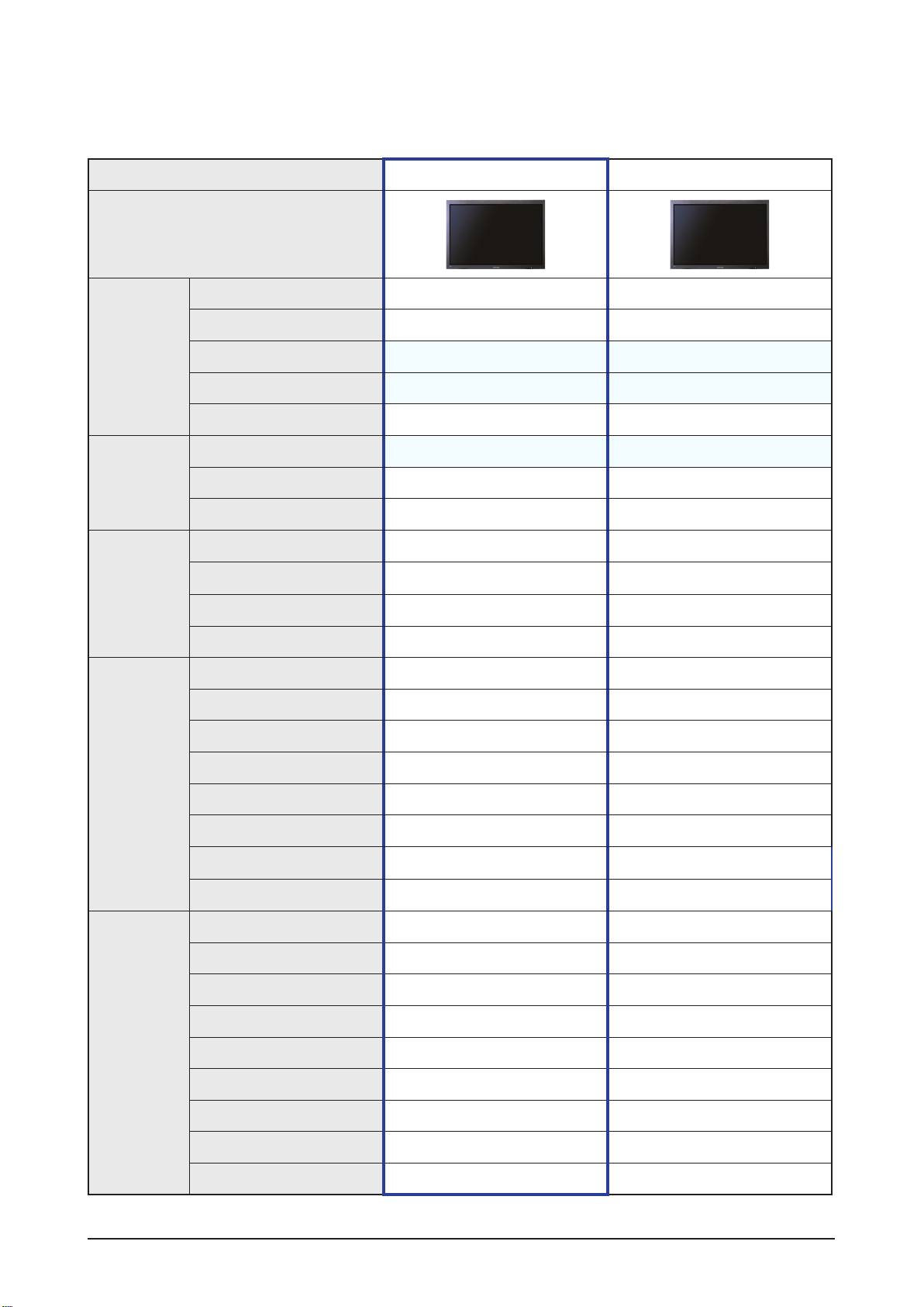
Model P64FP / P64FT (Kailas Plus) P63FT (Kailas Plus)
Design
Product Specification
Basic
Picture
Audio
Display Type
Resolution 1920 x 1080 1920 x 1080
PDP Module
Screen Size
Picture ratio
Brightness 612 cd/m2 645 cd/m2
Contrast Ratio
Picture Enhacer
Equalizer
Auto Volume Control
Surround Sound
Speaker Output
PIP X X
Double Screen
Caption X X
PDP MONITOR PDP MONITOR
S63FH-YB06 S63FH-YB05
64 inches 63 inches
16 : 9 16 : 9
40,000 : 1 40,000 : 1
X X
SRS TruSurround SRS TruSurround
10W + 10W 10W + 10W
X X
Features
Connections
Still Image
EPG X X
My Color Control
Energy Saving
Screen Burn Protection
CVBS 1 AV 1 AV
S-Video X X
Component (Y/PB/PR)
PC (D-SUB)
DVI 1 Input 1 Input
HDMI 1 Input 1 Input
Sub Woofer
Optical X X
Coaxial X X
X X
X X
1 Input 1 Input
1 Input 1 Input
X X
: Feature Included, X: Not Included
Samsung Electronics 2-3
Page 13
Product Specification
2-3 Components Function ( P64FT Only)
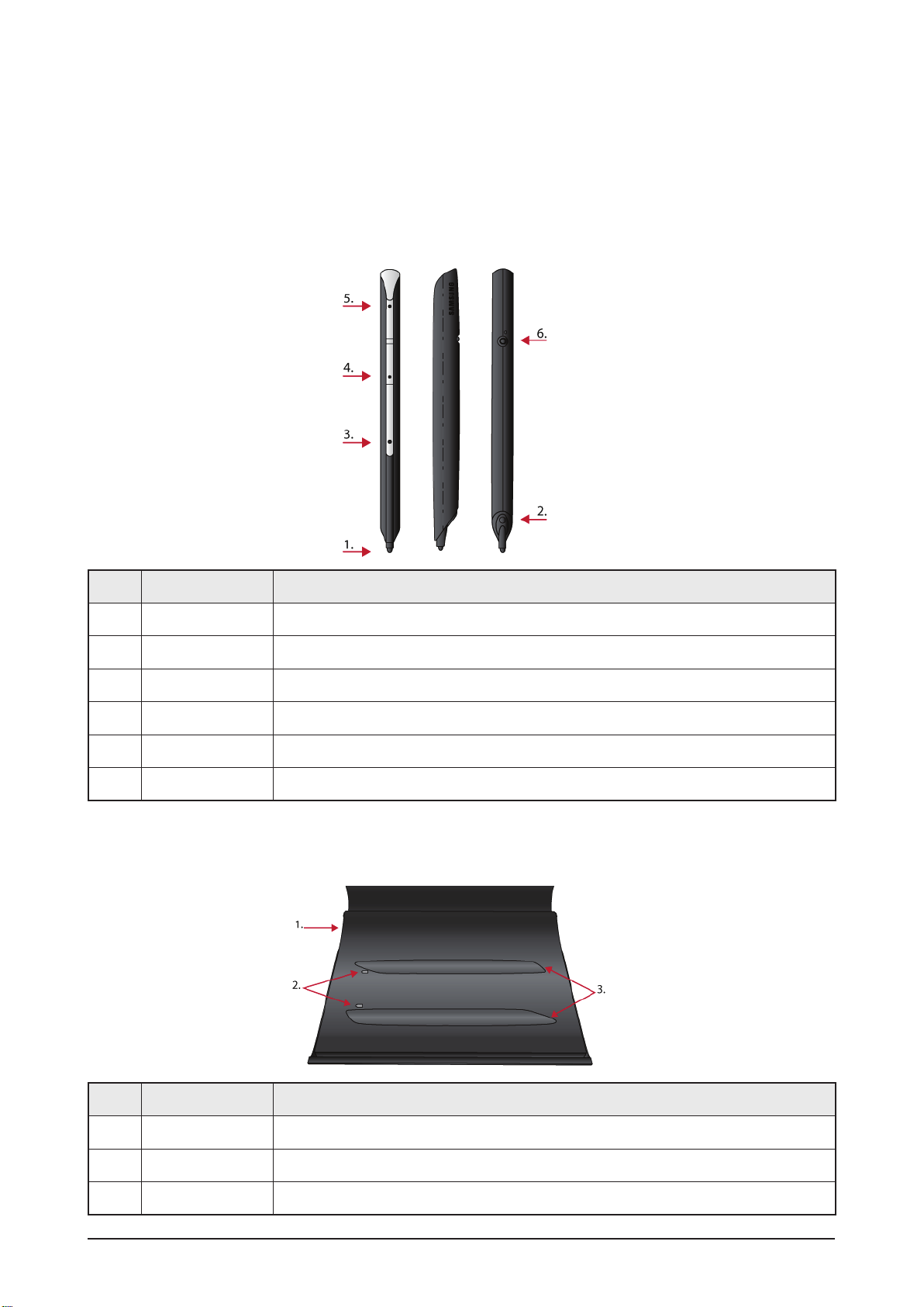
2-3-1 Pen / Cradle Function
Pen
No. Component Role
1 Pen tip The pen is writable only when the internal sensor is pressed by the pen - tip.
2 IR sensor Receive the IR signal from PDP Panel.
3 SW1 Right click function.
4 SW2 Keyboard’s Page Down function (changeable).
5 SW3 Keyboard’s Page Up function (changeable).
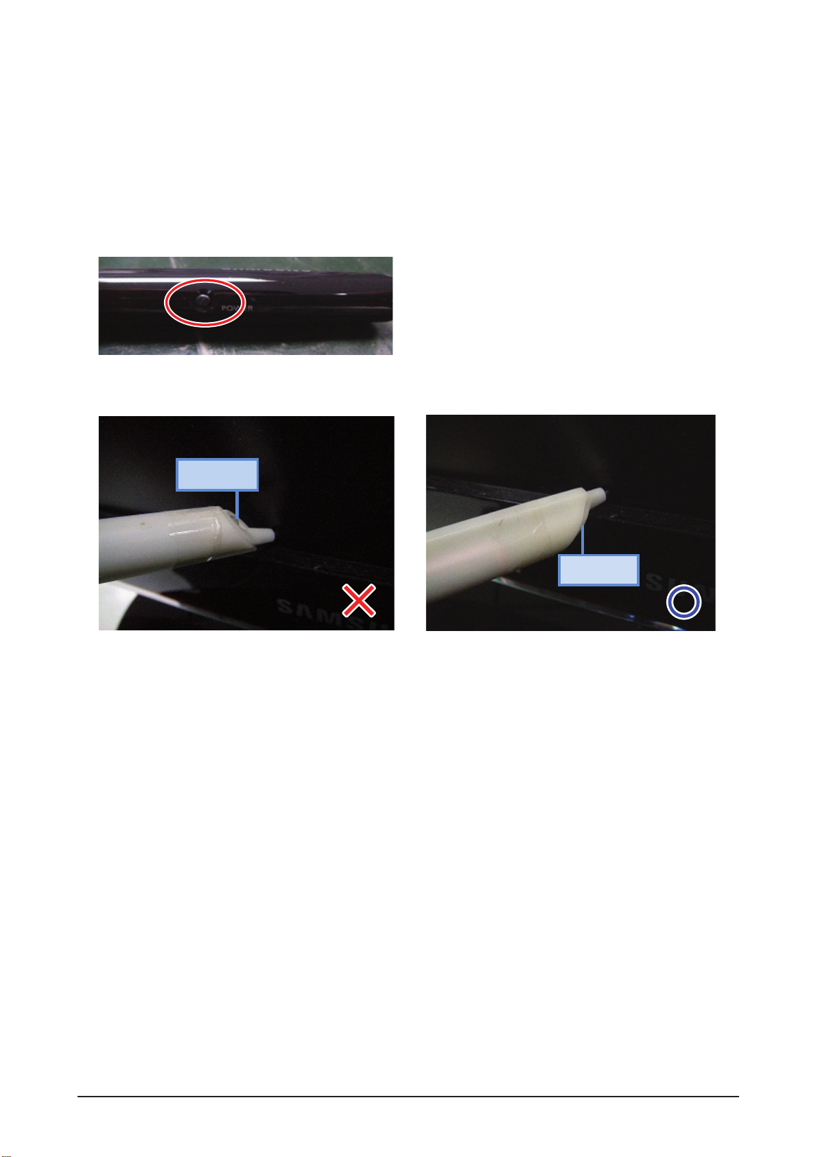
6 SW4 Power switch.
Cradle
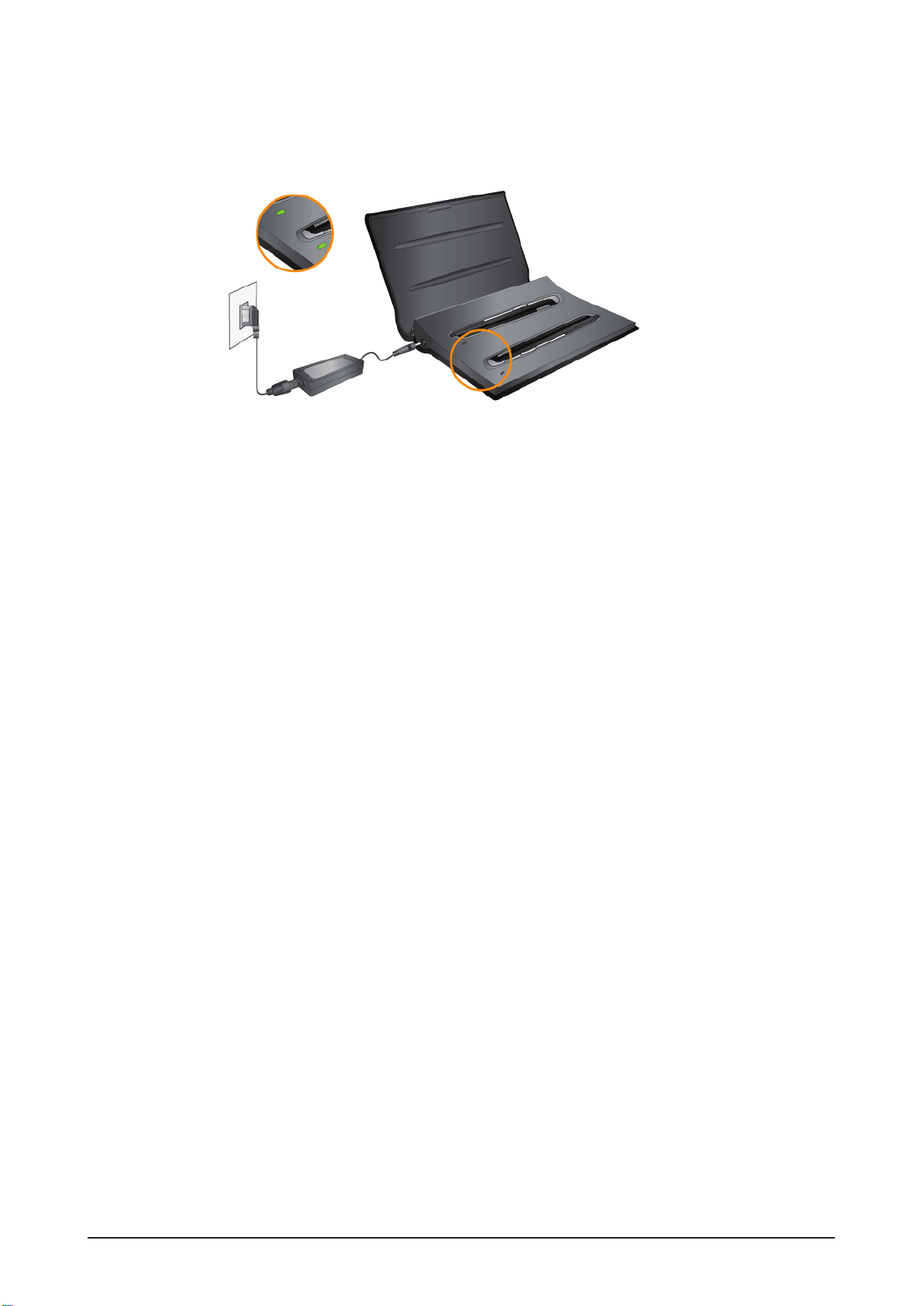
No. Component Role
1 Power Input Adapter connection terminal (power supply input).
2 LED Show the charging status.
3 Pen Placement Charging process starts once the pen is placed (by following the shape of the pen).
2-4 Samsung Electronics
Page 14
Pen Charging
► Red : In Charging, Green : Fully charged, Orange (flickering) : Error, LED off : No pen placed on Cradle.
Product Specification
Samsung Electronics 2-5
Page 15
Product Specification
IR sensor
Wrong method –IR sensor pointing UP.
Right method –IR sensor pointing DOWN.
IR sensor
2-3-2 eBoard
1. Dongle Installation
- In order to use the eBoard pen, connect the Zigbee Dongle to the USB terminal.
2. Pen Usage
- Push the black button on the lower side of the pen for 10 seconds (continuously) to switch on the pen.
Note : When using the pen on the board, make sure the IR sensor is on the below side of the pen, as
shown in the following picture.
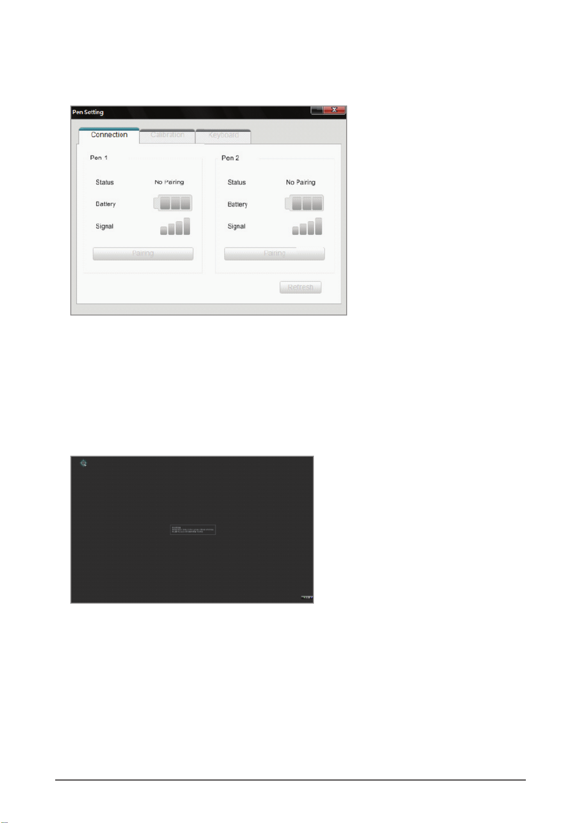
3. Connectivity of Pen and Monitor
- To connector the monitor and pen, first install the WhiteBoard program in PC. The WhiteBoard program is
provided in CD (Refer the WhiteBoard Installation method on page 112).
1) Execute Pen Pairing program in Control Panel.
(Or, click the star - shaped icon on the left hand side of menu bar. Then, click Pen Settings)
2) Push the Power button for 10 seconds, continuously, to switch on the pen.
Note
• While pushing the Power button, LED flickers once : Off → On
• While pushing the Power button, LED ickers 3 times : On → Off
2-6 Samsung Electronics
Page 16
Product Specification
3) Click the “Pairing” button on the program.
Once the Status shows “Connected”, the pairing process is done and the pen can be used on the board.
4) Pairing process is required once only. After that, pen is functioning by simply switching on the power switch
(10 seconds pairing process is not required).
4. Calibration Setting
- Execute Pen Pairing program.
- Choose the “Calibration” tab.
- Press the “Calibration Starts” button.
- Using the pen, touch exactly the center of the 4 points shown in the screen in sequence.
- Click “OK” button once the calibration finishes.
Samsung Electronics 2-7
Page 17
Product Specification
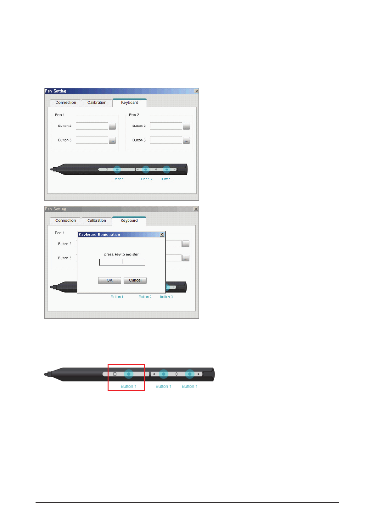
5. Keyboard Setting on Pen
- By using the WhiteBoard program, you can make the keyboard settings on the pen.
1) Choose Pen Setting > Keyboard tab on the WhiteBoard program.
2) Press any key on the keyboard to register on the Keyboard Registration menu.
6. Right Click Function
- When the pen is touching the PDP panel, press Button1 and the right click function is executed.
Note : The right click function is executable only if the pen is touching the PDP Panel.
2-8 Samsung Electronics
Page 18
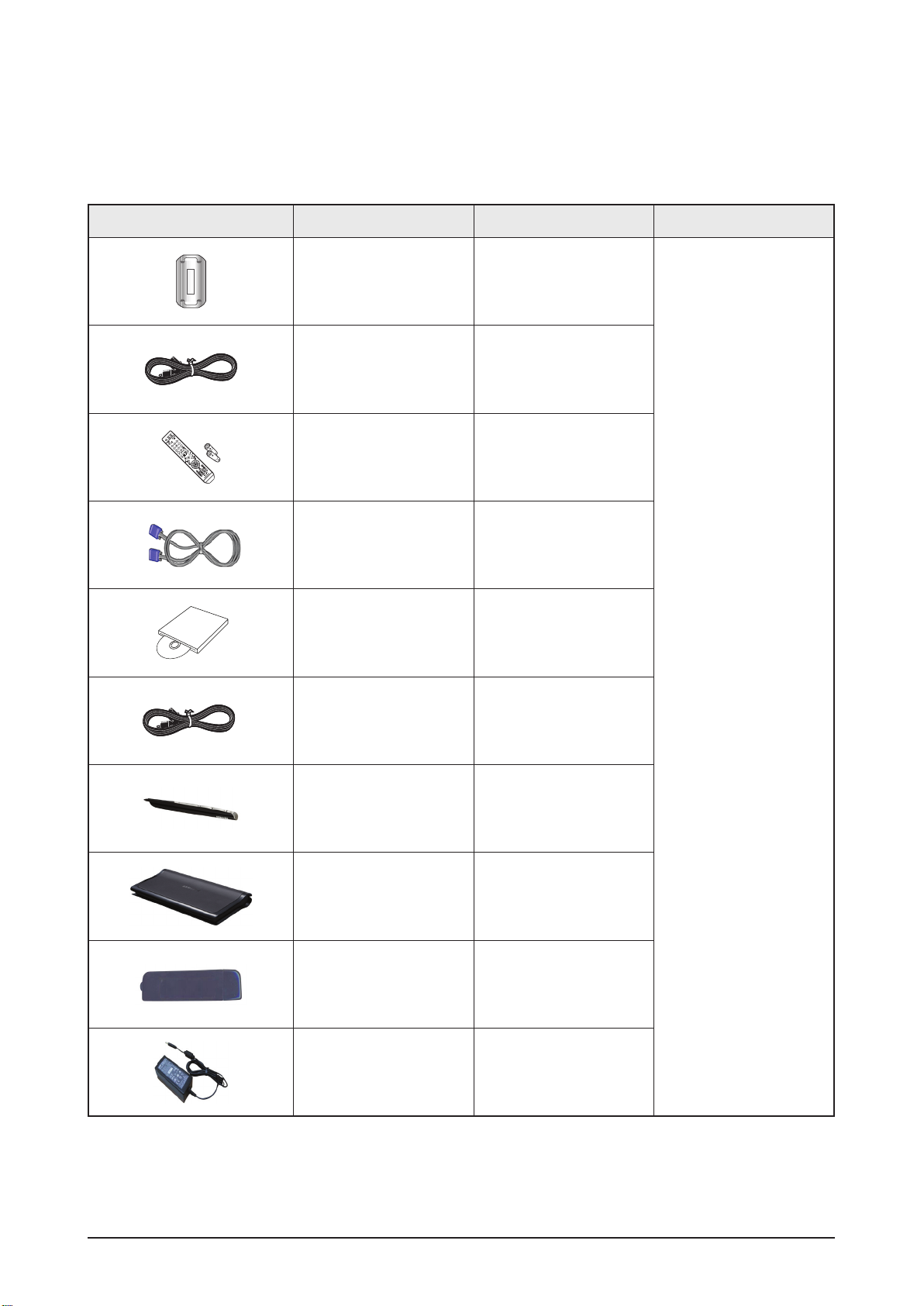
2-4 Accessories
2-4-1 Supplied Accessories
Accessories Item Item code Remark
Product Specification
Ferrite Core for
Power Cord
Set Power Cord 3903-000455
Remote Control
Batteries
D-Sub Cable BN39-00244H
S/W Driver
Cradle Power Code -
-
BP59-00138A
BN43-00004A
BN59-00779D
P64FT Only
- Cradle Power Code,
Electronic Pen, Cradle,
Zigbee Dongle,
Adaptor /
Samsung Service Center
Electronic Pen -
Cradle -
Zigbee Dongle -
Adaptor -
Samsung Electronics 2-9
Page 19

MEMO
2-10 Samsung Electronics
Page 20
3.拆卸和重新组装
3-1 整体拆卸和重新组装
-在拆卸本机前,务必拆开电源线。
-当拆开带有大容量电容器的主板(如 SMPS、X 主板、Y 主板等等)时,首先给电容器放电。(电
荷可能产生火花,有触电危险。)
-当拆卸和组装本机时,参照电路图检查电缆是否接好,并小心不要损坏电缆。
-小心不要在正面的滤光镜中造成缺陷。
-按与拆卸相反的顺序组装电路板。
-必须将等离子屏置于铺有垫子的平坦表面上,以便拆卸和重新组装。
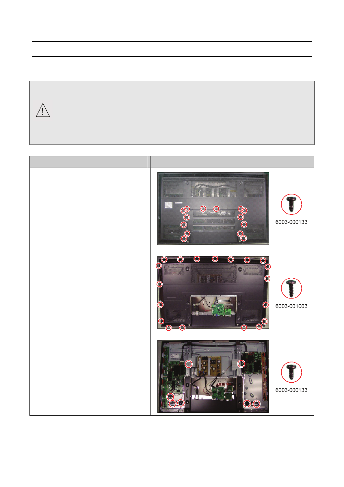
说明 说明相片
1. 拆卸 14 个螺钉。
:BH,+,-,S,M4,L8,ZPC(BLK),SWRCH18A
* L:螺钉长度 (mm)
2. 拆卸机架端子。
3. 拆卸 19 个螺钉。
:BH,+,-,B,M4,L12,ZPC(BLK),SWRCH18
* L:螺钉长度 (mm)
4. 拆卸后盖。
5. 拆卸 7 个螺钉。
:BH,+,-,S,M4,L8,ZPC(BLK),SWRCH18A
* L:螺钉长度 (mm)
6. 拆卸扬声器和风扇组件。
三星电子 3-1
Page 21
拆卸和重新组装
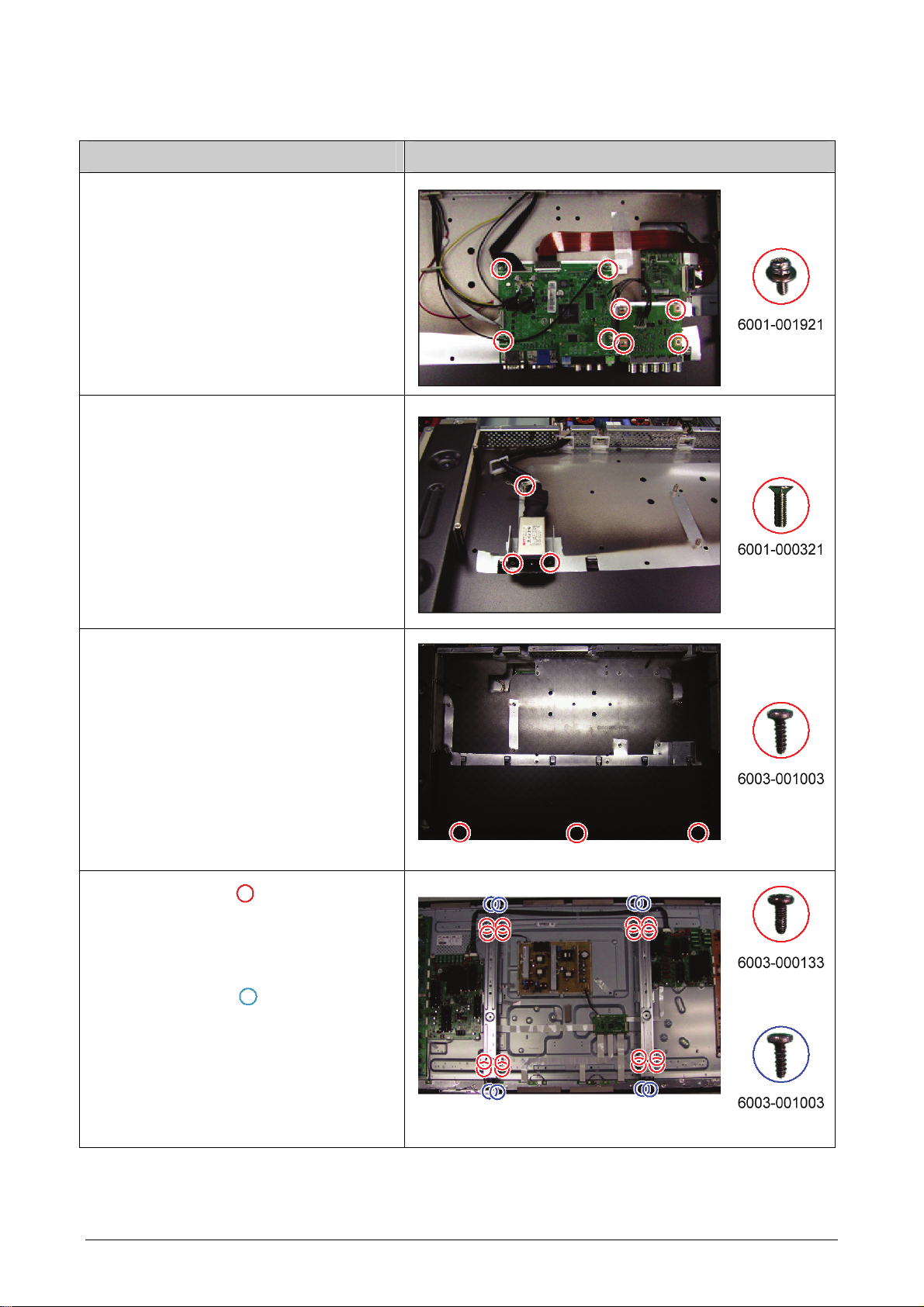
说明 说明相片
7.拆卸主板和BNC板上的所有连接器。
拆卸 8 个螺钉。
8.
:BH,+,WSP,M3,L8,NI PLT,SWRCH18A
* L:螺钉长度 (mm)
9.拆卸主板和 BNC 板。
10.拆卸 3 个螺钉。
:FH,+,M3,L10,NI PLT,SWRCH18A
* L:螺钉长度 (mm)
11.拆卸 EMI AC 滤过线。
12.拆卸 3 个螺钉。
:BH,+,B,M4,L12,ZPC(BLK),SWRCH18
* L:螺钉长度 (mm)
13.拆卸后盖-P SUB 组件。
14.拆卸16个螺钉。( )
:BH,+,-,S,M4,L8,ZPC(BLK),SWRCH18A
* L:螺钉长度 (mm)
15.
拆卸 8 个螺钉。( )
:BH,+,M4,L16,ZPC(BLK)
* L:螺钉长度 (mm)
16.拆卸墙架。
在拆卸前盖时,将等离子屏板面朝下放置在
软布上。
3-2 三星电子
Page 22
说明 说明相片
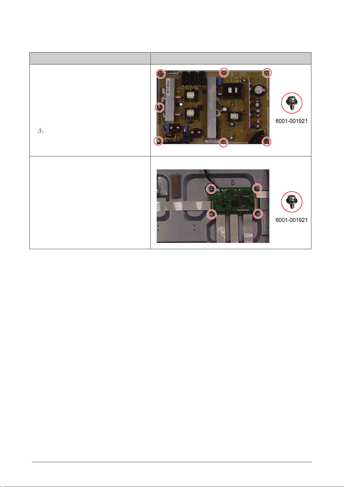
17.拆卸SMPS上的所有连接器。
拆卸 7 个螺钉。
18.
:PH,+,WSP,M3,L8,NI PLT,SWRCH18A
* L:螺钉长度 (mm)
19.拆卸SMPS。
在处理电源板时要带上手套,以免电容
器中残留电荷。尤其,要避免去触摸电
容器的任何部分。
拆卸和重新组装
20.拆卸逻辑板上的所有连接器。
21.拆卸 4 个螺钉。
:PH,+,WSP,M3,L8,NI PLT,SWRCH18A
* L:螺钉长度 (mm)
22.拆卸逻辑板。
三星电子 3-3
Page 23

拆卸和重新组装
说明 说明相片
23.拆卸X缓冲板上的所有连接器。
※如要拆卸X主板上的扁平线,按住连接器
的上部和下端。
24 拆卸 8 个螺钉。
:PH,+,WSP,M3,L8,NI PLT,SWRCH18A
* L:螺钉长度 (mm)
3-4 三星电子
Page 24

拆卸和重新组装
说明 说明相片
25.拆卸 4 个螺钉。
:PH,+,WSP,M3,L8,NI PLT,SWRCH18A
* L:螺钉长度 (mm)
26.拆卸带有X缓冲板的X主板。
27.拉动顶部和底部托架,并将 Y 缓冲板连
接器从屏板处卸下。
三星电子 3-5
Page 25

拆卸和重新组装
说明 说明相片
28.拆卸 7 个螺钉。
:PH,+,WSP,M3,L8,NI PLT,SWRCH18A
* L:螺钉长度 (mm)
29.拆卸Y缓冲板。
30.拆卸 Y 主板上的所有连接器。
31.拆卸 8 个螺钉。
:PH,+,WSP,M3,L8,NI PLT,SWRCH18A
* L:螺钉长度 (mm)
32.拆卸 Y 主板。
3-6 三星电子
Page 26

拆卸和重新组装
说明 说明相片
33.在拆卸功能板前卸下 3 处螺钉。
:RH,+,B,M4,L15,ZPC(BLK),SWRCH18
* L:螺钉长度 (mm)
三星电子 3-7
Page 27

拆卸和重新组装
备忘录
3-8 三星电子
Page 28

4.故障排除
4-1 故障排除
4-1-1 故障排除第一检查表
1. 首先检查各种电缆连接。
-检查电缆是否烧坏或损坏。
-检查电缆是否断开或连接处太松。
-依据连接图检查是否连接电缆。
2. 检查主板的电源输入。
3. 检查 SMPS主板之间、SMPSX、Y 主板之间和逻辑板之间的电压输入和输出。
故障排除
三星电子 4-1
Page 29

故障排除
4-1-2 按错误模式分类的检查点
未通电
-当连接电源线时,前面板上的 LED 指示灯不工作。
征兆
主要检查表
小心
-当连接电源线时,SMPS 继电器不工作。
-设备的电源似乎有故障。
通常,在板块连接到 SMPS 上发生故障时,SMPS 会自动重复的打开和关闭:
-连接所有的线缆到 SMPS,检查 SMPS 是否正常工作,输出电压是否正常。
-如果症状仍然存在,更换 SMPS。
-如果 SMPS 在待机模式下运行时,症状消失,挨个查找引起故障的线缆。
当拆开和连接 SMPS,X 主板和 Y 主板等电缆时,大容量电容器的电荷可能产生火
花。因此,在从本机拆开电源线后等待一些时间。
未通电
AC 插座连接器和
SMPS CN800 的连接是
否正确?
否
将其正确连接。
是
※参看图 4-1 中图像。
STD 5V 电压或CN801
上 PS_ON 上 0V?
是
更换SMPS
否
更换主板
※参看图 4-1 中图像。
4-2 三星电子
Page 30

故障排除
<图.4-1>
三星电子 4-3
Page 31

故障排除
当本机重复打开和关闭时
征兆 SMPS 继电器被重复打开和关闭
通常,在板块连接到 SMPS 上发生故障时,SMPS 会自动重复的打开和关闭:
主要检查表
小心
-连接所有的线缆到 SMPS,检查 SMPS 是否正常工作,输出电压是否正常。
-如果症状仍然存在,更换 SMPS。
-如果 SMPS 在待机模式下运行时,症状消失,挨个查找引起故障的线缆。
当拆开和连接 SMPS,X 主板和 Y 主板等电缆时,大容量电容器的电荷可能产生火
花。因此,在从本机拆开电源线后等待一些时间。
当本机被重复打开和关闭时
从 SMPS 上卸下 CN804
后接通电源,症状是否
仍然存在?
否
更换Y主板
是
※参看图 4-2 中图像。
从 SMPS 上卸下
CN4008 后接通电源,
症状是否仍然存在?
否
更换X主板
是
A
※参看图 4-2 中图像。
4-4 三星电子
Page 32

故障排除
CN802 后接通电源,症
A
从 SMPS 上卸下
状是否仍然存在?
是
更换 SMPS
否
※参看图 4-2 中图像。
更换逻辑主板
三星电子 4-5
Page 33

故障排除
<图.4-2>
4-6 三星电子
Page 34

无画面(当音频正常时)
征兆 -音频正常,但屏幕上不显示画面。
主要检查表
小心
-当主板正常,但 X、Y 主板、逻辑板或 Y 缓冲器板出现故障时,可能出现这种情况。
-当 LVDS 电缆不能被连接到主板时,SMPS 的输出电压可能出现这种情况。
当拆开和连接 SMPS,X 主板和 Y 主板等电缆时,大容量电容器的电荷可能产生火
花。因此,在从本机拆开电源线后等待一些时间。
故障排除
无图片
拆卸 SMPS 上的所有接
线并检查 Vs 和 Va 上的
电压是否正常?
是
故障是否解决?
是
否
※参看图 4-3 中图像。
否
更换SMPS
更换Y主板
故障是否解决?
是
B
否
更换X主板
三星电子 4-7
Page 35

故障排除
B
故障是否解决?
否
更换逻辑板
是
※参看图 4-3 中的图像
故障是否解决?
否
更换主板
4-8 三星电子
Page 36

故障排除
<图.4-3>
三星电子 4-9
Page 37

故障排除
无声音
征兆
主要检查表
-可能是由于扬声器连接器连接不正确或被损坏而引起的。
-可能是由于主板声音板块不能正常运行,或扬声器故障的原因。
-当主板正常,但 X、Y 主板、逻辑板或 Y 缓冲器板出现故障时,可能出现这种情况。
-当 LVDS 电缆不能被连接到主板时,SMPS 的输出电压可能出现这种情况。
无声音
扬声器的接线是否正确
连接到主板?
是
将接线正确连接,或在必要时更换
接线。
否
检查 CN801 上管脚7,8
电压是否为 12V?
否
更换SMPS
是
※参看图 4-4 中图像。
在主板上是否可以检
测到扬声器的输出。
否
更换主板。
是
更换扬声器。
※参看图 4-4 中图像。
4-10 三星电子
Page 38

故障排除
<图.4-4>
三星电子 4-11
Page 39

故障排除
V
SMPS 故障排除
开机
正常
STD_5
异常
检查 U101、D108
正常
PFC
异常
检查 U201、Q203、Q204
VA
异常
多种
检查 U501
异常
检查 U601
正常
VS
异常
正常
检查其它板
(主板或驱动板)或线缆
检查 Q401、Q402
4-12 三星电子
Page 40

故障排除
驱动板故障排除
1. 故障排除摘要
状态名称 说明 相关电路板
无电压输出 工作电压不存在
无显示 工作电压存在,但屏幕上没有图像 Y主、X 主、逻辑主、电缆
异常显示 屏幕上有异常图像(未开路或短路) Y主、X 主、逻辑主
持续开路 屏幕上没有一些水平线 扫描缓冲器、X/Y 的 FPC
持续短路 一些水平线似乎在屏幕上连接 扫描缓冲器、X/Y 的 FPC
地址开路 屏幕上没有一些竖直线 逻辑主、逻辑缓冲器、TCP
地址短路 一些竖直线似乎在屏幕上连接 逻辑主、逻辑缓冲器、TCP
PSU
三星电子 4-13
Page 41

故障排除
开路
开路
短路
常 短路
否
是否是
2. 异常状态下的故障排除步骤
1)无显示(操作电压存在,但不存在显示屏上)
►无显示与 Y 主板、X 主板、逻辑主板等等相关。
本页说明如何检查电路板,下页说明如何查找有缺陷的电路板。
无显示
[逻辑主]
LED 指示灯闪烁
[Y 主]
检查所需点
[逻辑主]
检查是否供电(5V、3.3V)
检查 LED 运行情况
检查内部是否为
默认黑色
检查是否检测到
地址数据输出
检查 MICOM 运
行情况
检查 ASIC 控制
信号输出
检查电源连接情况
检查 DDR 和
ASIC 之间的数
据和控制信号是
否正常
[X 主]
检查所需点
检查保险丝
检查输入电压
如果输入电压异
常,更换 PSU,并
再次检查 PSU,因
为这种情况说明
PSU 输出错误。
[Y 主]
检查几点
保险丝
正常
FET/二
极管
正
更换电路板
更换电路板
[X 主]
检查几点
保险丝
正常
FET/二
极管
正常
更换电路板
更换电路板
Y 主
正常状态
X 主
正常状态
4-14 三星电子
Page 42

开路 开路
短路
常正常
短路
常正常
否
是
2)异常显示(屏幕上有异常图像,持续或地址异常除外)
►异常显示与 Y 主板、X 主板、逻辑主板等等相关。
本页说明如何检查电路板,下页说明如何查找有缺陷的电路板。
异常显示
故障排除
[逻辑主]
观察异常显示
[逻辑主]
LED 指示灯闪烁
(Vsync 作用)
定期异
更换电路板
[Y 主]
检查几点
检查所需点
逻辑主板
状态正常
更换显示屏
[Y 主]
[X 主]
检查所需点
[X 主]
检查几点
保险丝
正
FET
Y 主
正常状态
更换电路板
更换电路板
保险丝
正
FET
X 主
正常状态
更换电路板
更换电路板
三星电子 4-15
Page 43

故障排除
否
常
检查状态
否
常
检查状态
3)持续开路(一些水平线在屏幕上不存在)
[Y-FPC]
持续开路
在更换 Y 缓
冲器后,重新
更换显示屏
FPC 上有缺陷
正
完成
(Y 缓冲器有缺陷)
4)持续短路(一些水平线在画面上连接)
(多余扫描线路放电)
[Y-FPC]
持续短路
在更换 Y 缓
冲器后,重新
正
完成
(Y 缓冲器有缺陷)
更换显示屏
FPC 上有缺陷
4-16 三星电子
Page 44

否正常
5)地址开路、短路(屏幕上不存在竖直线)
►地址开路和短路与逻辑主板、逻辑缓冲器板、FFC、TCP 膜等等相关。
本页说明如何检查电路板,下页说明如何查找有缺陷的电路板。
故障排除
检查 LED 运行情况
[逻辑主]
地址开路/短路]
检查内部模式屏幕是
正常
在 MICOM 中重新装载数
据,并重新检查 MICOM
检查详细波形,并控制
信号波形
否
检查视频板
正常 正常
检查是否异常显示具
体的 TCP 块画面
检查在缓冲器板和逻辑
主板地址数据输出部分
上是否有开路或短路。
检查 FFC 连接状态
更换逻辑主板/地址缓冲器板(E 或 F)/FFC
否
否
检查 DDR 输入电压
(Vref)
否
检查 DDR 输入电
检查电压分配器
压(Vref)。
否
完成
否
更换显示屏
三星电子 4-17
Page 45

故障排除
4-1-3 故障及更正措施
征兆 相关图像 原因和解决办法
屏幕上出现竖直空白单元格
(块)。
地址缓冲器缺陷
打开电视时出现绿屏。
出现 OSD 框,但无文字。
-更换相应上/下缓冲器(E、F 或G)
COF 缺陷(烧断)
-更换模块
未重设定标
-更换主板
程序版本错误
-检查各个程序版本
-更换主板
屏幕上出现上(或下)空白块。
上/下 Y 缓冲器缺陷
-更换相应上/下缓冲器
4-18 三星电子
Page 46

故障排除
征兆 相关图像 原因和解决办法
未显示主或副图片。
屏幕上出现竖直绿线。
暗淡屏幕(红色模糊屏幕)
更换主板
SMPS 电压错误
-根据模块标签上印刷的电压调
节 SMPS 电压
X-主板缺陷
-更换 X-主板
三星电子 4-19
Page 47

故障排除
4-1-4 按组件分类的故障排除步骤
组件 主要征兆
SMPS-PDP TV
ASSY PDP P-X-MAIN BOARD
ASSY PDP P-Y-MAIN BOARD
ASSY PDP P-LOGIC MAIN BOARD
ASSY PDP P-X BUFFER UPPER BOARD
ASSY PDP P-X BUFFER LOWER BOARD
ASSY PDP P-Y BUFFER UPPER BOARD
ASSY PDP P-Y BUFFER LOWER BOARD
ASSY PDP P-E-BUFFER BOARD
ASSY PDP P-F-BUFFER BOARD
ASSY PDP P-G-BUFFER BOARD
ASSY PCB MISC-MAIN
ASSY BOARD P-BNC
ASSY BOARD P-FUNCTION
ASSY ACCESSORY-PEN
ASSY ACCESSORY-CRADLE
ASSY ACCESSORY-USB DONGLE
※如果发生大的故障,按照下表所示检查各组件。
没有通电,空白屏幕,继电器重复开和关。
空白屏幕
空白屏幕
空白屏幕,屏幕噪声
上部屏幕空白
下部屏幕空白
上部屏幕空白
下部屏幕空白
相应的缓冲器板块屏幕空白
相应的缓冲器板块屏幕空白
相应的缓冲器板块屏幕空白
未通电,各输入源屏幕异常、画中画屏幕故障、声音
故障
当输入模式为 BNC 时无信号
功能键不能正常运作
遥控器不能正常运作,LED 不能正常运作
笔功能失败,充电不能正常运作。
不能与软件狗通信
充电不能正常运行
不能与笔通信
4-20 三星电子
Page 48

故障排除
4-1-5 笔/支架的故障排除(※仅适用于 P64FT)
故障排除-笔
►如果发生以下问题,首先尝试给笔充电。
如果再次发生问题 – 请联系服务中心。
1.当按下电源开关时,笔的 LED 不能正常运作。
2.当按下电源开关(正常),笔 LED 的颜色是红色。尽管如此,按下开关 1,2 或 3 时 LED 不变成蓝色。
►如果发生以下问题,请联系服务中心。
1.即使开关 1,2 或 3 没有被按下,笔 LED 显示为红色/蓝色。
2.当按下开关 1,2 或 3,LED 是红色。
(规格:按下电源开关时 LED 为红色,按下开关 1,2 或 3 时为蓝色)
3.当在电子板上使用笔时,写的是不顺畅并在屏幕上不时显示的字/行被切断。
4.当笔被安放到位时,支架 LED 不停闪烁。
5.在被充电一段时间后笔不能正常运作,并 LED 显示绿色。
(已充满电)
►如果发生以下问题,应用下表所述的解决方案。
问题 解决方案
电子板上的点位与笔的点位不相匹
配。
笔的对接不能完成。
执行校准菜单并调节点位。
从 USB终端位置取下软件狗并重新连
接(为复位的缘故)。
故障排除 – 支架
►如果发生以下问题,请联系服务中心。
1.在第一次连接适配器时,支架 LED 不显示任何色彩。
2.当适配器连接上时支架 LED 闪烁。(没有放置笔)。
3.按照规格,支架 LED 不显示色彩。
(LED 规格 - 绿色:完全充电,红色:在充电中时,橙色(闪烁):错误,支架上没有笔:LED 关闭)。
三星电子 4-21
Page 49

故障排除
4-2 调节
4-2-1 维修说明
在进行售后服务之前
1. 检查测量和测试设备运行是否正常。
2. 确保有足够工作空间,用于拆卸产品。
3. 准备软垫,用于拆卸产品。
更换电路板后的维修调节项目
<如有调节设备可用>
1. 工厂模式 PDP 选项→将工厂数据类型项目设为相关机型的适当值。
2. 调节各个模式的工厂模式的校准
3. 调节工厂模式的白平衡
<如无调节设备可用>
1. 写下工厂模式 HDMI 白平衡的值,然后更换电路板。
2. 工厂模式的 PDP 选项→将工厂数据类型项目设为相关机型的适当值。
3. 用之前记录的值设置 HDMI 白平衡的值。
4-22 三星电子
Page 50

4-2-2 如何进入维修模式
1. 通用遥控
如欲进入: 关机 信息 菜单 静音 开机
如欲退出: 关机 开机
2.工厂遥控
如欲进入: 开机 信息 工厂按键 (击键间隔:不到3秒)
如欲退出:按下工厂按键两次。(按一次进入到缓慢模式)
3. 当进入工厂模式时设置
-清晰屏幕(动态)、色调(冷色 1)、工厂(动态 CE 关)
4.调节步骤
-频道▲▼键:选择项目
-音量◄►键:调大或调小值。
故障排除
-菜单键:将修改内容存入 EEPROM,并返回上一级模式。
-使用数字(0~9)键,可以选择频道。
-使用信号源键,可以切换 AV 模式。
5. 初始维修模式显示状态
自动颜色控制
按 R/G/B 偏移、增益调节色彩
调节屏幕效果和清晰度
显示 PDP 的内部逻辑信息(版本,温度)
调节视频和声音的同步效果
调节 Y 和 C 的同步
设定波特率,是否运行 nMFM,是否运行风
扇,温度设定及长线连接选项。
MICOM 代码的系列编号(4 位数)
三星电子 4-23
采用扩频
工厂复位
MICOM 代码的版本
Page 51

故障排除
4-2-3 工厂数据
自动色彩部分
白平衡部分
仅限于 PC 模拟(1024x768@60 16 灰度图)
通常颜色控制仅在某些图案的某些模式下运
行,但在其他情况下,运行可使颜色失真。
同样,当在 XGA 60Hz 以外的模式下控制颜
色时,颜色控制不正确。
需要格外小心!!
仅限于音频(检查板面模式)
通常颜色控制仅在某些图案的某些模式下运
行,但在其他情况下,运行可使颜色失真。
需要格外小心!!
用于颜色控制。
但过度设置可能使颜色饱和。
需要格外小心!!
开:显示工厂调节值
关:显示默认设置值
在定标器中的注册值
红色/蓝色/绿色
调节增益和偏移
4-24 三星电子
Page 52

MST9788CLD 部分
PDP 逻辑部分
故障排除
-通过增益和偏移为每个
视频源调节色彩。
-调节显示图像的清晰度及细
节。
-调节黑电平延伸(BLE)技术
中的黑电平明细。
设置模式到测试内部 PDP 逻辑,并显示 PDP
板的版本及温度信息。
-如要使用 eBoad,笔触摸模式一定要为“开启”状态。
三星电子 4-25
Page 53

故障排除
音频部分
YC 延迟部分
设置音频延迟(调节每个视频源音频和声音的同步)
在每个 AV 视频信号中调节 Y(亮度信号)和
C(色度信号)的同步。
4-26 三星电子
Page 54

扩频/复位部分
故障排除
扩频调节
扩频应用状态
幅度和期间设置
扩展复位:在维修菜单中复位到默认设置,在复位后需要开/关电
源。
三星电子 4-27
Page 55

故障排除
选项/复位检验和部分
如果选择该项,显示关于 Micom
代码的 4 位系列号。
选项调节
-波特率速度设定(波特率值为 9600)
-功能键设定/取消设定
-网络端口的选项设定
-音频延迟设定(视频和音频的同步设定)
-信息显示不适宜分辨率模式的设定/取消设定。
-PC 线缆的检测设定/取消设定。
-检查状态
y风扇的速度设定
*是否当前的温度值高于温度的控制值。
显示屏进入到保护模式
(背景灯关闭和功能 LED 变更色彩[绿色到橙色])
*当前显示屏的内部温度。
-由于 HDMI 热插的检测,在执行复位前设定延迟值。
-由于 DVI 热插的检测,在执行复位前设定延迟值。
-PDP LOGIC
-设定风扇开/关。
-在使用 HDMI/DVI 长线时使用。
4-28 三星电子
Page 56

4-2-4 维修调节
-在白平衡调节时必须要对方格模式进行校准。
自动色彩
故障排除
仅限于 PC 模拟(1024x768@60 16 灰度
图)
通常颜色控制仅在某些图案的某些模式下
运行,但在其他情况下,运行可使颜色失真。
同样,当在 XGA 60Hz 以外的模式下控制
颜色时,颜色控制不正确。
需要格外小心!!
仅限于 AV(检查板面模式)
通常颜色控制仅在某些图案的某些模式下
运行,但在其他情况下,运行可使颜色失真。
需要格外小心!!
三星电子 4-29
Page 57

故障排除
白平衡
调节规格:
1. 信号源:HDMI
2. 设置模式:1280*720@60Hz
3. 图形:图形#92
4. 设用设备:
MIK-7256 (MSPG925L)
5. 操作顺序
1)连接 MIK-7256 的 DVI 输出端子(MSPG925L)到主机上的 HDMI 输入端子。
2)设置输入模式为 HDMI。
3)进入维修模式的白平衡菜单。
4)连接 CA-210 感应器到滤光镜。
(CA210 探针的固定位置)
4-30 三星电子
Page 58

5)调节弱光
-调节副光度并设置“Y”值。
-调节 R 偏移(”X”)和 B 偏移 (“Y”)到颜色坐标。
*不要调节 G-偏移数据。
6)调节高光
-调节 R 增益(”X”)和 B 增益 (“Y”)到颜色坐标。
*不要调节 G-增益数据。
输入模式
故障排除
三星电子 4-31
Page 59

故障排除
4-2-5 更换和校准
*在更换各组件之后列出的检查项目
更换组件项目 检查项目
ASSY PCB MISC-MAIN
SMPS-PDP TV
ASSY PDP P-X-MAIN BOARD
ASSY PDP P-Y-MAIN BOARD
ASSY PDP P-LOGIC MAIN BOARD
ASSY PDP P-X BUFFER UPPER BOARD
ASSY PDP P-X BUFFER LOWER BOARD
ASSY PDP P-Y BUFFER UPPER BOARD
ASSY PDP P-Y BUFFER LOWER BOARD
ASSY PDP P-E-BUFFER BOARD
ASSY PDP P-F-BUFFER BOARD
ASSY PDP P-G-BUFFER BOARD
ASSY BOARD P-FUNCTION
ASSY BOARD P-BNC
1) 自动程序
2) 白色平衡调节
检查并调节 Vs、Va 电压
不调节
※在更换 SMPS 或 PDP 显示屏时,必须检查显示屏上印刷的电压标签并进行调节。
4-32 三星电子
Page 60

电压标签
■ 调节电压
1. 在更换 SMPS 或 PDP 显示屏后,必须参照显示屏上印刷的电压标签调节该电压。
(如果未调节该电压,可能出现异常放电征兆。)
值 调节电路板
Vs 200
Va 63
Vset -
SMPS
Ve 94
Vsc -190
2. 主 SMPS 电压调节点。
VS 测试点
VS 调节
VS 测试点
故障排除
SMPS
VA 调节
三星电子 4-33
Page 61

故障排除
4-3 升级
4-3-1 如何给闪存 ROM 升级
1.使用 D-SUB 接线和 D/L 工具连接计算机和 PDP。
2.运行闪存下载程序 ISP_Tool v4.3.0
3.点击“连接”按钮。
4.现在已建立机体连接。
点击“确认”。
D-SUB 接线
D/L 装置图
4-34 三星电子
Page 62

5.连接电源线并点击“读取”。
6.点击新的“读取”按钮。
7.选择升级文件。
8.点击“自动”按钮,取消 Blank 和检验选项并点击“运行”。
9.下载程序条出现且 D/L 信息显示在信息窗口中。
故障排除
三星电子 4-35
Page 63

故障排除
4-3-2 如何检查程序版本
1. 在工厂菜单中的检查步骤。当进入工厂模式时,在菜单
的最底部显示软件版本。
主程序,SUB-MICOM 程序版本
启动-代码版本
4-3-3 DDC 管理器
< DDC MANAGER:MTI - 2510>
4-36 三星电子
Page 64

4-3-4 DDC 管理器 – 系统固件升级方法
1.运行“winDDCU.exe”
2.选择“EDID Multi – Writer”。
故障排除
三星电子 4-37
Page 65

故障排除
3.按下“载入”可载入.hex 文件。
(选择模拟/DVI/HDMI 取决于输入源)
4.按下“写入和检验”按钮且下载程序开始,当下载完
成,将会显示信息“在显示器中进行检验→确认”。
4-38 三星电子
Page 66

6. Wiring Diagram
CN5400
CN5412
CN5413
CN5505
CN5508
CN5507
CN5005
CN804
CN802
CN2000
CN2002
CN2003
CN2501
CN2509 CN2605 CN2606 CN2708
CN2701
CN4002
CN4001
CN4005
CN801
CN2005CN2004
SMPS
Y- MA
I
N SCAN
X- D
R
I
VE
Y- D
RI
VE
CN2508
E-BUFFER G-BUFFER
L
OG
IC BO
A
R
D
CN5010
CN5002
CN5004
CN4003
CN4004
CN4006
CN4007
CN4501
CN4502
CN4603
CN4605
CN4606
CN4604
CN803
CN5003
CN5006
CN5007
CN5008
CN5009
CN800
AC
I
NLET
X- M
AI
N
SCAN
CN101
FUNCTION
SPEAKER
CN102
CN501
MAIN BOARD
BNC BOARD
CN403
CN701
CN503
CN2
7
8
1
CN2007
CN2006
F-BUFFER
CN2601
6
9
2
5
4
3
6-1 Overall Wiring
Wiring Diagram
Samsung Electronics 6-1
Page 67

Wiring Diagram
The code number of cable(Lead-connector) can be changed, see “5. Exploded View & Part List.”
Cable (Lead-connector)
Use
Code BN96-20026A
Photo
Use
Code BN39-01150B BN39-01092H
Photo
1
LVDS FPCB
8
BNC Connector
Speaker Connector
2
POWER
BN39-01088D 2901-001656
9
7
FILTER-EMI AC LINE
Fan
Use Fan 1
Code BN31-00026M
Photo
Fan 2 Fan 3
BN31-00026L BN31-00029B
6-2 Samsung Electronics
Page 68

6-1-1 Pin Connection
Wiring Diagram
1
CN403 (MAIN Board) ↔ CN2002 (LOGIC Board)
Pin No.
1 PDP_GO 18 RxCLKIN2+ 35 RxEIN3-
2 GND 19 GND 36 RxEIN3+
3 3D_SYNC 20 RxOIN3- 37 RxEIN4-
4 GND 21 RxOIN3+ 38 RxEIN4+
5 GND 22 RxOIN4- 39 GND
6 GND 23 RxOIN4+ 40 N/C
7 N/C 24 GND 41 N/C
8 N/C 25 RxEIN0- 42 N/C
9 GND 26 RxEIN0+ 43 GND
10 RxOIN0- 27 RxEIN1- 44 UART Rx
11 RxOIN0+ 28 RxEIN1+ 45 GND
12 RxOIN1- 29 RxEIN2- 46 SCL
13 RxOIN1+ 30 RxEIN2+ 47 GND
14 RxOIN2- 31 GND 48 SDA
Signal Pin No. Signal Pin No. Signal
15 RxOIN2+ 32 RxCLKIN1- 49 GND
16 GND 33 RxCLKIN1+ 50 UART Tx
17 RxCLKIN2- 34 GND 51 GND
Samsung Electronics 6-3
Page 69

Wiring Diagram
2
CN701 (MAIN Board)
↔ CN801 (SMPS)
Pin No.
Signal
1 PS_ON
2 STBY
3 GND_15Vamp
4 15Vamp
5 GND_5.3V
6 GND_5.3V
7 5.3V
8 5.3V
9 GND_15V
10 15V
11 15V
12 5.3V
3
CN804 (SMPS)
↔ CN5003 (Y Board)
Pin No.
1 Vs
2 Vs
3 GND
4 GND
5 15V
6 GND
7 GND
8 Va
9 Va
Signal
4
CN802 (SMPS)
↔ CN2000 (LOGIC Board)
Pin No.
Signal
1 5.3V
2 5.3V
3 GND
4 GND
5 PS_ON
6 VS_ON
5
CN803 (SMPS)
↔ CN4001 (X Board)
Pin No.
1 Vs
2 Vs
3 GND
4 GND
5 15V
6 VS_ON
Signal
6
CN102 (MAIN Board)
↔ FUNCTION
Pin No.
Signal
1 Power Key
2 Source Key
3 KEY_AD1
4 Menu Key
5 FGND
6 IR Receiver
7 +3.3V_Common
8 FGND
9 LED_RED
10 LED_GREEN
11 SDA_3
12 SCL_3
7
CN800 (SMPS)
↔ AC INLET
Pin No.
Signal
1 AC Neutral
2 AC Neutral
3 N/C
4 AC Live
5 AC Live
6-4 Samsung Electronics
Page 70

Wiring Diagram
8
CN503 (MAIN Board)
↔ CN2 (BNC Board)
Pin No.
1
Signal
+5.3V_BNC
2 BNC_RED_PR
3
FGND
4 BNC_GREEN_Y
5
FGND
6 BNC_BLUE_PB
7 FGND
8 BNC_HS_IN
9 BNC_VS_IN
10
CHECK_BNC
9
CN501 (MAIN Board)
↔ Speaker
Pin No.
1 R+
2 R-
3 L+
4 L-
Signal
Samsung Electronics 6-5
Page 71

Wiring Diagram
6-1-2 Connector role
Loc. No. Description
CN5400 Horizontal Y-scan line(1~128) of Module and Y-Main Scan Connect
CN5412 Horizontal Y-scan line(129~256) of Module and Y-Main Scan Connect
CN5413 Horizontal Y-scan line(256~384) of Module and Y-Main Scan Connect
CN5505 Horizontal Y-scan line(384~512) of Module and Y-Main Scan Connect
CN5508 Horizontal Y-scan line(512~640) of Module and Y-Main Scan Connect
CN5507 Horizontal Y-scan line(640~768) of Module and Y-Main Scan Connect
CN5005 Upper Y-Drive and Y-Main Scan Connect
CN5010 Lower Y-Drive and Y-Main Scan Connect
CN5003 Vs(205V), Vg(15V) Power input connect(6 Pin) of Y-Drive
CN5002 Y-Drive control signal from Logic Board
CN804 Vs(205V), Vg(15V) Power input connect(6 Pin) of SMPS for Y-Drive
CN802 Power input connect(6 Pin) for Logic Board
CN801 Power input connect(12 Pin) from SMPS
CN800 AC Power input connect from AC-inlet
CN4501 Horizontal X-scan line(1~128) of Module and X-Main Scan Connect
CN4502 Horizontal X-scan line(129~256) of Module and X-Main Scan Connect
CN4603 Horizontal X-scan line(257~384) of Module and X-Main Scan Connect
CN4605 Horizontal X-scan line(385~512) of Module and X-Main Scan Connect
CN4606 Horizontal X-scan line(513~640) of Module and X-Main Scan Connect
CN4604 Horizontal X-scan line(641~768) of Module and X-Main Scan Connect
CN2000 Power input connect(10 Pin) of Logic Board from SMPS
CN2002 Image signal(LVDS) connect(31 Pin) of Logic board from Main Board
CN2006 Y-Drive control signal of Logic Board
CN2007 X-Drive control signal of Logic Board
CN2004 Address Data(684th~1366th) connect for F-Buffer board
CN2003 Address Data(1st~683th) connect for E-Buffer board
CN2501 Address Data(1st~683th) connect from Logic Board
CN2509 Power input connect from F-Buffer Board
CN2605 Power input connect to E-Buffer Board
CN2601 Address Data(684th~1366th) connect from Logic board
6-6 Samsung Electronics
Page 72

Loc. No. Description
CN701 Power input connect(24 Pin) from SMPS
CN403 Image signal(LVDS) connect(30 Pin) of main board from Logic board
CN102 Function input(source, ch up/down…) and IR connect on Main board
CN501 Speaker and Main Board Connect
Wiring Diagram
Samsung Electronics 6-7
Page 73

MEMO
6-8 Samsung Electronics
 Loading...