

Page 1

GABD-000286
Ed.
01
OfficeServ 7070
System Description
Page 2

COPYRIGHT
This manual is proprietary to SAMSUNG Electronics Co., Ltd. and is protected by copyright.
No information contained herein may be copied, translated, transcribed or duplicated for any commercial
purposes or disclosed to the third party in any form without the prior written consent of SAMSUNG Electronics
Co., Ltd.
TRADEMARKS
is the trademark of SAMSUNG Electronics Co., Ltd.
In addition, product names mentioned in this document may be trademarks and/or registered trademarks of
their respective companies.
WEEE SYMBOL INFORMATION
Correct Disposal of This Product
(Waste Electrical & Electronic Equipment)
(Applicable in the European Union and other European countries with separate collection systems)
This marking shown on the product or its literature, indicates that it should not be disposed with other household wastes at
the end of its working life. To prevent possible harm to the environment or human health from uncontrolled waste disposal,
please separate this from other types of wastes and recycle it responsibly to promote the sustainable reuse of material
resources.
Household users should contact either the retailer where they purchased this product, or their local government office, for
details of where and how they can take this item for environmentally safe recycling.
Business users should contact their supplier and check the terms and conditions of the purchase contract. This product
should not be mixed with other commercial wastes for disposal.
EEE Yönetmeliğine Uygundur (This EEE is compliant with RoHS)
This manual should be read and used as a guideline for properly installing and operating the product.
This manual may be changed for the system improvement, standardization and other technical reasons without prior
notice.
If you need updated manuals or have any questions concerning the contents of the manuals, contact our Document
Center at the following address or Web site:
Address: Document Center 2nd Floor Jeong-bo-tong-sin-dong. Dong-Suwon P.O. Box 105, 416, Maetan-3dong
Yeongtong-gu, Suwon-si, Gyeonggi-do, Korea 442-600
Homepage: http://www.samsungdocs.com
© 2009 SAMSUNG Electronics Co., Ltd. All rights reserved.
Page 3

INTRODUCTION
Purpose
This document introduces product overview, Hardware configuration, Specification and
functions of OfficeServ 7070, which are required to understand OfficeServ 7070 system.
Document Content and Organization
OfficeServ 7070 System Description
This document consists of four Chapters, one Annex and Abbreviations.
CHAPTER 1. Overview of OfficeServ 7070
Describes the features and the main functions of OfficeServ 7070 over all and introduces
system configuration and interface programming.
CHAPTER 2. Hardware of OfficeServ 7070
Introduces Hardware features, cabinet composition, boards by functions and configuration
of OfficeServ 7070. In addition, this chapter describes various stations, wireless equipment
and additional equipment available for OfficeServ 7070.
CHAPTER 3. Specification of OfficeServ 7070
Introduces the detailed standards, such as system capacity, electrical standards, power
standards, ring and tone, equipment specification, of OfficeServ 7070.
CHAPTER 4. Functions of OfficeServ 7070
Describes Call, VoIP, Data, Voice Mail (VM), and Web and System management functions
provided by OfficeServ 7070.
ANNEX A. Open Software Announcement
This chapter describes open software used in this product and the open software license
agreements.
ABBREVIATION
Describes the acronyms used in this manual.
© SAMSUNG Electronics Co., Ltd.
I
Page 4
Ошибка! Используйте вкладку "Главная" для применения 제목 8,표준 제목 1 к тексту, который должен здесь
EDITION
DATE OF ISSUE
REMARKS
00
03. 2009.
First Draft
01
04. 2009.
Added Turkey RoHS announcement
02
07. 2009.
Added Modem board description
отображаться.
Conventions
The following types of paragraphs contain special information that must be carefully read
and thoroughly understood. Such information may or may not be enclosed in a rectangular
box, separating it from the main text, but is always preceded by an icon and/or a bold title.
CAUTION
Provides information or instructions that the reader should follow in order to avoid
a service failure or damage to the system.
NOTE
Indicates additional information as a reference.
Reference
OfficeServ 7070 Installation Manual
This manual describes the prerequisite for the installation of the OfficeServ 7070 system as
well as how to install, inspect and operate the system.
Revision History
II
© SAMSUNG Electronics Co., Ltd.
Page 5

OfficeServ 7070 System Description
TABLE OF CONTENTS
INTRODUCTION I
Purpose ...................................................................................................................................................... I
Document Content and Organization ....................................................................................................... I
Conventions ............................................................................................................................................... II
Reference .................................................................................................................................................. II
Revision History ........................................................................................................................................ II
CHAPTER 1. Overview of OfficeServ 7070 1-1
1.1 Introduction to System .......................................................................................................... 1-1
1.1.1 Main Functions ......................................................................................................................... 1-1
1.1.2 System Architecture ................................................................................................................. 1-3
1.2 Interfaces between VoIP Components ................................................................................. 1-5
1.3 Programming ......................................................................................................................... 1-5
CHAPTER 2. Hardware of OfficeServ 7070 2-1
2.1 Features of Hardware ............................................................................................................ 2-1
2.2 Cabinet Configuration ........................................................................................................... 2-3
2.2.1 Cabinet View ............................................................................................................................ 2-3
2.2.2 Slot Configuration ..................................................................................................................... 2-5
2.3 Boards by Functions ............................................................................................................. 2-6
2.3.1 Control Board ........................................................................................................................... 2-6
2.3.2 Voice Trunk Board .................................................................................................................. 2-13
2.3.3 Voice Station Board ................................................................................................................ 2-18
2.4 Station Phones ..................................................................................................................... 2-23
2.4.1 Regular Phones ..................................................................................................................... 2-23
2.4.2 Digital Phones ........................................................................................................................ 2-23
2.4.3 IP Phones ............................................................................................................................... 2-27
2.4.4 Add On Module ...................................................................................................................... 2-28
2.4.5 Door Phone Interface Module ............................................................................................... 2-29
2.5 Wireless LAN Device ........................................................................................................... 2-30
2.5.1 Wireless LAN Base Station (DUAL Band AP) ...................................................................... 2-30
© SAMSUNG Electronics Co., Ltd.
III
Page 6

Ошибка! Используйте вкладку "Главная" для применения 제목 7,제목 7_목차 к тексту, который должен здесь
отображаться.
2.5.2 Mobile Phone......................................................................................................................... 2-30
2.6 Additional Devices ............................................................................................................... 2-31
2.6.1 On Hold/Background Sound Source .................................................................................... 2-31
2.6.2 External Broadcasting Units ................................................................................................. 2-31
2.6.3 Loud Bell ................................................................................................................................ 2-31
2.6.4 Common Bell ......................................................................................................................... 2-31
2.6.5 WEB Management ................................................................................................................ 2-32
2.6.6 SMDR .................................................................................................................................... 2-32
2.6.7 CTI.......................................................................................................................................... 2-32
CHAPTER 3. Specification of OfficeServ 7070 3-1
3.1 System Capacity ..................................................................................................................... 3-1
3.1.1 Trunk Line Capacity .................................................................................................................3-2
3.1.2 Station (Subscriber) Line Capacity ..........................................................................................3-2
3.1.3 Channel Capacity .....................................................................................................................3-3
3.2 Electrical Specification .......................................................................................................... 3-4
3.2.1 Signal Specification ..................................................................................................................3-4
3.2.2 Transmission Characteristics ...................................................................................................3-6
3.2.3 Line Conditions .........................................................................................................................3-6
3.3 Power Specification ............................................................................................................... 3-7
3.3.1 OfficeServ 7070 System Power ..............................................................................................3-7
3.4 Rings and Tones ..................................................................................................................... 3-8
3.4.1 Ring Cycles...............................................................................................................................3-8
3.4.2 Tones.........................................................................................................................................3-8
3.5 Available Terminals ................................................................ ................................................ 3-9
CHAPTER 4. Functions of OfficeServ 7070 4-1
4.1 Call Functions ......................................................................................................................... 4-1
4.1.1 Dynamic IP Address Configuration .........................................................................................4-1
4.1.2 VMS Function ...........................................................................................................................4-1
4.2 VoIP Function .......................................................................................................................... 4-2
4.2.1 VoIP Network ............................................................................................................................4-2
4.2.2 VoIP Trunk Interface .................................................................................................................4-2
4.2.3 Proxy Server .............................................................................................................................4-2
4.2.4 Registering Users .....................................................................................................................4-2
4.2.5 SIP Phone Configuration .........................................................................................................4-2
4.2.6 Registering SIP Phones ...........................................................................................................4-3
4.2.7 Call Log .....................................................................................................................................4-3
IV
© SAMSUNG Electronics Co., Ltd.
Page 7

OfficeServ 7070 System Description/Ed.02OfficeServ 7070 System Description/Ed.02
4.2.8 Call Pickup ................................................................................................................................ 4-3
4.2.9 Unconditional Call Forwarding ................................................................................................ 4-3
4.2.10 Busy Call Forwarding ............................................................................................................... 4-3
4.2.11 No Answer Call Forwarding ..................................................................................................... 4-3
4.2.12 Conference ............................................................................................................................... 4-3
4.2.13 Call Park (System Hold) .......................................................................................................... 4-3
4.2.14 Do Not Disturb (DND) .............................................................................................................. 4-4
4.2.15 Call Reservation ....................................................................................................................... 4-4
4.3 VMS Function ......................................................................................................................... 4-4
4.3.1 System Features ...................................................................................................................... 4-4
4.3.2 Auto Attendant .......................................................................................................................... 4-6
4.3.3 Access Manager ...................................................................................................................... 4-8
4.3.4 Voice Mail Features ............................................................................................................... 4-11
4.3.5 Administration Features ......................................................................................................... 4-20
4.3.6 Voice Form Questionnaire Features ..................................................................................... 4-21
4.3.7 E-mail Gate Way Function ..................................................................................................... 4-22
4.3.8 Simple Auto Relay Function .................................................................................................. 4-22
4.4 Web Management ................................................................................................................ 4-23
4.4.1 Web Management Function .................................................................................................. 4-23
ANNEX A. Open Software Announcement A-1
ABBREVIATION I
4 ~ E ............................................................................................................................................................ I
I ~ T ............................................................................................................................................................ II
U ~ W ........................................................................................................................................................ III
© SAMSUNG Electronics Co., Ltd.
V
Page 8

Ошибка! Используйте вкладку "Главная" для применения 제목 7,제목 7_목차 к тексту, который должен здесь
отображаться.
LIST OF FIGURES
Figure 1.1 Configuration of OfficeServ 7070 Service .............................................................. 1-3
Figure 2.1 OfficeServ 7070 Top View ...................................................................................... 2-3
Figure 2.2 OfficeServ 7070 side view-1 .................................................................................. 2-4
Figure 2.3 OfficeServ 7070 side view -2 ................................................................................. 2-4
Figure 2.4 BMP (MAIN Part) ................................................................................................ ... 2-8
Figure 2.5 BMP (B8S Part) ................................................................................................... 2-11
Figure 2.6 BMP (B8S Part) Line Connection Part ................................................................. 2-12
Figure 2.7 PRM Board .......................................................................................................... 2-14
Figure 2.8 4TRM Board ........................................................................................................ 2-16
Figure 2.9 2BRM Board Appearance .................................................................................... 2-17
Figure 2.10 4SL2 Board ........................................................................................................ 2-18
Figure 2.11 4DLM Board ....................................................................................................... 2-19
Figure 2.12 E8S Board ......................................................................................................... 2-21
Figure 2.13 E8S Line Connection Part .................................................................................. 2-22
Figure 2.14 Regular Phone ................................................................................................... 2-23
Figure 2.15 DS-24SE ............................................................................................................ 2-23
Figure 2.16 DS-2024E .......................................................................................................... 2-24
Figure 2.17 DS-3020S .......................................................................................................... 2-24
Figure 2.18 DS-4028D .......................................................................................................... 2-25
Figure 2.19 DS-5012L ........................................................................................................... 2-25
Figure 2.20 DS-5014D .......................................................................................................... 2-26
Figure 2.21 DS-5021D .......................................................................................................... 2-26
Figure 2.22 DS-5038D .......................................................................................................... 2-26
Figure 2.23 ITP-5112L .......................................................................................................... 2-27
Figure 2.24 ITP-5114D .......................................................................................................... 2-27
Figure 2.25 ITP-5121D ......................................................................................................... 2-27
Figure 2.26 DS-5064B .......................................................................................................... 2-28
Figure 2.27 DPIM .................................................................................................................. 2-29
Figure 2.28 SMT-R2000 ........................................................................................................ 2-30
Figure 2.29 SMT-W5100 ....................................................................................................... 2-30
Figure 3.1 Trunk Line Loop Start Signaling ............................................................................. 3-4
VI
© SAMSUNG Electronics Co., Ltd.
Page 9

OfficeServ 7070 System Description/Ed.02OfficeServ 7070 System Description/Ed.02
LIST OF TABLES
Table 2.1 Parts on the top of OfficeServ 7070 ........................................................................ 2-3
Table 2.2 Parts on the side of OfficeServ 7070-1 ................................................................... 2-4
Table 2.3 Parts on the side of OfficeServ 7070-2 ................................................................... 2-4
Table 2.4 Mountable Boards for Different Slots ...................................................................... 2-5
Table 2.5 Boards by Functions ............................................................................................... 2-6
Table 2.6 BMP Specification ................................................................................................... 2-7
Table 2.7 BMP (MAIN Part) Configuration .............................................................................. 2-8
Table 2.8 BMP (B8S Part) Configuration ............................................................................... 2-11
Table 2.9 BMP (B8S Part) Ports for External Connections .................................................. 2-12
Table 2.10 PRM Board Configuration ................................................................................... 2-14
Table 2.11 4SL2 Board Configuration .................................................................................. 2-18
Table 2.12 4DLM Board Configuration ................................................................................. 2-19
Table 2.13 E8S Board Configuration .................................................................................... 2-21
Table 2.14 E8S Ports for External Connections .................................................................... 2-22
Table 2.15 AOM Type ........................................................................................................... 2-28
Table 3.1 OfficeServ 7070 Line Capacity ................................................................................ 3-1
Table 3.2 OfficeServ 7070 System Capacity .......................................................................... 3-2
Table 3.3 Trunk Line Capacity ................................................................................................ 3-2
Table 3.4 Station Line Capacity .............................................................................................. 3-2
Table 3.5 Channel Capacity of Slot ........................................................................................ 3-3
Table 3.6 Electrical Characteristics of the PRI Trunk Line ...................................................... 3-4
Table 3.7 Electrical Characteristics of the DLI Line ................................................................ 3-5
Table 3.8 Electrical Characteristics of the LAN Interface (100 BASE-TX) .............................. 3-5
Table 3.9 I/O Voltage of PSU .................................................................................................. 3-7
Table 3.10 System Ring Cycles .............................................................................................. 3-8
Table 3.11 Cycles of the System Tones .................................................................................. 3-8
Table 3.12 OfficeServ 7070 Compatible Terminals ................................................................. 3-9
© SAMSUNG Electronics Co., Ltd.
VII
Page 10

Ошибка! Используйте вкладку "Главная" для применения 제목 7,제목 7_목차 к тексту, который должен здесь
This page is intentionally left blank.
отображаться.
VIII
© SAMSUNG Electronics Co., Ltd.
Page 11

OfficeServ 7070 System Description
CHAPTER 1. Overview of OfficeServ
7070
This chapter describes the features and the main functions of OfficeServ 7070 overall and
introduces system structure, interface and programming.
1.1 Introduction to System
OfficeServ 7070 is the most proper communication product for small or medium size
offices. Users can enjoy various phone functions and applications at the various platforms
such as digital phones, IP phones, and mobile phones.
1.1.1 Main Functions
Main functions and features of OfficeServ 7070 are as follows:
Integrated Communication Environment
OfficeServ 7070 provides the VoIP service by using Local Area Network (LAN) modules
as well as the voice call function. Users can conveniently communicate by using
wireless/wired integration platforms (Telephones, PCs, Wireless Phones and peripherals)
function.
Next Generation Platform
The OfficeServ 7070 provides, through an IP-based feature server, a pure IP solution where
the mail server, Session Initiation Protocol (SIP) server and Voice Messaging System
(VMS) function. The IP-based feature server uses the Linux platform and allows the user to
continually add the feature server modules to be provided in the future.
High Quality IP Phone Function
The OfficeServ 7070 separates the priorities and groupings of data and voice packets to
guarantee the following Quality of Service (QoS) in voice calls.
Layer 2 QoS: Priority Processing (802.1 p), VLAN (802.1 q)
Layer 3 QoS: CBQ (Class Based Queuing), RTP (Real-time Transmission Protocol)
Priority Queuing, On-Demand Bandwidth management for WAN
© SAMSUNG Electronics Co., Ltd.
1-1
Page 12
CHAPTER 1. Ошибка! Используйте вкладку "Главная" для применения 제목 1 к тексту, который должен здесь
отображаться.
Wireless LAN Service
OfficeServ 7070 provides the wireless LAN solution for wireless/wired complex service in
office zone. The data is separated from the voice, and the handoff and QoS functions are
supported using a base station (DUAL AP, Access Point) providing services. OfficeServ 7070
uses wireless LAN base station so that OfficeServ 7070 can serve wireless/wired voice/data
communication and internet access function. Also, an efficient and convenient working
environment can be made at any time or place because sophisticated mobile stations are
used for OfficeServ 7070.
A Variety of Application Solutions
OfficeServ 7070 offers a variety of application solutions such as OfficeServ News,
OfficeServ EasySet, Internet Call Center, R-NMS, Voice Mail System, Integrated Fax Server,
and Digital Integrated Recording Systems.
Integrated and Application Solution
- ‘Integrated’ means that OfficeServ 7070 system inter-works with an external
solution server and the system and the server operates as one integrated
function.
- For detailed information about how to use each application solution, refer to the
User’s Guide for each application.
Ease of Installation and Expandability
The OfficeServ 7070 has a single cabinet architecture and is installed on a wall.
Because of its attractive appearance, it looks good enough to install in an office.
The user can expand it by installing multiple service boards additionally into universal slots.
1-2
© SAMSUNG Electronics Co., Ltd.
Page 13
OfficeServ 7070 System Description/Ed.02OfficeServ 7070 System Description/Ed.02
OfficeServ 7070
PRM/4TRM
Ethernet
4DLM
4SL2
IP WAN
Soft Phone
VIDEO IP Phone
IP Phone
AP
WLAN
DGP
SLT
PSTN
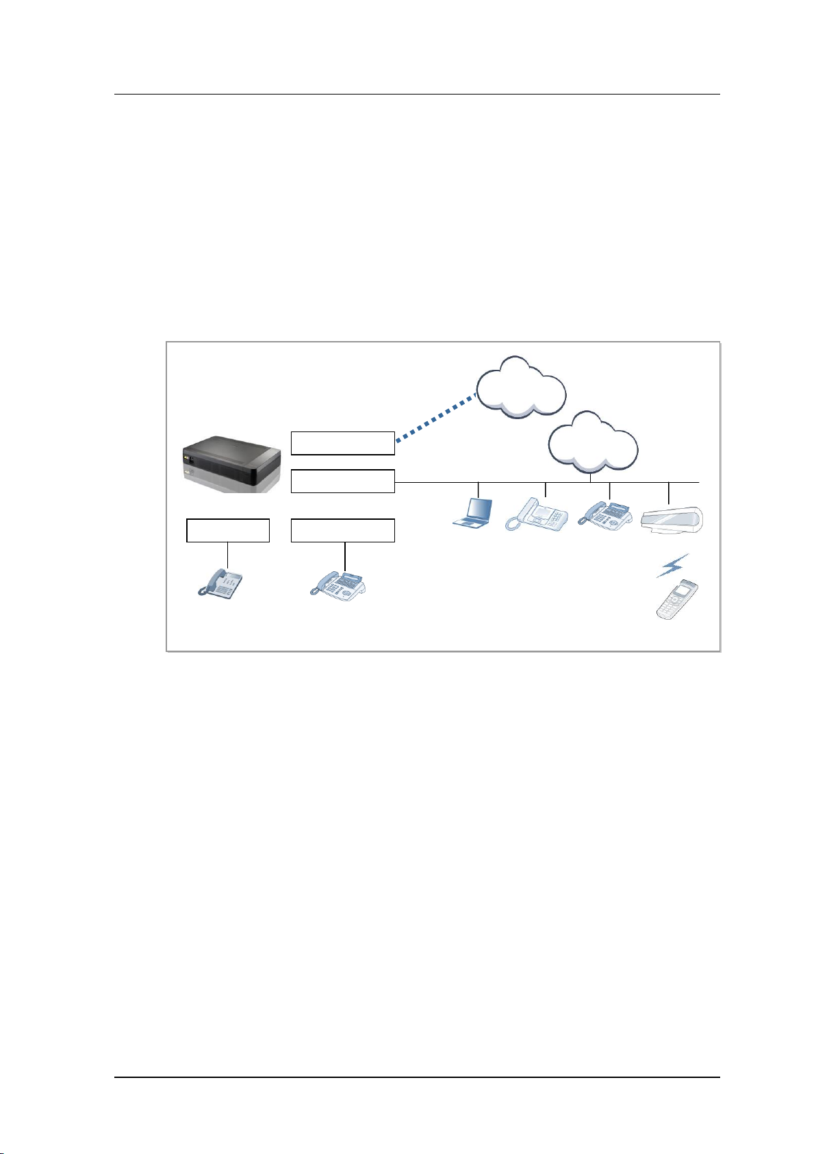
1.1.2 System Architecture
The OfficeServ 7070 is composed of the basic cabinet, to be installed on a wall, and the
OfficeServ Feature server, to be installed in an external Linux server. The main part (Basic
Main Processor, Main Block) of the BMP board, which is the main control block, is
installed within the basic cabinet to manage the overall operations of the OfficeServ 7070
and perform the switching, signal processing, and terminal management functions.
In addition, the B8S part (Basic Main Processor, 8SLI Block) and E8S board (Extended
8SLI Board) are designed to allow the user to mount various option boards onto them.
The service configuration diagram of OfficeServ 7070 system is shown in the figure below:
Figure 1.1 Configuration of OfficeServ 7070 Service
Voice Trunk Part
The voice trunk part is composed of digital and analog trunks.
The PRI Module (PRM) provides the Primary Rate Interface (PRI) digital trunk function,
sending and receiving voices through a trunk and transmitting 64 kbps data packets per
channel. The 2BRM Module (2BRM) provides the Basic Rate Interface (BRI) digital trunk
function for T0 and S0 interfaces. The 4-Port Trunk Module (4TRM) provides the Polarity
Reverse Signal (PRS) and Caller ID (CID) Path functions within a board by default.
© SAMSUNG Electronics Co., Ltd.
1-3
Page 14
CHAPTER 1. Ошибка! Используйте вкладку "Главная" для применения 제목 1 к тексту, который должен здесь
отображаться.
Voice Station Part
The voice station part is composed of the Digital Line Interface (DLI), which is a digital
station, and the Subscriber Line Interface (SLI), which is an analog station, to provide
voice services. Depending on the number of ports and the combination of stations, multiple
station boards can be installed. A 4DLM board is used for a digital station and a 4SL2
board an analog station.
Board Abbreviation description
- BMP (MAIN): Basic Main Processor Board (Main)
- BMP (B8S): Basic Main Processor Board (Basic 8SLI)
- E8S: Extended 8 Port SLI Board
- PRM: PRI ISDN interface Module
- 4DLM: 4 Port DLI Module
- 4TRM: 4 Port Trunk Module
- 4SL2: 4 Port SLI Module
- 2BRM: BRI ISDN interface Module
Voice Application Service Part
The voice application module is composed of the Voice over Internet Protocol (VoIP),
which transmits voices to the data network, and the Wireless Local Area Network (WLAN),
which transmits voices wirelessly. The Media Gateway Interface (MGI) refers to the
application that converts voices to data, thus providing the VoIP function. The MGI is
supported by the processor by default without requiring any additional module.
Application Configuration
The OfficeServ 7070 has a commercial Linux platform server outside the cabinet and
provides the following application software. In contrast, OfficeServ Solution and
OfficeServ Admin are installed on a separate server.
SIP server
OfficeServ Solution (CTI, OfficeServ Operator)
OfficeServ Admin (Web Management, OfficeServ EasySet, System Manager)
1-4
© SAMSUNG Electronics Co., Ltd.
Page 15

OfficeServ 7070 System Description/Ed.02OfficeServ 7070 System Description/Ed.02
1.2 Interfaces between VoIP Components
OfficeServ 7070 provides various VoIP interfaces as follows:
VoIP Networking
SIP VoIP Gateway
SIP Server
System SIP UA (User Agent)
IP Telephone
Standard SIP Telephone
In view of signal processing, the interface interworking standards between VoIP components
are as follows:
Proprietary TCP Inter Process Communication (IPC)
SIP UA-to-UA
UA-to-Server
1.3 Programming
The Man Machine Communication (MMC) program can change the data value used for the
system operation program. The MMC program is categorized into three levels, which are
technician, operator, and subscriber. Depending on these levels, some MMCs can be
programmed by the subscribers while some MMCs cannot.
A password is required for technician level programming or operator level programming;
however, a password is not required for subscriber level programming.
Technician-Level Programming
All programs are programmable.
Programming can be made in any stations in OfficeServ system, but the programming can
be made only in a station at the same time.
Operator Level Program
The operator can program only the program specified in ‘Specification of Program 802
Operator Program Range’ by a technician. Programming can be made in any stations in the
tenant group, but the programming can be only made in a station at the same time.
Subscriber Level Program
Only subscriber programs are programmable.
© SAMSUNG Electronics Co., Ltd.
1-5
Page 16

CHAPTER 1. Ошибка! Используйте вкладку "Главная" для применения 제목 1 к тексту, который должен здесь
This page is intentionally left blank.
отображаться.
1-6
© SAMSUNG Electronics Co., Ltd.
Page 17

OfficeServ 7070 System Description
CHAPTER 2. Hardware of OfficeServ
7070
This chapter introduces the hardware features, cabinet configuration, and board functions
and configuration of OfficeServ 7070 system. In addition, this chapter describes terminals,
wireless LAN equipment, and additional equipment available in OfficeServ 7070 system.
2.1 Features of Hardware
The H/W of OfficeServ 7070 has the following features:
Reliability
The materials and parts used for OfficeServ 7070 hardware are robust and satisfy the
mechanical and electric features required for communication systems.
The cabinet of OfficeServ 7070 complies with the industrial standards and is molded
plastics with flame retardant materials.
OfficeServ 7070 hardware does not generate poisonous or corrosive gas, which might
be harmful for human bodies or affect the system operation.
OfficeServ 7070 hardware has a failure-tolerance to protect the system from the
damage caused by over-voltage.
OfficeServ 7070 hardware is designed considering EMI characteristics.
Maintenance
OfficeServ 7070 hardware is designed to be maintained with ease and safety.
The OfficeServ 7070 is designed to be suitable for wall mounting.
Because the ports connected to the external are located in the front panel, the installation
and maintenance engineers can connect the cables conveniently.
There is a Light Emitting Diode (LED) at the front of each module indicating its
operation status and fault status, helping the operator to identify the status of the
system easily.
The electronic devices are designed not to be damaged by the external environment
during installation or maintenance.
© SAMSUNG Electronics Co., Ltd.
2-1
Page 18

CHAPTER 2. Ошибка! Используйте вкладку "Главная" для применения 제목 1 к тексту, который должен здесь
отображаться.
Fire Resistance and Heat Processing
OfficeServ 7070 hardware is made of fire-resistant materials and parts to protect the
hardware from fire. OfficeServ 7070 hardware is designed not to affect system
performance due to heat generated from inside of the system.
A specific heat-generated part of the hardware is blocked in order not to affect
temperature-sensitive components.
The parts installed into the modules are located on the basis of heat distribution.
A 60 mm cooling fan is installed, which makes the internal air flow out of the system.
2-2
© SAMSUNG Electronics Co., Ltd.
Page 19
OfficeServ 7070 System Description/Ed.02OfficeServ 7070 System Description/Ed.02
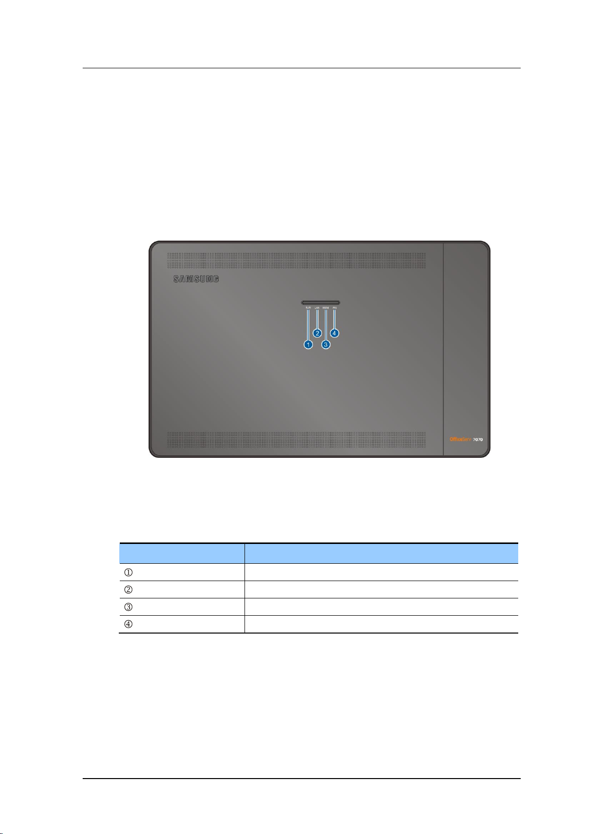
Part
Function
RUN LED
CPU operation status
LAN LED
LAN operation status
MEM LED
CPU access status of Flash Memory
PRI LED
Port status
2.2 Cabinet Configuration
2.2.1 Cabinet View
The OfficeServ 7070 is installed on a wall. The system has a single control part (BMP).
Various subscriber option boards are mounted onto the BMP (MAIN part), BMP (B8S part)
and E8S. The following sections show the appearance of the OfficeServ 7070 system
cabinet.
OfficeServ 7070 top view
Figure 2.1 OfficeServ 7070 Top View
The descriptions about each part are listed in the table below.
Table 2.1 Parts on the top of OfficeServ 7070
© SAMSUNG Electronics Co., Ltd.
2-3
Page 20
CHAPTER 2. Ошибка! Используйте вкладку "Главная" для применения 제목 1 к тексту, который должен здесь
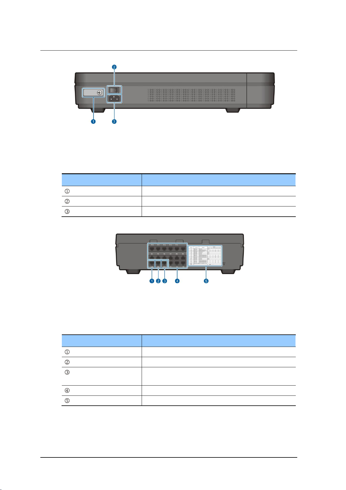
Part
Function
Ground Lug
Ground lug for system communications
Power Switch
Switch to turn the OfficeServ 7070 on/off
Power Connector
Connector to use when connecting to the power cable
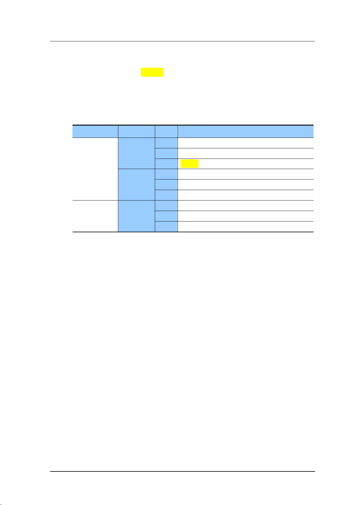
Part
Function
LAN
LAN port
SIO
Debugging port
MISC
Connector used to connect to an external audio device,
broadcasting device, or shared bell, etc.
P1~P14
General-purpose ports
Installation Record Label
Label to record the installed boards on.
отображаться.
OfficeServ 7070 Side view
Figure 2.2 OfficeServ 7070 side view-1
The descriptions about each part are listed in the table below.
Table 2.2 Parts on the side of OfficeServ 7070-1
Figure 2.3 OfficeServ 7070 side view -2
The descriptions about each part are listed in the table below.
Table 2.3 Parts on the side of OfficeServ 7070-2
2-4
© SAMSUNG Electronics Co., Ltd.
Page 21
OfficeServ 7070 System Description/Ed.02OfficeServ 7070 System Description/Ed.02
Cabinet
Module
Slot
Mountable Board
Basic Cabinet
BMP
(MAIN Part)
LOC1
PRM, 4DLM, 4SL2
LOC2
4DLM, 4SL2
LOC3
Modem
BMP
(B8S Part)
LOC1
4TRM, 4DLM, 4SL2, 2BRM
LOC2
4TRM, 4DLM, 4SL2, 2BRM
LOC3
4TRM, 4DLM, 4SL2, 2BRM
Optional Cabinet
E8S
LOC1
4TRM, 4DLM, 4SL2, 2BRM
LOC2
4TRM, 4DLM, 4SL2, 2BRM
LOC3
4TRM, 4DLM, 4SL2, 2BRM
2.2.2 Slot Configuration
The user can mount up to three (3) option boards on the BMP board (MAIN part), three (3)
on the BMP board (B8S part), and three (3) on the E8S board. The option boards that can
be mounted within the OfficeServ 7070 depending on its configuration are listed in the
table below.
Table 2.4 Mountable Boards for Different Slots
© SAMSUNG Electronics Co., Ltd.
2-5
Page 22
CHAPTER 2. Ошибка! Используйте вкладку "Главная" для применения 제목 1 к тексту, который должен здесь
Function
Board
Main Control Part
BMP: Controls the overall system.
Voice Trunk
PRM (for PRI lines), 4TRM (for analog trunks) , 2BRM (for BRI Lines)
Voice Station
4SL2 (for regular phone lines), 4DLM (for digital phone lines), E8S
Data
Modem (optional)
Voice Application
None (Embedded in the system. Controlled by the software.)
Power and Fan
PSU and Fan (Shipped with installed by default)
отображаться.
2.3 Boards by Functions
OfficeServ7070 has Base board and eight slots to mount daughter board. Each slot can
mount the daughter boards that can perform the following function depending on the
configuration type of OfficeServ 7070.
Table 2.5 Boards by Functions
2.3.1 Control Board
The Basic Main Processor (BMP) board is composed of the MAIN part and B8S part.
The main control block of the system is located in the MAIN part. The subscriber block is
located in the B8S part.
2.3.1.1 BMP (MAIN Part)
The BMP (MAIN part) is the control board that controls the main functions of the
OfficeServ 7070 and is installed in the system by default. It performs the voice switching,
signal processing, subscriber terminal management, VoIP processing, and VM/AA
processing functions, etc. In addition, it performs the system booting and data management
functions and directly controls various option boards. The BMP (MAIN part) runs various
applications through the LAN interface. The connector (RJ45) for physical Ethernet
connection is provided from the LAN port installed on the right side of the system.
Main Functions
The BMP (MAIN part) provides the following functions:
Runs various applications through the LAN interface.
VM/AA processing
Controls the secondary storage device (NAND memory).
Provides a Universal Asynchronous Receiver and Transmitter (UART) port
Internal/External Music On Hold (MOH), loud/common bell
Sets and displays the time.
Codec processing (MGI/VM/AA)
Time Switch function
2-6
© SAMSUNG Electronics Co., Ltd.
Page 23

OfficeServ 7070 System Description/Ed.02OfficeServ 7070 System Description/Ed.02
Categories
Names
Standards
CPU
Processor
M82511 (Dual Core)
System Clock
375 MHz
Package
484 Ball FPBGA
SDRAM (For Program and Data)
Capacity
128 MB (32 MB × 4 EA)
Width of Data Bus
32 Bit
NAND (For Program, Db/Voice, Backup)
Capacity
1 GB (K9G8G08U0A)
Width of Data Bus
8 bit
Flash ROM (For Booting)
Capacity
0.5 MB (SST39VF040)
Width of Data Bus
8 bit
Time Switch
Device
STC9604
Basic Switch
256 × 256 Channel
Width of Data Bus
8 Bit
RTC
Device
RTC8564
Back UP Time
10 Days
Interface
I2C
EEPROM (Save IP/MAC Address)
Capacity
2 Kbit (AT24C02N)
Interface
I2C
LAN
Physical Layer
IEEE802.3
Speed
100Mbps Only
Port
1 EA
UART
Type
Async, 8Bit + 1Start + 1Stop
Speed
38.4Kbps
Etc.
External MOH Port
1 EA
External Broadcast
1 EA
Dry Contact
2 EA
Subscriber Port
DLI
4 Port
Option
LOC1
PRM, 4DLM, 4SL2
LOC2
4DLM, 4SL2
LOC3
-
Option board
The BMP (MAIN part) has three (3) slots where option boards can be mounted.
A trunk board (PRM) or subscriber connection board (4DLM, 4SL2) is mounted into LOC1
(slot 1) and LOC2 (slot 2). A Modem board is mounted into LOC3 (slot 3).
Specification
The specification of BMP board is as follows:
Table 2.6 BMP Specification
© SAMSUNG Electronics Co., Ltd.
2-7
Page 24
CHAPTER 2. Ошибка! Используйте вкладку "Главная" для применения 제목 1 к тексту, который должен здесь
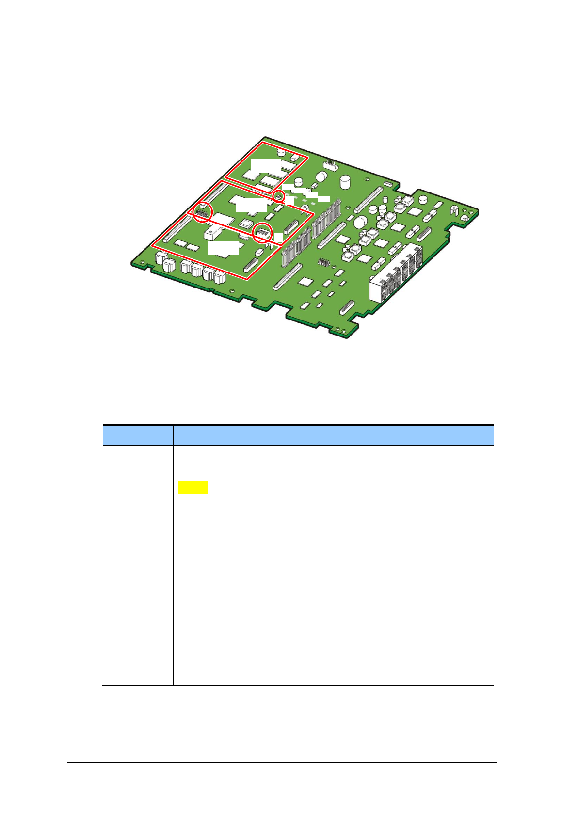
Location
Description
LOC1
An option board is mounted: RPM, 4DLM, 4SL2
LOC2
An option board is mounted: 4DLM, 4SL2
LOC3
Modem
RUN LED
Indicates the operation status of the system.
- Red: The system is booting.
- Green blinking: The system is operating normally.
LAN LED
Indicates the operation status of the LAN of the system.
- Indicates data sending and receiving are proceeding through the Ethernet port.
MEM LED
Indicates whether or not the NAND memory is being accessed.
- Off: The NAND memory is not being accessed.
- Blinking: The NAND memory is being accessed.
PRI LED
Indicates whether the PRM board is mounted and operating.
- Off: No PRM board is mounted.
- On: A PRM board is mounted but no line is connected.
- Blinking: A PRM board is mounted and is operating normally with an actual line
connected.
LOC 1
LOC 2
LOC 3
J9
S1
RUN
LAN
MEM
PRI
S2
отображаться.
Board View
The appearance of the BMP (MAIN part) is as follows:
Figure 2.4 BMP (MAIN Part)
The functions of the parts of the BMP (MAIN part) are listed in the table below:
Table 2.7 BMP (MAIN Part) Configuration
2-8
© SAMSUNG Electronics Co., Ltd.
Page 25

OfficeServ 7070 System Description/Ed.02OfficeServ 7070 System Description/Ed.02
Location
Description
S1 Switch
Determines the system options.
S2 Switch
- The Reset button for the system.
- There are two Reset buttons for the system, the S1 switch within the BMP
(MAIN part) board, and the ‘RST’ button within the duct at the left of the
system.
- While the system is operating, do not remove the system cover. Instead
remove the duct, then use the ‘RST’ button.
- Hold down the button quickly for less than seven (7) seconds to just restart the
system. Hold it down for more than seven (7) seconds to restart the system
with the database reset completely.
J9
Port for CPLD upgrading
Table 2.7 BMP (MAIN Part) Configuration (Continued)
Detail Function
The detailed functions of the BMP (MAIN part) board are as follows:
Provides a LAN interface (test port).
MII (Media Independent Interface) Interface
UART (Universal Asynchronous Receiver and Transmitter)
Provides an SIO port.
The SIO port can be used by connecting a cable to the RJ45 connector printed with
‘SIO’ at the left side of the system. Its speed is 38400 bps. The SIO port is used when
the user wants to know the operation status of the system or change the operation
mode of the system.
Conference, caller information, multiple frequencies detection, and door phone control
functions
Internal/External Music On Hold (MOH), loud/common bell
© SAMSUNG Electronics Co., Ltd.
2-9
Page 26

CHAPTER 2. Ошибка! Используйте вкладку "Главная" для применения 제목 1 к тексту, который должен здесь
отображаться.
2.3.1.2 BMP (B8S Part)
The BMP (B8S part) board supports all eight (8) analog station ports and four (4) analog
trunk ports at the same time. Moreover it has a line connection part for the OfficeServ 7070
system.
It also supports a space where three option boards can be mounted.
Key Functions
The key functions of the BMP (B8S part) voice board are as follows:
20 Hz ring generation
DTMF/Dial pulse detection
On/Off-hook detection
Tone generation
Line connection part
Supports the four (4) port ATRK
Supports the two (2) ports for dry contact
Supports a PFT port
Supports the system reset port
Specification
The specification of the BMP (B8S part) voice board is as follows:
Eight (8) analog station ports
Four (4) analog trunk ports
Two (2) analog TW trunk ports
Provides the system line connection part (equipped with twelve (12) RJ45 connectors)
2-10
© SAMSUNG Electronics Co., Ltd.
Page 27
OfficeServ 7070 System Description/Ed.02OfficeServ 7070 System Description/Ed.02
Port, LED
Description
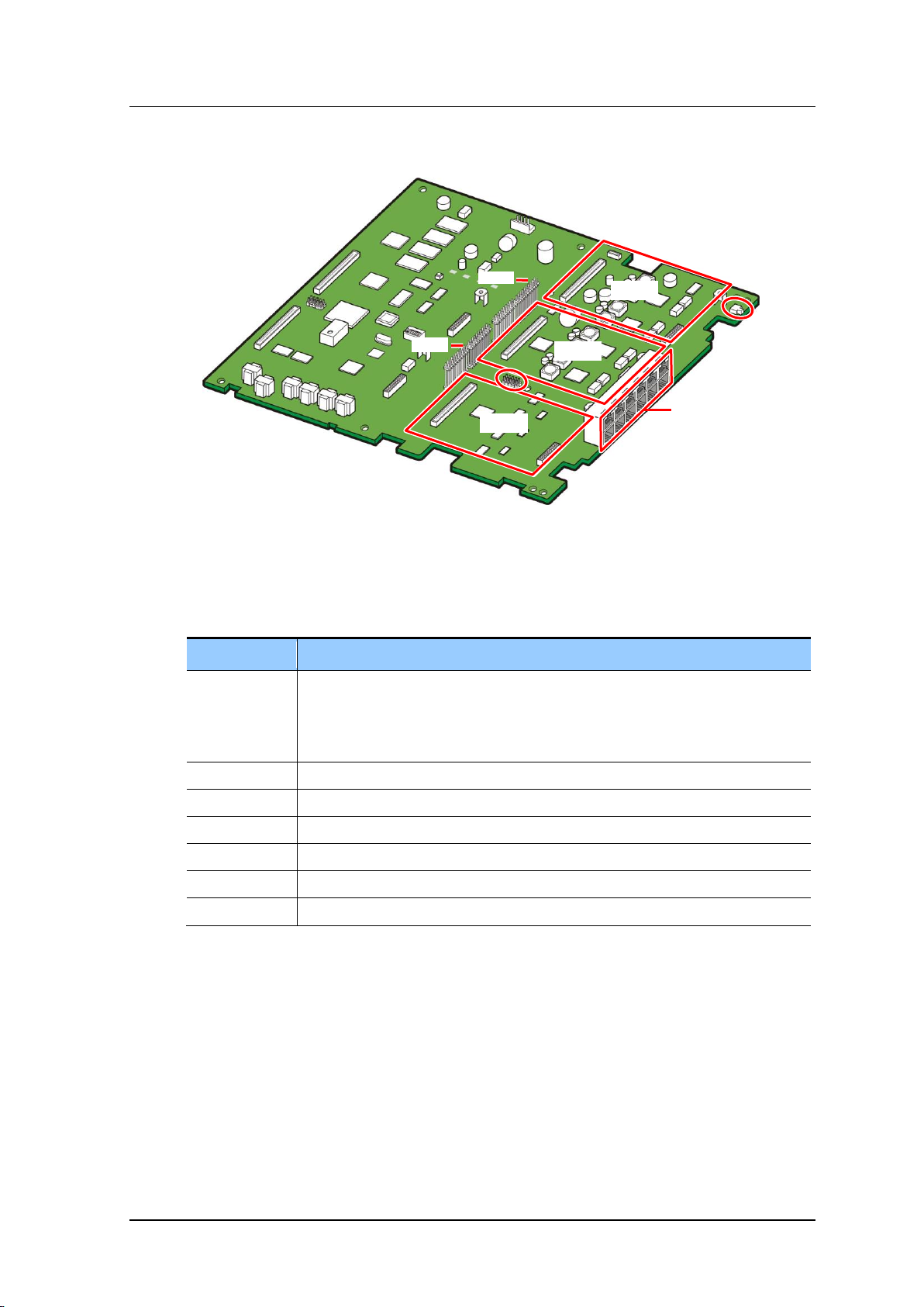
S1000
System reset button
- When held down for less than seven (7) seconds: Just restarts the system.
- When held down for more than seven (7) seconds: Clears the system database
completely and restarts the system.
J1002
Port for CPLD fusing
LOC1
An option board is mounted. (Mountable boards: 4TRM, 4DLM, 4SL2, 2BRM)
LOC2
An option board is mounted. (Mountable boards: 4TRM, 4DLM, 4SL2, 2BRM)
LOC3
An option board is mounted. (Mountable boards: 4TRM, 4DLM, 4SL2, 2BRM)
J1000
Line connection part
P1004, P1007
E8S board connectors
LOC 1
LOC 2
LOC 3
P1004
P1007
J1002
S1000
J1000
Board View
Figure 2.5 BMP (B8S Part)
The functions of the parts of the BMP (B8S part) are listed in the table below:
Table 2.8 BMP (B8S Part) Configuration
© SAMSUNG Electronics Co., Ltd.
2-11
Page 28
CHAPTER 2. Ошибка! Используйте вкладку "Главная" для применения 제목 1 к тексту, который должен здесь
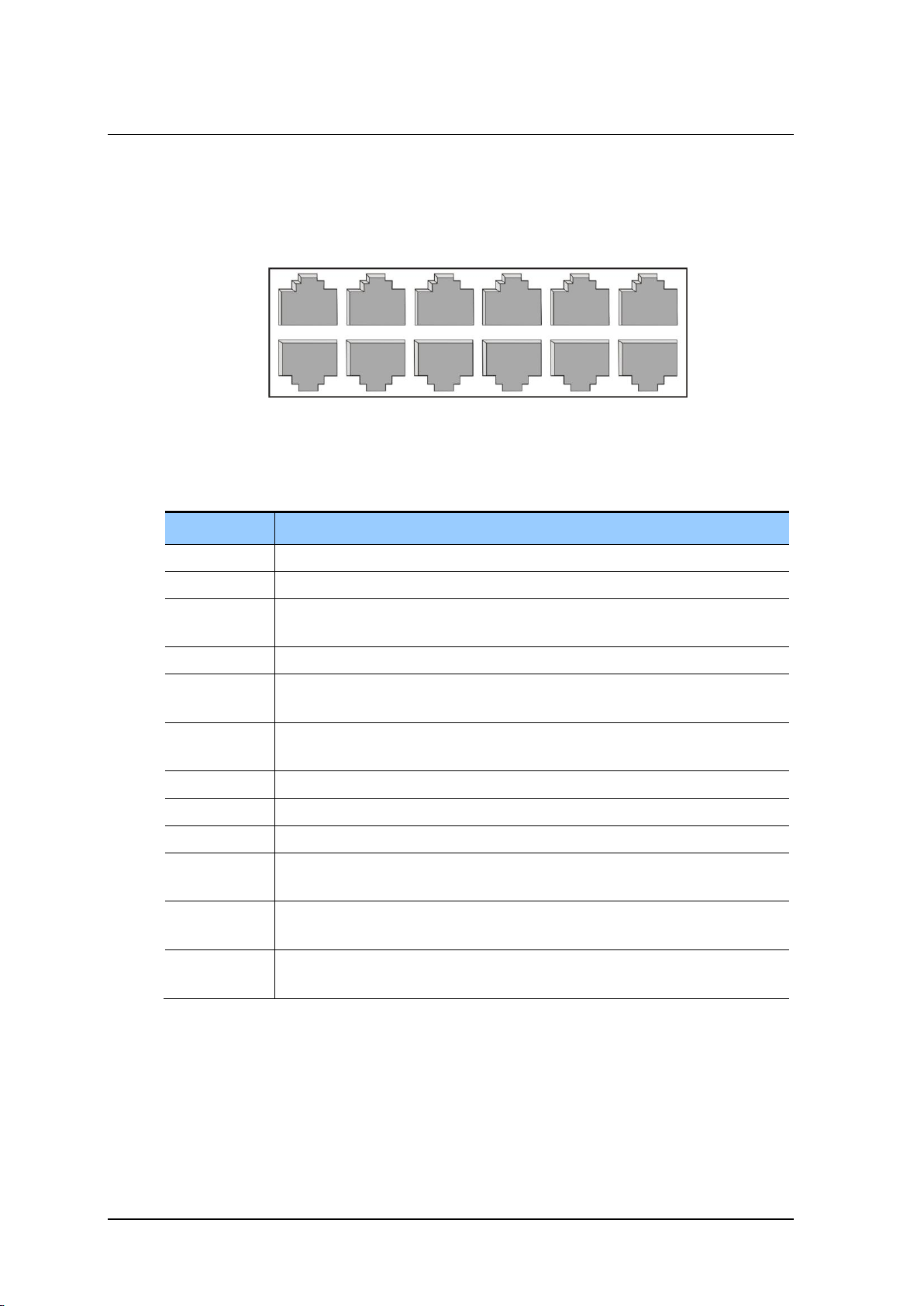
Port
Description
LAN
System LAN port, 100 Mbps. The BMP (MAIN part) supports this function.
SIO
System SIO port
MISC
System MISC ports (A port for an external sound source, a port for external
paging, two (2) ports for dry contact)
P1
Four (4) DLI ports for the BMP (MAIN part)
P2
Line connector for the option board (PRM/4DLM/4SL2) mounted at LOC1 of the
BMP (MAIN part)
P3
Line connector for the option board (4DLM/4SL2) mounted at LOC2 of the BMP
(MAIN part)
P4
Line connector for the BMP (B8S part) ATRK ports (four (4) ports)
P5
Line connector for the BMP (B8S part) 8SLI ports (four (4) ports)
P6
Line connector for the BMP (B8S part) 8SLI ports (four (4) ports)
P7
Line connector for the option board (4TRM/2BRM/4DLM/4SL2) mounted at
LOC1 of the BMP (B8S part)
P8
Line connector for the option board (4TRM/2BRM/4DLM/4SL2) mounted at
LOC2 of the BMP (B8S part)
P9
Line connector for the option board (4TRM/2BRM/4DLM/4SL2) mounted at
LOC3 of the BMP (B8S part)
P4
P5
P6
P7
P8
P9
LAN
SIO
MISC
P1
P2
P3
отображаться.
Line connection part
The BMP (B8S part) has a line connection part which provides the ports for connecting the
system LAN/SIO/MISC lines and subscriber/trunk lines.
Figure 2.6 BMP (B8S Part) Line Connection Part
Table 2.9 BMP (B8S Part) Ports for External Connections
2-12
© SAMSUNG Electronics Co., Ltd.
Page 29

OfficeServ 7070 System Description/Ed.02OfficeServ 7070 System Description/Ed.02
2.3.2 Voice Trunk Board
2.3.2.1 PRM
The PRI Module (PRM) board provides digital trunks. It provides ISDN PRI and the Q-SIG
function as well. It provides voices through a trunk and transmits 64 kbps voice data per channel.
Key Functions
The PRM voice trunk board provides the following functions:
Selecting the PRI signal processing through programming
A resistance circuit satisfying both T1 (100 Ω) and E1 (120 Ω) at the same time
Surge protection safer than the level recommended by International Telecommunication
Union (ITU)
Output port protection through a line monitor
Jitter function meeting both of the ITU-T I.431 and G.703 specifications
Provides the selectable line codec (HDB3, AMI)
Local/Remote loop function
HDLC or Channel Associated Signaling (CAS) through Common Channel Signaling
(CCS)
Specification
The specification of the PRM voice trunk board is as follows:
PRI: 30 channels
© SAMSUNG Electronics Co., Ltd.
2-13
Page 30

CHAPTER 2. Ошибка! Используйте вкладку "Главная" для применения 제목 1 к тексту, который должен здесь
Port, LED
Description
S1
Determines the operation mode of the PRM board.
- Position1: ON-T1
OFF-E1 (*)
- Position2: ON-PRI (*)
OFF-E1/T1
- Position3: ON-24B
OFF-24B+D (*)
- Position4: ON-Network
OFF-User (*)
- (*): Factory default.
- Make sure to use User mode when connecting to the CO. If the user wants to
use two OS7070 systems, make sure to set one system to Network mode and
the other to User mode before connecting them.
S2
PRM board reset button
J1
SIO port
Connect to the J1 port if the user wants to connect SIO directly to the PRM
board.
- Pin 1: Rx (Based on the PRM)
- Pin 2: Tx (Based on the PRM)
- Pin 3: GND
J5
Port for CPLD fusing
LED: LOS
Indicates whether or not a loss of signal has occurred.
- On: A loss of signal has occurred.
- Off: There has not been a loss of signal.
IPC
SYN
LOS
AIS
L2
CLK
S2
J5
S1
J1
отображаться.
Board View
The appearance of the PRM voice trunk board is as follows:
Figure 2.7 PRM Board
The functions of the parts of the PRM board are listed in the table below:
Table 2.10 PRM Board Configuration
2-14
© SAMSUNG Electronics Co., Ltd.
Page 31

OfficeServ 7070 System Description/Ed.02OfficeServ 7070 System Description/Ed.02
Port, LED
Description
LED: AIS
Indicates whether or not a T1/E1 remote alarm has occurred.
- On: A remote alarm has occurred.
- Off: There has not been a remote alarm.
LED: L2
Indicates the operation status of the Layer 2.
- On: The operation of the PRI Layer 2 is normal.
- Off: The operation of the PRI Layer 2 is abnormal.
LED: IPC
Indicates the interoperation status of the upper module.
- On: The interoperation with the BMP is normal.
- Off: The interoperation with the BMP is abnormal.
LED: CLK
Indicates the Master/Slave status.
- On: The synchronization clocks are received from the opposite station.
- Off: The synchronization clocks are used as internal clocks.
LED: SYN
Indicates the frame synchronization status with the opposite exchanger
- On: The frames are synchronized with the opposite exchanger.
- Off: The frames are unsynchronized with the opposite exchanger.
Table 2.10 PRM Board Configuration (Continued)
© SAMSUNG Electronics Co., Ltd.
2-15
Page 32

CHAPTER 2. Ошибка! Используйте вкладку "Главная" для применения 제목 1 к тексту, который должен здесь
отображаться.
2.3.2.2 4TRM
The 4 Port Trunk Module (4TRM) board provides four (4) analog trunk ports. A 4TRM
board provides both of the PRS and CID paths.
Key Functions
The 4TRM voice trunk board provides the following functions:
Incoming ring detection
On/Off-hook detection
Dial pulse transmission
PRS function
CID function
Line monitoring function. This function checks whether or not a line is connected, and
provides the service only if it is connected
Specification
The 4TRM voice trunk board provides four (4) trunk ports.
Board View
The 4TRM board can be mounted as a daughter board on the BMP (B8S part) or E8S
board.
There is no separate line connection part within the 4TRM board. It is connected to an
external line through the RJ45 connector on the line connection part, located at the left
side of the system.
Figure 2.8 4TRM Board
2-16
© SAMSUNG Electronics Co., Ltd.
Page 33

OfficeServ 7070 System Description/Ed.02OfficeServ 7070 System Description/Ed.02
S1
2.3.2.3 2BRM
The 2BRM (BRI ISDN module) board provides two 2B+1D digital trunk ports. This
module is connected to 4 channel ISDN trunk in S0 and T0 interface. In S0 interface do not
support DC power feeding mode.
Key Functions
The 2BRM digital trunk board provides the following functions:
Full duplex 2B+1D S/T interface transceiver based on Consultative Committee on
International Telegraphy and Telephony (CCITT) I.430
Frame conversion between S/T interface and ISDN Oriented Modular(IOM)
Receive timing recovery according to a specific operation mode
D-channel access
Activation and deactivation procedures (automatic wake-up in power-down state)
Specification
The 2BRM digital trunk board provides four B channel and two D channel.
Appearance
The 2BRM board can be mounted as a daughter board on the BMP (B8S part) or E8S
board.
Maximum 3 boards can be mounted in a system.
There is no separate line connection part within the 2BRM board. It is connected to an
external line through the RJ45 connector on the line connection part, located at the
right side of the system.
Switch on of S1 provided a termination 100 ohm for S0 interface.
© SAMSUNG Electronics Co., Ltd.
Figure 2.9 2BRM Board appearance
2-17
Page 34

CHAPTER 2. Ошибка! Используйте вкладку "Главная" для применения 제목 1 к тексту, который должен здесь
Port
Description
P1
100-pin Connector
Connector for connecting a signal line to the base board
J1
Connector for connecting lines to the four (4) ports
P1
J1
отображаться.
2.3.3 Voice Station Board
This section describes the board which provides the station voice service.
2.3.3.1 4SL2
The 4 Port SLI Module 2 (4SL2) board is the module used to process regular phone
connections.
Key Functions
The key functions of the 4SL2 voice station board are as follows:
20 Hz ring generation
Dial Tone Multi Frequency (DTMF)/Dial pulse detection
On/Off-hook detection
Tone generation
Specification
The specification of the 4SL2 voice station board is as follows:
4SL2 board: Four (4) station ports
Board View
2-18
© SAMSUNG Electronics Co., Ltd.
Figure 2.10 4SL2 Board
Table 2.11 4SL2 Board Configuration
Page 35

OfficeServ 7070 System Description/Ed.02OfficeServ 7070 System Description/Ed.02
Port
Description
P1
100-pin Connector
Connector for connecting a signal line to the base board (BMP or E8S)
P2
Connector for connecting lines to the four (4) ports
P1
P2
2.3.3.2 4DLM
The 4 Port DLI Module (4DLM) board provides four (4) digital station ports.
It interoperates with a Samsung digital phone through a station to provide the voice
communication function.
Specification
The specification of the 4DLM voice station board is as follows:
4DLM board: Provides four (4) station ports and 1B+D (a voice channel and a signal
channel)
Board View
The 4DLM board is a daughter board which can be mounted on the BMP (MAIN part),
BMP (B8S part) or E8S board.
Figure 2.11 4DLM Board
Table 2.12 4DLM Board Configuration
© SAMSUNG Electronics Co., Ltd.
2-19
Page 36

CHAPTER 2. Ошибка! Используйте вкладку "Главная" для применения 제목 1 к тексту, который должен здесь
отображаться.
2.3.3.3 E8S
The Extended 8 Port SLI (E8S) board supports eight (8) analog station ports and is used to
extend lines. In addition, it has a line connection part for the OfficeServ 7070 system.
It also supports a space where three option boards can be mounted.
Key functions
The key functions of the E8S voice board are as follows:
20 Hz ring generation
DTMF/Dial pulse detection
On/Off-hook detection
Tone generation
Line connection part
Specification
The specification of the E8S voice board is as follows:
Eight (8) analog station ports
Provides the system line connection part (equipped with five (5) RJ45 connectors)
2-20
© SAMSUNG Electronics Co., Ltd.
Page 37

OfficeServ 7070 System Description/Ed.02OfficeServ 7070 System Description/Ed.02
Port, LED
Description
J700
Port for CPLD fusing
LOC1
An option board is mounted. (Mountable boards: 4TRM, 4DLM, 4SL2, 2BRM)
LOC2
An option board is mounted. (Mountable boards: 4TRM, 4DLM, 4SL2, 2BRM)
LOC3
An option board is mounted. (Mountable boards: 4TRM, 4DLM, 4SL2, 2BRM)
J701
Line connection part
P7, P8, P9, P10
E8S board connectors
LOC 1
LOC 2
LOC 3
J700
J701
P10
P9
P8
P7
Board View
The appearance of the E8S extension board is as follows:
Figure 2.12 E8S Board
Table 2.13 E8S Board Configuration
© SAMSUNG Electronics Co., Ltd.
2-21
Page 38

CHAPTER 2. Ошибка! Используйте вкладку "Главная" для применения 제목 1 к тексту, который должен здесь
Port
Description
P10
Line connector for the E8S Base 8SLI ports (four (4) ports)
P11
Line connector for the E8S Base 8SLI ports (four (4) ports)
P12
Line connector for the option board (4TRM/2BRM/4DLM/4SL2) mounted at
LOC1 of the E8S)
P13
Line connector for the option board (4TRM/2BRM/4DLM/4SL2) mounted at
LOC2 of the E8S)
P14
Line connector for the option board (4TRM/2BRM/4DLM/4SL2) mounted at
LOC3 of the E8S)
P10
P11
P12
P13
P14
отображаться.
Line connection part
The E8S board has the line connection part for connecting subscriber/trunk lines.
Figure 2.13 E8S Line Connection Part
Table 2.14 E8S Ports for External Connections
2.3.4 Data Board
The Modem used in OfficeServ 7070 system should support 2 wire full duplex, can be
shared with the Modem of OfficeServ 7400 system. Modem board is mounted on Loc. 3 of
BMP board. When the board is mounted, be careful of the direction of the connectors.
Modem board is connected to OfficeServ 7070 system through V.24 interface and uses the
Modem chip for central office that PCM highway interface is available. In addition, the
Modem board supports the V.90 protocol. Modem board is controlled through the serial
communication type in OfficeServ 7070 and the command used is standard AT commands.
Key functions
The Modem board has the following functions:
Base board has a 2-Wire Full Duplex Modem and can commonly use it with
OfficeServ 7000 series system. Be careful of the direction of the connectors when
mounting/demounting the board to the BMP board.
The Modem board operates in OfficeServ 7070 via V.24 interface and uses a Modem
chip for Central Office, which can perform Pulse Code Modulation (PCM) highway
interface. In addition, the Modem board supports V.90 protocol. OfficeServ 7070
controls the Modem board via serial communication using standard AT commands.
The main purpose of Modem is a remote DB access through IT(Installation-Tool).
2-22
© SAMSUNG Electronics Co., Ltd.
Page 39

OfficeServ 7070 System Description/Ed.02OfficeServ 7070 System Description/Ed.02
2.4 Station Phones
This section describes the types and features of analog/digital station phones that can be
connected to OfficeServ 7070 system.
2.4.1 Regular Phones
The regular phones used for voice calls are connected to the ports of the BMP (MAIN
Part)/BMP (B8S Part)/E8S/4SL2 module mounted on the Universal slot of the OfficeServ
7070 system.
2.4.2 Digital Phones
Digital phones are used for the transmission of voice calls and data, and are connected to
the ports of BMP (MAIN Part)/BMP (B8S Part)/E8S/4DLM board mounted on the
Universal slot of OfficeServ 7070 system.
2.4.2.1 DS-24SE
The DS-24SE phones have 24 program buttons allowing the user to register the functions
he wants to use and the [Up]/[Down] key allows him to adjust the speaker and receiver
volumes easily.
A speaker is also embedded within it, which can be placed on a desktop or wall.
Figure 2.14 Regular Phone
© SAMSUNG Electronics Co., Ltd.
Figure 2.15 DS-24SE
2-23
Page 40

CHAPTER 2. Ошибка! Используйте вкладку "Главная" для применения 제목 1 к тексту, который должен здесь
отображаться.
2.4.2.2 DS-2000 Series
The DS-2000 series phone has an embedded speaker and program buttons with which the
user can easily register functions. The user can also adjust the speaker and receiver
volumes easily using the [Up]/[Down] key. The user can display 32 characters on the
Liquid Crystal Display (LCD) using the three (3) soft keys and the scroll key.
Figure 2.16 DS-2024E
2.4.2.3 DS-3020S
With the DS-3020S phone, the user can adjust the speaker and receiver volumes easily
using the volume button. And by using the DSS button, the user can also make a call to a
previously saved number. In addition, the phone also has a world clock, calculator, alarm
functions, and many more features.
Figure 2.17 DS-3020S
2-24
© SAMSUNG Electronics Co., Ltd.
Page 41

OfficeServ 7070 System Description/Ed.02OfficeServ 7070 System Description/Ed.02
2.4.2.4 DS-4000 Series
The DS-4000 series phone provides not only the voice call and data transmission functions
but also the advanced functions, such as dual LED button, 2×16 character LCD, and multifunctional display.
Figure 2.18 DS-4028D
2.4.2.5 DS-5000 Series
DS-5012L
The ITP-5012L is a large LCD phone, which allows the users to transmit data, make calls
using a handset/speaker phone, or use the full-duplex speaker phone. In addition, the
Universal Serial Bus (USB) interface (sharable with a cellular phone) is supported and
various functions are provided through the LCD.
The button operation is also more convenient in comparison to other phones. This is
because the navigation buttons, as well as the normal buttons, are provided. The phonebook
function and the call recording function are also provided. For more information on how to
use the DS-5012L phone, refer to the ‘OfficeServ Digital phone DS-5012L User Guide’.
Figure 2.19 DS-5012L
Connecting DS-5012L Phones to the System
The user can connect up to twelve DS-5012L phones to the OfficeServ 7070.
Install a 4DLM board into an expansion slot of the BMP (MAIN part) itself, BMP
(B8S part) or E8S board.
© SAMSUNG Electronics Co., Ltd.
2-25
Page 42

CHAPTER 2. Ошибка! Используйте вкладку "Главная" для применения 제목 1 к тексту, который должен здесь
отображаться.
DS-5014D/5021D/5038D
DS-5014D/5021D/5038D phones are two-line LCD digital phones and have 14, 21, or 38
program buttons that allow the subscribers to register their desired functions and make calls
by using a handset/speaker phone.
DS-5014D/5021D phones have the navigation buttons that allow the users to easily use the phone
functions (searching phone numbers by recent calling number, recent called number and name,
setting call forwarding and an alarm, and searching speed dials) and connect with the KDBD/S/F devices. For detailed information on the phones, refer to ‘User’s Guide for
OfficeServ Digital Phones, DS-5014D/5021D/5038D’.
Figure 2.20 DS-5014D Figure 2.21 DS-5021D
Figure 2.22 DS-5038D
2-26
© SAMSUNG Electronics Co., Ltd.
Page 43

OfficeServ 7070 System Description/Ed.02OfficeServ 7070 System Description/Ed.02
2.4.3 IP Phones
The IP phones are a new concept of Internet phones that use an IP address to send/receive
voice or data. The IP phones use the installed data network lines to make voice
communications and do not need telephone lines. The IP phones can be connected with the
devices such as a switching hub and are connected with other digital phones through LAN
ports of OfficeServ 7070.
2.4.3.1 ITP-5100 Series
ITP-5112L
The ITP-5112L is a large LCD phone, which allows the users to transmit data, make calls
using a handset/speaker phone, or use the full-duplex speaker phone. A variety of functions
are provided through the large LCD. The buttons of the ITP-5112L are convenient to
operate because the ITP-5012L phone has navigation buttons as well as regular buttons.
Also, it provides the functions of a phone book and call recording.
Figure 2.23 ITP-5112L
ITP-5114D/5121D
The ITP-5114D/5121D phone is a two line LCD digital phone and has 14 or 21 programmable
buttons that allow the subscribers to register their desired functions and make calls by using
a handset/speaker phone.
The ITP-5114D/5121D phone has the navigation buttons that allow the users to easily use the
phone functions (recent called number, recent connected number, search phone numbers by name,
call forwarding, search abbreviated numbers, or alarm setting).
Figure 2.24 ITP-5114D Figure 2.25 ITP-5121D
© SAMSUNG Electronics Co., Ltd.
2-27
Page 44

CHAPTER 2. Ошибка! Используйте вкладку "Главная" для применения 제목 1 к тексту, который должен здесь
AOM Type
Connectable Phone
DS-5064B AOM
DS-5000 series digital phone
DS-4014 AOM
DS-4000 series digital phone
DS-4064 AOM
DS-24SE AOM
DS-24SE digital phone
DS-2024E AOM
DS-2000 series digital phone
DS-3020S AOM
DS-3000 series digital phone
отображаться.
2.4.4 Add On Module
The Add On Module (AOM) is the extended module type digital terminal where the
program buttons and LEDs in a digital phone are expanded. Desired functions can be
specified into the buttons on the AOM. For information on the figure of each AOM or how
to connect the AOM, refer to the User’s Guide about the AOM.
Figure 2.26 DS-5064B
The AOMs available in OfficeServ 7070 system and phones that can be connected with the
AOM are as follows.
Table 2.15 AOM Type
2-28
© SAMSUNG Electronics Co., Ltd.
Page 45

OfficeServ 7070 System Description/Ed.02OfficeServ 7070 System Description/Ed.02
2.4.5 Door Phone Interface Module
Door Phone Interface Module (DPIM) is the module that connects door phones and door
open/close devices to OfficeServ 7070. The line port of the door phone interface device is
connected to the DLI port of OfficeServ 7070 system. The door box port of the door phone
interface device is connected to the line port of the door phone.
Figure 2.27 DPIM
Reference
For information on how to connect terminals such as a door phone interface
device, refer to ‘OfficeServ 7070 Installation Manual’.
© SAMSUNG Electronics Co., Ltd.
2-29
Page 46

CHAPTER 2. Ошибка! Используйте вкладку "Главная" для применения 제목 1 к тексту, который должен здесь
отображаться.
2.5 Wireless LAN Device
This section describes the wireless LAN BTS and mobile stations that can be connected
with OfficeServ 7070 system.
2.5.1 Wireless LAN Base Station (DUAL Band AP)
An example of the wireless LAN APs that can interoperate with the OfficeServ 7070 is the
SMT-R2000. The SMT-R2000 is a dual band AP that supports the wireless LAN service of
both of 2.4 GHz (IEEE 802.11b/g) and 5 GHz (IEEE 802.11a) bandwidths simultaneously.
It supports the IEEE 802.11e, a wireless LAN QoS standard, and supports all of WEP,
WPA1 and WPA2 (IEEE 802.11i) for wireless LAN security. The power for this can be
supplied using the Power over Ethernet (PoE) switch supporting the IEEE 802.3af.
2.5.2 Mobile Phone
The SMT-W5100, which is a local wireless mobile station, uses the wireless LAN of
IEEE802.11a/b/g to allow the users to make voice calls. The SMT-W5100 supports handover when moving between the APs (SMT-R2000) and can use data terminals such as
laptops that enable the wireless LAN in the same place. The SMT-W5100 performs the
message service functions supported by the OfficeServ 7070 system as well.
Figure 2.28 SMT-R2000
Figure 2.29 SMT-W5100
2-30
© SAMSUNG Electronics Co., Ltd.
Page 47

OfficeServ 7070 System Description/Ed.02OfficeServ 7070 System Description/Ed.02
2.6 Additional Devices
This section describes the types and features of devices that can be connected optionally
when OfficeServ 7070 is installed.
2.6.1 On Hold/Background Sound Source
OfficeServ 7070 is connected with cassettes or radios in addition to the basic tone provided
by the system or internal sound source to allow subscribers to listen to melodies other than
ones specified to the subscribers. The devices such as the cassettes or radios are called on
hold/background sound source.
The on hold/background sound source is mainly used for on hold tone, background music,
or announcement and can be used by being connected with the external sound source
devices below:
FM radio
CD player
Cassette tape recorder
Output Resistance
The speaker output resistance of FM radios, CD players, or cassette recorders is
normally 8 Ω or 16 Ω.
2.6.2 External Broadcasting Units
OfficeServ 7070 is connected with external broadcasting units such as amplifiers or speakers
for consumers instead of internal speakers. These external broadcasting units are connected
through the MISC ports of BMP (B8S Part).
2.6.3 Loud Bell
The Loud Bell allows the users to listen to ring signals from outside, and amplifiers or
external speakers are used for the Loud Bell. The Loud Bell is connected via the MISC port
of BMP (B8S Part). Two ports are supported. These are used to support an external
broadcasting or auxiliary call device through the MMC.
2.6.4 Common Bell
The Common Bell is a ring that can be specified when a station group is set. Once a station
in a group rings, other stations in the group ring. The Common Bell is connected via the
MISC port of Base board
© SAMSUNG Electronics Co., Ltd.
2-31
Page 48

CHAPTER 2. Ошибка! Используйте вкладку "Главная" для применения 제목 1 к тексту, который должен здесь
отображаться.
2.6.5 WEB Management
The Web management is the software for the installation/maintenance of OfficeServ 7070.
The functions for controlling the system database are implemented in the form of menus in
the Web management; thus, the WEB management is convenient to use when the system
data are displayed or changed.
2.6.6 SMDR
The Station Message Detail Recording (SMDR) manages entire calling data such as calls
between station subscribers connected with OfficeServ 7070 as well as local/long
distance/international calls. OfficeServ 7070 provides calling data. Connect the SMDR
printer or SMDR computer with OfficeServ 7070 to use the SMDR data provided by
OfficeServ 7070 system.
The SMDR printer can display call history received from OfficeServ 7070, however
does not display data other than the call history (i.e., toll data).
The SMDR computer displays call history received from OfficeServ 7070 and calculates
toll using the SMDR software based on the call history. Accordingly, the SMDR
computer allows the users to use data more efficiently than the SMDR printer.
2.6.7 CTI
The Computer Telephony Integration (CTI) is the integrated system of computer and
telephony. That is, the CTI interworks computers with PBXs so that the computers make
use of the PBXs as computer resources and the PBXs share the computer resources.
The CTI provides the operator with convenience and reduced costs and the customers with
enhanced services and reduced call processing time.
Particularly, the CTI call center system configures data on the customers into databases.
Based on the databases, the call center can consult with the customers one to one.
The CTI integrates communication, computers, and database based on phones as a basic
medium to allow the users to perform marketing using computers such as customer-focused
telemarketing.
OfficeServ 7070 supports the standard Telephony Application Programming Interface (TAPI),
which is implemented in a client/server environment and controls third party calls.
2-32
© SAMSUNG Electronics Co., Ltd.
Page 49

OfficeServ 7070 System Description
Item
Category
Number by type
Sub Total
Total number
Trunk
Analog trunk
28
58
90
PRI trunk
30
BRI trunk
24
SIP trunk
8
8
SPNet port
8
Station
Regular phone
48
52
Digital phone
36
Samsung IP phone
32
Samsung WiFi phone
SIP phone
Others
AA port (G.711)
4 4 4
VM port (G.711)
4 4 4
MGI port (G.729)
8 8 8
Mobex 8 8
8
CHAPTER 3. Specification of
OfficeServ 7070
This chapter describes the capacity of OfficeServ 7070, various signal specification, power
specification, rings and tones, compatible boards and terminals, and equipment
specifications.
3.1 System Capacity
Up to 58 lines can be installed and operated in OfficeServ 7070 system, and the line ratio
of the station and trunk line can be adjusted within the capacity depending on the users’
needs. Table below shows the maximum line capacity of OfficeServ 7070.
Table 3.1 OfficeServ 7070 Line Capacity
© SAMSUNG Electronics Co., Ltd.
3-1
Page 50

CHAPTER 3. Ошибка! Используйте вкладку "Главная" для применения 제목 1 к тексту, который должен здесь
Module
Maximum Line Capacity
Basic cabinet
- Four (4) DLI ports: BMP (MAIN part) base (default installation board)
- Eight (8) SLI ports: BMP (B8S part) base
- Four (4) ATRK ports: BMP (B8S part) base
- PRM: One (1) is installed at the BMP (MAIN part) LOC1.
- 4DLM: Up to five (5) can be installed on the BMP (MAIN part) and
BMP (B8S part).
- 4SL2: Up to five (5) can be installed on the BMP (MAIN part) and
BMP (B8S part).
- 4TRM: Up to three (3) can be installed on the BMP (B8S part).
E8S
- 4TRM: Up to three (3) can be installed on the BMP (B8S part).
- Eight (8) SLI ports: E8S Base
- 4DLM: Up to three (3) can be installed.
- 4SL2: Up to three (3) can be installed.
- 4TRM: Up to three (3) can be installed.
PRM
PRI 30 lines
4TRM
ATRK 4Port
4DLM
DLI 4Port
4SL2
SLI 4Port
2BRM
BRI 4 lines
System Configuration
Analog
Digital
LOOP TRK
T1 TRK
E1 TRK
PRI TRK
Basic cabinet
16 - -
E1: 30
Basic cabinet +E8S
28 - -
E1: 30
System Configuration
Regular Phones
Digital Phones
Basic cabinet
28
24
Basic cabinet +E8S
48
36
отображаться.
Table 3.2 OfficeServ 7070 System Capacity
3.1.1 Trunk Line Capacity
The maximum trunk line capacity of OfficeServ 7070 based on its configuration is shown
in the table below:
Table 3.3 Trunk Line Capacity
3.1.2 Station (Subscriber) Line Capacity
The maximum station line capacity for regular phones and digital phones in OfficeServ
7070 based on its configuration is shown in the table below:
Table 3.4 Station Line Capacity
3-2
© SAMSUNG Electronics Co., Ltd.
Page 51

OfficeServ 7070 System Description/Ed.02OfficeServ 7070 System Description/Ed.02
Item
Slot
Channel
Basic cabinet
BMP (MAIN Part) Slot1, 2
BMP (B8S Part) Slot 1, 2, 3
64
BMP (B8S Part) Slot 1, 2, 3
64
Expansion cabinet
E8S Slot 1, 2, 3
64
CID Receiver
For Basic cabinet
8
DTMF Receiver
For Basic cabinet
8
3.1.3 Channel Capacity
The number of channels and the numbers of CID and DTMF receiver channels are shown
in the table below:
Table 3.5 Channel Capacity of Slot
© SAMSUNG Electronics Co., Ltd.
3-3
Page 52

CHAPTER 3. Ошибка! Используйте вкладку "Главная" для применения 제목 1 к тексту, который должен здесь
Category
Specification
Transmission speed
2048 Kbits/s ±50 ppm
Code
HDB3 (High Density Bipolar of Order 3)
Pulse type
Regular square wave: When indicating all valid signals,
comply with the mask (I.403) regardless of the codes.
Nominal and pulse
244 ns
Transmission media
A pair of twisted lines
Load resistance
120 Ω
Indicated (pulse) nominal peak voltage
3.00 V
Blank (No Pulse) Peak Voltage
0 ±0.300 V
OPEN END
CLOSED END
X
T R T R GND
-48 VDC
(C.O.)
Key Telephone
отображаться.
3.2 Electrical Specification
3.2.1 Signal Specification
The signal processing protocol means the methods for connecting signals between the trunk
lines, stations and system, and also means the method of providing the status information.
3.2.1.1 Trunk Line Signaling
Loop Start
In processing loop start signals, the on-hook and the off-hook statuses are controlled by the
flow of electric current. The loop is a closed loop trunk circuit or a standard 2500-type set
loop.
Figure 3.1 Trunk Line Loop Start Signaling
Characteristics of the ISDN Interface Transmission
The electrical characteristics of the ISDN (PRI) interface comply with the ITU I.430 and
ETS 300 012 standards.
Table 3.6 Electrical Characteristics of the PRI Trunk Line
3-4
© SAMSUNG Electronics Co., Ltd.
Page 53

OfficeServ 7070 System Description/Ed.02OfficeServ 7070 System Description/Ed.02
Category
Specification
Transmission speed
384 Kbits/s
Code
AMI (Alternate Mark Inversion)
Pulse type
Typical AMI Waveform
Category
Specification
Transmission speed
100 Mbps
Transmission code
The 4B/5B+MLT-3 (4 bit/5 bit) is the method used to convert and
encode 4-bit data to 5-bit data in the physical layer. The Multi
Level Transmission-3 (MLT-3) is the method used to encode the
sending data into three (3) levels (high, middle, and low).
Access control method
CSMA/CD
Transmission media
UTP CAT5, STP
Number of the UTP pairs
2 pairs
Characteristic resistance
100 Ω
Cable thickness
Diameter 0.51 mm (24 AWG), External diameter 6 mm
The electrical characteristics of the Digital Line Interface (DLI) are shown in the table
below.
Table 3.7 Electrical Characteristics of the DLI Line
3.2.1.2 LAN Signaling
The electrical characteristics of the 10 BASE-T, which complies with the IEEE 802.3
standard, are shown in the table below. The basic OfficeServ 7070 system supports only
100 Mbps to guarantee the connection status of the VoIP line.
Table 3.8 Electrical Characteristics of the LAN Interface (100 BASE-TX)
3.2.1.3 Station Signaling
Dial Pulse Signaling
Ratio: 10 Pulse Per Second (PPS)
Make/Break Ratio (M/B ratio): 33 %/66 % (It can be adjusted by the software.)
The minimum signaling time between digits: 20 ms (It can be adjusted by the
software.)
DTMF Push Button Dialing
The DTMF signal processing complies with the ITU standard, which enables the user to
send/receive the signals of digital phones through the trunk line and to process the signals
of regular phones.
© SAMSUNG Electronics Co., Ltd.
3-5
Page 54

CHAPTER 3. Ошибка! Используйте вкладку "Главная" для применения 제목 1 к тексту, который должен здесь
отображаться.
3.2.2 Transmission Characteristics
Attenuation
Attenuation between subscribers: Less than 6 dB
Attenuation between the subscriber and local trunk line: Less than 0.5 dB
Characteristic resistance of the line: 600 Ω
Weighted noise: Less than -65 dBm
Crosstalk attenuation: Less than -68 dBm
Frequency band: 300~3400 Hz
Insulation resistance: More than 1 MΩ
3.2.3 Line Conditions
Length for installation:
Regular phones: Up to 1 km (When the AWG #24 cable is used)
Digital phones: Up to 400 m (When the AWG #24 cable is used)
Door phones: Up to 400 m (When the AWG #24 cable is used)
AOMs: Up to 400 m (When the AWG #24 cable is used)
Leakage resistance between lines: More than 20 KΩ
Leakage resistance between grounds: More than 20 KΩ
3-6
© SAMSUNG Electronics Co., Ltd.
Page 55

OfficeServ 7070 System Description/Ed.02OfficeServ 7070 System Description/Ed.02
Power Supply Devices
Specifications
Power Supply Unit (PSU)
Input power
- AC 200~240 V, 3 A, 50/60 Hz
- DC 48 V, 4 A
output power
- DC -55 V, 1.7 A
- DC +5 V, 4 A
- DC -54 V, 0.4 A (For backup)
3.3 Power Specification
3.3.1 OfficeServ 7070 System Power
OfficeServ 7070 operates by AC input power or battery power. PSU (Power Supply Unit)
supplies the system with the power of -55 V, +5 V and backup power of -54 V (BAT).
Table 3.9 I/O Voltage of PSU
© SAMSUNG Electronics Co., Ltd.
3-7
Page 56

CHAPTER 3. Ошибка! Используйте вкладку "Главная" для применения 제목 1 к тексту, который должен здесь
Rings
ON/OFF Cycles
Trunk line ring
1000/3000 ms
Station ring
400/200/400/3000 ms
Door ring
400/200/400/200/400/2000 ms
Alarm ring
400/200/400/200/400/200/400/1000 ms
Tones
ON/OFF Cycles
Dial tone
1000/250 ms
Busy Tone
500/500 ms
Do Not Disturb tone
250/250 ms
Ring Back tone
1000/2000 ms
Call Park tone
Continuous
Confirmation/Caution/Barge-In tone
50/50 ms
Call Back/Hold tone
500/3500 ms
Ring tone
1000/2000 ms
Error/Number Unobtainable tone
250/250 ms
Message Camp On tone
Continuous
отображаться.
3.4 Rings and Tones
3.4.1 Ring Cycles
OfficeServ 7070 provides the trunk line rings, station rings, door rings, and alarm rings.
The ON/OFF cycle of each ring is shown in the table below:
Table 3.10 System Ring Cycles
Ring ON/OFF Cycle
The ON/OFF cycle can be adjusted by changing the values of the system
database
3.4.2 Tones
The output voltage and the frequency of the ring signals in OfficeServ 7070 are as follows:
Output voltage: 75 V
Frequency: 20 Hz
OfficeServ 7070 provides the users with various tones to notify the users of the status of
functional operation and give feedback to the users. The ON/OFF cycles of currently
specified tones are shown in the table below.
Table 3.11 Cycles of the System Tones
3-8
© SAMSUNG Electronics Co., Ltd.
Page 57

OfficeServ 7070 System Description/Ed.02OfficeServ 7070 System Description/Ed.02
Types
Terminals
ITP-5100 series IP phones
ITP-5114D, ITP-5121D, ITP-5112L
WLAN (Wireless LAN device)
SMT-W5100 (Mobile Station)
DSS
DS-64B
Digital phones
DS-5000 series (DS-5014D, DS-5021D, DS-5038D, DS-5012L),
DS-4000 series, DS-24SE, DS-24D, DS-2024E, DS-2021E,
DS-3020S
AOM
DS-5064BAOM, DS-4014AOM, DS-4064AOM,
DS-24SE AOM, DS-2024EAOM, DS-3020SAOM
Others
DPIM, door phone
3.5 Available Terminals
The terminals available to OfficeServ 7070 are shown in the table below.
Table 3.12 OfficeServ 7070 Compatible Terminals
Compatible Terminals
All the compatible terminals of iDCS 500 Premium system are available to
OfficeServ 7070. Since the compatible terminals can be changed depending on
system settings, contact the system administrator.
© SAMSUNG Electronics Co., Ltd.
3-9
Page 58

CHAPTER 3. Ошибка! Используйте вкладку "Главная" для применения 제목 1 к тексту, который должен здесь
This page is intentionally left blank.
отображаться.
3-10
© SAMSUNG Electronics Co., Ltd.
Page 59

OfficeServ 7070 System Description
CHAPTER 4. Functions of OfficeServ
7070
This chapter describes the functions of OfficeServ 7070 related to calls, VoIP, VMS, and
web system management.
4.1 Call Functions
OfficeServ 7070 processes station calls, trunk line calls, application calls, or various signals
through the PSTN and VoIP networking.
4.1.1 Dynamic IP Address Configuration
IP Phone Configuration
IP phones or SIP phones registered to OfficeServ 7070 also can be operated by the dynamic
allocation of IP address from the DHCP and also can set IP address manually.
4.1.2 VMS Function
Interoperation of the Auto attendant and Mailbox
Provides the Auto attendant and mailbox functions through the VMS.
Notification via Email
Each voice message the VMS receives is converted to a wav file and sent to the email
account registered in the VMS as an attachment.
© SAMSUNG Electronics Co., Ltd.
4-1
Page 60

CHAPTER 4. Ошибка! Используйте вкладку "Главная" для применения 제목 1 к тексту, который должен здесь
отображаться.
4.2 VoIP Function
The VoIP function refers to the function that the SIP server performs. The SIP server is a
software module that operates on the feature server. Based on the standard SIP protocol, it
provides the gateway function for smooth signal processing between the existing phones
and standard SIP user devices. In addition it provides the function that allows the standard
SIP user devices to interoperate with the OfficeServ 7070 phones.
4.2.1 VoIP Network
Because the MGI module embedded in the OfficeServ 7070 is used when calling other
system through VoIP networking, no separate MGI board is needed. However, for the
number of channels needed to meet user requirements, a separate license is required.
4.2.2 VoIP Trunk Interface
The OfficeServ 7070 provides a VoIP trunk interface (SIP). The OfficeServ 7070 controls
calls and establishes a communication path through the embedded MGI module.
4.2.3 Proxy Server
The OfficeServ 7070 operates as an SIP device controller to allow the standard SIP devices
(user agents) specified by the RFC3261 SIP standard to interoperate with the OfficeServ
7070’s call service. It operates as a proxy server to perform the routing operations for call
processing requests received from an SIP device, such as call setup, canceling and release.
In addition, it performs the status management for SIP devices and a smooth call service
between SIP devices.
4.2.4 Registering Users
An SIP interface user is identified by an SIP address in an email address format. The user
registration function stores and manages the IP address and priority of the current user for a
specified period of time. Then it provides this user information when another user,
authenticated through the authentication procedure, requests it.
4.2.5 SIP Phone Configuration
If the user configures a standard SIP phone so that it can be used as an OfficeServ 7070
phone and enters its phone number and user ID in the call server, the SIP server creates a
configuration file for it. If the user then operates it, the configuration data required at the
initial stage is downloaded into the TFTP. This configuration file contains the OfficeServ
7070 system phone number, user name, and codec information, etc. assigned to the user’s
SIP phone and is used to configure the user’s SIP phone.
4-2
© SAMSUNG Electronics Co., Ltd.
Page 61

OfficeServ 7070 System Description/Ed.02OfficeServ 7070 System Description/Ed.02
4.2.6 Registering SIP Phones
Once the user registers external standard SIP phones as OfficeServ 7070 phones, call
processing services are provided using the assigned OfficeServ 7070 phone numbers
between SIP phones, between SIP phones and digital phones, and between SIP phones and
PSTN trunks.
4.2.7 Call Log
The call processing logs generated on an SIP phone are saved as a file. Then this is sent to
and managed by an external system management package.
4.2.8 Call Pickup
When a call is received by an SIP phone and it rings, the user can take the call from other
phone. After the other phone connects, the phone that is ringing is disconnected.
4.2.9 Unconditional Call Forwarding
When an SIP phone with the Unconditional Call Forwarding function enabled receives a
call, the call is automatically forwarded to the phone specified as the call forwarding target.
This is regardless of the status of the SIP phone.
4.2.10 Busy Call Forwarding
The call server always monitors the status of SIP phones through the SIP server. When the
Busy Call Forwarding function is enabled on an SIP phone and a call is received by it while
it is busy, the call is forwarded to the phone specified as the call forwarding target.
4.2.11 No Answer Call Forwarding
When the No Answer Call Forwarding function is enabled on an SIP phone, and a call is
received where the user cannot answer after a specified period of time, the call is forwarded
to the phone specified as the call forwarding target.
4.2.12 Conference
A conference can be initiated easily, allowing the user to ‘hold’ a current call and then
connect the call to join another user. The ad-hoc method is supported, once a conference is
initiated the user can invite other users to it continually, one-by-one, while still keeping the
conference call active.
4.2.13 Call Park (System Hold)
A current call can be put on ‘hold’ by the system. Then the user can resume that ‘held’ call
with other phone. This held call can then be resumed on another phone.
© SAMSUNG Electronics Co., Ltd.
4-3
Page 62

CHAPTER 4. Ошибка! Используйте вкладку "Главная" для применения 제목 1 к тексту, который должен здесь
отображаться.
4.2.14 Do Not Disturb (DND)
All calls received to the SIP phone which then enables the DND function are disconnected.
4.2.15 Call Reservation
When the user makes a call and the receiving phone is busy, the phone can be reserved.
Then when the busy phone is released, the call the user reserved can proceed. Both users’
phones will ring and the call is connected when both users respond.
4.3 VMS Function
Because the Voice Messaging System (VMS) of the OfficeServ 7070 is embedded in
software, no physical interface is required. Therefore, this creates an advantage in price.
4.3.1 System Features
Caller ID Compatible
Caller ID Compatible If you subscribe to Central Office based Caller ID, OfficeServ 7070
Voice Mail is compatible. The Caller ID data appearing on keysets is also saved in your
voice mail box for each message you receive. This can be used for call back or simply to
identify the caller.
Flexible Numbering Plan
An organization can assign an extension, a mailbox, or an announcement to any
identification number from one to ten digits. All of these resources can share the same
identification numbering plan without conflict. For example, an organization can have, in
one OfficeServ 7070 Voice Mail System, an extension numbered 123, a mailbox numbered
123 and an announcement numbered 123. In addition, OfficeServ 7070 Voice Mail can
distinguish between variable length identification numbers beginning with the same digit,
such as extension number 1, or 12, or 1234567890.
Keyset Display and Soft Key Support
If you have a display keyset the number of new messages will be displayed on it.
The display will also echo many of the options available. You will be able to negotiate
through the OfficeServ 7070 Voice Mail menus using the keyset display and the soft keys
below the display to respond to the prompts.
MOH Supply
Music or announcements may be recorded in the OfficeServ 7070 Voice Mail memory and
used by the phone system for Music On Hold. The recorded announcement or music will
play in a continuous loop and may be used to provide custom on hold announcements or
promotional messages.
4-4
© SAMSUNG Electronics Co., Ltd.
Page 63

OfficeServ 7070 System Description/Ed.02OfficeServ 7070 System Description/Ed.02
Multiple Mailbox Support
The OfficeServ 7070 Voice Mail can, in principle, support up to 1000 mailboxes, although
obviously having only the 4 port hardware places practical limits on the system according
to the individual system traffic, and type of application.
Operating Mode-Oriented Call Processing
The OfficeServ 7070 Voice Mail can be configured to automatically change between up to
99 different customer operating modes, based upon the time of day, day of week,
or specific calendar date. During an operating mode, every aspect of the call automation
application, including port utilization, caller scripts, routing solutions, and call coverage
options can be customized to meet the organization’s operating requirements.
OfficeServ 7070 Voice Mail Schedule Table automatically changes to the correct mode
without human involvement.
Operating Mode Override
Under exceptional circumstances, such as adverse weather conditions or other organizational
emergencies when the office may be inaccessible, the administrator can override the
Schedule Table. The administrator calls the OfficeServ 7070 Voice Mail, enters the
administrative password, and selects a new operating mode for any or all ports. The new
operating mode can be programmed for the circumstances, or the administrator can simply
record a new company greeting which explains the circumstances to callers.
Recordable System Prompts
Although the OfficeServ 7070 Voice Mail contains all the spoken prompts to provide an
operational system, some people may want to add or record some additional prompts.
This can easily be done using the built in voice studio. Any prompt in the system can be
recorded.
Schedule Table
The schedule table automatically controls system mode by individual ports, time of day,
day of week and calendar date without human intervention. It is capable of scheduling
ninety-nine mode changes per day for 366 consecutive days. The administrator can
manually override the schedule table at any time from a touchtone telephone, or from the
web management. For Holidays and Calendar of Events, the Schedule Table can be used to
schedule holiday and special event caller prompts to better inform and serve callers.
Synchronized Clock
The OfficeServ 7070 Voice Mail clock is responsible for providing each message with a
date and time stamp. This clock is always synchronized with the phone system, as is
changing between day and night modes.
© SAMSUNG Electronics Co., Ltd.
4-5
Page 64

CHAPTER 4. Ошибка! Используйте вкладку "Главная" для применения 제목 1 к тексту, который должен здесь
отображаться.
4.3.2 Auto Attendant
Alphabetic Directory (Multiple)
Callers who do not know an extension number in the system but do know a name, may
enter the first few letters of the person’s name and be transferred. This system may even be
used internally if an extension number is not known. The OfficeServ 7070 Voice Mail
allows for over 1000 unique directory systems, each one can search on either the first or
last name.
Auto Attendant Routing
The Auto Attendant can transfer or route callers based on the digits they enter. Callers may
be transferred to station, groups or the system directory to select a subscriber based on their
name.
In addition, the Auto Attendant will integrate the Q&A system or Audio-text system in the
future.
Automatic After Hours Answering
The Main Auto Attendant greeting for the OfficeServ 7070 Voice Mail changes from the
day to the night greeting automatically when the phone system changes from day to night
mode. Multiple additional modes may be defined for special applications.
Announce Hold Position
If callers are allowed to hold for a busy extension, the OfficeServ 7070 Voice Mail is able
to intermittently inform the caller of their place in the queue.
Announce Hold Time
If callers are allowed to hold for a busy extension, the OfficeServ 7070 Voice Mail is able
to intermittently inform the caller of the estimated hold time before being answered.
Camp On Support
Each station user on the system may decide if they want the OfficeServ 7070 Voice Mail to
transfer additional calls to them if they are on the phone. Calls transferred to a busy station,
if unanswered will be sent to voice mail or any other destination according to the user’s
needs.
Direct to Mailbox
You may have mailboxes on the OfficeServ 7070 Voice Mail system that do not have
associated stations. This is ideal if you have a small number of employees in your office
but numerous employees outside the office that need to keep in contact.
4-6
© SAMSUNG Electronics Co., Ltd.
Page 65

OfficeServ 7070 System Description/Ed.02OfficeServ 7070 System Description/Ed.02
Holidays and Special Events
When your business closes because of a holiday or special event the OfficeServ 7070
Voice Mail can provide a special appropriate prompting to your callers. You may create
specific holiday schedules so that this process becomes automatic.
Incoming Call Overflow
The OfficeServ 7070 Voice Mail may be programmed to answer any or all lines immediately
or answer only the calls that your operator does not pick up. Overflowed calls may be
routed to either a mailbox or the main company prompt.
Interruptible Voice Prompts
At any time during an announcement or greeting, callers may dial a selection and the
OfficeServ 7070 Voice Mail will immediately respond. It is not necessary to listen to all
the options if you are a ‘power user’ and know what you are doing.
Maximum Greeting Length
The user can also set a different maximum greeting length for a different group of people.
For example, a limit of 3 minutes can be set for a salesperson’s greeting, 5 minutes for the
purchasing department personnel, 2 minutes for the production department personnel, etc.
Multiple Call Handling
The OfficeServ 7070 Voice Mail Module can answer and process up to 8 calls simultaneously.
Multiple Language Support
The VM supports multiple languages. The caller can select his language when making a
call and can continue to speak using the selected language while talking. For each mailbox,
a default language can be set. Each caller can use his own specific language. To find out
about available languages, consult Samsung Electronics.
Operator Access
Callers may connect with an available operator any time by dialing 0.
Single Digit Call Routing
A menu processor can be configured to recognize single digit routing options, or use the
same digit as the leading entry of a multi-digit routing option. For example, in the menu
processor, ‘1’ can be used to route a caller to the sales department and ‘103’ to transfer the
caller to a subscriber’s extension.
© SAMSUNG Electronics Co., Ltd.
4-7
Page 66

CHAPTER 4. Ошибка! Используйте вкладку "Главная" для применения 제목 1 к тексту, который должен здесь
отображаться.
4.3.3 Access Manager
The Access Manager can decide whether to allow a caller to access an individual user.
Using the Access Manager, this can be set so that the user’s extension number does not ring.
Another option is to search for a call before the phone system answers it or connects it to
another extension number. All of these conditions can be set for a specific period of time.
The VM can enable the ‘Find Me’ function to access the users located in various places.
Call Blocking
While a subscriber has call blocking set active, the OfficeServ 7070 Voice Mail does not
attempt to transfer a caller to the subscriber’s extension. Instead, it immediately plays the
subscriber’s Call Blocking Greeting-if recorded. If the Call Blocking Greeting is not
recorded, OfficeServ 7070 Voice Mail plays the subscriber’s Primary No-Answer Greeting
- if recorded. When that greeting is not recorded, OfficeServ 7070 Voice Mail advises the
caller that the called party is not available and offers to the caller additional options.
A subscriber sets Call Blocking active through Access Manager Services.
After activating Call Blocking, the subscriber is prompted to indicate how long blocking is
to remain active. This feature can be activated for a number of hours, 1 to 9, for the end of
the current business day, for the beginning of the next business day, for a day of the
coming week, for Monday through Sunday, for a specific date, for hour and minute, or
until further notice.
Call Forwarding
Forward All Calls allows a subscriber to have their incoming calls answered by an associate
at another internal extension-it is not used to forward calls to an external telephone number.
To have calls connected an external number, the subscriber use the Designated Location
Service.
When calls are forwarded to another associate’s extension, a caller entering the forwarder’s
extension number will immediately hear ‘Transferring to ‘Called Party’s Name’.
Calls are being forwarded to ‘Associate’s Name’. If the associate answers the call, the
associate will be prompted as to who the call is forwarded from. This feature can be activated
for a number of hours, 1 to 9, for the end of the current business day, for the beginning of
the next business day, for a day of the coming week, for Monday through Sunday, for a
specific date, for hour and minute, or until further notice.
Day/Night Personal Greeting
The Night Personal Greeting works in conjunction with the subscriber’s Weekly Availability
Schedule. During the defined availability period the OfficeServ 7070 Voice Mail will
automatically play the Primary No-Answer Greeting to callers, unless the subscriber is
busy on another call and has recorded a Busy Greeting or Call Blocking is set active, and a
Call Blocking Greeting is recorded.
During the time periods a subscriber is not scheduled available to take calls, and does not
have Call Blocking activated, OfficeServ 7070 Voice Mail plays the subscriber’s Night
Greeting if recorded.
4-8
© SAMSUNG Electronics Co., Ltd.
Page 67

OfficeServ 7070 System Description/Ed.02OfficeServ 7070 System Description/Ed.02
Find Me
When Find Me is set active, the OfficeServ 7070 Voice Mail attempts to deliver calls to the
subscriber’s designated location. The OfficeServ 7070 Voice Mail first tries to locate the
subscriber at the subscriber’s designated location. Then, if necessary, it tries each of the
subscriber’s Stored Telephone Numbers until all numbers have been called. After each
stored telephone number, the OfficeServ 7070 Voice Mail will prompt the caller that it is
continuing to locate the subscriber. If OfficeServ 7070 Voice Mail cannot locate the
subscriber, the subscriber’s Call Blocking Greeting is played to the caller.
This feature can be activated for a number of hours, 1 to 9, for the end of the current
business day, for the beginning of the next business day, for a day of the coming week, for
Monday through Sunday, for a specific date, for hour and minute, or until further notice.
Follow Me (Off Premises Transfer)
Each subscriber may have their calls automatically forwarded to a designated location.
It is called ‘the subscriber’s Designated Location’. A Designated Location can be an
internal extension or an external telephone number. It can be entered digit-by-digit or the
subscriber can enter a Stored Telephone Number Index Digit representing the location of
the appropriate number.
Whenever a subscriber sets his designated location to a number other than his extension
number, OfficeServ 7070 Voice Mail prompts, ‘How long do you want this number to be
your designated location?’. This feature can be activated for a number of hours, 1 to 9, for
the end of the current business day, for the beginning of the next business day, for a day of
the coming week, for Monday through Sunday, for a specific date, hour and minute, or
until further notice.
Hold for Busy Station
The OfficeServ 7070 Voice Mail may be enabled to allow callers to hold for a busy station.
When a caller elects to hold, the OfficeServ 7070 Voice Mail places the caller in a Hold
Queue. If additional callers attempt to reach the busy extension and they choose to hold,
they can be informed of their position in the queue and the estimated hold time before
being connected. Callers given the option to hold may be limited to insure that system ports
are not monopolized. When the limit is reached, callers can be routed to other extensions or
applications that have been configured to deal with this condition.
Multiple Personal Greetings (9)
When a subscriber does not answer and accept a call, the OfficeServ 7070 Voice Mail will
answer. OfficeServ 7070 Voice Mail recognizes five different reasons why a subscriber
does not answer a call. We refer to these reasons as ‘Call Coverage Conditions’.
OfficeServ 7070 Voice Mail allows a subscriber to assign a different personal greeting to
each Call Coverage Condition. A condition should be considered a ‘socket’ into which a
personal greeting is plugged. The greeting that gets plugged into each ‘socket’ should offer
caller options appropriate for that condition. OfficeServ 7070 Voice Mail provides each
subscriber nine (9) personal greetings, labeled 1 through 9.
© SAMSUNG Electronics Co., Ltd.
4-9
Page 68

CHAPTER 4. Ошибка! Используйте вкладку "Главная" для применения 제목 1 к тексту, который должен здесь
отображаться.
A subscriber can assign (plug in) any greeting to any Call Coverage Condition. However,
when a subscriber first logs on to the OfficeServ 7070 Voice Mail, personal greetings
numbered 1, 2, 3, 4, and 5, are assigned to their respective Call Coverage Conditions (No
Answer, Busy, Fwd All/DND, Night and Call Screening). The remaining four personal
greetings, labeled 6 through 9 are normally used as alternatives to the greetings assigned to
these conditions.
Park and Call
The VM provides the Park and Call function for users who frequently leave their desk.
When a user does not answer a call, the option that the user’s personal greeting is played
can be utilized. If the caller chooses to call the user, the VM saves the call and plays the
personal greeting through the overhead call function, including the user’s name and pickup
code. The VM then waits for the set time, in which the user is expected to answer the call.
If the call is not answered, the VM notifies the caller of it and plays the user’s mailbox
greeting.
Stored Telephone Numbers
A subscriber can store up to five telephone numbers where they can usually be reached,
this simplifies the follow me feature as it allows the subscriber to quickly activate
commonly used settings.
Weekly Availability Schedule
The Weekly Availability Schedule tells OfficeServ 7070 Voice Mail the days of the week,
and the hours of the day, that a subscriber is normally available to take calls. When the
subscriber does not answer a call during those time periods, the appropriate Day or Night
greeting is played. This schedule may be set by the Administrator or the Subscriber.
4-10
© SAMSUNG Electronics Co., Ltd.
Page 69

OfficeServ 7070 System Description/Ed.02OfficeServ 7070 System Description/Ed.02
4.3.4 Voice Mail Features
Auto Answering Function
This function can monitor calls left in the voice mailbox using the speaker of a phone.
This function is similar to the Hide Call function of an auto answering device.
Auto Conversation Record
With the OfficeServ 7070 Voice Mail card installed in your phone system, you may record
all the phone conversations for specific extensions. An optional tone with a programmable
delay may be played to alert callers and employees during the recording process. When
calls are recorded, any mailbox settings that would normally effect maximum message
duration are ignored.
Call Record utilizes the conference feature
The number of people who can use the CR feature simultaneously, is limited to
the number of available conference circuits in the system.
Caution for legal use
Before using this feature, make sure that you are not violating any state or federal
laws. Some states require that the recorded party be notified. Samsung Electronics
is not responsible for any illegal use of this feature.
Auto Forward
The Message Auto Forward allows messages left in one mailbox to be automatically
forwarded to another mailbox if the message is not listened to. The delay time before the
message is forwarded is programmable between 00:00 (immediately) and 23:59 (1 day).
After the message is forwarded it may be deleted or saved in the original mailbox.
The forwarded message, when accessed by the receiving subscriber, will play this message
was forwarded from ‘subscriber recorded name’.
Auto Log In
When calling Voice Mail, the system can correctly identify you as the caller and ask for
your password (optional).The benefit of this is that you do not have to identify yourself to
the OfficeServ 7070 Voice Mail, it knows who is calling and what mailbox you want to
access.
Auto Message Play
Each subscriber may choose to select messages to play (new or old) or may configure their
mailbox to automatically play new messages. This is useful if you are in a situation where
keystrokes must be kept to a minimum.
© SAMSUNG Electronics Co., Ltd.
4-11
Page 70

CHAPTER 4. Ошибка! Используйте вкладку "Главная" для применения 제목 1 к тексту, который должен здесь
отображаться.
Broadcast
If authorized, a Subscriber can broadcast a message to everyone in the system. Any or all
of the subscribers can be given this option.
Call Back
When listening to your voice mail messages you may press one key to automatically call
back the person who left you the message, this call back feature may be allowed for
internal calls and/or external calls. Long distance may be either allowed or denied and
specific area codes may be allowed or denied. For external calls, Caller ID is used and
therefore must be received from the phone company.
Call Forward to Voice Mail
Any station on the phone system may be forwarded to the Voice Mail voicemail.
Forwarding types are Forward All Calls, Forward Only When Busy, Forward Only When
No Answer, or Forward When either Busy or No Answer.
Call Record
With the Voice Mail card installed in your phone system, you may record conversations in
progress. Simply press a button to record the current conversation in your mailbox or any
other mailbox. An optional tone with a programmable delay may be played to callers
during the recording process. When calls are recorded, any mailbox settings that would
normally effect maximum message duration are ignored.
Call Record utilizes the conference feature. The number of people who can use
the CR feature simultaneously, is limited to the number of available conference
circuits in the system.
Caution for legal use
Before using this feature, make sure that you are not violating any state or federal
laws. Some states require that the recorded party be notified. Samsung
Electronics is not responsible for any illegal use of this feature.
Call Back Request Messages
Messages left by and for subscribers may be flagged as Call Back Requested. The caller can
enter a specific number that will allow the subscriber to return the call by pressing one key.
Date and Time Stamp
Each message you receive will be stamped with the time and date of its arrival.
This information may be played to the subscriber before each message or may be played
only on demand. Each individual subscriber may set this option.
4-12
© SAMSUNG Electronics Co., Ltd.
Page 71

OfficeServ 7070 System Description/Ed.02OfficeServ 7070 System Description/Ed.02
Delivery Imperative
When a message is designated as Delivery Imperative, the Voice Mail will take extra steps
to deliver it. The recipient’s pager will be called and then each of his stored telephone
numbers will be tried.
Direct Messaging/Quick Memo
This feature makes it easier to leave messages for others in the office. It allows the user to
access mailboxes without dialing the extension number first.
Distribution Lists
Lists of mailboxes may be set up and given a simple numeric identity. Subscribers may use
these lists to easily leave or transfer messages into multiple mailboxes simultaneously.
This list can include any number of subscriber mailboxes and other lists. The Voice Mail
does not limit the number of lists that a subscriber can access. When a message is sent to a
list, each mailbox on the list receives a copy. The Voice Mail’ unique message management
facilities make the process of distributing a copy to each mailbox on the list immediate,
even for very large lists.
Extended Prompting
With Extended Prompting set active, the Voice Mail offers all prompts for the menu the
subscriber has accessed. When Extended Prompting is not set active, the Voice Mail offers
only the name of the menu the subscriber is accessing and the prompt ‘For additional
options, press 0’.
External Number Notification
When you have messages in your mailbox, you may be alerted at your cell phone, home
phone or any other phone. The Voice Mail will make 3 attempts to contact you.
If it encounters a busy signal it will try again in 5 minutes, if it encounters a no answer it
will try again in 15 minutes.
Notification via External Pager
If a message is received in the voice mailbox, a signal is sent to the registered pager.
The voice mailbox number is displayed on the screen of the pager. The VM tries this three
times. If the pager is busy, it tries again after 5 minutes. If there is still no response, it tries
again after 15 minutes.
© SAMSUNG Electronics Co., Ltd.
4-13
Page 72

CHAPTER 4. Ошибка! Используйте вкладку "Главная" для применения 제목 1 к тексту, который должен здесь
отображаться.
Future Delivery
When a subscriber leaves a Self Memo (Reminder), Direct Message (Quick Memo) or any
other message for another subscriber, a future delivery date may be specified.
This is particularly useful if you use the ‘reminder’ feature as a virtual ‘to do’ list. Delivery
Scheduling options are: for a number of hours, 1 to 9, for the end of the current business
day, based on the subscriber’s current availability schedule, for the beginning of the next
business day, also based on the subscriber’s current availability schedule, for a day of the
coming week, for Monday through Sunday or for a specific date, for hour and minute.
Also for any message not yet delivered, a subscriber can review, modify and discard future
delivery messages sent, but not yet delivered.
Group and Sort Messages Prior to Play
A subscriber can group for playback either new or saved messages. Grouping categories
are, Urgent, Callback Request, Reminders, Fax Messages, Messages from a Specific
Sender, or Private Messages.
Individual Mailbox Greeting
Each mailbox has its own associated individual greeting recorded in the subscriber’s (mailbox
owner’s) voice. This may be changed as frequently as you desire.
Individual Mailbox Name
Each mailbox has its own associated individual name recorded in the mailbox owner’s voice.
Individual Mailbox Password
Each mailbox has its own associated individual password selected by the user or system
administrator. This provides some security and prevents unauthorized access.
The password may be up to 8 digits long.
Individual Voice Mailbox and Extension Number
Each extension number and mailbox is a separate and independent system resource.
In the VM, the user cannot define a mailbox by using an extension number or vice verse.
One user’s mailbox number may not be the same as the user’s extension number.
One user might have several extension numbers within the system. For the messages of one
department, each extension number is connected to a mailbox so that messages can be
received. Extension numbers can have a different mailbox by day or week for a department,
if staff change location.
Maximum Number of Messages
The maximum number of messages a mailbox will hold is 9,999. The maximum number of
messages can be set for each mailbox.
4-14
© SAMSUNG Electronics Co., Ltd.
Page 73

OfficeServ 7070 System Description/Ed.02OfficeServ 7070 System Description/Ed.02
Message Address Verification
After entering the mailbox number to which a message is being sent, the Voice Mail echoes
the name of the recipient, confirming the message is going to the intended subscriber.
The address verification is also played when the subscriber forwards an existing message.
Message Counter
Whenever you access your mailbox, you are told the number of new and old messages.
You may selectively listen to the new or the old messages.
Message Delete
When a message has been heard, you may delete it.
Message Delivery Options
At anytime prior to sending a message, a subscriber can assign any or all of the following
delivery options to a message, Urgent Priority, Return Receipt/Certified, Callback Request,
Private or Reply Required.
Message Fast Forward
When listening to a message you may fast-forward 5 seconds. This is useful if you are
looking for a specific piece of information like a phone number.
Message Forward With Append
Messages received in your mailbox may be forwarded to other mailboxes or lists on the
system. A message may be forwarded to another subscriber or distribution list by entering a
destination mailbox. The subscriber may record an introductory comment if desired.
The message header is modified to reflect the forwarding party and time. Forwarding
multiple copies allows the subscriber to record introductions for each destination mailbox.
Forwarded messages may be re-forwarded, with additional introductions, using the same
procedure.
Message Length Adjustment
The user can set the maximum message length for each mailbox. The maximum message
length is 166 minutes, but the factory default is 10 minutes.
Message Pause
At any time while listening to your voice mail messages, you can pause the playback.
Message Play Order
Each mailbox may be set up to play messages in order of oldest first (First In First OutFIFO) or newest first (Last In First Out-LIFO).
© SAMSUNG Electronics Co., Ltd.
4-15
Page 74

CHAPTER 4. Ошибка! Используйте вкладку "Главная" для применения 제목 1 к тексту, который должен здесь
отображаться.
Message Replay
Messages may be replayed as many times as you like.
Message Reply
When listening to your voice mail messages you may press one key to automatically leave
a message for the person who left you a message, this call return feature may always be
used for internal calls, and also outside calls if Caller ID is received, and the feature is
allowed by the system administrator. A subscriber may reply to a message sent by a public
caller. If the public caller requested a return call, Voice Mail will play the message envelope
and announce, ‘Callback Requested’. This means the public caller entered his telephone
number into the mailbox with touch-tone at the time he left the message.
Message Retention Time by Subscriber
The length of time messages are stored prior to automatic purging may be set for each
mailbox. Retention Time can be set from 1 to 9,999 days. Retention Time applies to both
new and saved messages. Each time a message is saved, the Retention Time is reset.
Only messages that have not been accessed are automatically deleted.
Message Recall
A sent message can be canceled before the recipient checks it. The messages that are sent
but are not read can be returned to the sender’s mailbox. If a message is sent to several
users, the message must be returned from each of them individually.
For a message sent to a distribution list, it can be returned in one process if no one in the
list has opened it. The message can be edited, updated, recorded, and deleted at the other
destinations. This function is useful when a user sends an incorrect message to several
users, or when changes need making in a sent message.
Message Rewind
When listening to a message you may rewind 5 seconds. This is useful if you are looking
for a specific piece of information like a phone number.
Message Save
You may save any message. Once saved, it will remain as a ‘saved’ message until it is
manually deleted.
Message Send
From within your mailbox you may send a message to any other mailbox owner on the
system. This makes it easy for any employee who is out of the office to send a message to
another internal user.
4-16
© SAMSUNG Electronics Co., Ltd.
Page 75

OfficeServ 7070 System Description/Ed.02OfficeServ 7070 System Description/Ed.02
Message Scan
Message Scan allows a user who is retrieving their messages to ‘scan’ through them.
The first few seconds of each message will be played. This makes it easy to find a specific
message.
Message Skip
When listening to new messages, if you a searching for a specific one you can skip over
new messages. This saves the message as a new message. It is like picking one thing out of
your in-basket without disturbing all the others.
Message Undelete
At some time, everyone discards a message, and immediately wishes they had kept it.
The undelete feature of the OfficeServ 7070 Voice Mail will allow you to retrieve
messages that have been deleted.
Message Waiting Indication
An indication on your phone tells you when you have new messages. Pressing the
configured button will connect with your voice mail. Additionally, if you have a display
keyset, the display will show you the current new message status.
Multiple Subscriber Mailboxes Login
Multiple subscribers may simultaneously logon to the same mailbox and access messages.
All mailbox functions are available to each subscriber. Message playback is distributed.
The first subscriber logged on will hear the first message. The second subscriber will first
hear the second message, and can access the first message after subscriber 1 is finished.
The mailbox continues to be available to receive new messages, regardless of the number
of subscribers logged on.
Name Addressing
This feature allows a subscriber to address messages to other subscribers by name instead
of by mailbox number, eliminating the need to look up numbers or carry personal
directories while traveling.
New/Old Selection
When you access your mailbox you may choose to listen to either new or old messages.
This makes it easier to find specific information contained in an old message without
having to listen to all the new messages first.
Message Warning Display Schedule
The weekly warning schedule sets the VM to notify a specified phone number of the date
and time of a new message. This function can be set by the administrator or a user.
© SAMSUNG Electronics Co., Ltd.
4-17
Page 76

CHAPTER 4. Ошибка! Используйте вкладку "Главная" для применения 제목 1 к тексту, который должен здесь
отображаться.
Pager Display Schedule
The weekly warning schedule sets the VM to notify a specified pager of the date and time
of a new message. This function can be set by the administrator or a user.
Individual Option
Each user can have an individual option to run for each caller.
For example, this option allows a caller to ‘hold’ while the user is making a call or until he
can receive the call. This option can only be set by the system administrator.
Personal Mailbox Administration
You may change settings for your mailbox any time you like. Personalize the greeting that
callers will hear your name, password and notification options.
Private (Confidential) Messages
A message can be marked Private. A private message can not be forwarded to another
subscriber. If the recipient of the private message attempts to forward the message he is
informed that the message is private and may not be forwarded.
Reply Required
A message marked for delivery as Reply Required cannot be saved or deleted until the
recipient performs a voice reply to the message.
External Caller Call
When a user logs in, the VM notifies him of whether or not a caller is waiting, then transmits
the location specified by the user. If the caller is registered in the list, the VM notifies the
user of the caller’s name. If the user wants to talk with the caller, he presses the ‘1’ button
and hangs up the phone. If not, the VM immediately sends the user’s mailbox greeting to
the caller.
Return Receipt (Certified Messages)
A subscriber may request to be notified when the recipient listens to a message. After the
message has been delivered and played back by the recipient, a confirmation receipt is
placed in the new message queue of the sender’s mailbox, it contains the date and time that
the message was played.
Self Memo/Reminder
Easily and quickly leave a reminder in your own mailbox. This virtual notepad is available
wherever there is a phone, and can be set for immediate or future delivery. This makes
them useful for keeping track of your entire workload to schedule or serve as reminders for
meetings.
4-18
© SAMSUNG Electronics Co., Ltd.
Page 77

OfficeServ 7070 System Description/Ed.02OfficeServ 7070 System Description/Ed.02
Self Memo/Reminder Categories
If allowed by the system administrator a subscriber may designate the reminders they
create as either a Commitment, Follow Up or Task. The individual meaning of these labels
may vary from person to person. Their intent is to provide a way of separating reminders
into different categories. These categories can be reviewed in the subscriber Workload
Manager
Subscriber Workload Manager
This allows a subscriber to group reminders by a Commitment, Follow Up or Task in order
to better organize the workload. Their entire workload can be reviewed or a specific group.
Until… Scheduling
The Until… Scheduling method is an easy way to schedule the termination of a Voice Mail
service relative to the time the service is set active. Most of the services in the Voice Mail
give subscribers greater control over their communications by providing Until…
Scheduling. The subscriber just sets a time for the service to terminate, concurrent with
activating it, and does not have to worry about remembering to deactivate the service in the
future. The Until… Scheduling options are, a number of hours, 1 to 9, the end of the current
business day, based on the subscriber’s current availability schedule, for the beginning of
the next business day, also based on the sub-scriber’s current availability schedule, a day of
the coming week, Monday through Sunday, a specific date, hour and minute, or until
further notice.
Urgent Message
A message left by or to a user can be set as urgent. The urgent message is played first and
the notification is configured so that only this urgent message is notified to the user.
© SAMSUNG Electronics Co., Ltd.
4-19
Page 78

CHAPTER 4. Ошибка! Используйте вкладку "Главная" для применения 제목 1 к тексту, который должен здесь
отображаться.
4.3.5 Administration Features
Activity Display
While the Voice Mail System (VMS) is running, a status screen in the web management
will show useful statistics about the system. Number of calls, average calls per week,
number of times all ports were busy, total messages and space available.
Administrators Mailbox
A subscriber designated as a Mailbox Administrator is given the added functionality when
they log in to be able to record and send a broadcast message.
Auto Delete Subscribers
Unused subscribers are automatically deleted after a programmable period of disuse.
This prevents unauthorized users from ‘High-Jacking’ unused mailboxes.
Automatic Setup
When the Voice Mail is first installed, a range of mailboxes matching the system’s
database is created. This reduces set up time.
Back Up And Restore
The customer database can be saved and restored at a later date. This is useful in a number
of maintenance scenarios. Additional hardware is necessary to accomplish this.
Default Operation
The Voice Mail is designed to be in operation as soon as it is installed.
Password Security
All administration is under password control to prevent unauthorized access.
Programming-On Site or Remote
By logging in from a touch tone telephone, the designated system administrator can
perform routine activities by using the System Administration Special Menu. This makes
routine administration easy and convenient.
Subscriber Database
A database of subscribers can be viewed at the web management.
System Reports
Many useful system reports are available from the web management. These may aid in
traffic studies, or detecting misuse.
4-20
© SAMSUNG Electronics Co., Ltd.
Page 79

OfficeServ 7070 System Description/Ed.02OfficeServ 7070 System Description/Ed.02
Voice Prompted Programming
From any touch-tone phone in the world an administrator can record custom prompts, add,
delete, or modify mailboxes, and change scheduled modes.
Announcement Studio
Using this function, the user can record the greeting announcement used by the system
again, or edit it.
4.3.6 Voice Form Questionnaire Features
This feature allows the Voice Mail to be used to conduct surveys or collect a response to a
pre-programmed questionnaire. Answers are collated and stored in a specific mailbox, or
the answers may be split into many different mailboxes.
Voice Form
The voice form is a function that collects and distributes information. This allows an
organization to collect specific information efficiently. The organization creates a series of
queries designed to induce a certain form of answer from the caller, called a ‘script’.
A query which has an answer becomes a voice query. And a complete set of queries
composes a voice form. The answers generated during the talking are collected into one or
more messages and they are sent to the specified recording mailbox.
The specified receiver of these messages checks, stores, and receives them with the ability
to use the complete voice mail functions. Because the voice form questionnaire function is
a required part of the VM, a list of the callers related to a voice form questionnaire is sent
to a part or all of the system resources.
Playback Header Prompt
Each response recorded by a caller in a Voice Form session can be prefaced by a playback
header prompt which links the response to the question. This feature helps in transcription
of caller responses by providing reference markers within the caller’s total response.
With playback headers, when a caller skips a question, the transcriber does not lose his
place within the composite Voice Form message.
Multiple Response
Caller responses during a Voice Form session can be routed to multiple mailboxes.
Any part of a caller’s response may be distributed among several mailboxes.
For example, a Voice Form session might be designed to process customer orders.
Portions of the caller’s responses could be sent to an accounting mailbox for credit
approval while the rest of the responses are routed to a shipping department mailbox to
expedite the order.
© SAMSUNG Electronics Co., Ltd.
4-21
Page 80

CHAPTER 4. Ошибка! Используйте вкладку "Главная" для применения 제목 1 к тексту, который должен здесь
отображаться.
Team Transcription
The Voice Mail allows simultaneous multiple user access to Voice Form messages in a
Transcription Mailbox. When multiple access occurs, the Voice Mail assigns the user the
next new message so that there is no duplication of transcription.
Limitless Number of Questions
The maximum number of question or voice queries that can be made in a voice form
session is not limited by the structural limitation of the system. A voice query can be
connected to make an expanded voice form record.
4.3.7 E-mail Gate Way Function
Sending Voice mails by using E-mails
This function enables to convert a newly incoming voice mail into a WAV file format that
can be replayed in a PC and attach the voice mail to the user’s E-mail.
Notifying the arrival of voice mails by using E-mails
This function enables to notify the arrival of a voice mail by using an E-mail.
4.3.8 Simple Auto Relay Function
Playing an Auto Relay Greeting
When a call is entered, the specified auto relay greeting is played.
At this time, if the caller presses an extension number, the call is transferred to the specified
station.
Recording an Auto Relay Greeting
There are 16 basic greetings. Besides these basic greetings, the user can record up to 48
greetings they want to use.
4-22
© SAMSUNG Electronics Co., Ltd.
Page 81

OfficeServ 7070 System Description/Ed.02OfficeServ 7070 System Description/Ed.02
4.4 Web Management
The OfficeServ 7070 provides the user interface allowing the user to manage the several
functional blocks of the system through their web browser.
4.4.1 Web Management Function
Exporting/Importing the Database
The user can [Export] the telephone and VM/AA databases backed up in the system to
a client PC through the web.
The user can [Import] the telephone and VM/AA databases from a client PC to the
system through the web.
Package Upload
The user can upgrade the system package through the web.
User Information Management
The user can manage the Web Management user account and password. At first, only the
‘admin’ account exists. Only an admin can add or delete a user account and enter his
password.
Telephone Settings
The user can view and change the settings related to a telephone.
VM/AA Settings
The user can view and change the settings related to the VM/AA.
© SAMSUNG Electronics Co., Ltd.
4-23
Page 82

CHAPTER 4. Ошибка! Используйте вкладку "Главная" для применения 제목 1 к тексту, который должен здесь
This page is intentionally left blank.
отображаться.
4-24
© SAMSUNG Electronics Co., Ltd.
Page 83

ANNEX A. Open Software
Announcement
Some software components of this product incorporate source code covered under the GNU General Public License (GPL), the GNU Lesser
General Public License (LGPL), PHP, BSD and OpenSSL license.
GPL SOFTWARE
- u-boot
- csmencaps
- mtd
- linux
- busybox
- vsftpd
- iptables
LGPL SOFTWARE
- glibc
BSD LICENSE SOFTWARE
- OpenSSH
- net-snmp
- libcap
This product includes PHP, freely available from <http://www.php.net/>.
This product includes software developed by the OpenSSL Project for use in the OpenSSL Toolkit (http://www.openssl.org/).
Source codes for these softwares can be obtained contacting the following e-mail address: Opensource.infra@samsung.com
GNU GENERAL PUBLIC LICENSE
Version 2, June 1991
Copyright (C) 1989, 1991 Free Software Foundation, Inc.
51 Franklin St, Fifth Floor, Boston, MA 02110-1301 USA
Everyone is permitted to copy and distribute verbatim copies of this license document, but changing it is not allowed.
Preamble
The licenses for most software are designed to take away your freedom to share and change it. By contrast, the GNU General Public License is
intended to guarantee your freedom to share and change free software--to make sure the software is free for all its users. This General Public
License applies to most of the Free Software Foundation's software and to any other program whose authors commit to using it. (Some other
Free Software Foundation software is covered by the GNU Library General Public License instead.) You can apply it to your programs, too.
When we speak of free software, we are referring to freedom, not price. Our General Public Licenses are designed to make sure that you have
the freedom to distribute copies of free software (and charge for this service if you wish), that you receive source code or can get it if you want
it, that you can change the software or use pieces of it in new free programs; and that you know you can do these things.
To protect your rights, we need to make restrictions that forbid anyone to deny you these rights or to ask you to surrender the rights.
These restrictions translate to certain responsibilities for you if you distribute copies of the software, or if you modify it. For example, if you
distribute copies of such a program, whether gratis or for a fee, you must give the recipients all the rights that you have. You must make sure
that they, too, receive or can get the source code. And you must show them these terms so they know their rights.
We protect your rights with two steps:
(1) copyright the software, and (2) offer you this license which gives you legal permission to copy, distribute and/or modify the software.
Also, for each author's protection and ours, we want to make certain that everyone understands that there is no warranty for this free software.
If the software is modified by someone else and passed on, we want its recipients to know that what they have is not the original, so that any
problems introduced by others will not reflect on the original authors' reputations. Finally, any free program is threatened constantly by
software patents. We wish to avoid the danger that redistributors of a free program will individually obtain patent licenses, in effect making the
program proprietary. To prevent this, we have made it clear that any patent must be licensed for everyone's free use or not licensed at all.
The precise terms and conditions for copying, distribution and modification follow.
OfficeServ 7070 System Description
© SAMSUNG Electronics Co., Ltd.
A-1
Page 84

ANNEX A. Ошибка! Используйте вкладку "Главная" для применения 제목 9,부록 제목 1 к тексту, который должен
здесь отображаться.
TERMS AND CONDITIONS FOR COPYING, DISTRIBUTION AND MODIFICATION
0) This License applies to any program or other work which contains a notice placed by the copyright holder saying it may be distributed
under the terms of this General Public License. The “Program”, below, refers to any such program or work, and a “work based on the
Program” means either the Program or any derivative work under copyright law: that is to say, a work containing the Program or a portion
of it, either verbatim or with modifications and/or translated into another language. (Hereinafter, translation is included without limitation
in the term “modification”.) Each licensee is addressed as “you”.
Activities other than copying, distribution and modification are not covered by this License; they are outside its scope. The act of running
the Program is not restricted, and the output from the Program is covered only if its contents constitute a work based on the Program
(independent of having been made by running the Program). Whether that is true depends on what the Program does.
1) You may copy and distribute verbatim copies of the Program’s source code as you receive it, in any medium, provided that you
conspicuously and appropriately publish on each copy an appropriate copyright notice and disclaimer of warranty; keep intact all the
notices that refer to this License and to the absence of any warranty; and give any other recipients of the Program a copy of this License
along with the Program. You may charge a fee for the physical act of transferring a copy, and you may at your option offer warranty
protection in exchange for a fee.
2) You may modify your copy or copies of the Program or any portion of it, thus forming a work based on the Program, and copy and
distribute such modifications or work under the terms of Section 1 above, provided that you also meet all of these conditions:
(a) You must cause the modified files to carry prominent notices stating that you changed the files and the date of any change.
(b) You must cause any work that you distribute or publish, that in whole or in part contains or is derived from the Program or any part
thereof, to be licensed as a whole at no charge to all third parties under the terms of this License.
(c) If the modified program normally reads commands interactively when run, you must cause it, when started running for such
interactive use in the most ordinary way, to print or display an announcement including an appropriate copyright notice and a notice
that there is no warranty (or else, saying that you provide a warranty) and that users may redistribute the program under these
conditions, and telling the user how to view a copy of this License. (Exception: if the Program itself is interactive but does not
normally print such an announcement, your work based on the Program is not required to print an announcement.)
These requirements apply to the modified work as a whole.
If identifiable sections of that work are not derived from the Program, and can be reasonably considered independent and separate
works in themselves, then this License, and its terms, do not apply to those sections when you distribute them as separate works. But
when you distribute the same sections as part of a whole which is a work based on the Program, the distribution of the whole must be
on the terms of this License, whose permissions for other licensees extend to the entire whole, and thus to each and every part
regardless of who wrote it. Thus, it is not the intent of this section to claim rights or contest your rights to work written entirely by
you; rather, the intent is to exercise the right to control the distribution of derivative or collective works based on the Program. In
addition, mere aggregation of another work not based on the Program with the Program (or with a work based on the Program) on a
volume of a storage or distribution medium does not bring the other work under the scope of this License.
3) You may copy and distribute the Program (or a work based on it, under Section 2) in object code or executable form under the terms of
Sections 1 and 2 above provided that you also do one of the following:
(a) Accompany it with the complete corresponding machine-readable source code, which must be distributed under the terms of Sections
1 and 2 above on a medium customarily used for software interchange; or,
(b) Accompany it with a written offer, valid for at least three years, to give any third party, for a charge no more than your cost of
physically performing source distribution, a complete machine-readable copy of the corresponding source code, to be distributed
under the terms of Sections 1 and 2 above on a medium customarily used for software interchange; or,
(c) Accompany it with the information you received as to the offer to distribute corresponding source code. (This alternative is allowed
only for noncommercial distribution and only if you received the program in object code or executable form with such an offer, in
accord with Subsection b above.) The source code for a work means the preferred form of the work for making modifications to it.
For an executable work, complete source code means all the source code for all modules it contains, plus any associated interface
definition files, plus the scripts used to control compilation and installation of the executable. However, as a special exception, the
source code distributed need not include anything that is normally distributed (in either source or binary form) with the major
components (compiler, kernel, and so on) of the operating system on which the executable runs, unless that component itself
accompanies the executable. If distribution of executable or object code is made by offering access to copy from a designated place,
then offering equivalent access to copy the source code from the same place counts as distribution of the source code, even though
third parties are not compelled to copy the source along with the object code.
4) You may not copy, modify, sublicense, or distribute the Program except as expressly provided under this License. Any attempt otherwise
to copy, modify, sublicense or distribute the Program is void, and will automatically terminate your rights under this License. However,
parties who have received copies, or rights, from you under this License will not have their licenses terminated so long as such parties
remain in full compliance.
5) You are not required to accept this License, since you have not signed it. However, nothing else grants you permission to modify or
distribute the Program or its derivative works. These actions are prohibited by law if you do not accept this License. Therefore, by
modifying or distributing the Program (or any work based on the Program), you indicate your acceptance of this License to do so, and all
its terms and conditions for copying, distributing or modifying the Program or works based on it.
6) Each time you redistribute the Program (or any work based on the Program), the recipient automatically receives a license from the original
licensor to copy, distribute or modify the Program subject to these terms and conditions. You may not impose any further restrictions on
the recipients’ exercise of the rights granted herein. You are not responsible for enforcing compliance by third parties to this License.
7) If, as a consequence of a court judgment or allegation of patent infringement or for any other reason (not limited to patent issues),
conditions are imposed on you (whether by court order, agreement or otherwise) that contradict the conditions of this License, they do not
excuse you from the conditions of this License. If you cannot distribute so as to satisfy simultaneously your obligations under this License
and any other pertinent obligations, then as a consequence you may not distribute the Program at all. For example, if a patent license would
not permit royalty-free redistribution of the Program by all those who receive copies directly or indirectly through you, then the only way
you could satisfy both it and this License would be to refrain entirely from distribution of the Program. If any portion of this section is held
invalid or unenforceable under any particular circumstance, the balance of the section is intended to apply and the section as a whole is
intended to apply in other circumstances. It is not the purpose of this section to induce you to infringe any patents or other property right
claims or to contest validity of any such claims; this section has the sole purpose of protecting the integrity of the free software distribution
system, which is implemented by public license practices. Many people have made generous contributions to the wide range of software
distributed through that system in reliance on consistent application of that system; it is up to the author/donor to decide if he or she is
willing to distribute software through any other system and a licensee cannot impose that choice.
This section is intended to make thoroughly clear what is believed to be a consequence of the rest of this License.
A-2
© SAMSUNG Electronics Co., Ltd.
Page 85

OfficeServ 7070 System Description/Ed.02OfficeServ 7070 System Description/Ed.02
8) If the distribution and/or use of the Program is restricted in certain countries either by patents or by copyrighted interfaces, the original
copyright holder who places the Program under this License may add an explicit geographical distribution limitation excluding those
countries, so that distribution is permitted only in or among countries not thus excluded. In such case, this License incorporates the
limitation as if written in the body of this License.
9) The Free Software Foundation may publish revised and/or new versions of the General Public License from time to time. Such new
versions will be similar in spirit to the present version, but may differ in detail to address new problems or concerns.
Each version is given a distinguishing version number. If the Program specifies a version number of this License which applies to it and
“any later version”, you have the option of following the terms and conditions either of that version or of any later version published by the
Free Software Foundation. If the Program does not specify a version number of this License, you may choose any version ever published
by the Free Software Foundation.
10) If you wish to incorporate parts of the Program into other free programs whose distribution conditions are different, write to the author to
ask for permission. For software which is copyrighted by the Free Software Foundation, write to the Free Software Foundation; we
sometimes make exceptions for this. Our decision will be guided by the two goals of preserving the free status of all derivatives of our
free software and of promoting the sharing and reuse of software generally.
NO WARRANTY
11) BECAUSE THE PROGRAM IS LICENSED FREE OF CHARGE, THERE IS NO WARRANTY FOR THE PROGRAM, TO THE
EXTENT PERMITTED BY APPLICABLE LAW. EXCEPT WHEN OTHERWISE STATED IN WRITING THE COPYRIGHT
HOLDERS AND/OR OTHER PARTIES PROVIDE THE PROGRAM “AS IS” WITHOUT W ARRANTY OF ANY KIND, EITHER
EXPRESSED OR IMPLIED, INCLUDING, BUT NOT LIMITED TO, THE IMPLIED WARRANTIES OF MERCHANTABILITY
AND FITNESS FOR A PARTICULAR PURPOSE. THE ENTIRE RISK AS TO THE QUALITY AND PERFORMANCE OF THE
PROGRAM IS WITH YOU. SHOULD THE PROGRAM PROVE DEFECTIVE, YOU ASSUME THE COST OF ALL NECESSARY
SERVICING, REPAIR OR CORRECTION.
12) IN NO EVENT UNLESS REQUIRED BY APPLICABLE LAW OR AGREED TO IN WRITING WILL ANY COPYRIGHT HOLDER,
OR ANY OTHER PARTY WHO MAY MODIFY AND/OR REDISTRIBUTE THE PROGRAM AS PERMITTED ABOVE, BE
LIABLE TO YOU FOR DAMAGES, INCLUDING ANY GENERAL, SPECIAL, INCIDENTAL OR CONSEQUENTIAL DAMAGES
ARISING OUT OF THE USE OR INABILITY TO USE THE PROGRAM (INCLUDING BUT NOT LIMITED TO LOSS OF DATA
OR DATA BEING RENDERED INACCURATE OR LOSSES SUSTAINED BY YOU OR THIRD PARTIES OR A FAILURE OF
THE PROGRAM TO OPERATE WITH ANY OTHER PROGRAMS), EVEN IF SUCH HOLDER OR OTHER PARTY HAS BEEN
ADVISED OF THE POSSIBILITY OF SUCH DAMAGES.
END OF TERMS AND CONDITIONS
How to Apply These Terms to Your New Programs
If you develop a new program, and you want it to be of the greatest possible use to the public, the best way to achieve this is to make it free
software which everyone can redistribute and change under these terms. To do so, attach the following notices to the program. It is safest to
attach them to the start of each source file to most effectively convey the exclusion of warranty; and each file should have at least the
“copyright” line and a pointer to where the full notice is found.
<one line to give the program’s name and a brief idea of what it does.>
Copyright (C) <year> <name of author>
This program is free software; you can redistribute it and/or modify it under the terms of the GNU General Public License as published by the
Free Software Foundation; either version 2 of the License, or (at your option) any later version. This program is distributed in the hope that it
will be useful, but WITHOUT ANY WARRANTY; without even the implied warranty of MERCHANTABILITY or FITNESS FOR A
PARTICULAR PURPOSE.
See the GNU General Public License for more details.
You should have received a copy of the GNU General Public License along with this program; if not, write to the Free Software Foundation,
Inc., 51 Franklin St, Fifth Floor, Boston, MA 02110-1301 USA. Also add information on how to contact you by electronic and paper mail.
If the program is interactive, make it output a short notice like this when it starts in an interactive mode:
Gnomovision version 69, Copyright (C) year name of author
Gnomovision comes with ABSOLUTELY NO WARRANTY; for details type ‘show w’.
This is free software, and you are welcome to redistribute it under certain conditions; type ‘show c’ for details.
The hypothetical commands ‘show w’ and ‘show c’ should show the appropriate parts of the General Public License. Of course, the commands
you use may be called something other than ‘show w’ and ‘show c’; they could even be mouse-clicks or menu items--whatever suits your
program. You should also get your employer (if you work as a programmer) or your school, if any, to sign a “copyright disclaimer” for the
program, if necessary. Here is a sample; alter the names:
Yoyodyne, Inc., hereby disclaims all copyright interest in the program ‘Gnomovision’ (which makes passes at compilers) written by James
Hacker.
<signature of Ty Coon>, 1 April 1989
Ty Coon, President of Vice
This General Public License does not permit incorporating your program into proprietary programs. If your program is a subroutine library, you
may consider it more useful to permit linking proprietary applications with the library. If this is what you want to do, use the GNU Lesser
General Public License instead of this License.
GNU LESSER GENERAL PUBLIC LICENSE
Version 2.1, February 1999
Copyright (C) 1991, 1999 Free Software Foundation, Inc.
51 Franklin Street, Fifth Floor, Boston, MA 02110-1301 USA
Everyone is permitted to copy and distribute verbatim copies of this license document, but changing it is not allowed.
[This is the first released version of the Lesser GPL. It also counts as the successor of the GNU Library Public License, version 2, hence the
version number 2.1.]
© SAMSUNG Electronics Co., Ltd.
A-3
Page 86

ANNEX A. Ошибка! Используйте вкладку "Главная" для применения 제목 9,부록 제목 1 к тексту, который должен
здесь отображаться.
Preamble
The licenses for most software are designed to take away your freedom to share and change it. By contrast, the GNU General Public Licenses
are intended to guarantee your freedom to share and change free software--to make sure the software is free for all its users.
This license, the Lesser General Public License, applies to some specially designated software packages--typically libraries--of the Free
Software Foundation and other authors who decide to use it. You can use it too, but we suggest you first think carefully about whether this
license or the ordinary General Public License is the better strategy to use in any particular case, based on the explanations below.
When we speak of free software, we are referring to freedom of use, not price. Our General Public Licenses are designed to make sure that you
have the freedom to distribute copies of free software (and charge for this service if you wish); that you receive source code or can get it if you
want it; that you can change the software and use pieces of it in new free programs; and that you are informed that you can do these things.
To protect your rights, we need to make restrictions that forbid distributors to deny you these rights or to ask you to surrender these rights.
These restrictions translate to certain responsibilities for you if you distribute copies of the library or if you modify it. For example, if you
distribute copies of the library, whether gratis or for a fee, you must give the recipients all the rights that we gave you. You must make sure that
they, too, receive or can get the source code. If you link other code with the library, you must provide complete object files to the recipients, so
that they can relink them with the library after making changes to the library and recompiling it. And you must show them these terms so they
know their rights. We protect your rights with a two-step method: (1) we copyright the library, and (2) we offer you this license, which gives
you legal permission to copy, distribute and/or modify the library. To protect each distributor, we want to make it very clear that there is no
warranty for the free library. Also, if the library is modified by someone else and passed on, the recipients should know that what they have is
not the original version, so that the original author's reputation will not be affected by problems that might be introduced by others.
Finally, software patents pose a constant threat to the existence of any free program. We wish to make sure that a company cannot effectively
restrict the users of a free program by obtaining a restrictive license from a patent holder. Therefore, we insist that any patent license obtained
for a version of the library must be consistent with the full freedom of use specified in this license. Most GNU software, including some
libraries, is covered by the ordinary GNU General Public License. This license, the GNU Lesser General Public License, applies to certain
designated libraries, and is quite different from the ordinary General Public License. We use this license for certain libraries in order to permit
linking those libraries into non-free programs. When a program is linked with a library, whether statically or using a shared library, the
combination of the two is legally speaking a combined work, a derivative of the original library. The ordinary General Public License therefore
permits such linking only if the entire combination fits its criteria of freedom. The Lesser General Public License permits more lax criteria for
linking other code with the library. We call this license the “Lesser” General Public License because it does Less to protect the user's freedom
than the ordinary General Public License. It also provides other free software developers Less of an advantage over competing non-free
programs. These disadvantages are the reason we use the ordinary General Public License for many libraries. However, the Lesser license
provides advantages in certain special circumstances. For example, on rare occasions, there may be a special need to encourage the widest
possible use of a certain library, so that it becomes a de-facto standard. To achieve this, non-free programs must be allowed to use the library. A
more frequent case is that a free library does the same job as widely used non-free libraries. In this case, there is little to gain by limiting the
free library to free software only, so we use the Lesser General Public License. In other cases, permission to use a particular library in non-free
programs enables a greater number of people to use a large body of free software. For example, permission to use the GNU C Library in nonfree programs enables many more people to use the whole GNU operating system, as well as its variant, the GNU/Linux operating system.
Although the Lesser General Public License is Less protective of the users’ freedom, it does ensure that the user of a progra m that is linked
with the Library has the freedom and the wherewithal to run that program using a modified version of the Library.
The precise terms and conditions for copying, distribution and modification follow. Pay close attention to the difference between a “work based
on the library” and a “work that uses the library”. The former contains code derived from the library, whereas the latter must be combined with
the library in order to run.
TERMS AND CONDITIONS FOR COPYING, DISTRIBUTION AND MODIFICATION
0) This License Agreement applies to any software library or other program which contains a notice placed by the copyright holder or other
authorized party saying it may be distributed under the terms of this Lesser General Public License (also called “this Licens e”). Each
licensee is addressed as “you”. A “library” means a collection of software functions and/or data prepared so as to be conveniently linked
with application programs (which use some of those functions and data) to form executables. The “Library”, below, refers to a ny such
software library or work which has been distributed under these terms. A “work based on the Library” means either the Library or any
derivative work under copyright law: that is to say, a work containing the Library or a portion of it, either verbatim or with modifications
and/or translated straightforwardly into another language. (Hereinafter, translation is included without limitation in the term
“modification”.) “Source code” for a work means the preferred form of the work for making modifications to it. For a library, complete
source code means all the source code for all modules it contains, plus any associated interface definition files, plus the scripts used to
control compilation and installation of the library. Activities other than copying, distribution and modification are not covered by this
License; they are outside its scope. The act of running a program using the Library is not restricted, and output from such a program is
covered only if its contents constitute a work based on the Library (independent of the use of the Library in a tool for writing it). Whether
that is true depends on what the Library does and what the program that uses the Library does.
1) You may copy and distribute verbatim copies of the Library’s complete source code as you receive it, in any medium, provided that you
conspicuously and appropriately publish on each copy an appropriate copyright notice and disclaimer of warranty; keep intact all the
notices that refer to this License and to the absence of any warranty; and distribute a copy of this License along with the Library.
You may charge a fee for the physical act of transferring a copy, and you may at your option offer warranty protection in exchange for a
fee.
A-4
© SAMSUNG Electronics Co., Ltd.
Page 87

OfficeServ 7070 System Description/Ed.02OfficeServ 7070 System Description/Ed.02
2) You may modify your copy or copies of the Library or any portion of it, thus forming a work based on the Library, and copy and distribute
such modifications or work under the terms of Section 1 above, provided that you also meet all of these conditions:
(a) The modified work must itself be a software library.
(b) You must cause the files modified to carry prominent notices stating that you changed the files and the date of any change.
(c) You must cause the whole of the work to be licensed at no charge to all third parties under the terms of this License.
(d) If a facility in the modified Library refers to a function or a table of data to be supplied by an application program that uses the
facility, other than as an argument passed when the facility is invoked, then you must make a good faith effort to ensure that, in the
event an application does not supply such function or table, the facility still operates, and performs whatever part of its purpose
remains meaningful. (For example, a function in a library to compute square roots has a purpose that is entirely well-defined
independent of the application. Therefore, Subsection 2d requires that any application-supplied function or table used by this function
must be optional: if the application does not supply it, the square root function must still compute square roots.) These requirements
apply to the modified work as a whole. If identifiable sections of that work are not derived from the Library, and can be reasonably
considered independent and separate works in themselves, then this License, and its terms, do not apply to those sections when you
distribute them as separate works. But when you distribute the same sections as part of a whole which is a work based on the Library,
the distribution of the whole must be on the terms of this License, whose permissions for other licensees extend to the entire whole,
and thus to each and every part regardless of who wrote it. Thus, it is not the intent of this section to claim rights or contest your
rights to work written entirely by you; rather, the intent is to exercise the right to control the distribution of derivative or collective
works based on the Library. In addition, mere aggregation of another work not based on the Library with the Library (or with a work
based on the Library) on a volume of a storage or distribution medium does not bring the other work under the scope of this License.
3) You may opt to apply the terms of the ordinary GNU General Public License instead of this License to a given copy of the Library. To do
this, you must alter all the notices that refer to this License, so that they refer to the ordinary GNU General Public License, version 2,
instead of to this License. (If a newer version than version 2 of the ordinary GNU General Public License has appeared, then you can
specify that version instead if you wish.) Do not make any other change in these notices. Once this change is made in a given copy, it is
irreversible for that copy, so the ordinary GNU General Public License applies to all subsequent copies and derivative works made from
that copy. This option is useful when you wish to copy part of the code of the Library into a program that is not a library.
4) You may copy and distribute the Library (or a portion or derivative of it, under Section 2) in object code or executable form under the
terms of Sections 1 and 2 above provided that you accompany it with the complete corresponding machine-readable source code, which
must be distributed under the terms of Sections 1 and 2 above on a medium customarily used for software interchange.
If distribution of object code is made by offering access to copy from a designated place, then offering equivalent access to copy the
source code from the same place satisfies the requirement to distribute the source code, even though third parties are not compelled to
copy the source along with the object code.
5) A program that contains no derivative of any portion of the Library, but is designed to work with the Library by being compiled or linked
with it, is called a “work that uses the Library”. Such a work, in isolation, is not a derivative work of the Library, and therefore falls outside
the scope of this License. However, linking a “work that uses the Library” with the Library creates an executable that is a d erivative of the
Library (because it contains portions of the Library), rather than a “work that uses the library”. The executable is therefore co vered by this
License. Section 6 states terms for distribution of such executables. When a “work that uses the Library” uses materi al from a header file
that is part of the Library, the object code for the work may be a derivative work of the Library even though the source code is not.
Whether this is true is especially significant if the work can be linked without the Library, or if the work is itself a library. The threshold
for this to be true is not precisely defined by law. If such an object file uses only numerical parameters, data structure layouts and accessors,
and small macros and small inline functions (ten lines or less in length), then the use of the object file is unrestricted, regardless of whether
it is legally a derivative work. (Executables containing this object code plus portions of the Library will still fall under Section 6.)
Otherwise, if the work is a derivative of the Library, you may distribute the object code for the work under the terms of Section 6. Any
executables containing that work also fall under Section 6, whether or not they are linked directly with the Library itself.
6) As an exception to the Sections above, you may also combine or link a “work that uses the Library” with the Library to produce a work
containing portions of the Library, and distribute that work under terms of your choice, provided that the terms permit modification of the
work for the customer’s own use and reverse engineering for debugging such modifications.
You must give prominent notice with each copy of the work that the Library is used in it and that the Library and its use are covered by
this License. You must supply a copy of this License. If the work during execution displays copyright notices, you must include the
copyright notice for the Library among them, as well as a reference directing the user to the copy of this License. Also, you must do one of
these things:
(a) Accompany the work with the complete corresponding machine-readable source code for the Library including whatever changes
were used in the work (which must be distributed under Sections 1 and 2 above); and, if the work is an executable linked with the
Library, with the complete machine-readable “work that uses the Library”, as object code and/or source code, so that the user can
modify the Library and then relink to produce a modified executable containing the modified Library. (It is understood that the user
who changes the contents of definitions files in the Library will not necessarily be able to recompile the application to use the
modified definitions.)
(b) Use a suitable shared library mechanism for linking with the Library. A suitable mechanism is one that (1) uses at run time a copy of
the library already present on the user’s computer system, rather than copying library functions into the executable, and (2) will
operate properly with a modified version of the library, if the user installs one, as long as the modified version is interface-compatible
with the version that the work was made with.
(c) Accompany the work with a written offer, valid for at least three years, to give the same user the materials specified in Subsection 6a,
above, for a charge no more than the cost of performing this distribution.
(d) If distribution of the work is made by offering access to copy from a designated place, offer equivalent access to copy the above
specified materials from the same place.
(e) Verify that the user has already received a copy of these materials or that you have already sent this user a copy.
For an executable, the required form of the “work that uses the Library” must include any data and utility programs needed for
reproducing the executable from it. However, as a special exception, the materials to be distributed need not include anything that is
normally distributed (in either source or binary form) with the major components (compiler, kernel, and so on) of the operating
system on which the executable runs, unless that component itself accompanies the executable.
It may happen that this requirement contradicts the license restrictions of other proprietary libraries that do not normally accompany
the operating system. Such a contradiction means you cannot use both them and the Library together in an executable that you
distribute.
© SAMSUNG Electronics Co., Ltd.
A-5
Page 88

ANNEX A. Ошибка! Используйте вкладку "Главная" для применения 제목 9,부록 제목 1 к тексту, который должен
здесь отображаться.
7) You may place library facilities that are a work based on the Library side-by-side in a single library together with other library facilities not
covered by this License, and distribute such a combined library, provided that the separate distribution of the work based on the Library
and of the other library facilities is otherwise permitted, and provided that you do these two things:
(a) Accompany the combined library with a copy of the same work based on the Library, uncombined with any other library facilities.
This must be distributed under the terms of the Sections above.
(b) Give prominent notice with the combined library of the fact that part of it is a work based on the Library, and explaining where to
find the accompanying uncombined form of the same work.
8) You may not copy, modify, sublicense, link with, or distribute the Library except as expressly provided under this License. Any attempt
otherwise to copy, modify, sublicense, link with, or distribute the Library is void, and will automatically terminate your rights under this
License. However, parties who have received copies, or rights, from you under this License will not have their licenses terminated so long
as such parties remain in full compliance.
9) You are not required to accept this License, since you have not signed it. However, nothing else grants you permission to modify or
distribute the Library or its derivative works. These actions are prohibited by law if you do not accept this License. Therefore, by
modifying or distributing the Library (or any work based on the Library), you indicate your acceptance of this License to do so, and all its
terms and conditions for copying, distributing or modifying the Library or works based on it.
10) Each time you redistribute the Library (or any work based on the Library), the recipient automatically receives a license from the original
licensor to copy, distribute, link with or modify the Library subject to these terms and conditions. You may not impose any further
restrictions on the recipients’ exercise of the rights granted herein. You are not responsible for enforcing compliance by third parties with
this License.
11) If, as a consequence of a court judgment or allegation of patent infringement or for any other reason (not limited to patent issues),
conditions are imposed on you (whether by court order, agreement or otherwise) that contradict the conditions of this License, they do not
excuse you from the conditions of this License. If you cannot distribute so as to satisfy simultaneously your obligations under this License
and any other pertinent obligations, then as a consequence you may not distribute the Library at all. For example, if a patent license would
not permit royalty-free redistribution of the Library by all those who receive copies directly or indirectly through you, then the only way
you could satisfy both it and this License would be to refrain entirely from distribution of the Library. If any portion of this section is held
invalid or unenforceable under any particular circumstance, the balance of the section is intended to apply, and the section as a whole is
intended to apply in other circumstances. It is not the purpose of this section to induce you to infringe any patents or other property right
claims or to contest validity of any such claims; this section has the sole purpose of protecting the integrity of the free software
distribution system which is implemented by public license practices. Many people have made generous contributions to the wide range
of software distributed through that system in reliance on consistent application of that system; it is up to the author/donor to decide if he
or she is willing to distribute software through any other system and a licensee cannot impose that choice. This section is intended to
make thoroughly clear what is believed to be a consequence of the rest of this License.
12) If the distribution and/or use of the Library is restricted in certain countries either by patents or by copyrighted interfaces, the original
copyright holder who places the Library under this License may add an explicit geographical distribution limitation excluding those
countries, so that distribution is permitted only in or among countries not thus excluded. In such case, this License incorporates the
limitation as if written in the body of this License.
13) The Free Software Foundation may publish revised and/or new versions of the Lesser General Public License from time to time. Such
new versions will be similar in spirit to the present version, but may differ in detail to address new problems or concerns.
Each version is given a distinguishing version number. If the Library specifies a version number of this License which applies to it and
“any later version”, you have the option of following the terms and conditions either of that version or of any later version published by
the Free Software Foundation. If the Library does not specify a license version number, you may choose any version ever published by
the Free Software Foundation.
14) If you wish to incorporate parts of the Library into other free programs whose distribution conditions are incompatible with these, write to
the author to ask for permission. For software which is copyrighted by the Free Software Foundation, write to the Free Software
Foundation; we sometimes make exceptions for this. Our decision will be guided by the two goals of preserving the free status of all
derivatives of our free software and of promoting the sharing and reuse of software generally.
NO WARRANTY
15) BECAUSE THE LIBRARY IS LICENSED FREE OF CHARGE, THERE IS NO WARRANTY FOR THE LIBRARY, TO THE
EXTENT PERMITTED BY APPLICABLE LAW. EXCEPT WHEN OTHERWISE STATED IN WRITING THE COPYRIGHT
HOLDERS AND/OR OTHER PARTIES PROVIDE THE LIBRARY “AS IS” WITHOUT WARRANTY OF ANY KIND, EITHER
EXPRESSED OR IMPLIED, INCLUDING, BUT NOT LIMITED TO, THE IMPLIED WARRANTIES OF MERCHANTABILITY
AND FITNESS FOR A PARTICULAR PURPOSE. THE ENTIRE RISK AS TO THE QUALITY AND PERFORMANCE OF THE
LIBRARY IS WITH YOU. SHOULD THE LIBRARY PROVE DEFECTIVE, YOU ASSUME THE COST OF ALL NECESSARY
SERVICING, REPAIR OR CORRECTION.
16) IN NO EVENT UNLESS REQUIRED BY APPLICABLE LAW OR AGREED TO IN WRITING WILL ANY COPYRIGHT HOLDER,
OR ANY OTHER PARTY WHO MAY MODIFY AND/OR REDISTRIBUTE THE LIBRARY AS PERMITTED ABOVE, BE LIABLE
TO YOU FOR DAMAGES, INCLUDING ANY GENERAL, SPECIAL, INCIDENTAL OR CONSEQUENTIAL DAMAGES ARISING
OUT OF THE USE OR INABILITY TO USE THE LIBRARY (INCLUDING BUT NOT LIMITED TO LOSS OF DATA OR DATA
BEING RENDERED INACCURATE OR LOSSES SUSTAINED BY YOU OR THIRD PARTIES OR A FAILURE OF THE
LIBRARY TO OPERATE WITH ANY OTHER SOFTWARE), EVEN IF SUCH HOLDER OR OTHER PARTY HAS BEEN
ADVISED OF THE POSSIBILITY OF SUCH DAMAGES.
END OF TERMS AND CONDITIONS
A-6
© SAMSUNG Electronics Co., Ltd.
Page 89

OfficeServ 7070 System Description/Ed.02OfficeServ 7070 System Description/Ed.02
How to Apply These Terms to Your New Libraries
If you develop a new library, and you want it to be of the greatest possible use to the public, we recommend making it free software that
everyone can redistribute and change. You can do so by permitting redistribution under these terms (or, alternatively, under the terms of the
ordinary General Public License). To apply these terms, attach the following notices to the library. It is safest to attach them to the start of each
source file to most effectively convey the exclusion of warranty; and each file should have at least the “copyright” line and a pointer to where
the full notice is found. one line to give the library’s na me and an idea of what it does.
Copyright (C) year name of author
This library is free software; you can redistribute it and/or modify it under the terms of the GNU Lesser General Public License as published by
the Free Software Foundation; either version 2.1 of the License, or (at your option) any later version.
This library is distributed in the hope that it will be useful,
but WITHOUT ANY WARRANTY; without even the implied warranty of
MERCHANTABILITY or FITNESS FOR A PARTICULAR PURPOSE.
See the GNU
Lesser General Public License for more details.
You should have received a copy of the GNU Lesser General Public License along with this library; if not, write to the Free Software
Foundation, Inc., 51 Franklin Street, Fifth Floor, Boston, MA 02110-1301 USA.
Also add information on how to contact you by electronic and paper mail.
You should also get your employer (if you work as a programmer) or your school, if any, to sign a “copyright disclaimer” for the library, if
necessary. Here is a sample; alter the names:
Yoyodyne, Inc., hereby disclaims all copyright interest in the library ‘Frob’ (a library for tweaking knobs) written by Ja mes Random Hacker.
Signature of Ty Coon, 1 April 1990 Ty Coon, President of Vice
That’s all there is to it!
The PHP License, version 3.0
Copyright (c) 1999 - 2002 The PHP Group. All rights reserved.
Redistribution and use in source and binary forms, with or without modification, is permitted provided that the following conditions are met:
1) Redistributions of source code must retain the above copyright notice, this list of conditions and the following disclaimer.
2) Redistributions in binary form must reproduce the above copyright notice, this list of conditions and the following disclaimer in the
documentation and/or other materials provided with the distribution.
3) The name “PHP” must not be used to endorse or promote products derived from this software without prior written permission.
For written permission, please contact group@php.net.
4) Products derived from this software may not be called “PHP”, nor may “PHP” appear
in their name, without prior written permission from group@php.net. You may
indicate that your software works in conjunction with PHP by saying "Foo for PHP"
instead of calling it “PHP Foo” or “phpfoo”
5) The PHP Group may publish revised and/or new versions of the license from time to time. Each version will be given a distinguishing
version number. Once covered code has been published under a particular version of the license, you may always continue to use it under
the terms of that version. You may also choose to use such covered code under the terms of any subsequent version of the license
published by the PHP Group. No one other than the PHP Group has the right to modify the terms applicable to covered code created under
this License.
6) Redistributions of any form whatsoever must retain the following acknowledgment: “This product includes PHP, freely available from
<http://www.php.net/>”.
THIS SOFTWARE IS PROVIDED BY THE PHP DEVELOPMENT TEAM “AS IS” AND ANY EXPRESSED OR IMPLIED
WARRANTIES, INCLUDING, BUT NOT LIMITED TO, THE IMPLIED WARRANTIES OF MERCHANTABILITY AND FITNESS FOR
A PARTICULAR PURPOSE ARE DISCLAIMED. IN NO EVENT SHALL THE PHP DEVELOPMENT TEAM OR ITS CONTRIBUTORS
BE LIABLE FOR ANY DIRECT, INDIRECT, INCIDENTAL, SPECIAL, EXEMPLARY, OR CONSEQUENTIAL DAMAGES
(INCLUDING, BUT NOT LIMITED TO, PROCUREMENT OF SUBSTITUTE GOODS OR SERVICES; LOSS OF USE, DATA, OR
PROFITS; OR BUSINESS INTERRUPTION) HOWEVER CAUSED AND ON ANY THEORY OF LIABILITY, WHETHER IN
CONTRACT, STRICT LIABILITY, OR TORT (INCLUDING NEGLIGENCE OR OTHERWISE) ARISING IN ANY WAY OUT OF THE
USE OF THIS SOFTWARE, EVEN IF ADVISED OF THE POSSIBILITY OF SUCH DAMAGE.
-------------------------------------------------------------------This software consists of voluntary contributions made by many individuals on behalf of the PHP Group. The PHP Group can be contacted via
Email at group@php.net.
For more information on the PHP Group and the PHP project, please see <http://www.php.net>.
This product includes the Zend Engine, freely available at <http://www.zend.com>.
BSD License
Copyright (c) 2000-2003 Intel Corporation
All rights reserved.
Redistribution and use in source and binary forms, with or without modification, are permitted provided that the following conditions are met:
* Redistributions of source code must retain the above copyright notice, this list of conditions and the following disclaimer.
* Redistributions in binary form must reproduce the above copyright notice, this list of conditions and the following disclaimer in the
documentation and/or other materials provided with the distribution.
* Neither name of Intel Corporation nor the names of its contributors may be used to endorse or promote products derived from this software
without specific prior written permission.
THIS SOFTWARE IS PROVIDED BY THE COPYRIGHT HOLDERS AND CONTRIBUTORS ``AS IS'' AND ANY EXPRESS OR
IMPLIED WARRANTIES, INCLUDING, BUT NOT LIMITED TO, THE IMPLIED WARRANTIES OF MERCHANTABILITY AND
FITNESS FOR A PARTICULAR PURPOSE ARE DISCLAIMED. IN NO EVENT SHALL INTEL OR CONTRIBUTORS BE LIABLE FOR
ANY DIRECT, INDIRECT, INCIDENTAL, SPECIAL, EXEMPLARY, OR CONSEQUENTIAL DAMAGES (INCLUDING, BUT NOT
LIMITED TO, PROCUREMENT OF SUBSTITUTE GOODS OR SERVICES;
LOSS OF USE, DATA, OR PROFITS; OR BUSINESS INTERRUPTION) HOWEVER CAUSED AND ON ANY THEORY OF LIABILITY,
WHETHER IN CONTRACT, STRICT LIABILITY, OR TORT (INCLUDING NEGLIGENCE OR OTHERWISE) ARISING IN ANY WAY
OUT OF THE USE OF THIS SOFTWARE, EVEN IF ADVISED OF THE POSSIBILITY OF SUCH DAMAGE.
© SAMSUNG Electronics Co., Ltd.
A-7
Page 90

ANNEX A. Ошибка! Используйте вкладку "Главная" для применения 제목 9,부록 제목 1 к тексту, который должен
здесь отображаться.
LICENSE ISSUES
==============
The OpenSSL toolkit stays under a dual license, i.e. both the conditions of the OpenSSL License and the original SSLeay license apply to the
toolkit. See below for the actual license texts. Actually both licenses are BSD-style Open Source licenses. In case of any license issues related
to OpenSSL please contact openssl-core@openssl.org.
OpenSSL License
Copyright (c) 1998-2004 The OpenSSL Project. All rights reserved.
Redistribution and use in source and binary forms, with or without modification, are permitted provided that the following conditions are met:
1) Redistributions of source code must retain the above copyright notice, this list of conditions and the following disclaimer.
2) Redistributions in binary form must reproduce the above copyright notice, this list of conditions and the following disclaimer in the
documentation and/or other materials provided with the distribution.
3) All advertising materials mentioning features or use of this software must display the following acknowledgment:
“This product includes software developed by the OpenSSL Project for use in the OpenSSL Toolkit. (http://www.openssl.org/)”
4) The names “OpenSSL Toolkit" and "OpenSSL Project” must not be used to endorse
or promote products derived from this software without prior written permission.
For written permission, please contact openssl-core@openssl.org.
5) Products derived from this software may not be called “OpenSSL” nor may “OpenSSL” appear in their names without prior written
permission of the OpenSSL Project.
6) Redistributions of any form whatsoever must retain the following acknowledgment:
“This product includes software developed by the OpenSSL Project for use in the OpenSSL Toolkit (http://www.openssl.org/)”
THIS SOFTWARE IS PROVIDED BY THE OpenSSL PROJECT “AS IS” AND ANY EXPRESSED OR IMPLIED WARRANTIES,
INCLUDING, BUT NOT LIMITED TO, THE IMPLIED WARRANTIES OF MERCHANTABILITY AND FITNESS FOR A
PARTICULAR PURPOSE ARE DISCLAIMED. IN NO EVENT SHALL THE OpenSSL PROJECT OR ITS CONTRIBUTORS BE
LIABLE FOR ANY DIRECT, INDIRECT, INCIDENTAL, SPECIAL, EXEMPLARY, OR CONSEQUENTIAL DAMAGES
(INCLUDING, BUT NOT LIMITED TO, PROCUREMENT OF SUBSTITUTE GOODS OR SERVICES; LOSS OF USE, DATA, OR
PROFITS; OR BUSINESS INTERRUPTION) HOWEVER CAUSED AND ON ANY THEORY OF LIABILITY, WHETHER IN
CONTRACT, STRICT LIABILITY, OR TORT (INCLUDING NEGLIGENCE OR OTHERWISE) ARISING IN ANY WAY OUT OF
THE USE OF THIS SOFTWARE, EVEN IF ADVISED OF THE POSSIBILITY OF SUCH DAMAGE.
This product includes cryptographic software written by Eric Young (eay@cryptsoft.com). This product includes software written by Tim
Hudson (tjh@cryptsoft.com).
Original SSLeay License
Copyright (C) 1995-1998 Eric Young (eay@cryptsoft.com)
All rights reserved.
This package is an SSL implementation written by Eric Young (eay@cryptsoft.com).
The implementation was written so as to conform with Netscapes SSL.
This library is free for commercial and non-commercial use as long as the following conditions are adhered to. The following conditions apply
to all code found in this distribution, be it the RC4, RSA, lhash, DES, etc., code; not just the SSL code. The SSL documentation included with
this distribution is covered by the same copyright terms except that the holder is Tim Hudson (tjh@cryptsoft.com).
Copyright remains Eric Young's, and as such any Copyright notices in the code are not to be removed. If this package is used in a product, Eric
Young should be given attribution as the author of the parts of the library used. This can be in the form of a textual message at program startup
or in documentation (online or textual) provided with the package.
Redistribution and use in source and binary forms, with or without modification, are permitted provided that the following conditions are met:
1) Redistributions of source code must retain the copyright notice, this list of conditions and the following disclaimer.
2) Redistributions in binary form must reproduce the above copyright notice, this list of conditions and the following disclaimer in the
documentation and/or other materials provided with the distribution.
3) All advertising materials mentioning features or use of this software must display the following acknowledgement:
“This product includes cryptographic software written by Eric Young(eay@cryptsoft.com)”
The word ‘cryptographic’ can be left out if the rouines from the library being used are not cryptographic related: -).
4) If you include any Windows specific code (or a derivative thereof) from the apps directory (application code) you must include an
acknowledgement: “This product includes software written by Tim Hudson (tjh@cryptsoft.com)”
THIS SOFTWARE IS PROVIDED BY ERIC YOUNG “ AS IS” AND ANY EXPRESS OR IMPLIED WARRANTIES, INCLUDING, BUT
NOT LIMITED TO, THE IMPLIED WARRANTIES OF MERCHANTABILITY AND FITNESS FOR A PARTICULAR PURPOSE ARE
DISCLAIMED. IN NO EVENT SHALL THE AUTHOR OR CONTRIBUTORS BE LIABLE FOR ANY DIRECT, INDIRECT,
INCIDENTAL, SPECIAL, EXEMPLARY, OR CONSEQUENTIAL DAMAGES (INCLUDING, BUT NOT LIMITED TO,
PROCUREMENT OF SUBSTITUTE GOODS OR SERVICES; LOSS OF USE, DATA, OR PROFITS; OR BUSINESS INTERRUPTION)
HOWEVER CAUSED AND ON ANY THEORY OF LIABILITY, WHETHER IN CONTRACT, STRICT LIABILITY, OR TORT
(INCLUDING NEGLIGENCE OR OTHERWISE) ARISING IN ANY WAY OUT OF THE USE OF THIS SOFTWARE, EVEN IF
ADVISED OF THE POSSIBILITY OF SUCH DAMAGE.
The license and distribution terms for any publically available version or derivative of this code cannot be changed. i.e. this code cannot simply
be copied and put under another distribution license [including the GNU Public Licence.]
A-8
© SAMSUNG Electronics Co., Ltd.
Page 91

ABBREVIATION
4
4DLM 4 Port DLI Module
4SL2 4 Port SLI Module 2
4TRM 4 Port Trunk Module
A
AA Auto Attendant
AC Alternating Current
AOM Add On Module
AP Access Point
AWG American Wire Gauge
OfficeServ 7070 System Description
B
C
D
E
BMP Basic Main Processor Board
B8S Basic 8SLI
CAS Channel Associated Signaling
CBQ Class Based Queuing
CCS Common Channel Signaling
CID Caller ID
CTI Computer Telephony Integration
DC Direct Current
DLI Digital Line Interface
DPIM Door Phone Interface Module
E8S Extended 8 Port SLI Board
EMI Electro-Magnetic Interference
© SAMSUNG Electronics Co., Ltd.
I
Page 92

Ошибка! Используйте вкладку "Главная" для применения 제목 8,표준 제목 1 к тексту, который должен здесь
отображаться.
I
IP Internet Protocol
IPC Inter Protocol Communication
ITU International Telecommunication Union
L
LAN Local Area Network
LED Light Emitting Diode
M
MGI Media Gateway Interface
MII Media Independent Interface
MMC Man Machine Communication (Code, Command)
MOH Music On Hold
P
Q
R
S
T
PC Personal Computer
PRI Primary Rate Interface
PRM PRI Module
PRS Polarity Reverse Signal
PSU Power Supply Unit
PSTN Public Switched Telephone Network
QoS Quality of Service
RTP Real-time Transmission Protocol
SIP Session Initiation Protocol
SLI Subscriber Line Interface
SMDR Station Message Detail Recording
TAPI Telephony Application Programming Interface
II
© SAMSUNG Electronics Co., Ltd.
Page 93

OfficeServ 7070 System Description/Ed.02OfficeServ 7070 System Description/Ed.02
U
UA User Agent
UART Universal Asynchronous Receiver and Transmitter
USB Universal Serial Bus
UTP Unshielded Twisted Pair
V
VLAN Virtual Local Area Network
VMS Voice Messaging System
VoIP Voice over Internet Protocol
VPN Virtual Private Network
W
WAN Wide Area Network
WLAN Wireless Local Area Network
© SAMSUNG Electronics Co., Ltd.
III
Page 94

Ошибка! Используйте вкладку "Главная" для применения 제목 8,표준 제목 1 к тексту, который должен здесь
This page is intentionally left blank.
отображаться.
IV
© SAMSUNG Electronics Co., Ltd.
Page 95

OfficeServ 7070
System Description
©2009 Samsung Electronics Co., Ltd.
All rights reserved.
Information in this manual is proprietary to SAMSUNG
Electronics Co., Ltd.
No information contained here may be copied, translated,
transcribed or duplicated by any form without the prior written
consent of SAMSUNG.
Information in this manual is subject to change without notice.
 Loading...