

Page 1

Ed. 03
OfficeServ 7030
Installation Manual
Page 2

COPYRIGHT
This manual is proprietary to SAMSUNG Electronics Co., Ltd. and is protected by copyright.
No information contained herein may be copied, translated, transcribed or duplicated for any commercial
purposes or disclosed to the third party in any form without the prior written consent of SAMSUNG Electronics
Co., Ltd.
TRADEMARKS
is the trademark of SAMSUNG Electronics Co., Ltd.
Product names mentioned in this manual may be trademarks and/or registered trademarks of their respec tive
companies.
This manual should be read and used as a guideline for properly installing and operating the product.
This manual may be changed for system improvement, standardization and other technical reasons without prior
notice.
If you need updated manuals or have an y questions concerning the contents of the manuals, contact our Document
Center at the following address or Web site:
Address: Document Center 2nd Floor Jeong-bo-tong-sin-dong. Dong-Suwon P.O. Box 105, 416, Maetan-3dong
Homepage: http://www.samsungdocs.com
© 2008 SAMSUNG Electronics Co., Ltd. All rights reserved.
Yeongtong-gu, Suwon-si, Gyeonggi-do, Korea 442-600
Page 3
Page 4

This page is intentionally left blank.
Page 5

INTRODUCTION
Purpose
The Samsung OfficeServ 7030 is a modern cost effective telephone system for small
offices with 10 to 20 users. This manual describes the requirements for the installation of
the OfficeServ 7030 system as well as how to install, inspect and operate the system.
OfficeServ 7030 Installation Manual
Document Content and Organization
This document consists of 7 chapters and abbreviations as follows:
CHAPTER 1. Before Installing
This chapter describes the checklists (installation site, grounding & power conditions etc.)
which should be inspected before installing the OfficeServ 7030 system. This chapter also
describes the items included in the OfficeServ 7030 package and the installation procedure.
CHAPTER 2. Mounting and Replacing the Boards
This chapter describes how to mount/replace various boards to/from the OfficeServ 7030
system.
CHAPTER 3. Installing the System
This chapter describes how to install an OfficeServ 7030 on the wall, if necessary,
depending on the installation environment.
CHAPTER 4. Connecting the Power
This chapter describes how to connect the power to the OfficeServ 7030 system.
CHAPTER 5. Connecting the C.O. Line
This chapter describes how to connect the C.O. lines to the OfficeServ 7030 system.
© SAMSUNG Electronics Co., Ltd. I
Page 6
Introduction
CHAPTER 6. Connecting the Stations and Additional Equipment
This chapter describes how to connect various stations and additional equipment
(analog/digital phones, door phones, door locks etc.) to the OfficeServ 7030 system.
CHAPTER 7. Starting the System
This chapter describes the items to check before starting the OfficeServ 7030 system, as
well as the procedure for starting the system and the procedure for testing whether the
system is operating normally after startup.
ABBREVIATION
Describes the abbreviations frequently used in this document.
Conventions
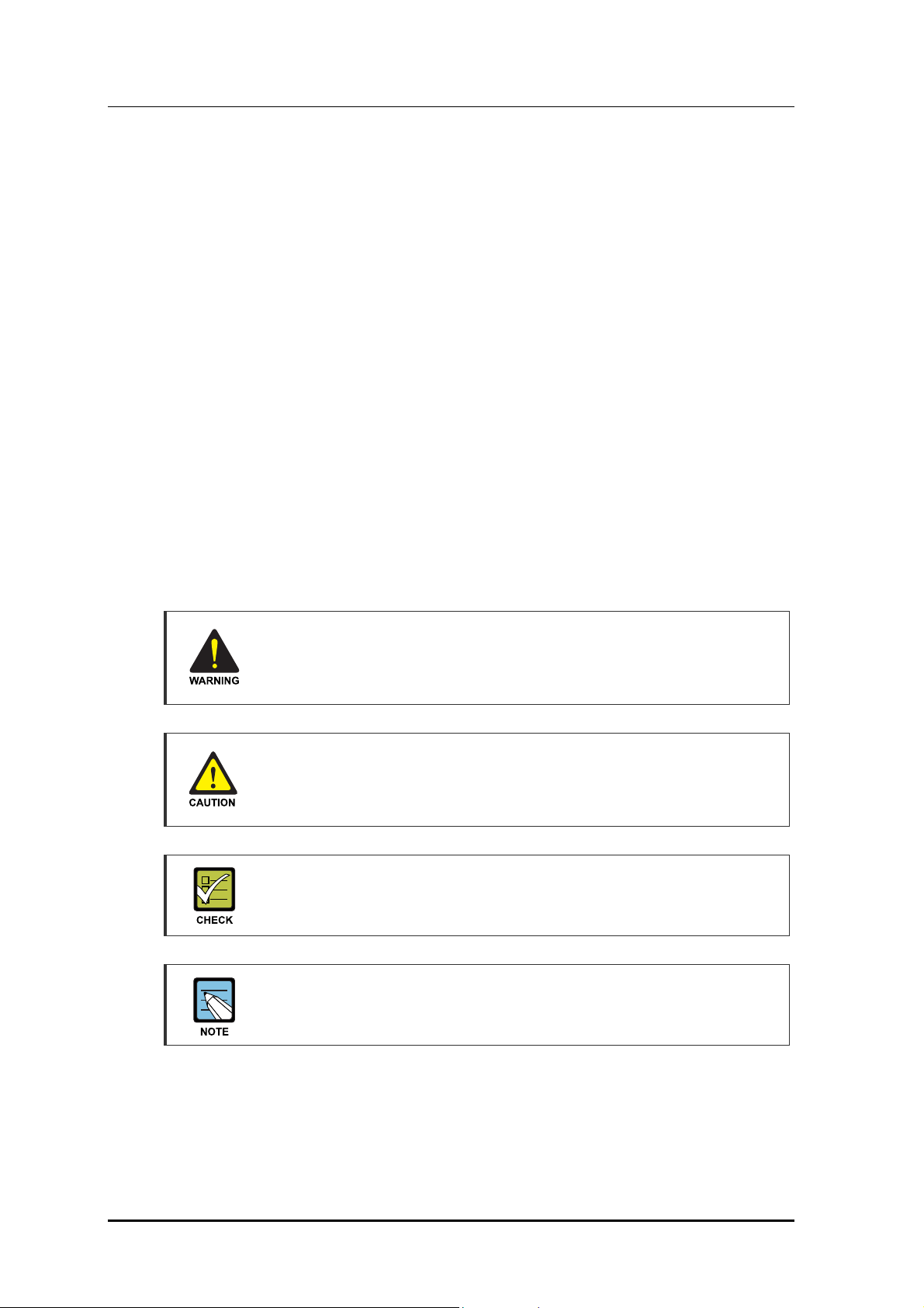
The following types of paragraphs contain special information that must be carefully read
and thoroughly understood. Such information may or may not be enclosed in a rectangular
box, separating it from the main text, but is always preceded by an icon and/or a bold title.
WARNING
Provides information or instructions that the reader should follow in order to avoid
personal injury or fatality.
CAUTION
Provides information or instructions that the reader should follow in order to avoid
a service failure or damage to the system.
CHECKPOINT
Provides the operator with checkpoints for stable system operation.
NOTE
Indicates additional information as a reference.
II
© SAMSUNG Electronics Co., Ltd.
Page 7
OfficeServ 7030 Installation Manual
Reference Documents
OfficeServ 7030 System Description
This manual introduces the OfficeServ 7030 and describes the system information
(hardware configuration, specification, functions etc.) necessary for this system.
OfficeServ 7030 Programming Manual
This manual describes how to use the MMC program to change the setting of the
OfficeServ 7030 system from the phone.
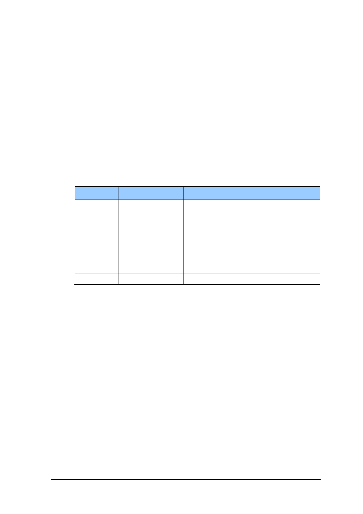
Revision History
EDITION DATE OF ISSUE REMARKS
00 06. 2008. First Draft
01 07. 2008. - Functions of BRI/MEM/LAN LED are changed.
- Cautions are added.
.Turning off power switch after dismounting MEM
.Checking MEM LED before power off
.Checking LAN Port LED
.Caution for using extension cable
02 01. 2009 Australian Release Version
03 02. 2009 Addition of Dual cabinet installation procedure
© SAMSUNG Electronics Co., Ltd. III
Page 8

Introduction Introduction
This page is intentionally left blank.
IV
© SAMSUNG Electronics Co., Ltd. IV
© SAMSUNG Electronics Co., Ltd.
Page 9
SAFETY CONCERNS
For product safety and correct operation, the following information must be given to the
operator/user and shall be read before the installation and operation.
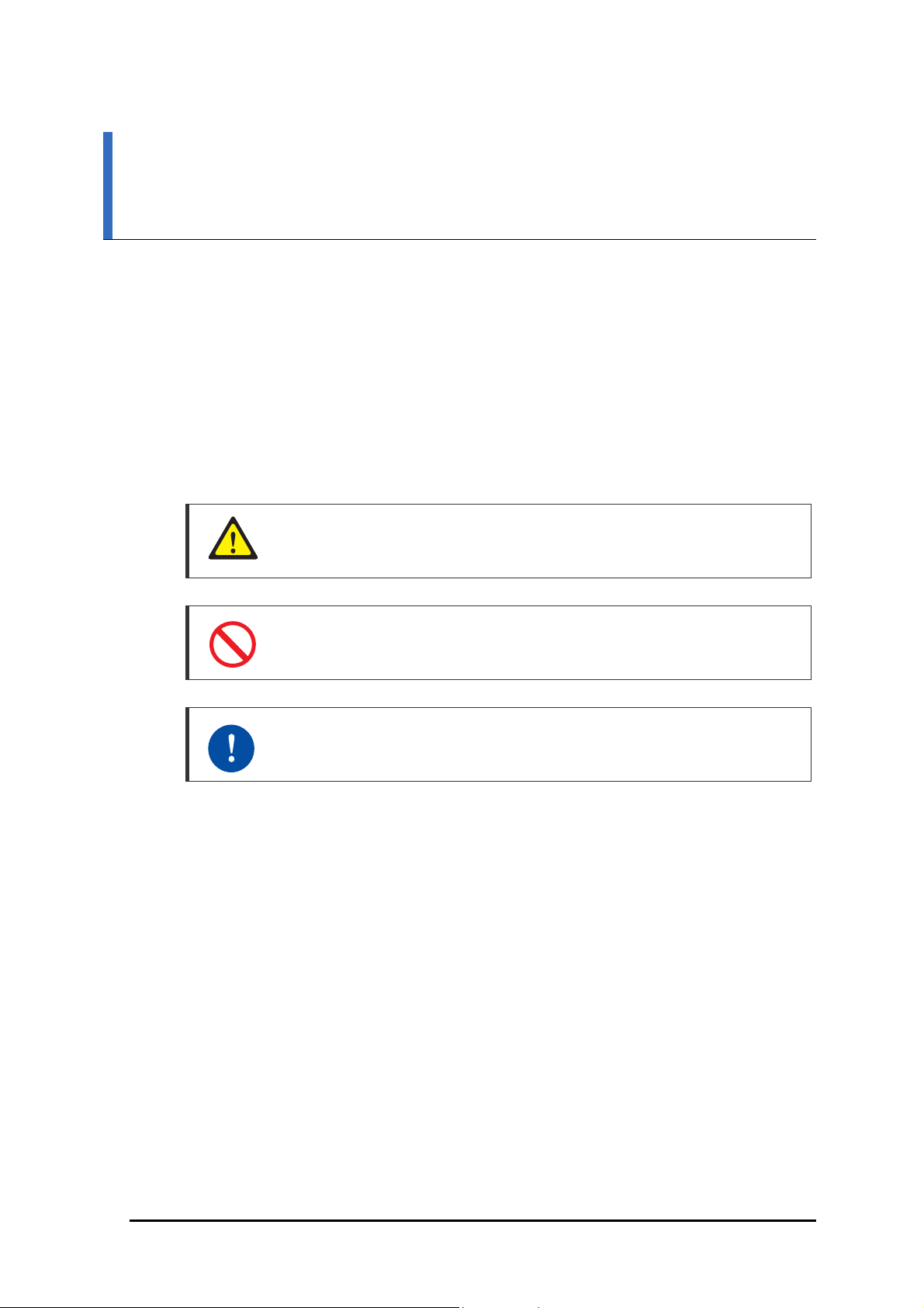
Symbols
Caution
Indication of a general caution
OfficeServ 7030 Installation Manual
Restriction
Indication for prohibiting an action for a product
Instruction
Indication for commanding a specifically required action
© SAMSUNG Electronics Co., Ltd. V
Page 10
Introduction
Warning
WARNING
Caution for grounding
The OfficeServ 7030 system is designed to be earthed through the Power cord,
and an external earth connection is not required for operation.
Using double-pole/neutral fusing
Do not attempt to repair the system after only removing the fuse from the neutral
line, doing so may cause electric shock. If the repair is required, unplug the
system's power cord before proceeding.
AC power connection restriction
Connect the system’s AC power to a separated AC outlet. If the AC power is used
together with other equipment, a system failure may occur due to static electricity
and/or voltage drop.
Caution for using expansion cabinet
Do not place the expansion cabinet directly on top of the basic cabinet. Doing so
may cause a system failure due to rising internal heat from the basic cabinet.
Caution for power supply when mounting the board
Check if the cabinet power is turned off when mounting the board. Inserting or
removing a board while the power is turned on may damage the board.
CAUTION
Caution for installation
Only trained service staff may install the OfficeServ 7030 system.
VI
© SAMSUNG Electronics Co., Ltd.
Page 11
OfficeServ 7030 Installation Manual
Telephone line cord
To reduce the risk of fire, use only No. 26 AWG or larger (e.g., 24 AWG), UL
Listed or CSA Certified Telecommunication Line Cord.
Prohibition of metal accessories
Do not wear metal accessories such as rings and watches while working on the
system to prevent electric damage to the system.
AC power connection restriction
Do not share the AC power of the OfficeServ 7030 system or the AC power of the
external UPS with other devices.
Checking MEM LED before power off
Don’t turn off the power while the MEM LED is flashing. This may cause data
corruption and malfunction of system. If you want to turn off power, dismount the
memory of the system with ‘Key MMC 817 MEM UMOUNT’.
Board reset
New settings are applied only after the board is reset. The system may
malfunction if the board is not properly initialized.
Checking LAN operation
Note that fitting an expansion EMP board can cause the LAN LED lights to flash,
even if a LAN cable is not present.
Caution for using two cabinet systems
When installing a two cabinet system, check that the extension cable is
connected during operation.
The expansion cabinet may malfunction if extension cable is not connected
during operation. In that case, you should connect extension cable again and
restart expansion cabinet.
© SAMSUNG Electronics Co., Ltd. VII
Page 12

Introduction
This page is intentionally left blank.
VIII
© SAMSUNG Electronics Co., Ltd.
Page 13

OfficeServ 7030 Installation Manual
TABLE OF CONTENTS
INTRODUCTION I
Purpose ......................................................................................................................................... I
Document Content and Organization ................................................................................................. I
Conventions ........................................................................................................................................... II
Reference Documents ....................................................................................................................... III
Revision History ................................................................................................................................. III
SAFETY CONCERNS V
Symbols ........................................................................................................................................ V
CHAPTER 1. Preparation 1-1
1.1 Site Information ..................................................................................................................... 1-1
1.1.1 Safety Conditions .................................................................................................................. 1-1
1.1.2 Tempera ture and Humidity Conditions ................................................................................. 1-1
1.2 Grounding Conditions ........................................................................................................... 1-2
1.3 Power Conditions .................................................................................................................. 1-2
1.4 Checking the Package ........................................................................................................... 1-3
1.5 Cabinet Configuration ........................................................................................................... 1-4
1.6 Card types available with the system .................................................................................. 1-7
1.7 System Installation Procedure .............................................................................................. 1-7
1.8 Dual Cabinet Installation Procedure .................................................................................... 1-8
CHAPTER 2. Mounting and Replacing the Boards 2-9
2.1 Working on the system .............................................................................................................. 2-9
2.1.1 Opening the cabinet .............................................................................................................. 2-9
2.2 Mounting the Boards ............................................................................................................2-11
2.2.1 Removing Blanking Panels ................................................................................................ 2-11
2.2.2 Setting Switches ................................................................................................................. 2-1 1
2.2.3 Mounting Optional Boards .................................................................................................. 2-13
© SAMSUNG Electronics Co., Ltd. IX
Page 14

Table of Contents
2.2.4 Mounting the daughter Boards ........................................................................................... 2-15
2.2.5 Closing/Cabling ................................................................................................................... 2-17
2.3 Replacing the Boards ........................................................................................................... 2-20
2.4 Dual Cabinet installation. ..................................................................................................... 2-22
CHAPTER 3. Installing the System 3-1
3.1 Installing on a Wall ................................................................................................................. 3-1
3.1.1 Required Tools ...................................................................................................................... 3-1
3.1.2 Installing on a Wall ................................................................................................................ 3-2
3.2 Connecting Basic and Expansion Cabinets ......................................................................... 3-3
CHAPTER 4. Connecting the Power 4-1
4.1 Connecting the Power ............................................................................................................ 4-1
4.1.1 Cautions when Connecting the Power ................................................................................. 4-1
4.1.2 Connecting the Power .......................................................................................................... 4-2
4.2 Connecting the External UPS ................................................................................................ 4-4
CHAPTER 5. Connecting the C.O. Line 5-1
5.1 Line Conditions ...................................................................................................................... 5-1
5.2 Connecting the C.O. Line ....................................................................................................... 5-2
5.2.1 Cautions When Connecting the C.O. Line ........................................................................... 5-2
5.2.2 Connecting Common C.O. Line ........................................................................................... 5-2
CHAPTER 6. Connecting the Stations and Additional Equipment 6-1
6.1 Connecting the Stations ........................................................................................................ 6-1
6.1.1 Cautions when Connecting the S ta tions .............................................................................. 6-1
6.1.2 Connecting Analog Phones .................................................................................................. 6-2
6.1.3 Connecting Digital Phones ................................................................................................... 6-3
6.1.4 Connecting IP Phones .......................................................................................................... 6-4
6.1.5 Connecting to a Door Phone and Door Lock ....................................................................... 6-5
6.1.6 Connecting a Wireless LAN Access Point ............................................................................ 6-6
6.2 Connecting Additional Equipment ........................................................................................ 6-7
6.2.1 Connecting the MOH/BGM Equipment ................................................................................ 6-7
6.2.2 Connecting External/Additional Page Equipment ................................................................ 6-8
6.2.3 Connecting Common Bells ................................................................................................... 6-8
6.2.4 Connecting Installation Tool .................................................................................................. 6-9
6.2.5 Configuring the network parameters using the MMC 830 ................................................. 6-10
X
© SAMSUNG Electronics Co., Ltd.
Page 15

OfficeServ 7030 Installation Manual
6.2.6 Configuring the Installation Tool parameters ...................................................................... 6-10
6.2.7 Connecting Web Management ........................................................................................... 6-11
6.2.8 Connecting the SMDR ........................................................................................................ 6-13
6.2.9 Connecting Printers ............................................................................................................ 6-14
CHAPTER 7. Starting the System 7-1
7.1 Pre-Check ............................................................................................................................... 7-1
7.1.1 Environment .......................................................................................................................... 7-1
7.1.2 Safety Conditions .................................................................................................................. 7-1
7.2 Starting the System ............................................................................................................... 7-2
7.3 Numbering Extensions and C.O. Lines ................................................................................ 7-2
7.4 Checking the System's Operation ........................................................................................ 7-3
7.4.1 S t ation Call Function ............................................................................................................. 7-3
7.4.2 S ta tion Camp-On Function ................................................................................................... 7-3
7.4.3 C.O. Line Call Function ......................................................................................................... 7-4
7.4.4 C.O. Line Camp-On Function ............................................................................................... 7-4
LIST OF FIGURES
Figure 1.1 Left Side View of the OfficeServ 7030 Cabinet ...................................................... 1-4
Figure 1.2 Top Side View of the OfficeServ 7030 Cabinet ...................................................... 1-5
Figure 1.3 Right Side View of the OfficeServ 7030 Cabinet ................................................... 1-6
Figure 2.1 Removing the cable duct cover (1) ........................................................................ 2-9
Figure 2.2 Removing the cable duct cover (2) ...................................................................... 2-10
Figure 2.3 Removing the screws .......................................................................................... 2-10
Figure 2.4 Removing the top cover ...................................................................................... 2-10
Figure 2.5 Removing the blanking panels ............................................................................. 2-11
Figure 2.6 Setting the Base Board Switches ........................................................................ 2-12
Figure 2.7 Mounting a MODEM Board on the Base Board ................................................... 2-13
Figure 2.8 Mounting an EPM Board on the Base Board ....................................................... 2-13
Figure 2.9 Setting Switches on the EPM Board.................................................................... 2-14
Figure 2.10 Location of the Base Board Slots ...................................................................... 2-15
Figure 2.11 Mounting 2BM/4T M on the Base Board ............................................................. 2-16
Figure 2.12 Mounting 4DM/4SM/4LM on the Base Board .................................................... 2-16
Figure 2.13 Tightening screws to install the daughter boards .............................................. 2-17
Figure 2.14 Installing the top cover (1) ................................................................................. 2-17
Figure 2.15 Installing the top cover (2) ................................................................................. 2-18
Figure 2.16 Cabling .............................................................................................................. 2-18
© SAMSUNG Electronics Co., Ltd. XI
Page 16

Table of Contents
Figure 2.17 Installing the duct cover (1) ................................................................................ 2-19
Figure 2.18 Installing the duct cover (2) ................................................................................ 2-19
Figure 2.19 Turning Off the Cabinet Power ........................................................................... 2-20
Figure 2.20 Removing the boards ......................................................................................... 2-21
Figure 2.21 Replacing the daughter boards .......................................................................... 2-21
Figure 3.1 Required Tools for the Installation on a Wall .......................................................... 3-1
Figure 3.2 Installation on a Wall (1) ......................................................................................... 3-2
Figure 3.3 Installation on a Wall (2) ......................................................................................... 3-2
Figure 3.4 Installation on a Wall (3) ......................................................................................... 3-2
Figure 3.5 Installation on a Wall (4) ......................................................................................... 3-3
Figure 3.6 Extension cable...................................................................................................... 3-3
Figure 3.7 Connecting the basic cabinet to the expansion cabinet ......................................... 3-4
Figure 4.1 Connecting the Power (use of a cabinet) ............................................................... 4-2
Figure 4.2 Connecting the Power (using Power cable) ........................................................... 4-3
Figure 4.3 Connecting an External UPS ................................................................................. 4-4
Figure 5.1 P1~P4 (RJ-45) Port of the 4TM Board ................................................................... 5-2
Figure 5.2 RJ-45 Port (T-Mode only) of the 2BM Board .......................................................... 5-2
Figure 6.1 SLT1 (RJ-45) Port of the Base Board .................................................................... 6-2
Figure 6.2 P1~P4(RJ-45) Port of the 4SM Board .................................................................... 6-2
Figure 6.3 P1~P4(RJ-45) Port of the 4DM Board ................................................................... 6-3
Figure 6.4 IP/Digital Phone Layout ......................................................................................... 6-4
Figure 6.5 RJ-45 Port of the Ethernet Connection Board ........................................................ 6-5
Figure 6.6 RJ-45 Port of the 4DM Boards (for Door Phone) ................................................... 6-5
Figure 6.7 Connecting MOH/BGM Sources ............................................................................ 6-7
Figure 6.8 Connecting External/Additional Page Equipment .................................................. 6-8
Figure 6.9 Connecting Common Bells .................................................................................... 6-8
Figure 6.10 Connecting Installation Tool ................................................................................. 6-9
Figure 6.11 Installation Tool .................................................................................................. 6-10
Figure 6.12 Web Management Initial Screen ........................................................................ 6-12
Figure 6.13 Connecting the SMDR ....................................................................................... 6-13
Figure 6.14 Connecting Printers ........................................................................................... 6-14
LIST OF TABLES
Table 1.1 Power Condition ...................................................................................................... 1-2
Table 1.2 Package Items ......................................................................................................... 1-3
Table 1.3 Parts on the left side of the cabinet ......................................................................... 1-4
Table 1.4 Parts on the top side of the cabinet ......................................................................... 1-5
Table 1.5 Parts on the right panel of the cabinet ..................................................................... 1-6
XII
© SAMSUNG Electronics Co., Ltd.
Page 17

OfficeServ 7030 Installation Manual
Table 1.6 Mountable Boards ................................................................................................... 1-7
Table 2.1 Jumpers/Switches of the Base/EPM Board ........................................................... 2-11
Table 2.2 Base Board Switches ............................................................................................ 2-12
Table 2.3 EPM board switches ............................................................................................. 2-14
Table 2.4 Mountable Boards ................................................................................................. 2-15
Table 2.5 Dual Cabinet Items ............................................................................................... 2-22
Table 2.6 Dual Cabinet Settings ........................................................................................... 2-22
Table 5.1 Line condition of the OfficeServ 7030 ..................................................................... 5-1
Table 6.1 Distance Between Stations and the System ........................................................... 6-1
Table 6.2 Specification for the Wireless LAN Connection ....................................................... 6-6
Table 6.3 Specifications for the PC for Programming ............................................................. 6-9
Table 6.4 Specification of the SMDR System ....................................................................... 6-13
© SAMSUNG Electronics Co., Ltd. XIII
Page 18

Table of Contents
This page is intentionally left blank.
XIV
© SAMSUNG Electronics Co., Ltd.
Page 19

CHAPTER 1. Preparation
This chapter describes the checklists (installation site, grounding & power conditions etc.)
which should be inspected before installing the OfficeServ 7030 system. This chapter also
describes the items included in the OfficeServ 7030 package and the installation procedure.
1.1 Site Information
Select a site that satisfies the following safety, temperature and humidity conditions.
OfficeServ 7030 Installation Manual
1.1.1 Safety Conditions
y OfficeServ 7030 system should not be installed near materials that can cause fire, such
as explosive gas and inflammable objects.
y OfficeServ 7030 system should not be installed near equipment that generates
electromagnetic waves, such as monitors or copying machines.
y The installation location should be easily accessible for trunk line and extension line
deployment, for power and grounding wire connection, and for maintenance and repair.
y OfficeServ 7030 system should not be installed in populated aisles/passageways or in
areas used for moving equipment.
y Keep the area clean. Prevent dust from damaging the cabinet's connectors.
y Before installing the OfficeServ 7030 system, check items such as the electric wiring
status, grounding status, voltage and frequency.
1.1.2 Temperature and Humidity Conditions
y The temperature and humidity conditions are as follows:
− Operation Temperature: 0~30°C
− Storage temperature: -10~50°C
− Humidity: 10~90%
y Cool area protected from direct sunlight.
y Ventilators should be installed to remove dust.
© SAMSUNG Electronics Co., Ltd. 1-1
Page 20
CHAPTER 2. Mounting boards
1.2 Grounding Conditions 1.2 Grounding Conditions
The Protective Earth (PE) connection to the OfficeServ 7030 cabinet is provided via the
The Protective Earth (PE) connection to the OfficeServ 7030 cabinet is provided via the
three core mains lead.
three core mains lead.
Ensure that the AC power point, which the OfficeServ 7030 system is connected to, is
Ensure that the AC power point, which the OfficeServ 7030 system is connected to, is
suitably grounded.
suitably grounded.
Hazardous telecommunications network volta ges may be present if analogue trunks Hazardous telecommunications network volta ges may be present if analogue trunks
are connected! Earth connection is essential before connecting analog ue
(PSTN) trunks. These trunks must be removed, then mains and battery power
disconnected, before the top panel is removed for ANY reason.
1.3 Power Conditions
The Power Supply Unit (PSU) of the OfficeServ 7030 system receives an AC input power
and supplies an output power of -54 V, +5 V, and +12 V to the system cabinet.
The power condition is as follows:
Table 1.1 Power Condition
Power Supply Standards
PSU Input Power
Output Power - DC -54 V, 0.5 A
AC 200~240 V
- DC +5 V, 3 A
- DC +12 V, 1.8 A
1-2
© SAMSUNG Electronics Co., Ltd.
Page 21
OfficeServ 7030 Installation Manual
1.4 Checking the Package 1.4 Checking the Package
The list of the items included in the OfficeServ 7030 package is as follows: The list of the items included in the OfficeServ 7030 package is as follows:
Table 1.2 Package Items Table 1.2 Package Items
Item Name Quantity Remark
Cabinet Basic Cabinet 1 Cable Power Cable 1 Template Wall Mount Template 1 Cover Cable guide / Connector cover 1 Bushing Wall mount Bushing 4 Screw Wall mount Screw 4 Lug Lug for connecting FGND 1
Manual Installation Manual - Supplied as PDF
UTP Cable Types
Two types of UTP cable are available: Straight-through UTP cable and Crossover
UTP cable. The Straight-through UTP cable is used to connect the OfficeServ
7030 system's 4LM module to another system.
© SAMSUNG Electronics Co., Ltd. 1-3
Page 22

CHAPTER 2. Mounting boards
1.5 Cabinet Configuration
Left Side View
Figure 1.1 Left Side View of the OfficeServ 7030 Cabinet
The descriptions of each part located on the left of the cabinet are listed in the table below.
Table 1.3 Parts on the left side of the cabinet
Part Function
Power Switch Turns the power of the OfficeServ 7030 system on/off.
Power I/O Connector Connector for the power cable connection
Turning off power switch after dismounting MEM
You should dismount MEM before turning off power switch. Use ‘Key MMC 817
MEM UMOUNT’ when dismounting MEM.
1-4
© SAMSUNG Electronics Co., Ltd.
Page 23

OfficeServ 7030 Installation Manual
Figure 1.2 Top Side View of the OfficeServ 7030 Cabinet
The descriptions of each part located on the top of the cabinet are listed in the table below.
Table 1.4 Parts on the top side of the cabinet
Part Function
RUN LED Main CPU operation status
- Off: Idle
- On (Green): Booting
- Blink (Green): Normal Operation of the Program
- ON (Red): Clearing the Flash Memory (Database)
LAN LED LAN operation status
- Off: LAN is not connected
- On (Green)
- LAN is connected
- EPM is connected
- Blink (Green): Tx/Rx of data through LAN port
MEM LED MEM operation status
- Off: Flash memory not loaded.
- On (Green): Flash memory loaded and normal operation.
- Blink (Green): Memory being accessed by application and
Read/Write/Erase operation in process.
BRI LED The port status
- Off: Not used
- On (Green) : In use
- Blink (Green) : BRI line is activated
© SAMSUNG Electronics Co., Ltd. 1-5
Page 24

CHAPTER 2. Mounting boards
Checking MEM LED before power off
Don’t turn off the power while the MEM LED is flashing. This may cause data
corruption and malfunction of system.
If you want to turn off power, dismount the memory of the system with
‘Key MMC 817 MEM UMOUNT’.
Checking LAN cable during lighting LAN LED on
Note that fitting an expansion EMP board can cause the LAN LED lights to flash,
even if a LAN cable is not present.
Figure 1.3 Right Side View of the OfficeServ 7030 Cabinet
The descriptions of each part located on the right of the cabinet are listed in the table below.
Table 1.5 Parts on the right panel of the cabinet
Part Function
C.O 1-4 Trunk ports
LINK1-3 Ports that connect the base cabinet with the expansion cabinet
EXT1-8 Station ports for subscribers (i.e analog phone, digital phone, LAN)
Reset Button for resetting the system
SLT1, 2 Station ports for analog phones
MISC Ports that connect external audio devices, paging device, loud bell,
common bell, or door bell
LAN LAN port
1-6
© SAMSUNG Electronics Co., Ltd.
Page 25

OfficeServ 7030 Installation Manual
1.6 Card types available with the system
The following cards can be fitted to the OS7030 system, depending on customer
requirements.
Table 1.6 Mountable Boards
Part Max qty per cabinet Description
4TM 1 4 port analogue trunk
2BM 1 2 port (4 channel) Basic Rate ISDN card
4DM 2 4 port Digital extension
4SM 2 4 port analogue extension
4LM 2 4 port LAN switch (requires EPM)
EPM 1 System expansion card
Modem 1 Analogue Modem card (OS7000 type)
Details of the installation of these cards are shown in the next Chapter.
1.7 System Installation Procedure
The system installation procedure is as follows:
1) Open the cabinet.
2) Remove the cabinet's blanking panels to insert the daughter boards.
3) Insert the daughter boards into the universal slots (slot 2, 3 and 4).
4) Install the cabinet on a wall, if necessary, depending on the installation environment
5) Connect and tie the cables with the cable ties.
6) Connect the AC 200~240 V input power. If necessary, connect Uninterruptible Power
Supply (UPS).
These items are described in detail in Chapter 2.
© SAMSUNG Electronics Co., Ltd. 1-7
Page 26

CHAPTER 2. Mounting boards
1.8 Dual Cabinet Installation Procedure
When installing a two cabinet system, the basic procedure is the same as for a one cabinet
system, described above. However, because both cabinets are identical when delivered, the
IP addresses of the second cabinet needs to be changed before they can be connected
together.
The Default IP addresses of each new cabinet are as follows:
Master IP address: 10.0.2.10
Gateway Address: 10.0.2.1
NetMask 255.255.255.0
Slave IP address: 10.0.2.12
When adding a second cabinet these need to be modified as described in Chapter 2.4
In addition the switch settings on the EPM module needs to be set.
1-8
© SAMSUNG Electronics Co., Ltd.
Page 27

OfficeServ 7030 Installation Manual
CHAPTER 2. Mounting and
Replacing the Boards
This chapter describes how to mount/replace various boards to/from the OfficeServ 7030
system.
2.1 Working on the system
This section describes how to open the cabinet and how to fit optional boards and check the
settings of switches on those boards.
Caution: Remove mains cable before starting work.
Always switch of the unit and remove the mains cable before opening the cabinet.
Hazardous voltages can exist inside the cabinet even when the unit is switched
off.
2.1.1 Opening the cabinet
1) Make sure the system is not connected to the mains supply.
2) Hold the cable duct cover and push upward as shown in the following picture.
Figure 2.1 Removing the cable duct cover (1)
© SAMSUNG Electronics Co., Ltd. 2-9
Page 28

CHAPTER 2. Mounting boards
3) Separate the cable duct cover.
4) Remove the two screws.
Figure 2.2 Removing the cable duct cover (2)
2-10
Figure 2.3 Removing the screws
5) Push and lift the top cover to open the case. Take care not to damage the light guide
fitted to the underside of the top cover.
Figure 2.4 Removing the top cover
© SAMSUNG Electronics Co., Ltd.
Page 29
OfficeServ 7030 Installation Manual
2.2 Mounting the Boards
This section describes how to set the base board switches and mount the optional boards.
2.2.1 Removing Blanking Panels
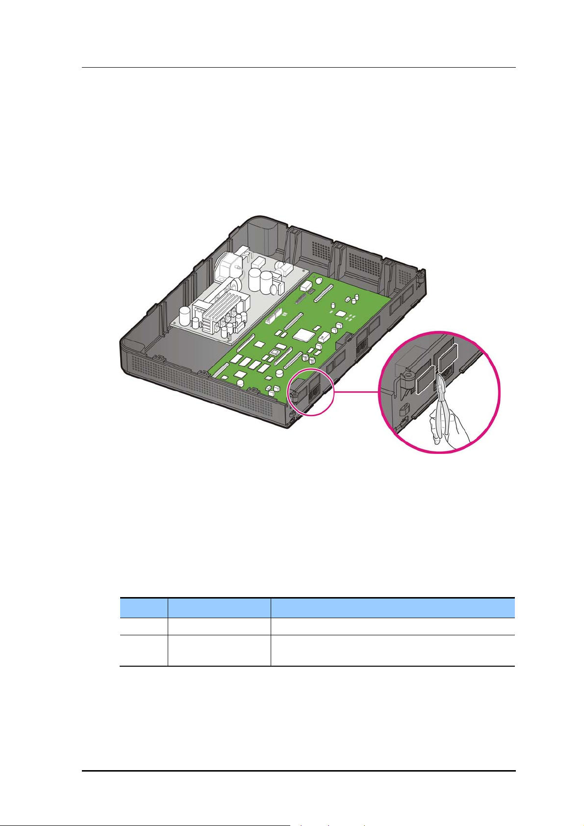
Depending on daughter boards, remove the cabinet's blanking panels with a cutter.
Figure 2.5 Removing the blanking panels
2.2.2 Setting Switches
The base board and the EPM board are both fitted with switches that might need to be set
by the installer depending on user requirements, as follows:
Table 2.1 Jumpers/Switches of the Base/EPM Board
Board Switch Description
Base S1 (1~8) Sets the country code
EPM S1 (1~2) Sets whether to use the 4LM daughter board and whether
to use the Expansion cabinet.
© SAMSUNG Electronics Co., Ltd. 2-11
Page 30

CHAPTER 2. Mounting boards
Setting switches on base board
Locate Switch 1 on the base board as shown below.
SW1 to SW4 are used to set the country code and will usually be preset to Australia.
SW6 is used to default the IP address if required, this is usually set to off
SW5, SW7 and SW8 are reserved for future use and are set to off
Figure 2.6 Setting the Base Board Switches
Table 2.2 Base Board Switches
Switch Description
S1 SW1
SW2
SW3
SW4
SW5 Reserved for future use
SW6 IP address Setting Mode
SW7~SW8 Reserved for future use
Off These switches set the system's country code.
Off
On
Off
When On : Forces Default factory address setting
When Off : Allows user to choose personal IP address setting
Note: The default for a new system is OFF.
S1
OFF
ON
2-12
© SAMSUNG Electronics Co., Ltd.
Page 31

OfficeServ 7030 Installation Manual
2.2.3 Mounting Optional Boards
When mounting the optional board, align the base board connectors to the optional board
(EPM or MODEM) connectors, and press the optional board firmly downward with both
hands
1) Mount the MODEM board to the base board's P7 and P8 connectors.
MODEM
Figure 2.7 Mounting a MODEM Board on the Base Board
2) Mount the EPM board to the base board's P2 connector.
EPM
Figure 2.8 Mounting an EPM Board on the Base Board
© SAMSUNG Electronics Co., Ltd. 2-13
Page 32

CHAPTER 2. Mounting boards
3) Secure the EPM Board with the supplied screw.
S1
ON
OFF
Figure 2.9 Setting Switches on the EPM Board
4) Locate S1 on the EPM board and Set SW1 and SW2 as required. (see below)
Table 2.3 EPM board switches
Switch Description
S1 SW1 - ON: Master cabinet
- Off: Slave cabinet.
SW2 - ON: Standalone
- Off: Master and slave
Note: Always check the EPM switch settings before installing the card, as an invalid setting may
prevent the system from starting.
2-14
© SAMSUNG Electronics Co., Ltd.
Page 33

OfficeServ 7030 Installation Manual
2.2.4 Mounting the daughter Boards
The following daughter boards can be mounted on the system card slots according to the
OfficeServ 7030 configuration.
Table 2.4 Mountable Boards
Part Slot Mountable Board
Trunk Part Slot 4 4TM, 2BM
Extension Part Slot 2 and Slot 3 4DM, 4SM, 4LM
slot 3
slot 2
slot 4
Figure 2.10 Location of the Base Board Slots
The 4TM Module board does not support Dial Pulse dialing, but it supports DTMF
dialing.
The 4LM (LAN card) requires that an EPM card is also installed to operate
correctly.
Caution for the power supply when mounting the boards
Check if the cabinet power is turned off when mounting the board. Inserting or
removing a board while the power is turned on may damage the board or cause
fire.
© SAMSUNG Electronics Co., Ltd. 2-15
Page 34
CHAPTER 2. Mounting boards
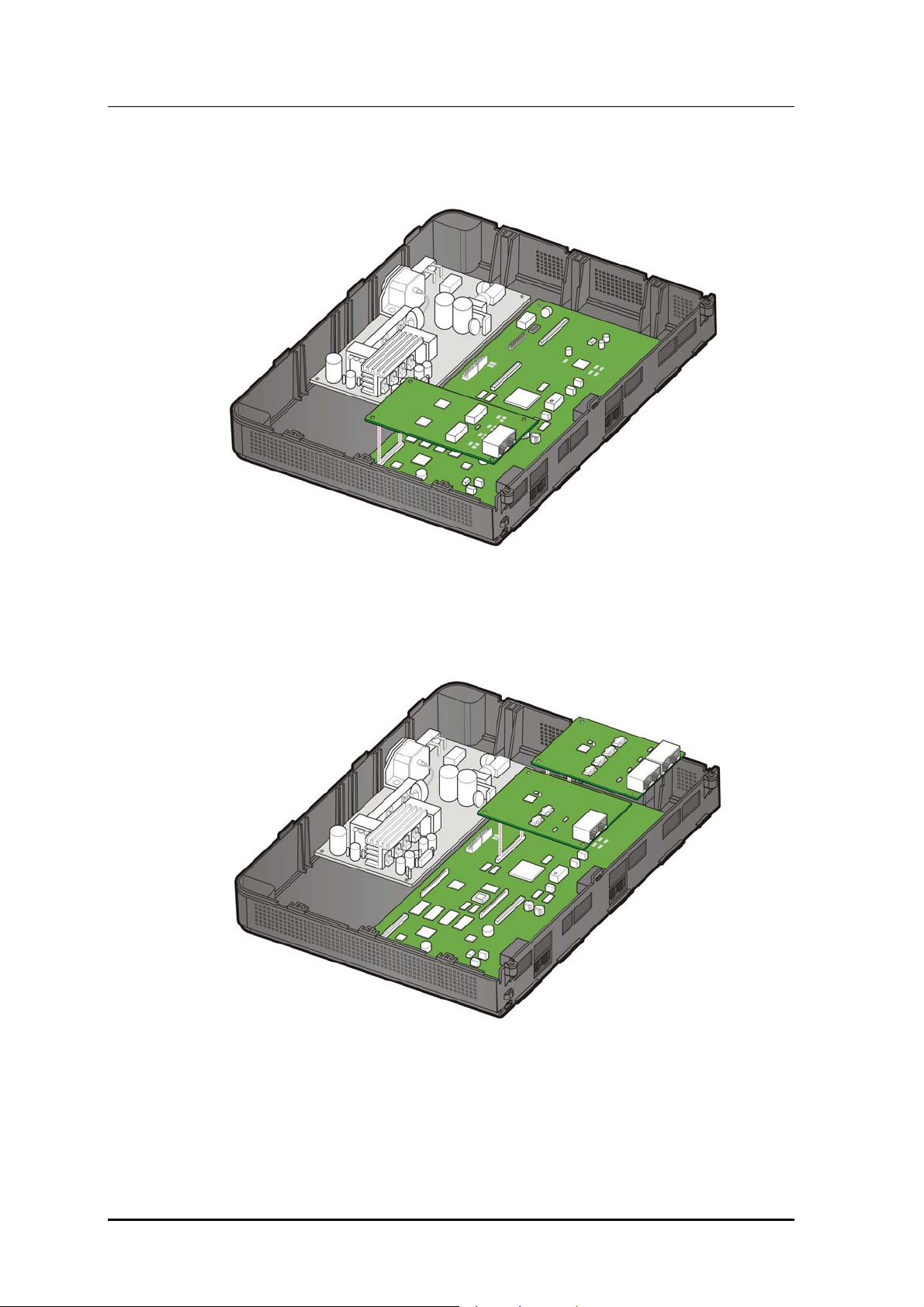
1) 2BM or 4TM can be mounted to the base board's P3 connector.
Figure 2.11 Mounting 2BM/4TM on the Base Board
2) 4DM, 4SM or 4LM can be mounted to the base board's P1 and P4 connector.
2-16
Figure 2.12 Mounting 4DM/4SM/4LM on the Base Board
© SAMSUNG Electronics Co., Ltd.
Page 35

OfficeServ 7030 Installation Manual
3) Secure the boards with the supplied screws.
Figure 2.13 Tightening screws to install the daught er boards
2.2.5 Closing/Cabling
1) Push and align the top cover to close the case.
Figure 2.14 Installing the top cover (1)
© SAMSUNG Electronics Co., Ltd. 2-17
Page 36

CHAPTER 2. Mounting boards
2) Tighten two screws to install the top cover.
Figure 2.15 Installing the top cover (2)
3) Fasten the cables to the cabinet with a cable tie.
2-18
Figure 2.16 Cabling
© SAMSUNG Electronics Co., Ltd.
Page 37

OfficeServ 7030 Installation Manual
4) Align and install the cable duct cover as follows.
Figure 2.17 Installing the duct cover (1)
5) Hold the cable duct cover and push downward as shown in the following picture.
Figure 2.18 Installing the duct cover (2)
© SAMSUNG Electronics Co., Ltd. 2-19
Page 38

CHAPTER 2. Mounting boards
2.3 Replacing the Boards
If the OfficeServ 7030 system fails to operate normally due to an error on the power supply
board, base board or daughter board, replace the board with a new one.
Removing the Cables
Before replacing a daughter board, remove all cables connected to the board.
To replace a board mounted in the slot of a cabinet, proceed as follows:
1) Turn off the power to the cabinet in which the board is mounted and remove the mains
cable.
2-20
Figure 2.19 Turning Off the Cabinet Power
2) Remove the cable duct cover and open the upper case. Refer to section ‘2.1.1
Opening’.
© SAMSUNG Electronics Co., Ltd.
Page 39

OfficeServ 7030 Installation Manual
3) Remove the screw and extract the board carefully.
Figure 2.20 Removing the boards
4) Align the new board to the connector of the slot, and press the daughter boards firmly
downward with two hands. Tighten the screw.
Figure 2.21 Replacing the daughter boards
5) Close the cabinet. Refer to section ‘2.2.5 Closing/Cabling’.
© SAMSUNG Electronics Co., Ltd. 2-21
Page 40

CHAPTER 2. Mounting boards
2.4 Dual Cabinet installation.
A Dual Cabinet installation consists of the following items.
Table 2.5 Dual Cabinet Items
Description Qty
OS7030 Cabinet 2
OS7030 Expansion Module (EPM) 2
OS7030 Expansion Cable 1
When installing a two cabinet system, the basic procedure is the same as for a one cabinet
system, described above. Each Cabinet in a two cabinet system requires an EPM card to be
fitted as described in section 2.2.3 above, and the switches need to be set as described
below.
Table 2.6 Dual Cabinet Settings
Cabinet EPM
Switch
Basic S1 SW1 - ON
Expansion S1 SW1 - OFF
Switch Settings
SW2 – OFF
SW2 - OFF
Default IP Address
Master IP: 10.0.2.10
Slave IP: 10.0.2.12
Master IP: 10.0.2.12
Slave IP: 10.0.2.10
However, because both cabinets are identical when delivered, the IP addresses of the
second cabinet needs to be changed before they can be connected together.
By default each system has a Master address and a Slave address, configurable through
MMC 830, the IT Tool, or the Web Browser. (See Chapter 6 for instructions on how to use
these tools).
Use these tools to connect to the slave cabinet and change the Master and Slave address as
shown above. (I.e. reverse the addresses, so Master becomes Slave and Slave becomes
Master), save the changes, then connect the expansion cable between the cabinets and
restart both systems.
If Custom IP addresses are to be used, the same process applies.
Note: If the cabinets have been used before, setting the Master and Slave IP addresses to
0.0.0.0 and resetting will force the system to revert to the factory defaults.
2-22
© SAMSUNG Electronics Co., Ltd.
Page 41

OfficeServ 7030 Installation Manual
CHAPTER 3. Installing the System
This chapter describes how to install an OfficeServ 7030 on the wall, if necessary,
depending on the installation environment.
3.1 Installing on a Wall
This section describes how to install the OfficeServ 7030 cabinet on a wall.
3.1.1 Required Tools
y Mid-sized Phillips screw driver
y Electric drill
y Hammer
y Wall Mount Template
y Four plastic Bushings
y Four cross-type screws
Figure 3.1 Required Tools for the Installation on a Wall
© SAMSUNG Electronics Co., Ltd. 3-1
Page 42

CHAPTER 3. Installing the system
3.1.2 Installing on a Wall
To install the OfficeServ 7030 cabinet with a wall mount template, proceed as follows:
1) Drill holes on the marked position of the Wall Mount Template. Drill holes with a
minimum of 33 mm depth and approx. 6 mm width to ease the insertion of the plastic
bushings.
Figure 3.2 Installation on a Wall (1)
2) Fix plastic anchors into the drilled holes with a hammer.
Figure 3.3 Installation on a Wall (2)
3) Align the screw holes of the wall-type bracket to the fixed plastic anchors' positions.
Insert the screws to each hole and tighten the screws with a Philips screw driver.
Figure 3.4 Installation on a Wall (3)
3-2
© SAMSUNG Electronics Co., Ltd.
Page 43

OfficeServ 7030 Installation Manual
4) Align the holes of the OfficeServ 7030 cabinet to the bracket screws, and then pull
down the cabinet to secure in place.
Figure 3.5 Installation on a Wall (4)
3.2 Connecting Basic and Expansion Cabinets
If the OfficeServ 7030 system is a dual cabinet installation, connect the Basic cabinet to the
expansion cabinet using the extension cables to allow signal transmissions between the
base boards.
1) Three extension cables are needed to connect the Basic cabinet to the expansion
cabinet. These are provided as a labeled cable set.
Figure 3.6 Extension cable
2) With an extension cable, connect the basic cabinet's ‘Link1’ port to the extension
cabinet's ‘Link1’ port.
© SAMSUNG Electronics Co., Ltd. 3-3
Page 44

CHAPTER 3. Installing the system
3) With another extension cable, connect the ‘Link2’ port to the ‘Link2’ port.
4) With the third cable, connect the ‘Link3’ to the ‘Link3’.
Figure 3.7 Connecting the basic cabinet to the expansion cabinet
Caution for using expansion cabinet
Do not place the expansion cabinet directly on top of the basic cabinet. Doing so
may cause a system failure due to rising internal heat from the basic cabinet.
Caution for using extension cable
Check if extension cable is connected during operation. The expansion cabinet
may malfunction if extension cable is not connected during operation. In that
case, you should connect extension cable again and restart expansion cabinet.
Ensure that the EPM switches and IP address are correct as shown in section 2.4.
Incorrect setting may prevent the system from starting.
3-4
© SAMSUNG Electronics Co., Ltd.
Page 45

OfficeServ 7030 Installation Manual
CHAPTER 4. Connecting the Power
This chapter describes how to connect the power to the OfficeServ 7030 system and how to
connect the external UPS.
4.1 Connecting the Power
4.1.1 Cautions when Connecting the Power
When the input power is normally supplied, AC current is supplied to the Power Supply
Unit (PSU). If the input power is interrupted, the system can be operated using the external
UPS.
When connecting the power to the OfficeServ 7030 system, pay attention to the following
criteria:
y The system supports 200~240 V AC power.
y A single AC outlet should be used solely for the system’s AC power. Sharing the AC
power with other devices can cause static and/or voltage drop, resulting in system
malfunction.
y Use a stable power source that can supply continuous AC power; instantaneous power
failures may cause malfunctions.
© SAMSUNG Electronics Co., Ltd. 4-1
Page 46

CHAPTER 4. Connecting Power
4.1.2 Connecting the Power
Single cabinet configuration
Use the power cable provided with the OfficeServ 7030 system to connect the input power
terminal located on the right panel of the basic cabinet to a grounded outlet.
Figure 4.1 Connecting the Power (use of a cabinet)
4-2
© SAMSUNG Electronics Co., Ltd.
Page 47
OfficeServ 7030 Installation Manual
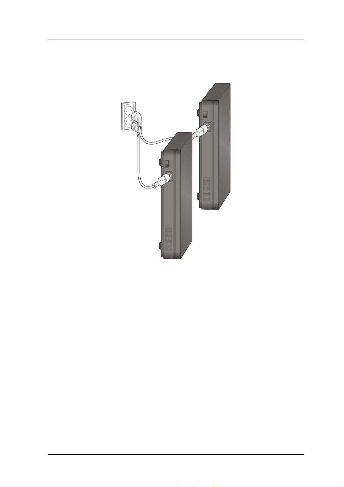
Basic and Expansion Cabinet Configuration
Connect each input power cable of the cabinet to a grounded outlet.
Figure 4.2 Connecting the Power (using Power cable)
© SAMSUNG Electronics Co., Ltd. 4-3
Page 48

CHAPTER 4. Connecting Power
4.2 Connecting the External UPS
An optional external Uninterruptible Power Supply (UPS) is required to ensure stable
operation of the OfficeServ 7030 system in case of a power failure. The rated capacity of
an external UPS is AC 200~240 V per cabinet. The UPS should be connected to each
cabinet to guarantee safety.
To connect an external UPS to the OfficeServ 7030 system, proceed as follows:
1) Prepare the UPS as specified in the documentation supplied with the product.
2) Connect each cabinet.
UPS
4-4
Figure 4.3 Connecting an External UPS
© SAMSUNG Electronics Co., Ltd.
Page 49

OfficeServ 7030 Installation Manual
CHAPTER 5. Connecting the C.O.
Line
This chapter describes how to connect the C.O. line to the OfficeServ 7030 system after
installation.
5.1 Line Conditions
When connecting the C.O. lines, pay attention to the following criteria:
y Use an AWG #24 or AWG #26 cables.
y When wiring the cables in humid areas, remove the moisture before wiring.
y The cables should be handled carefully to prevent any distortions or damages.
y The subscriber lines should be kept indoors if at all possible.
y Do not cable the subscriber lines around any high-voltage power line.
The leak resistance of the C.O. line connected to the OfficeServ 7030 system is as follows:.
Table 5.1 Line condition of the OfficeServ 7030
Line Condition Leak Resistance
Leak Resistance between Lines 20 kΩ or higher
Leak Resistance Between Grounds 20 kΩ or higher
© SAMSUNG Electronics Co., Ltd. 5-1
Page 50

CHAPTER 6. Connecting Lines
5.2 Connecting the C.O. Line
This section describes how to connect a common C.O. line (4TM and 2BM)
5.2.1 Cautions When Connecting the C.O. Line
When connecting the C.O. line, pay attention to the following criteria to prevent bodily
injuries and system damages:
y Do not connect the C.O. line in extreme weather conditions such as storm and
lightning.
y Do not connect the C.O. line in humid areas.
5.2.2 Connecting Common C.O. Line
Use a pair of AWG #24 (or AWG #26) cable to connect a common C.O. line to the
terminal pin of a terminal box connected to the OfficeServ 7030 system equipped with a
4TM or 2BM board.
Connecting to the 4TM Board
P1 ~P4-Port
(RJ-45)
Pin No. 1 2 3 4 5 6 7 8
Function - - - C.O TIP C.O RING - - -
Figure 5.1 P1~P4 (RJ-45) Port of the 4TM Board
Connecting to the 2BM Board
P1, P2 Port
(RJ-45)
5-2
Pin No. 1 2 3 4 5 6 7 8
Function - - TX + RX + RX - TX - - -
Figure 5.2 RJ-45 Port (T-Mode only) of the 2BM Board
© SAMSUNG Electronics Co., Ltd.
Page 51

OfficeServ 7030 Installation Manual
CHAPTER 6. Connecting the Stations
and Additional Equipment
This chapter describes how to connect various stations and additional equipment
(analog/digital phones, door phones, door locks etc.) to the OfficeServ 7030 system.
6.1 Connecting the Stations
6.1.1 Cautions when Connecting the Stations
When connecting the stations, pay attention to the following criteria:
y Do not connect the stations in extreme weather conditions such as storm and lightning.
y Do not connect the stations in humid areas.
y Comply with the manual of the station as well as with this document when
reconnecting the stations or changing the connections.
y Connect the stations with a pair of #24 AWG or #26 AWG cables.
The maximum distances between the stations and the OfficeServ 7030 system are as
follows:
Table 6.1 Distance Between Stations and the System
Installation Distance Standards
Digital Phone Maximum 400 m (AWG #24)
Analog Phone Maximum 1 km (AWG #24)
Door Phone Maximum 400 m (AWG #24)
SMT-R2000 Maximum 100 m (Ethernet cable)
© SAMSUNG Electronics Co., Ltd. 6-1
Page 52

CHAPTER 6. Connecting extensions and devices
6.1.2 Connecting Analog Phones
Connect an analog phone to the base board's SLT, or to the 4SM board mounted on the
OfficeServ 7030 system.
Connecting to the Base Board’s SLT
Connect an analog phone to the ports of the base board's SLT with a pair of AWG #24 or
AWG #26 cables.
Pin No. 1 2 3 4 5 6 7 8
SLT1 and SLT2
(RJ-45)
Function - SLI
TIP
Figure 6.1 SLT1 (RJ-45) Port of the Base Board
SLI
RING
- - -
Connecting to the 4SM Board
Connect an analog phone to the port of the 4SM board with a pair of AWG #24 or AWG
#26 cables.
P1~ P4 Port
(RJ-45)
Pin No. 1 2 3 4 5 6 7 8
Function - - - SLI
TIP
SLI
RING
-
6-2
Figure 6.2 P1~P4(RJ-45) Port of the 4SM Board
© SAMSUNG Electronics Co., Ltd.
Page 53

OfficeServ 7030 Installation Manual
6.1.3 Connecting Digital Phones
Connect a digital phone to the base board's 4DM.
Connecting to the 4DM Board
Connect a digital phone to the ports of the base board's 4DM with a pair of AWG #24 or
AWG #26 cables.
P1~ P4 Port
(RJ-45)
Pin No. 1 2 3 4 5 6 7 8
Function - DLI
Figure 6.3 P1~P4(RJ-45) Port of the 4DM Board
TIP
DLI
RING
- - -
© SAMSUNG Electronics Co., Ltd. 6-3
Page 54

CHAPTER 6. Connecting extensions and devices
6.1.4 Connecting IP Phones
An IP phone is a phone that provides calls through the Ethernet LAN. The base board can
support up to four MGI channels which enables the use of the IP phones. These ports are
enabled by adding a Licence key to the system.
The interface between a digital phone connected to the OfficeServ 7030 system and an IP
phone connected to the LAN is as follows.
1) The connection between a digital phone and an IP phone is established/released using
the IP address of the LAN connected to the OfficeServ 7030 system.
2) The digital phone connected to the OfficeServ 7030 system converts the analog voice
data to PCM voice data and transmits the data to the base board through the 4DM
board.
3) The PCM voice data is converted to packet data by the base board and transferred to
the IP phone.
the IP phone.
4) The IP phone converts the packet voice data to analog voice signals and displays the
4) The IP phone converts the packet voice data to analog voice signals and displays the
signals through a handset or speaker.
signals through a handset or speaker.
5) The Voice signals coming from the IP phone are converted to packet data and
5) The Voice signals coming from the IP phone are converted to packet data and
transmitted to the base board in the same way. The base board converts the packet
transmitted to the base board in the same way. The base board converts the packet
voice data to PCM voice data and transmits the data to the digital phone through the
voice data to PCM voice data and transmits the data to the digital phone through the
4DM board. The digital phone converts and sends the PCM voice data to analog data.
4DM board. The digital phone converts and sends the PCM voice data to analog data.
Configure the MMC setting to suit the system before use. Configure the MMC setting to suit the system before use.
the base board and transferred to
OfficeServ 7030
IP phone
Figure 6.4 IP/Digital Phone Layout Figure 6.4 IP/Digital Phone Layout
Digital phone
6-4
© SAMSUNG Electronics Co., Ltd.
Page 55
OfficeServ 7030 Installation Manual
6.1.4.1 Connecting Boards to the Ethernet LAN
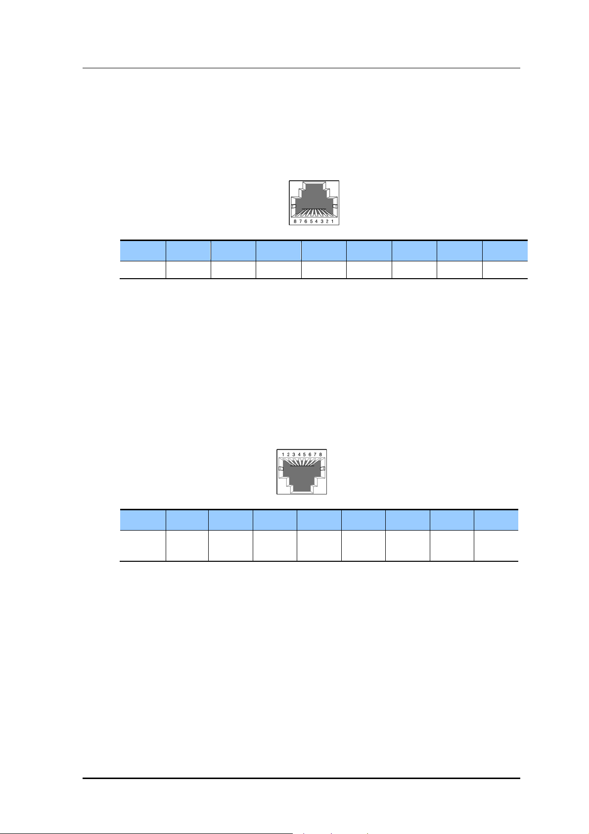
4LM/LAN port of the base board can be connected to the Ethernet with an Ethernet cable.
y 4LM Board-Line Ports (P1~P4)
y Base Board-LAN Port
P1~P4 Port
/LAN Port
(RJ-45)
Pin No. 1 2 3 4 5 6 7 8
Function Tx+ Tx- Rx+ - - Rx- - -
Figure 6.5 RJ-45 Port of the Ethernet Connection Board
6.1.5 Connecting to a Door Phone and Door Lock
Connect a door phone and a door lock to the OfficeServ 7030 system with a Door Phone
Interface Module (DPIM). Connect a pair of #24 AWG or #26 AWG cables to the LINE
port of the DPIM and the ports of the OfficeServ 7030 system's 4DM board.
Connecting to the 4DM Boards
P1~ P4 Port
(RJ-45)
Pin No. 1 2 3 4 5 6 7 8
Function - - - DLI TIP DLI
RING
Figure 6.6 RJ-45 Port of the 4DM Boards (for Door Phone)
- - -
1) Connect the Door port of the DPIM and the line port of the DOOR BOX.
2) When using an automatic door lock, connect the Lock port of the DPIM and the door
phone contact point to the door lock.
The door lock contact point is designed to control the low-voltage relay and is operated
with a 12 VDC, 100 mA current.
© SAMSUNG Electronics Co., Ltd. 6-5
Page 56

CHAPTER 6. Connecting extensions and devices
MMC
MMC 211 is used to assign call numbers to the door phones.
6.1.6 Connecting a Wireless LAN Access Point
The wireless LAN service offered by the OfficeServ 7030 system requires the following
equipment:
y SMT-R2000: Wireless LAN Access Point (AP)
y SMT-W5100: Wireless LAN IP phone
Table 6.2 Specification for the Wireless LAN Connection
Item OfficeServ 7030 System (Ba sic Cabinet)
Maximum number of users 16
Number of simultaneous users MMC845 setting
For information on how to install and use the SMT-R2000 and SMT-W5100, refer
to the ‘VoWLAN Administration Guide’.
Connect the 4LM board and the SMT-R2000 WAN port with a RJ-45 Ethernet cable
(maximum distance:100m).
Note: The SMT-R2000 cannot get power from the 4LM and needs to be connected to an
external power source.
6-6
© SAMSUNG Electronics Co., Ltd.
Page 57

OfficeServ 7030 Installation Manual
6.2 Connecting Additional Equipment
This section describes how to connect optional equipment (Music on Hold
(MOH)/Background Music (BGM) sources, external page devices, common bells etc.) to
the OfficeServ 7030 system.
6.2.1 Connecting the MOH/BGM Equipment
The OfficeServ 7030 system offers music while on hold.
The system provides internal tone/music and external music sources from the C.O. or
extension line music sources. The selection of internal/external music sources is performed
through MMC 861. One external music source is provided while on hold; the external
music source is connected to the MISC port.
A pair of MOH/BGM source lines is connected to Pin4 and Pin5 of the base board’s MISC
port.
The user's MOH/BGM source
Figure 6.7 Connecting MOH/BGM Sources
MMC
Select music s ources for the C.O. lines through MMC 408; select music sources
for extensions through MMC 308. To use the external music source, select this
option through MMC 861 (default is internal).
© SAMSUNG Electronics Co., Ltd. 6-7
Page 58
CHAPTER 6. Connecting extensions and devices
6.2.2 Connecting External/Additional Page Equipment
Instead of an internal speaker, external broadcasting equipment (amps or speakers) and
additional equipment that can broadcast page/ring signals outside the building can be
connected to the OfficeServ 7030 system. Connect the external/additional page equipment
to the MISC port of the base board mounted on the OfficeServ 7030 system. The power
cord of the external/additional page equipment should be connected separately.
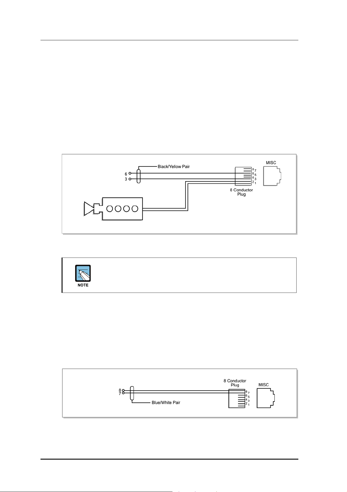
The OfficeServ 7030 system supports several channels for external broadcasting and one
dry contact. If a pair of External Page Equipment lines is connected to Pin3 and Pin6, the
Dry Contact 1 line is connected to Pin1 and Pin2, and the Dry Contact 2 line is connected
to Pin7 and Pin8 of the base board’s MISC port.
Dry Contact
(for Common bell)
External Page Equipment
Figure 6.8 Connecting External/Additional Page Equipment
Dry Contact
A Dry Contact is a switch that can establish or release a power/line connection of
an external equipment.
6.2.3 Connecting Common Bells
A Common Bell is a type of ring service. When a ring is received by an extension of a
group, all extensions of the given group also receive the ring.
To use the common bell, connect the common bell to the MISC port mounted on the
OfficeServ system. The OfficeServ 7030 system supports only one dry contact for the
common bell.
Dry contact
(for common
6-8
Figure 6.9 Connecting Common Bells
© SAMSUNG Electronics Co., Ltd.
Page 59

OfficeServ 7030 Installation Manual
6.2.4 Connecting Installation Tool
The system maintenance software is installed on a PC for programming. The Installation
Tool is an application that provides various functions necessary for system maintenance.
You can use the Installation Tool when you need to install a new system component or
change a system component or modify the database.
Below are the specifications required for the PC for programming where the Installation
Tool is to be installed.
Table 6.3 Specifications for the PC for Programming
Item Specification
PC CPU Pentium 4 or faster
Main Memory 512 MBytes or more
HDD Drive At least 30 MBytes of free space
OS Microsoft Windows XP or newer
Modem 1,200~115,200 baud rate
6.2.4.1 Connecting a PC for Programming Using a LAN Port
You can connect a PC where the Installation Tool is installed to the OfficeServ 7030 system
using a LAN port. The Installation Tool allows you to manage the OfficeServ 7030 system
remotely. This section describes how to connect a PC for programming to the OfficeServ
7400 system and how to configure the software to use that PC.
If a LAN is configured in your company, connect it to the LAN port of the Base board and
the PC for programming to it. If no LAN is configured in your company, connect the PC
for programming to the LAN port of the 4LM/Base board.
OfficeServ 7030
Installation Tool
Figure 6.10 Connecting Installation Tool
© SAMSUNG Electronics Co., Ltd. 6-9
Page 60

CHAPTER 6. Connecting extensions and devices
Below are the steps for connecting a PC for programming to the system.
1) Configure the network parameters using MMC 830.
2) Configure the Installation tool parameters.
6.2.5 Configuring the network parameters using the MMC 830
This step configures the network parameters of the OfficeServ 7030 system. Consult your
network administrator for the network parameter values. (See also section 2.4)
1) Set the IP addresses of the OfficeServ 7030 system. (Master and Slave)
2) Set the subnet mask of the OfficeServ 7030 system.
3) Set the gateway IP address of the OfficeServ 7030 system.
4) Reset the board.
Resetting the Board
You have to reset the board to apply the new settings. If the board is not reset
correctly, it may cause product malfunction.
6.2.6 Configuring the Installation Tool parameters
1) Run the Installation Tool.
2) On the main screen of the Installation Tool, select [System] Æ [Link Contro l] or
click the Port Basic icon.
6-10
Figure 6.11 Installation Tool
© SAMSUNG Electronics Co., Ltd.
Page 61

OfficeServ 7030 Installation Manual
3) When the <Link Control> is displayed, enter the name of the system in the [Name]
field.
4) If the Link Type is LAN, enter the IP address of the OfficeServ 7030 system in the
[IP Addr ess] field.
If the Link Type is MODEM, enter the internal modem number of the OfficeServ 7030
system in the [Telephone] field.
6.2.7 Connecting Web Management
The OfficeServ 7030 system is equipped with the Web Management web server, and
supports remote access through the network. The system administrator can change the
system setting by accessing the Web Management screens with an internet browser.
This section describes how to access the OfficeServ 7030 system.
To use within an in-house network, connect LAN to the LAN port of the base board and try
accessing from a client PC.
Setting the Network parameter through MMC830
Set the network parameter of the OfficeServ 7030 system. The required setting for this
address will be determined by the network administrator. (see also section 2.4)
1) Set the IP addresses of the OfficeServ 7030 system. (Master and Slave)
2) Set the subnet mask of the OfficeServ 7030 system.
3) Set the gateway address of the OfficeServ 7030 system.
4) Reset the board.
Resetting the Board
To apply the new setting, the board must be reset.
Default IP Address
The default IP addresses for a new System are as follows
Basic Cabinet: 10.0.2.10
Expansion Cabinet: 10.0.2.12
© SAMSUNG Electronics Co., Ltd. 6-11
Page 62
CHAPTER 6. Connecting extensions and devices
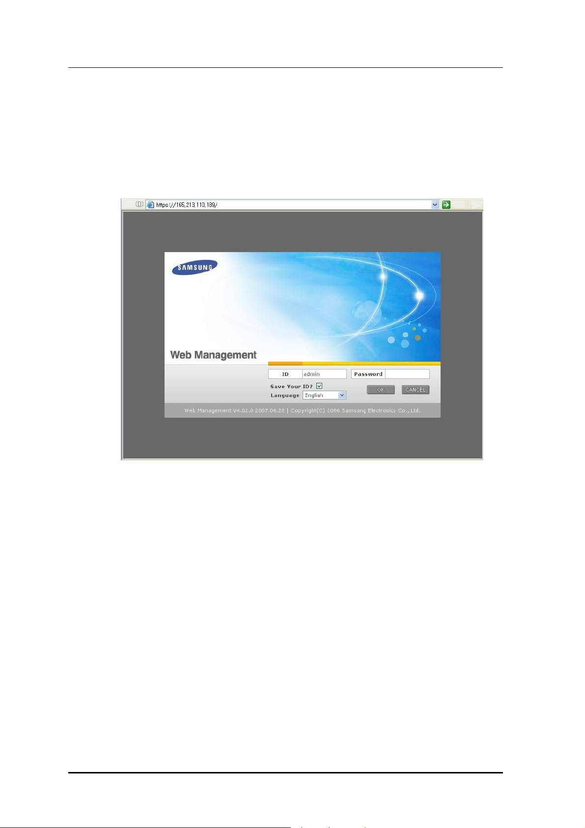
Getting access to the Web Management from a client PC
1) Execute your browser. (Internet Explorer 5.5 or higher)
2) Access the Web Management through the LAN IP address.
Access address: https://[System LAN IP Address]
Figure 6.12 Web Management Initial Screen
3) Enter your ID and password on the Web Management initial screen, and click the [OK]
button to log in.
Note:
The default ID is admin
The default password is samsung
6-12
© SAMSUNG Electronics Co., Ltd.
Page 63
OfficeServ 7030 Installation Manual
6.2.8 Connecting the SMDR
The Station Message Detail Recording (SMDR) computer is used for recording call
information, calculating phone bills and/or displaying various analysis data based on the
call data provided by the system.
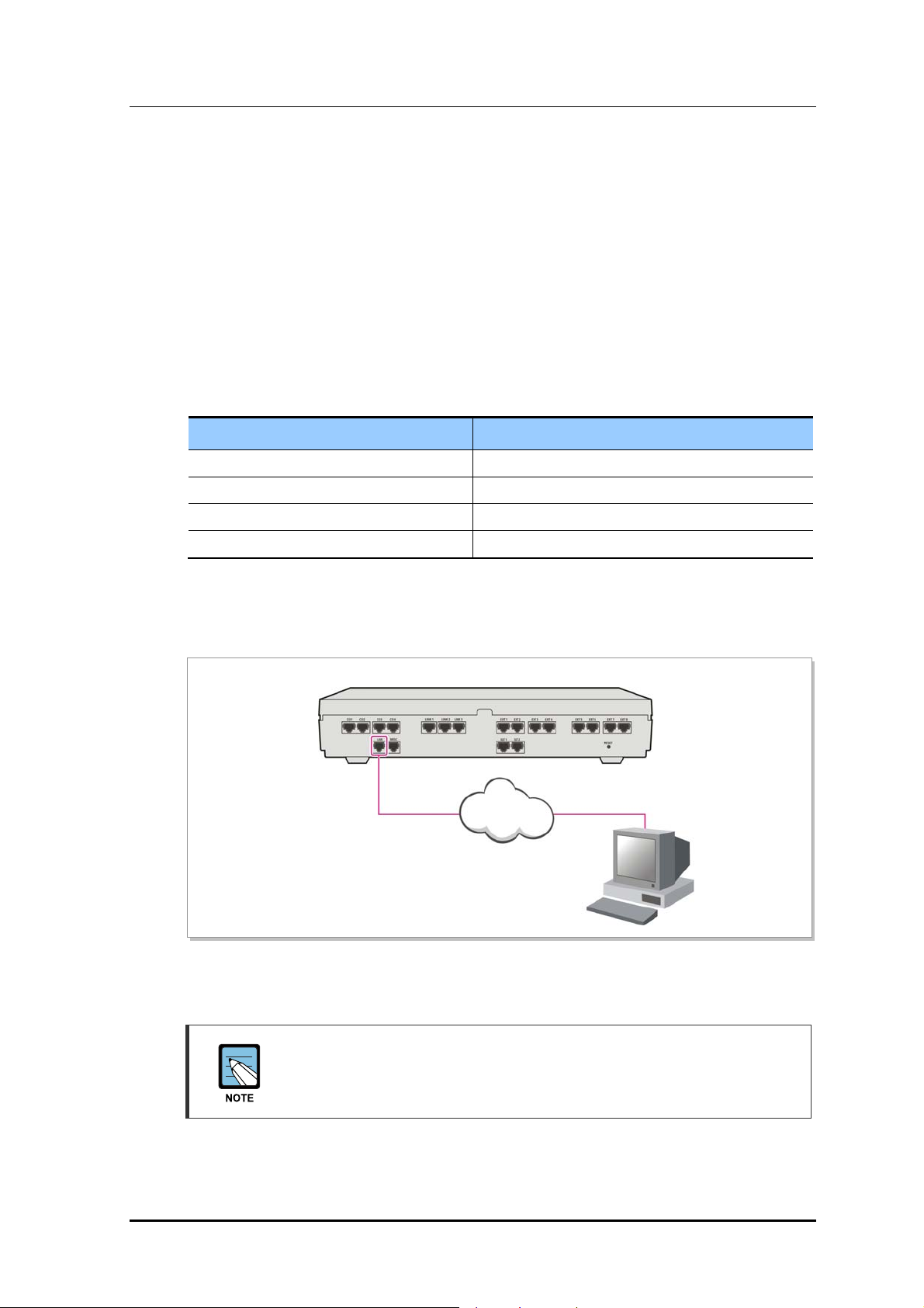
The SMDR computer can be connected via the LAN port of the 4LM board or the base
board built in the OfficeServ 7030 system.
The SMDR system specification is as follows:
Table 6.4 Specification of the SMDR System
Item Specification
Platform IBM PC
CPU Pentium 4 or higher
Operating System Windows XP or later
Main Memory 512 MByte or more
To use within the company's LAN network, connect LAN to the LAN port of the Base
board, and connect a SMDR computer to the LAN.
OfficeServ 7030
LAN
SMDR
Figure 6.13 Connecting the SMDR
MMC
Refer to the programming manual for details of how to configure the system for
SMDR and/or Printer operation.
© SAMSUNG Electronics Co., Ltd. 6-13
Page 64
CHAPTER 6. Connecting extensions and devices
6.2.9 Connecting Printers
The OfficeServ 7030 system can be connected to printers. The system can print various call
information or event information created by the system in real time whenever an event
occurs.
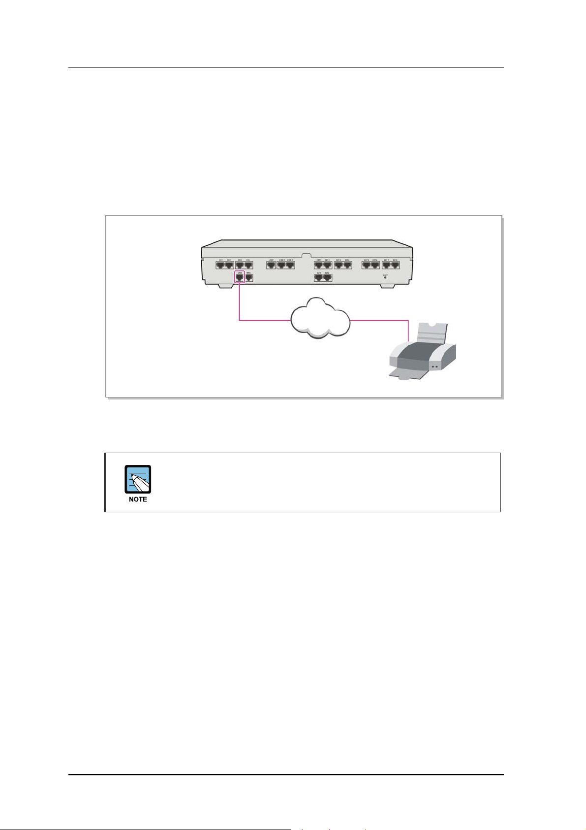
To use within the company's LAN network, connect LAN to the LAN port of the Base
board, or the 4LM if fitted, and connect a printer to the LAN. a printer to the LAN.
OfficeServ 7030
LAN
Figure 6.14 Connecting Printers Figure 6.14 Connecting Printers
MMC MMC
Refer to the programming manual for details of how to configure the system for
SMDR and/or Printer operation.
Printer
6-14
© SAMSUNG Electronics Co., Ltd.
Page 65

OfficeServ 7030 Installation Manual
CHAPTER 7. Starting the System
This chapter describes the items to check before starting the OfficeServ 7030 system, as
well as the procedure for starting the system and the procedure for testing whether the
system is operating normally after startup.
7.1 Pre-Check
This section describes the items to check before starting the OfficeServ 7030 system.
7.1.1 Environment
y Temperature
Check if the room temperature is between 0°C and 30
above or below the operational temperature, install a heating/cooling device to
maintain the operational temperature.
y Humidity
Check if the humidity of the room is between 10% and 90%. Take special caution
since the humidity affects the electric components and the connectors of the system.
y Direct Sunlight and Dust
The room where the OfficeServ 7030 system is installed should be protected from
direct sunlight and should have ventilation systems to prevent the system from
malfunctioning due to dusts.
7.1.2 Safety Conditions
The building where the OfficeServ 7030 system is installed should have lightning rods and
groundings to protect the system from lightning and electric leakage.
y Check if the OfficeServ 7030 system is not inclined and is in level position.
o
C. If the room temperature is
y Do not place devices that may cause electromagnetic interference near the system.
y Place a fire extinguisher near the system. Since spring coolers can seriously damage
the system, use extinguishers such as Halor 1301 and Carbon Dioxide.
y Ensure that the input power of the OfficeServ 7030 system is AC 200~240 V. Do not
share the power with other electric devices, such as motors and compressors.
© SAMSUNG Electronics Co., Ltd. 7-1
Page 66

CHAPTER 7. Starting the System
7.2 Starting the System
To start the OfficeServ 7030 system, proceed as follows:
1) Check if the boards and cables are properly mounted and connected to the OfficeServ
7030 cabinet.
2) Turn on the power of the OfficeServ 7030 basic cabinet, and turn on the power of the
expansion cabinet.
3) Check the LEDs from the base boards mounted on the OfficeServ 7030 cabinet.
y The RUN LED of the base board turns green and the MEM LED flashes when the
system starts the booting process normally.
y Once the booting is completed, the RUN LED of the base board flashes green, and
the MEM LED stops flashing
4) The MEM LED of the base board flashes green when the Flash Memory is accessed.
7.3 Numbering Extensions and C.O. Lines
Once the OfficeServ 7030 system is booted, the base board verifies the boards mounted in
each slot and saves this information as the default configuration of the system.
The C.O. line numbers from 701 are sequentially assigned to the C.O. line board mounted
on Slot 4 of the basic cabinet, and the subsequent numbers are respectively assigned to the
expansion cabinet. This numbering process continues until the C.O. line numbers are
assigned to all C.O. lines
The extension numbers from 201 are sequentially assigned to the extension board mounted
on Slot 1 of the basic cabinet, and the subsequent numbers are respectively assigned to the
next extension board of the next slot. This numbering process continues until the extension
numbers are assigned to all extensions. However, only the numbers from 201 to 349 are
assigned when using 3 digits.
By default, the first port of the first 4DM board is assigned to the attendant group. All C.O.
lines will ring this attendant extension unless the default value is changed. Thus, a phone
with an LCD panel should be connected to the first port of the first 4DM board.
The numbers between 500~549 are assigned to extension groups.
The numbers of C.O. lines, extensions, or extension groups can be changed using the MMC
724 program.
7-2
© SAMSUNG Electronics Co., Ltd.
Page 67

OfficeServ 7030 Installation Manual
7.4 Checking the System's Operation
After starting the OfficeServ 7030 system, check if the system is operating normally.
Check if the basic functions of the OfficeServ 7030 system (Station Call, Station Camp-On,
C.O. Line Call, C.O. Line Camp-On etc.) are properly executed.
7.4.1 Station Call Function
Follow the procedure below and check if the calls between the stations are enabled:
1) Lift the handset of a station.
Verify the intercom dial tone.
2) Press an extension number.
Check if the dial tone stops.
3) Press all extension numbers.
Verify the ring back tone.
4) Once the recipient answers the call, check the call status.
5) Hang up the phone and call a busy station.
Verify the busy tone.
7.4.2 Station Camp-On Function
If a caller dials a number and the recipient is busy, this function automatically connects the
recipient and the caller right after the recipient hangs up the call.
Follow the procedure below and check the Station Camp-On function:
1) Lift the handset of the test phone and dial a busy station.
Verify the busy tone.
2) Upon checking the dial tone, press the hook flash button.
Check if the busy tone stops.
3) Press the reservation code.
Verify the confirmation tone.
4) Lift the handset of the test phone and dial a busy station.
Check if the test phone rings.
5) Lift the handset of the test phone.
Check if the ring stops. Confirm the ring-back tone.
Check if the other phone rings.
6) Lift the handset of the other phone.
Check if the other phone stops ringing, if the ring-back tone of the test phone stops,
and if the parties are normally connected.
© SAMSUNG Electronics Co., Ltd. 7-3
Page 68

CHAPTER 7. Starting the System
7.4.3 C.O. Line Call Function
Follow the procedure below and check if the external calls are connected normally.
1) Lift the handset of the test phone.
Verify the intercom dial tone.
2) Press the C.O. line call code.
Verify the C.O. line dial tone.
3) Check if an error tone is activated on the phones that do not support C.O. line calls.
4) Press an external number.
Verify the ring back tone.
5) Once the call is connected, check the call status.
7.4.4 C.O. Line Camp-On Function
If a caller presses a C.O. line code to make an external call and all C.O. lines are busy, this
function reserves a C.O. line and notifies the caller if the C.O. line becomes available.
Follow the procedure below and check the C.O. Line Camp-On function.
1) Lift the handset of the test phone and press a C.O. line code.
Verify the C.O. line dial tone.
2) Check if a busy tone rings when all C.O. lines are busy.
3) Upon verifying the busy tone, press the hook flash switch of the test phone.
Check if the busy tone stops.
4) Press the code number of the C.O. line Camp-On function.
Verify the confirmation tone.
5) Hang up the test phone and make the C.O. line idle.
Check if the test phone rings and if the C.O. line becomes busy.
6) Lift the handset of the test phone.
Check if the test phone stops ringing. Verify the intercom dial tone and the C.O. line
dial tone.
7-4
© SAMSUNG Electronics Co., Ltd.
Page 69

ABBREVIATION
2
2BM 2 port BRI Module
4
4DM 4 port DLI Module
4LM 4 port LAN Module
4SM 4 port SLI Module
4TM 4 port Trunk Module
OfficeServ 7030 Installation Manual
A
B
D
G
AC Alternating Current
AFT Automatic Function Test
AP Access Point
AWG American Wire Gauge
BGM Background Music
DC Direct Current
DLI Digital Line Interface
DPIM Door Phone Interface Module
DSL Digital Subscriber Line
GND Ground
I
IP Internet Protocol
© SAMSUNG Electronics Co., Ltd. I
Page 70

Abbreviation
L
M
P
S
LAN Local Area Network
LCD Liquid Crystal Display
LED Light Emitting Diode
MOH Music on Hold
MGI
PCM Pulse Code Modulation
PSU Power Supply Unit
SLI Single Line Interface
SMDR Station Message Detail Recording
T
U
TEPRI2 T1E1PRI
TRK Trunk
UTP Unshielded Twisted Pair
UPS Uninterruptible Power Supply
UTP Unshielded Twisted Pair
II
© SAMSUNG Electronics Co., Ltd.
Page 71

OfficeServ 7030
Installation Manual
©2008 Samsung Electronics Co., Ltd.
All rights reserved.
Information in this manual is proprietary to SAMSUNG
Electronics Co., Ltd.
No information contained here may be copied, translated,
transcribed or duplicated by any form without the prior written
consent of SAMSUNG.
Information in this manual is subject to change without notice.
 Loading...