

Samsung NP-R560 Disassembly

- 이 문서는 삼성전자의 기술 자산으로 승인자만이 사용할 수 있습니다 -
- This Document can not be used without Samsung's authorization -
3. Disassembly and Reassembly
3-1. Disassembly and Reassembly R560
[Caution] Attention to red sentence.
Part Picture Description
1. Make sure to separate the AC adapter and battery before
disassembling the system.
2. Slide the knob all the way to the end in the direction of
2
1 1
the arrows (1) and push the battery in the direction of the
arrows (2).
Main
System
3. If you push the battery upwards, the battery is separated.
4. emove the screws from the bottom.
- Screw
Red ( ): M2.6 X L8, Black (16EA)
Yellow ( ): M2 X L4, Black (7EA)
Sky blue ( ):M2 X L6, Black (2EA)
5. Remove DOOR-HDD and DOOR-MEMORY.
3-1

3-2
3. Disassembly and Reassembly
- 이 문서는 삼성전자의 기술 자산으로 승인자만이 사용할 수 있습니다 -
- This Document can not be used without Samsung's authorization -
Part Picture Description
6. HDD is under the DOOR-HDD.
Seizing INSULATOR, lift up HDD by 70°.
[Caution]
Do not give too strong force when lifting up HDD.
Disassemble HDD before upside-downing System.
7. Separate the ODD like picture.
Main
System
8. Remove KBD and BOTTOM fastening Screw.
Remove ODD and BOTTOM fastening Screw.
M2 X L3, Black (1EA)
M2 X L6, Silver (2EA)
9. By tweezers push Hook to outer side then lift up
Keyboard
[Caution]
Be careful not to make a Scratch on Housing-Top.

- 이 문서는 삼성전자의 기술 자산으로 승인자만이 사용할 수 있습니다 -
- This Document can not be used without Samsung's authorization -
3. Disassembly and Reassembly
Part Picture Description
10. Lifting up Keyboard and unfasten Touchpad-FFC.
11. Put tweezers on each recess of Cap-Top and hold up
Cap-Top.
Main
System
[Caution]
Don’t leave mark or Scratch.
12. Remove Cap-Top.
13. Unfasten Antenna Cable on W/L card then remove a
screw and Module. [Aux(Black)]
1. White, Main
3. Gray, MIMO (* Option)
2. Black, Aux
3-3
3-4
3. Disassembly and Reassembly
- 이 문서는 삼성전자의 기술 자산으로 승인자만이 사용할 수 있습니다 -
- This Document can not be used without Samsung's authorization -
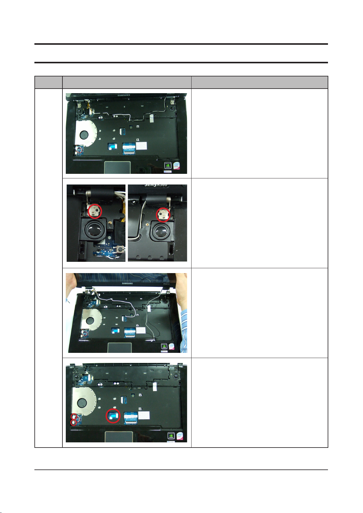
Part Picture Description
14. Disassemble CAMERA-CABLE, LCD CABLEW/L and
ANTENNA-CABLE from Housing-Top.
15. Remove two screws fastening HINGE and TOP.
M2 X L6 (2EA)
Main
System
16. Elevate LCD Assy and disassemble from system part.
17. Remove FFC-touchpad, SPEAKER CONN.and MIC
CONN. from main board.
 Loading...