

Page 1

Chapter 1.
Getting Started
Product Features 2
Before You Start 3
Contents 6
Safety Precautions 7
Proper Posture During Computer Use 21
Important Safety Information 24
Replacement Parts and Accessories 26
Regulatory Compliance Statements 28
WEEE SYMBOL INFORMATION 40
Overview 41
Front View 41
Status Indicators 42
Right View 43
Left View 44
Back View 45
Bottom View 46
Turning the Computer On and Off 47
Turning the computer on 47
Turning the computer off 48
Page 2
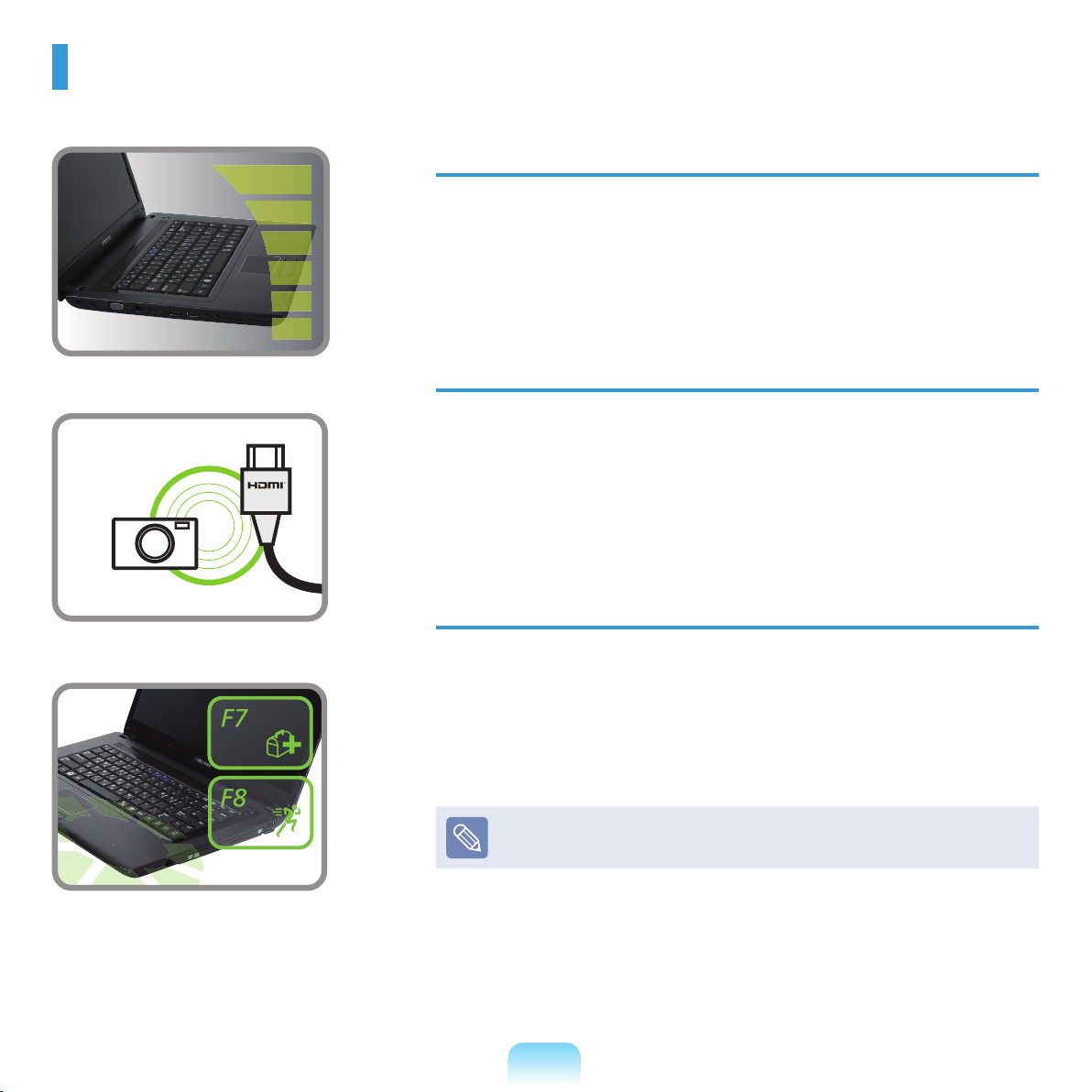
Product Features
High-Performance Notebook Computer
Intel Core™2 Duo, Intel® Celeron, Intel® Pentium Dual Core processor
and DDR II Memory (Optional)
Wireless LAN (Optional), Bluetooth (Optional)
Supports Various Multimedia Functions
A video chatting/conference function adopting the camera module
(Optional)
An HDMI port that enables viewing a full HD picture on the TV
(
Optional)
Easy-to-Use and Convenient Functions
Various Hot Key Functions
Multi-Card Slot
Luxurious, Ergonomic Design
Optional items may be changed or may not be provided depending on the
computer model.
2
Page 3
Before You Start
Before reading the User Guide, rst check the following information.
Optional items, some devices and software referred to in the User Guide may not be provided and/or changed by upgrade.
Note that the computer environment referred in the User Guide may not be the same as your own environment.
Images used in this User Guide may differ from actual product.
This guide decribes procedures for using both the mouse and the touchpad.
This manual has been written for the Windows operating system. The descriptions and gures may differ depending on the
installed operating system.
The User guide supplied with this computer may vary depending on your model.
Safety Precaution Notations
Icon Notation Description
Warning
Caution
Failing to follow instructions marked with this symbol, may cause personal injury and or
fatality.
Failing to follow instructions marked with this symbol, may cause slight injury to yourself or
damage your property.
Text Notations
Icon Notation Description
Before You Start Content included in this section includes information required before using a function.
Caution Content included in this section includes information required about the function.
Note Content included in this section includes helpful information to use the function.
3
Page 4

Copyright
© 2009 Samsung Electronics Co., Ltd.
Samsung Electronics Co., Ltd. owns the copyright of this manual.
No part of this manual may be reproduced or transmitted in any form or by any means, electronic or mechanical, without
the consent of Samsung Electronics Co., Ltd.
The information in this document is subject to change without notice due to improving the performance of the product.
Samsung Electronics shall not be liable for any data loss. Please take care to avoid losing any important data and backup
your data to prevent any such data loss.
Precautions for Operating System Support
If a problem occurs because of the reinstallation of other operating systems(OS) or a previous version of a OS preinstalled on this computer, or a software that does not support the OS, the company will not provide technical support, a
replacement or refund, and if our service engineer visits you due to this problem, a service charge will be applied.
About the Product Capacity Representation Standard
About HDD Capacity Representation
The capacity of the storage device (HDD, SSD) of the manufacturer is calculated assuming that 1KB=1,000 Bytes.
However, the operating system (Windows) calculates the storage device capacity assuming that 1KB=1,024 Bytes, and
therefore the capacity representation of the HDD in Windows is smaller than the actual capacity due to the difference in
capacity calculation.
(E.g. For a 80GB HDD, Windows represents the capacity as 74.5GB, 80x1,000x1,000x1,000 byte/
(1,024x1,024x1,024)byte = 74.505GB)
In addition, the capacity representation in Windows may be even smaller because some programs such as Recovery
Solution may reside in a hidden area of the HDD.
About Memory Capacity Representation
The memory capacity reported in Windows is less than the actual capacity of memory.
This is because BIOS or a video adapter uses a portion of memory or claims it for further use.
(E.g. For 1GB(=1,024MB) memory installed, Windows may report the capacity as 1,022MB or less)
4
Page 5

Recovery Solution Representation (Optional)
Q. What is a Recovery Area?
A. – Samsung computers have an additional partition to recover computers or save backup les. (Only for models with
the Samsung Recovery Solution.)
This partition is called a Recovery Area and it includes a recovery image that comprises of the OS and application
programs.
- You can either double-click the Samsung Recovery Solution icon on the desktop or press F4 while booting the
computer to enter the Recovery Area. Then you can back up the present computer state or recover the computer
from backed up images.
- For deleting the Recovery Area, you need to use an additional Recovery Area Removal Tool. After deleting the
recovery area, you can use the newly created partition for other uses, such as for saving personal data. Be careful
that once the recovery area is deleted, the Samsung Recovery Solutions will not work anymore.
Q. The capacity representation of the hard disk drive(HDD) in Windows is different from the product
specications.
A. - The capacity of the storage device (HDD) of the manufacturer is calculated assuming that 1KB=1,000 Bytes.
However, the operating system (Windows) calculates the storage device capacity assuming that 1KB=1,024
Bytes, and therefore the capacity representation of the HDD in Windows is smaller than the actual capacity. This
is due to the difference in capacity calculation and does not mean the installed HDD is different from the product
specications.
- The capacity representation in Windows may be smaller than the actual capacity because some programs occupy a
certain area of the HDD outside of Windows.
- For models with Samsung Recovery Solution, the HDD capacity representation in Windows may be smaller than
the actual capacity because Samsung Recovery Solution uses a hidden area of about 5~20GB of the HDD to save
the recovery image, and that hidden area is not counted towards the total size available to Windows. The size of
Samsung Recovery Solution varies by models because of the different size of applied programs.
5
Page 6

Contents
Chapter 1. Getting Started
Product Features 2
Before You Start 3
Contents 6
Safety Precautions 7
Proper Posture During Computer Use 21
Important Safety Information 24
Replacement Parts and Accessories 26
Regulatory Compliance Statements 28
WEEE SYMBOL INFORMATION 40
Overview 41
Front View 41
Status Indicators 42
Right View 43
Left View 44
Back View 45
Bottom View 46
Turning the Computer On and Off 47
Turning the computer on 47
Turning the computer off 48
Chapter 2. Using the Computer
Keyboard 50
Touchpad 52
Basic Touchpad Functions 52
The Gesture Function of the Touchpad (Optional) 54
Touchpad On/Off Function 56
CD Drive (ODD, Optional) 57
Inserting and Ejecting a CD 57
Multi Card Slot
ExpressCard Slot (Optional) 62
Connecting a monitor / TV 63
Connecting to the Monitor / TV 63
Viewing Through a Monitor / TV 65
Using Dual View 69
Adjusting the Volume 71
Wired Network 73
Wireless Network 76
Connecting to a Wireless LAN 76
(Optional) 59
Chapter 3. Settings and Upgrade
LCD Brightness Control 80
BIOS Setup 81
Entering the BIOS Setup 81
The BIOS Setup Screen 82
Setting a Boot Password 84
Changing the Boot Priority 86
Upgrading Memory 87
Battery 89
Installing/Removing the Battery 89
Charging the Battery 90
Measuring the Remaining Battery Charge 91
Extending the Battery Usage Time 92
Using the Security Lock Port 93
Chapter 4. Troubleshooting
Using Samsung Recovery Solution (Optional) 95
Samsung Recovery Solution Functions 95
Restore Function 98
Backup Function 101
System Software Function 105
Reinstalling Windows 7/Vista
(For Windows 7 and Windows Vista.
For supported models only) 107
Q & A 111
Windows Related 111
Display Related 113
Sound Related 114
Wired Network (LAN) Related 115
Wireless Network (WLAN) Related 117
Game and Program Related 121
Bluetooth 122
Blu-Ray (Optional) 123
Chapter 5. Appendix
Product Specications 125
Glossary 127
Index 130
6
Page 7
Safety Precautions
For your security and to prevent damage, please read the following safety instructions carefully.
Since this is commonly applied to Samsung Computers, some pictures may differ from actual products.
Warning
Failing to follow instructions marked with this symbol may cause personal injury and even fatality.
Installation Related
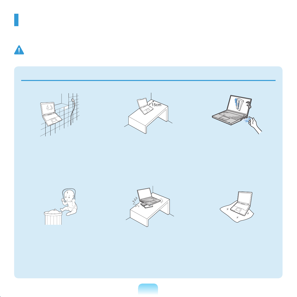
Do not install the product in places
exposed to humidity such as a
bathrooms.
There is a danger of electric
shock. Use the product within the
operating conditions specied in the
Manufacturers User Guide.
Keep the plastic bags out of the
reach of children.
There is a danger of suffocation.
Keep a distance of 15cm or more
between the computer and the
wall and do not place any objects
between them.
This may increase the internal
temperature of the computer and may
cause an injury.
Do not install the computer on a
slant or a place prone to vibrations,
or avoid using the computer in that
location for a long time.
This increases the risk that a
malfunction or damage to the product
will occur.
7
Avoid exposing any part of your
body to the heat from the computer
vent or AC adapter for a long time
when the computer is on.
Exposing a part of your body close to
the heat from the vent or AC adapter
for long periods of time may cause a
burn.
Avoid blocking the vent at the
bottom or side of the computer
when using it on a bed or cushion.
If the vent is blocked, there is a
danger of damaging the computer or
overheating the inside of the computer.
NP Ver 2.2
Page 8
Warning
Failing to follow instructions marked with this symbol may cause personal injury and even fatality.
Power Related
The power plug and wall outlet gures may differ depending on the country specications and the
product model.
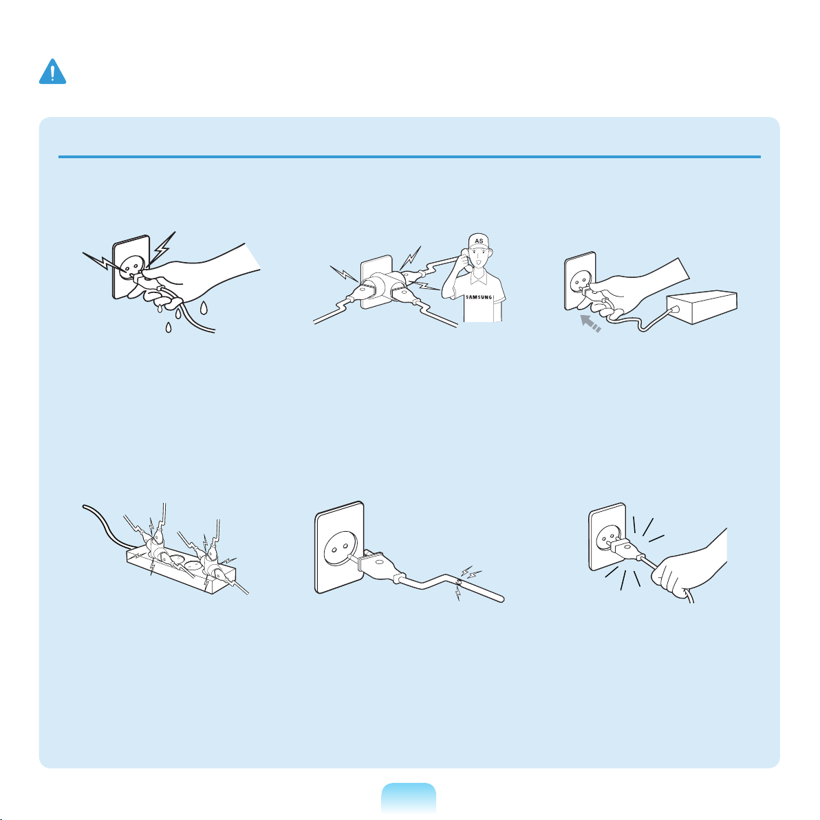
Do not touch the main plug or
power cord with wet hands.
There is a danger of electric shock.
Do not exceed the standard
capacity (voltage/current) of a
multiplug or power outlet extension
when using it for the product.
There is a danger of electric shock or
re hazard.
If the power cord or power outlet
makes a noise, disconnect the
power cord from the wall outlet and
contact a service center.
There is a danger of electric shock or
re hazard.
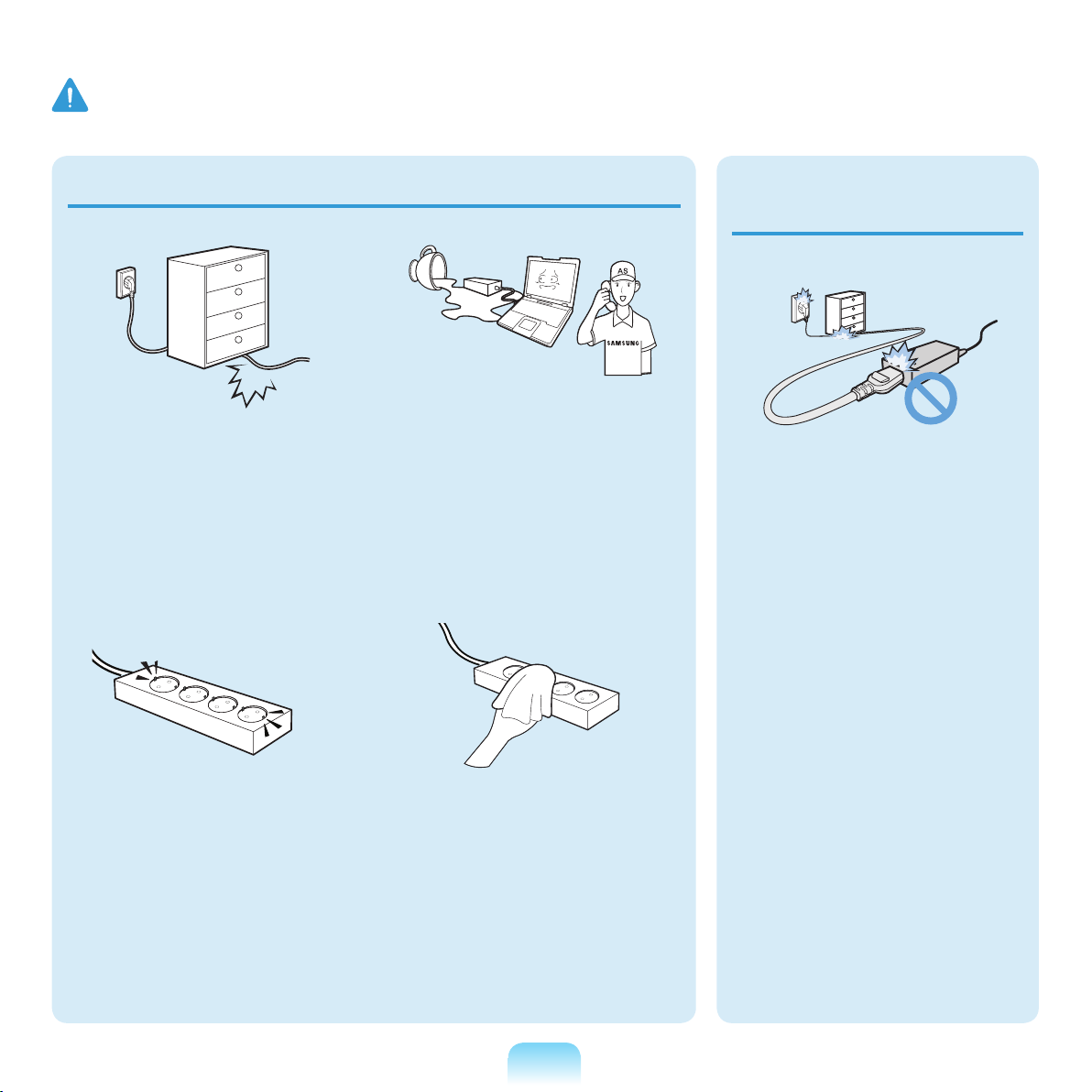
Do not use a damaged or loose
main plug or power cord or power
outlet.
There is a danger of electric shock or
re hazard.
Plug the power cord rmly into the
power outlet and AC adapter.
Failing to do so may cause re hazard.
Do not unplug the power cord out
by pulling the cable only.
If the cord is damaged, it may cause
electric shock.
8
Page 9
Warning
Failing to follow instructions marked with this symbol may cause personal injury and even fatality.
Do not bend the power cord
excessively or do not place a heavy
object over the power cord. It is
especially important to keep the
power cord out of reach of infants
and pets.
If the cord is damaged, it may cause
electric shock or re.
If water or another substance enters
the power input jack, AC adapter or
the computer, disconnect the power
cord and contact the service center.
Damage to the device within the
computer may cause electric shock or
re hazard.
AC Adapter Usage
Precautions
Do not place heavy objects or step
onto the power cord or AC adapter
to avoid damaging the power cord
or AC adapter.
If the cord is damaged, there is a
danger of electric shock or re.
Use only the AC adapter supplied
with the product.
Using another adapter may cause the
screen to icker.
Keep the power cord or outlet clean
so that they are not covered with
dust.
Failing to do so may result in re.
Connect the power cord to an outlet
or multiple power plug (extended
cable) with a ground terminal.
Failing to do so may result in electric
shock.
9
Page 10
Warning
Failing to follow instructions marked with this symbol may cause personal injury and even fatality.
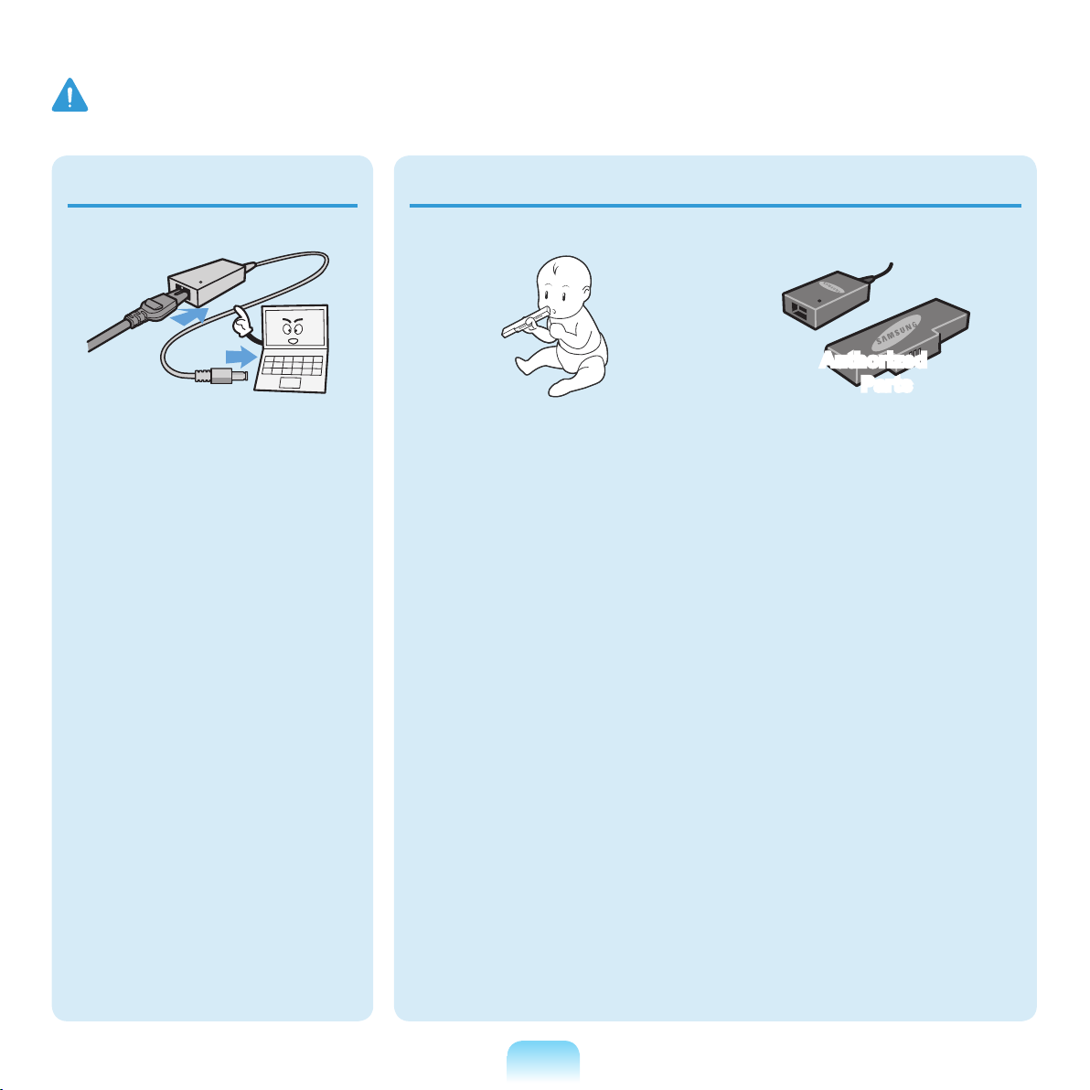
Connect the power cord to the AC
adapter rmly.
Otherwise, there is a danger of re due
to an incomplete contact.
Battery Usage Related
Keep the battery out of the reach of
infants and pets, as they could put
the battery into their mouths.
There is a danger of electric shock or
choking.
Authorized
Parts
Use an authorized battery and AC
adapter only.
Please use an authorized battery
and adapter approved by Samsung
Electronics.
Unauthorized batteries and adapters
may not meet the proper safety
requirements and may cause problems
or malfunctions and result in an
explosion or re.
10
Page 11
Warning
Failing to follow instructions marked with this symbol may cause personal injury and even fatality.
Power Off
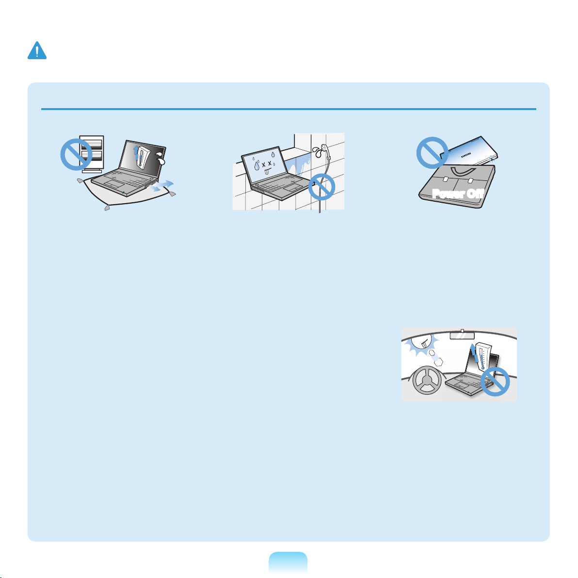
Do not use the computer in a badly
ventilated location such as on
bedding, on a pillow or cushion, etc,
and do not use it in a location such
as room with oor heating as it may
cause the computer to overheat.
Take care that the computer vents (on
the side or the bottom) are not blocked
especially in these environments. If the
vents are blocked, the computer may
overheat and it may cause a computer
problem, or even an explosion.
Do not use the computer in a humid
location such as a bathroom or
sauna.
Please use the computer within the
recommended temperature and
humidity range (10~35ºC, 20~80%
RH).
Do not close the LCD panel and put
the computer into your bag to move
it when it is still turned on.
If you put the computer into your bag
without turning it off, the computer
may overheat and there is a danger of
re. Shut the computer down properly
before moving it.
Never heat the battery or put the
battery into a re. Do not put or use
the battery in a hot location such as
a sauna, inside a vehicle exposed to
the heat, and so on.
There is a danger of an explosion or
re.
11
Page 12
Warning
Failing to follow instructions marked with this symbol may cause personal injury and even fatality.
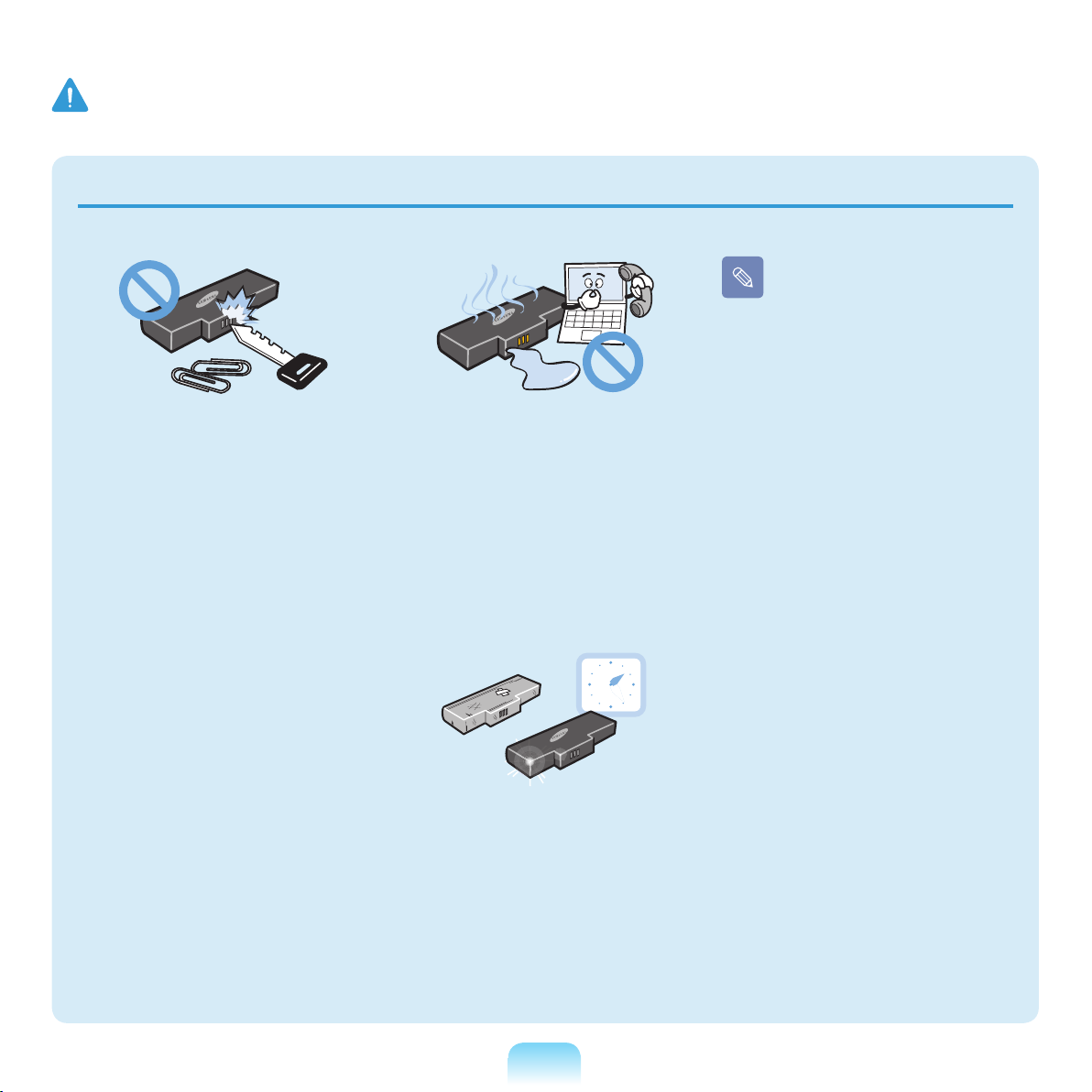
Please charge the battery
fully before using the
computer for the rst time.
Take care not to allow metal objects
such as a key or clip to touch the
battery terminal (metal parts).
If a metal object touches the battery
terminals, it may cause excessive
current ow and it may damage the
battery, or result in a re.
If liquid leaks out of the battery or
there is a funny smell coming from
the battery, remove the battery from
the computer and contact a service
center.
There is a danger of an explosion or
re.
To use the computer safely,
replace a dead battery with a new,
authorized battery.
12
Page 13
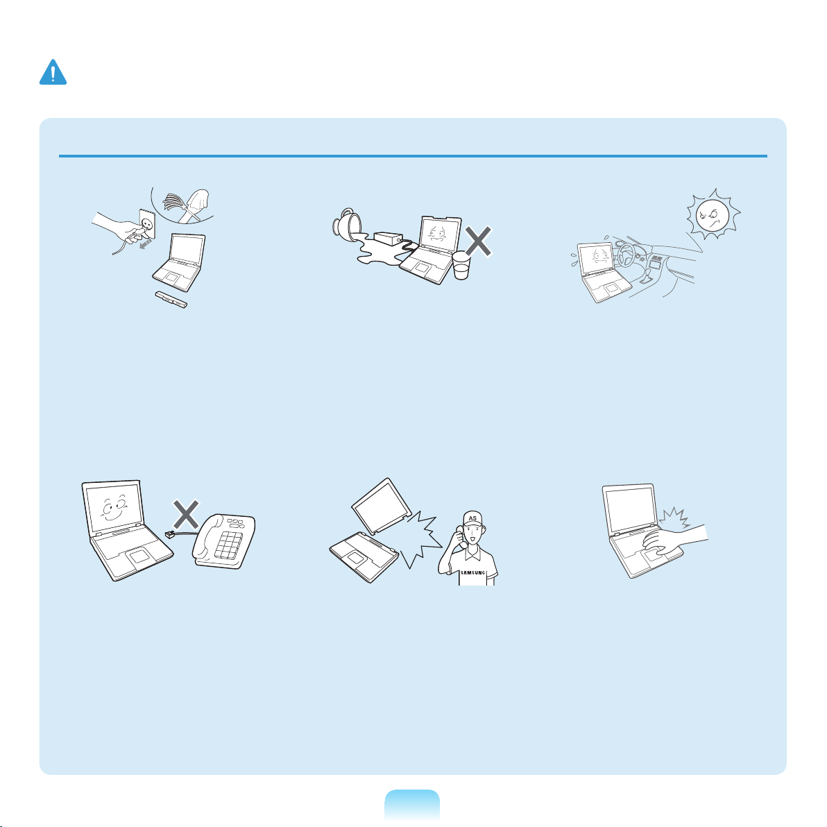
Warning
Failing to follow instructions marked with this symbol may cause personal injury and even fatality.
Usage Related
Disconnect all cables connected
to the computer before cleaning
it. If you are cleaning a notebook
computer, remove the battery.
There is a danger of electric shock or
damage to the product.
Do not connect a phone line
connected to a digital phone to the
modem.
There is a danger of a electric shock,
re or damage to the product.
Do not place any container lled
with water or chemicals over or near
the computer.
If water or chemicals enter the
computer, this may cause re or
electric shock.
If the computer is broken or
dropped, disconnect the power cord
and contact a service center for a
safety check.
Using a broken computer may cause
electric shock or re hazard.
Avoid direct sunlight when the
computer is in an air-tight location
such as inside a vehicle.
There is a danger of a re hazard.
The computer may overheat and also
present opportunity to thieves.
Do not use your notebook PC for
long periods of time while a part of
your body is making direct contact
with it. The temperature of the
product may increase during normal
operation.
This may result in harming or burning
your skin.
13
Page 14
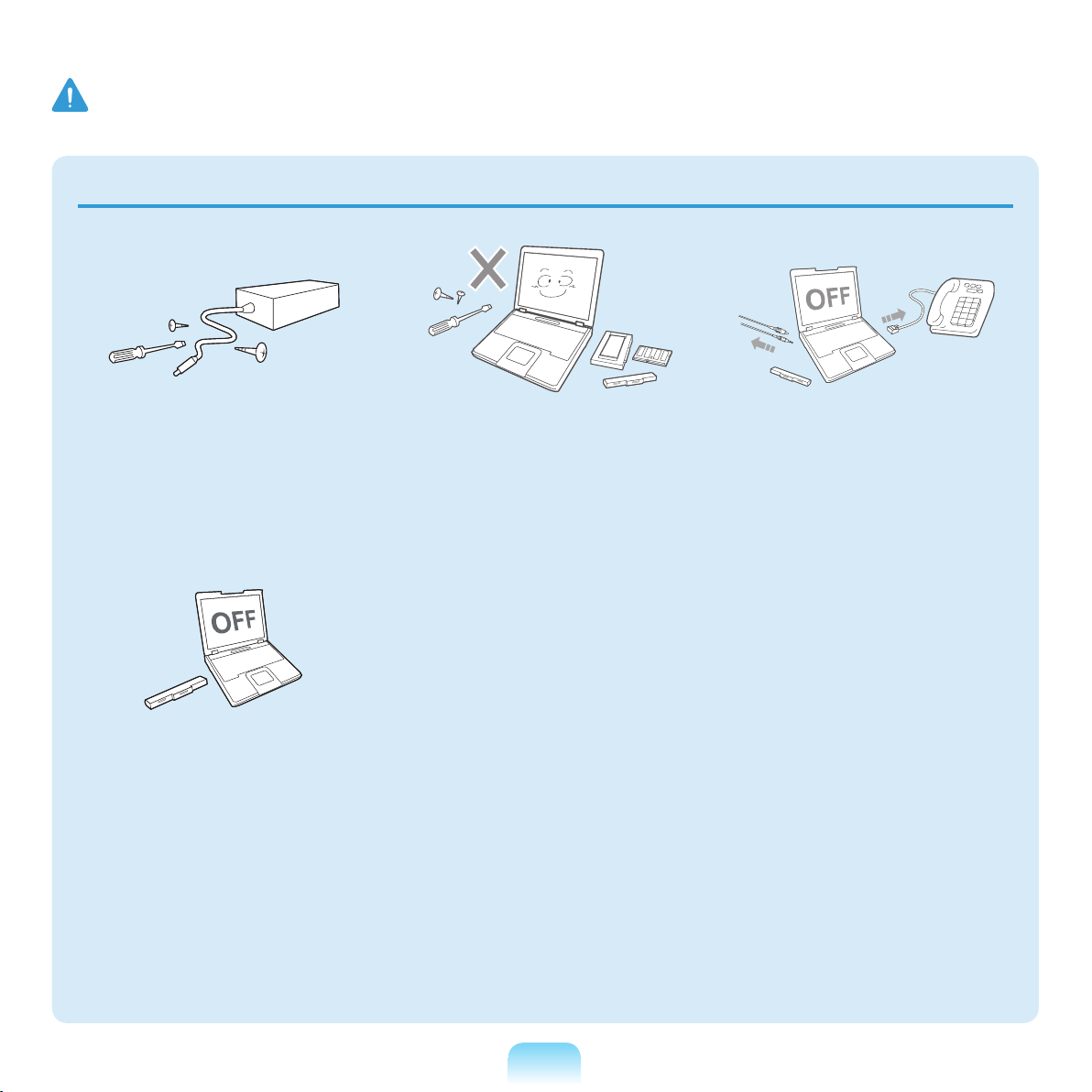
Warning
Failing to follow instructions marked with this symbol may cause personal injury and even fatality.
Upgrade Related
Never disassemble the power
supply or AC adapter.
There is a danger of electric shock.
When removing the RTC (Real Time
Clock) battery, keep it out of the
reach of children as they could
touch and/or swallow it.
There is a danger of choking. If a child
has swallowed it, contact a doctor
immediately.
Use only authorized parts (multiplug, battery and memory) and
never disassemble parts.
There is a danger of damaging the
product, electric shock or re hazard.
Shut down the computer and
disconnect all cables before
disassembling the computer. If
there is a modem, disconnect the
phone line. If you are disassembling
notebook computer, make sure to
remove the battery.
Failing to do so, may cause electric
shock.
14
Page 15
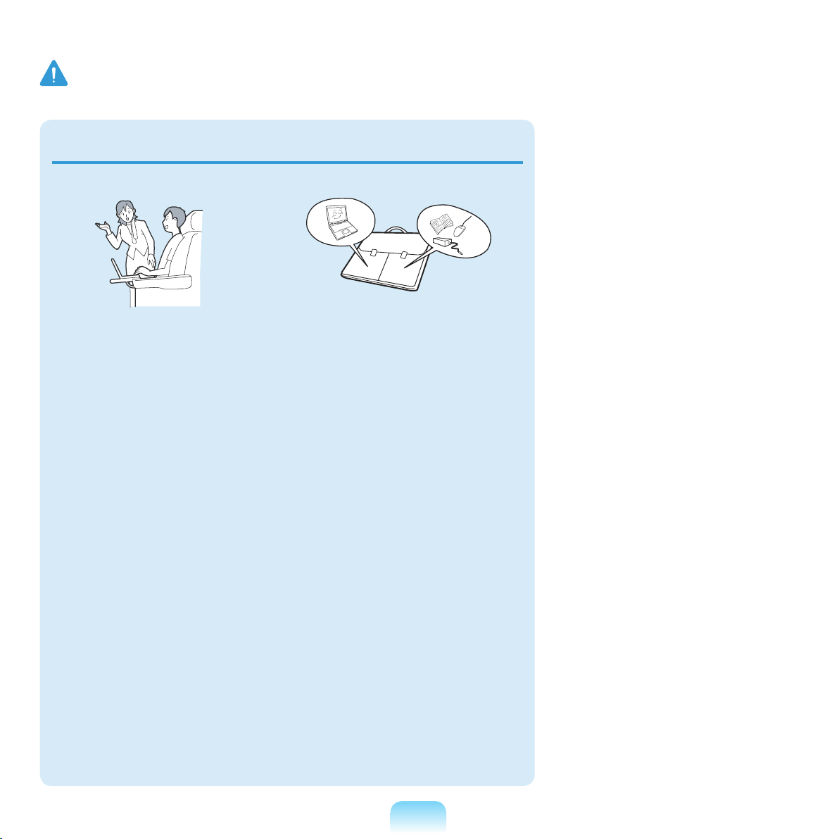
Warning
Failing to follow instructions marked with this symbol may cause personal injury and even fatality.
Custody and Movement Related
Follow the instructions for the
relevant location (e.g. airplane,
hospital, etc.) when using a wireless
communication device (wireless
LAN, Bluetooth, etc.).
When carrying the notebook
computer with other items, such as
the adapter, mouse, books etc, take
care not to press anything against
the notebook computer.
If a heavy object is pressed against
the notebook computer, a white spot
or stain may appear on the LCD.
Therefore, take care not to apply any
pressure to the notebook.
In this case, place the notebook
computer in a separate compartment
away from the other objects.
15
Page 16

Caution
Failing to follow instructions marked with this symbol may cause slight injury or damage to the product.
Installation Related
Do not block the ports (holes),
vents, etc. of the product and do not
insert objects.
Damage to a component within the
computer may cause electric shock or
re.
When using the computer with it
lying on its side, place it so that the
vents face upwards.
Failing to do so, may cause the internal
temperature of the computer to rise
and the computer to malfunction or
halt.
Do not place a heavy object over the
product.
This may cause a problem with the
computer. In addition, the object may
fall and cause injury, or damage the
computer.
Battery Usage Related
Dispose of worn-out batteries
properly.
There is a danger of re or explosion.
The battery disposal method may
differ depending on your country and
region. Dispose of the used battery in
an appropriate way.
Do not throw or disassemble the
battery and do not put it into water.
This may cause an injury, re or
explosion.
Use only a battery authorized by
Samsung Electronics.
Failing to do so may cause an
explosion.
Avoid contact with metal objects
such as car keys or clips when
keeping or carrying a battery.
Contact with a metal may cause
excessive current and a high
temperature and may damage the
battery or cause a re.
Charge the battery according to the
instructions in the manual.
Failing to do so, may cause an
explosion or re from damage to the
product.
Do not heat the battery or expose it
to heat (e.g. inside a vehicle during
the summer).
There is a danger of explosion or re.
16
Page 17

Caution
Failing to follow instructions marked with this symbol may cause slight injury or damage to the product.
Usage Related
Do not place a candle, light cigar,
etc. over or on the product.
There is a danger of re.
Use a wall outlet or multi-plug with
a grounding part.
Failing to do so may cause electric
shock hazard.
Make sure to have the product
tested by a safety service engineer
after repairing the product.
Authorized Samsung Repair Centers
will carry out safety checks after a
repair. Using a repaired product without
testing it for safety may cause an
electric shock or re.
In case of lightning, immediately
turn the system off, disconnect the
power cord from the wall outlet and
phone line from modem. Do not use
a modem or phone.
There is a danger of electric shock or
re.
Do not use your computer and
AC-Adapter on your lap or soft
surfaces.
If the computer temperature increases,
there is a danger of burning yourself.
Connect only permitted devices
to the connectors or ports of the
computer.
Failing to do so, may cause electric
shock and re.
Close the LCD panel only after
checking if the notebook computer
is turned off.
The temperature may rise and it may
cause overheating and deformation of
the product.
Do not press the Eject Button while
the Floppy Disk/CD-ROM drive is in
operation.
You might lose data and the disk might
be suddenly ejected and could cause
an injury.
Take care not to drop the product
while using it.
This may cause personal injury or loss
of data.
Do not touch the antenna with
electricity facility such as the power
outlet.
There is a danger of electric shock.
When handling computer parts,
follow the instructions on the
manual supplied with the parts.
Failing to do so, may cause damage to
the product.
17
Page 18

Caution
Failing to follow instructions marked with this symbol may cause slight injury or damage to the product.
If the computer emits smoke, or
there is a burning smell, disconnect
the power plug from the wall outlet
and contact a service center. If your
computer is a notebook computer,
make sure to remove the battery.
There is a danger of re.
Do not use a damaged or modied
CD/Floppy Disk.
There is a danger of damaging the
product or personal injury.
Do not insert your ngers into the
PC Card Slot.
There is a danger of injury or electric
shock.
Use recommended computer
cleansing solution when cleaning
the product and only use the
computer when it is completely
dried.
Failing to do so may cause electric
shock or re.
Emergency disk eject method using
paperclip should not be used while
the disk is in motion. Make sure
to use the emergency disk eject
method only when the Optical Disk
Drive is stopped.
There is a danger of injury.
Do not place your face close to the
Optical Disk Drive tray when it is
operating.
There is a danger of injury due to an
abrupt ejection.
Check CDs for cracks and damage
prior to use.
It may damage the disc and cause
disorder of device and injury of user.
18
Page 19

Caution
Failing to follow instructions marked with this symbol may cause slight injury or damage to the product.
Upgrade Related
Take care when touching the
product or parts.
The device may be damaged or you
may be injured.
Take care not to throw or drop a
computer part or device.
This may cause injury or damage to the
product.
Make sure to close the computer
cover before connecting the power
after a reassembly.
There is a danger of electric shock if
your body touches an internal part.
Use parts authorized by Samsung
Electronics only.
Failing to do so, may cause re or
damage the product.
Never disassemble or repair the
product by yourself.
There is a danger of electric shock or
re.
To connect a device that is not
manufactured or authorized by
Samsung Electronics, enquire
at your service center before
connecting the device.
There is a danger of damaging the
product.
Custody and Movement
Related
When moving the product, turn
the power off and separate all
connected cables rst.
The product might be damaged or
users may trip over the cables.
For long periods of not using the
notebook computer, discharge
the battery and preserve as it is
detached.
The battery will be preserved at its best
condition.
Do not operate or watch the
computer while driving a vehicle.
There is a danger of a trafc accident.
Please concentrate on driving.
19
Page 20

Caution
Failing to follow instructions marked with this symbol may cause slight injury or damage to the product.
Cautions on Preventing Data Loss (Hard Disk Management)
Take care not to damage the data on a hard disk drive.
A hard disk drive is so sensitive to external impact that an external impact may cause loss of data on the surface of the
disk.
Take extra care, because moving the computer or an impact on the computer when it is turned on may damage the data of
the hard disk drive.
The company is not liable for any loss of any data caused by a customer’s careless usage or bad environmental conditions.
Causes that may damage the data of a hard disk drive and the hard disk drive itself.
The data may be lost when an external impact is applied to the disk while disassembling or assembling the computer.
The data may be lost when the computer is turned off or reset by a power failure while the hard disk drive is operating.
The data may be lost and irrecoverable due to a computer virus infection.
The data may be lost if the power is turned off while running a program.
Moving or causing an impact to the computer while the hard disk drive is operating, may cause les to be corrupted or bad
sectors on the hard disk.
To prevent data loss due to damage to the hard disk drive, please backup your data frequently.
20
Page 21
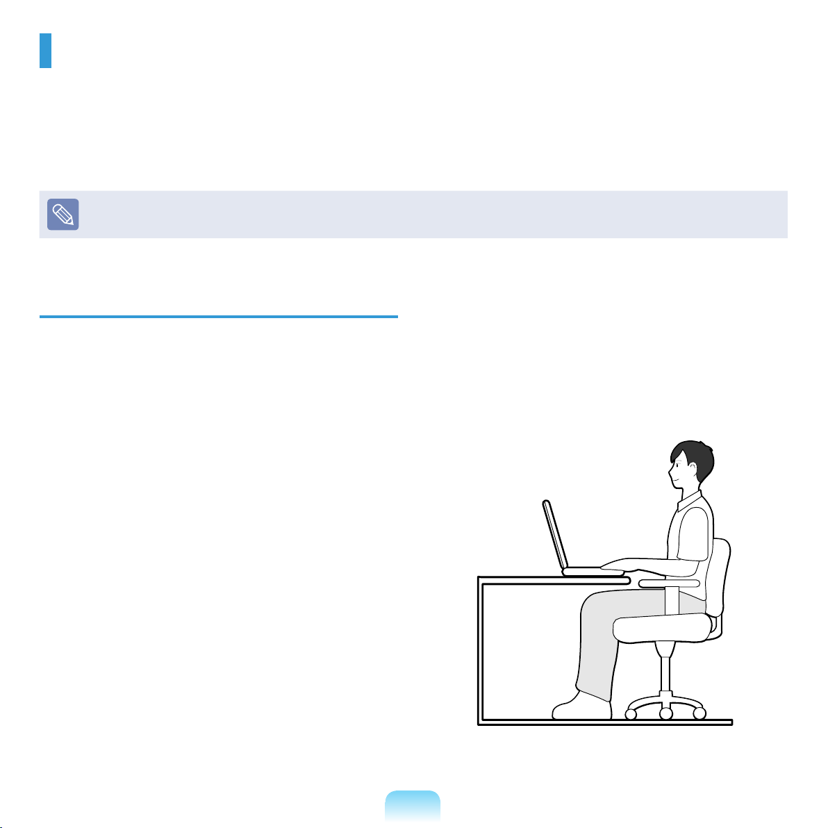
Proper Posture During Computer Use
Maintaining a proper posture during computer use is very important to prevent physical harm.
The following instructions are about maintaining a proper posture during computer use developed through human
engineering. Please read and follow them carefully when using the computer.
Otherwise, the probability of (RSI: Repetitive Strain Injury) from repeated operations may increase and serious
physical harm may be caused.
The instructions in this manual have been prepared so that they can be applied within the coverage of general users.
If the user is not included in the coverage, the recommendation is to be applied according to the user’s needs.
To use the computer while talking over the telephone,
Proper Posture
Adjust the heights of desks and chairs appropriate to
your height.
The heights are to be adjusted so that your arm forms a
right angle when you place your hand over the keyboard
while sitting down on a chair.
Adjust the height of chair so that your heel is comfortably
placed on the oor.
use a headset. Using the computer with the phone on
your shoulder is bad for posture.
Keep frequently used items within a comfortable work
range (where you can reach them with your hands).
Do not use the computer while you are lying down, but
only while you are sitting down.
Do not use the computer on your lap. If the computer
temperature increases, there is a danger of burning
yourself.
Work while keeping your waist straight.
Use a chair with a comfortable back.
Keep the center of your leg weight not on the chair but
on your feet when you are sitting on a chair.
21
Page 22
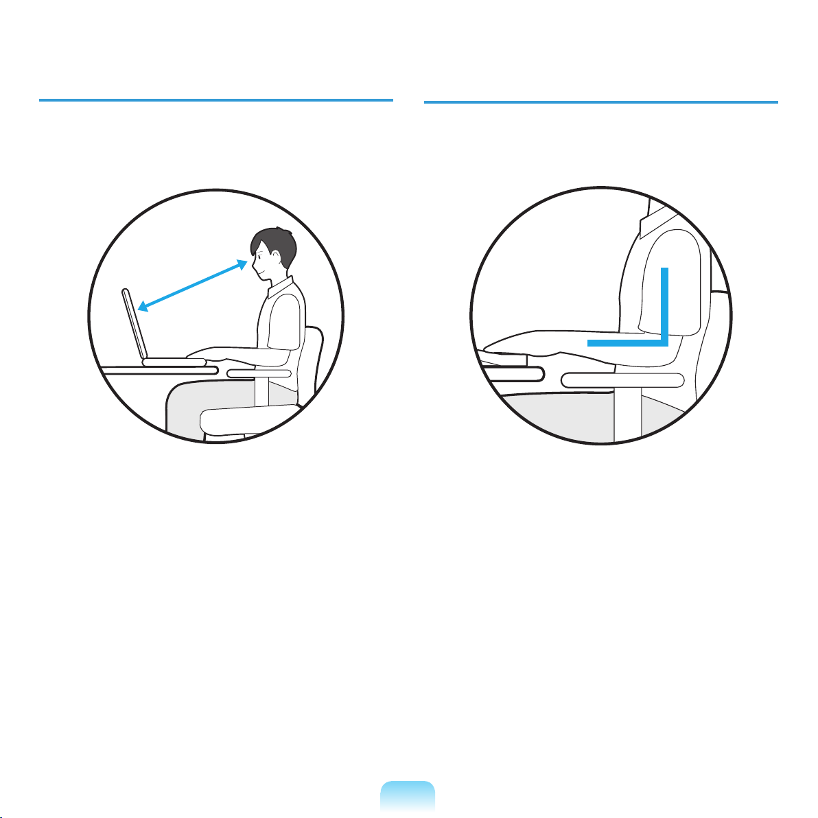
Eye Position
Hand Position
Keep the monitor or LCD away from your eyes by at
least 50cm.
50cm
Adjust the height of the monitor and the LCD screen so
that its top height is equal to or lower than your eyes.
Avoid setting the monitor and LCD excessively bright.
Keep the monitor and LCD screen clean.
If you wear glasses, clean them before using the
computer.
When entering contents printed on a paper into the
computer, use a static paper holder so that the height
of the paper is almost equal to that of the monitor.
Keep your arm at a right angle as shown by the
gure.
Keep the line from your elbow to your hand straight.
Do not place your palm over the keyboard while typing.
Do not hold the mouse with excessive force.
Do not press the keyboard, touchpad or mouse with
excessive force.
It is recommended connecting an external keyboard
and mouse when using the computer for long periods
of time.
22
Page 23
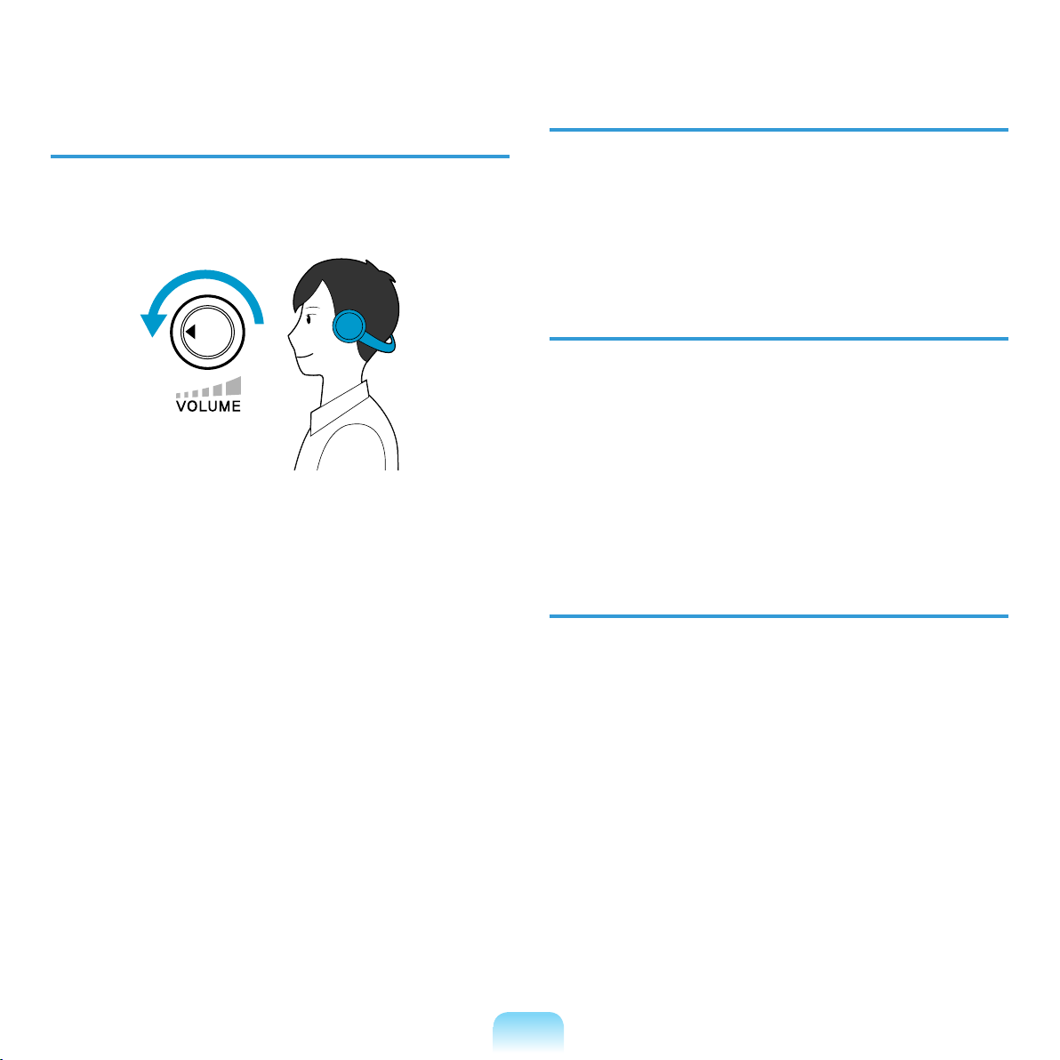
Volume Control
(Headphones and Speakers)
Check your volume rst to listen to music.
Check your
volume!!
Check if the volume is too loud before using
headphones.
It is not recommended using headphones for long
periods of time.
Any deviation from the equalizer default setting could
cause hearing impairment.
The default setting can be changed through software
and driver updates without your intervention. Please
check the equalizer default setting before rst usage.
Use Time (Break Time)
Take a break for 10 minutes or more after a 50-minute
period when working for more than one hour.
Illumination
Do not use the computer in dark locations. The
illumination level for computer use must be as bright
so for reading a book.
Indirect illumination is recommended. Use a curtain to
prevent reection on the LCD screen.
Operation Condition
Do not use the computer in hot and humid locations.
Use the computer within the allowed temperature and
humidity range specied in the User Guide.
23
Page 24
Important Safety Information
Safety Instructions
Your system is designed and tested to meet the latest
standards for safety of information technology equipment.
However, to ensure safe use of this product, it is important
that the safety instructions marked on the product and in
the documentation are followed.
Always follow these instructions to help guard against
personal injury and damage to your system.
Setting Up your System
Read and follow all instructions marked on the product
and in the documentation before you operate your
system. Retain all safety and operating instructions for
future use.
Do not use this product near water or a heat source
such as a radiator.
Set up the system on a stable work surface.
The product should be operated only with the type of
power source indicated on the rating label.
Ensure that the electrical outlet you are using to power
your equipment is easily accessible in case of re or
short circuit.
If your computer has a voltage selector switch, make
sure that the switch is in the proper position for your
area.
Openings in the computer case are provided for
ventilation. Do not block or cover these openings.
Make sure you provide adequate space, at least 6
inches (15 cm), around the system for ventilation when
you set up your work area. Never insert objects of any
kind into the computer ventilation openings.
Ensure that the fan vents on the bottom of the casing
are clear at all times. Do not place the computer on a
soft surface, doing so will block the bottom vents.
If you use an extension cord with this system, make
sure that the total power rating on the products
plugged into the extension cord does not exceed the
extension cord power rating.
24
Page 25

Care During Use
Do not walk on the power cord or allow anything to rest
on it.
Do not spill anything on the system. The best way to
avoid spills is to not eat or drink near your system.
Some products have a replaceable CMOS battery
on the system board. There is a danger of explosion
if the CMOS battery is replaced incorrectly. Replace
the battery with the same or equivalent type
recommended by the manufacturer.
Dispose of batteries according to the manufacturers
instructions. If the CMOS battery requires replacement
insure that a qualied technician performs the task.
When the computer is turned off, a small amount of
electrical current still ows through the computer.
To avoid electrical shock, always unplug all power
cables, remove the battery and modem cables from
the wall outlets before cleaning the system.
Unplug the system from the wall outlet and refer
servicing to qualied personnel if:
– The power cord or plug is damaged.
– Liquid has been spilled into the system.
– The system does not operate properly when the
operating instructions are followed.
– The system was dropped or the casing is damaged.
– The system performance changes.
The Instruction On Safety Operation of
NotePC
z When installing and operating devices please refer to
safety requirements in the user guide.
x Devices can be used only with the equipment
specied in the technical specications of the devices.
c If any smell of burning or smoke is detected from the
computer the unit should be switched off and battery
removed. The unit should be checked by a qualied
technician before reuse.
v Service and repair of devices should be carried out by
authorized service centers.
b Do not allow your portable computer to operate with
the base resting directly on exposed skin for extended
periods of time. The surface temperature of the base
will rise during normal operation (particularly when
AC Power is present). Allowing sustained contact with
exposed skin can cause discomfort or eventually a
burn.
25
Page 26

Replacement Parts and Accessories
Use only replacement parts and accessories recommended by manufacturer.
To reduce the risk of re, use only No. 26 AWG or larger telecommunications line cord.
Do not use this product in areas classied as hazardous. Such areas include patient care areas of medical and dental facilities,
oxygen rich environments, or industrial areas.
Battery Disposal
Do not put rechargeable batteries or products powered
by non-removable rechargeable batteries in the
garbage.
Contact the Samsung Helpline for information on how to
dispose of batteries that you cannot use or recharge any
longer.
Follow all local regulations when disposing of old
batteries.
THERE IS A RISK OF EXPLOSION IF BATTERY IS
REPLACED BY AN INCORRECT TYPE.
DISPOSE OF USED BATTERIES ACCORDING TO
THE INSTRUCTIONS.
Laser Safety
All systems equipped with CD or DVD drives comply with
the appropriate safety standards, including IEC 60825-
1. The laser devices in these components are classied
as “Class 1 Laser Products” under a US Department
of Health and Human Services (DHHS) Radiation
Performance Standard. Should the unit ever need
servicing, contact an authorized service location.
Laser Safety Note:
Use of controls or adjustments or performance of
procedures other than those specied in this manual
may result in hazardous radiation exposure. To
prevent exposure to laser beams, do not try to open
the enclosure of a CD or DVD drive.
Class 1M laser radiation when operating part is
open.
Do not view directly with optical instruments.
Class 3B invisible laser radiation when open.
Avoid exposure to the beam.
26
Page 27

Connect and Disconnect the AC
adapter
The socket-outlet shall be installed near the equipment
and shall be easily accessible.
Do not unplug the power cord out by pulling the
cable only.
Power Cord Requirements
The power cord set (wall plug, cable and AC adapter plug)
you received with your computer meets the requirements
for use in the country where you purchased your
equipment.
Power cord sets for use in other countries must meet the
requirements of the country where you use the computer.
For more information on power cord set requirements,
contact your authorized dealer, reseller, or service
provider.
General Requirements
The requirements listed below are applicable to all
countries:
All power cord sets must be approved by an
acceptable accredited agency responsible for
evaluation in the country where the power cord set will
be used.
The power cord set must have a minimum current
capacity of 7 A and a nominal voltage rating of 125
or 250 volts AC, as required by each country’s power
system. (USA ONLY)
The appliance coupler must meet the mechanical
conguration of an EN 60 320/IEC 320 Standard
Sheet C7(or C5) connector, for mating with appliance
inlet on the computer.
27
Page 28

Regulatory Compliance Statements
Wireless Guidance
(If tted with 2.4G band or 5G band)
Low power, Radio LAN type devices (radio frequency (RF) wireless communication devices), operating in the 2.4GHz/
5GHz Band, may be present (embedded) in your notebook system. The following section is a general overview of
considerations while operating a wireless device.
Additional limitations, cautions, and concerns for specic countries are listed in the specic country sections (or country
group sections). The wireless devices in your system are only qualied for use in the countries identied by the Radio
Approval Marks on the system rating label. If the country you will be using the wireless device in, is not listed, please
contact your local Radio Approval agency for requirements. Wireless devices are closely regulated and use may not be
allowed.
The RF eld strength of the wireless device or devices that may be embedded in your notebook are well below all
international RF exposure limits as known at this time. Because the wireless devices (which may be embedded into your
notebook) emit less energy than is allowed in radio frequency safety standards and recommendations, manufacturer
believes these devices are safe for use. Regardless of the power levels, care should be taken to minimize human contact
during normal operation.
As a general guideline, a separation of 20 cm (8 inches) between the wireless device and the body, for use of a wireless
device near the body (this does not include extremities) is typical. This device should be used more than 20 cm (8 inches)
from the body when wireless devices are on and transmitting.
Some circumstances require restrictions on wireless devices. Examples of common restrictions are listed on the next
page:
28
Page 29

Radio frequency wireless communication can interfere with equipment on commercial aircraft. Current aviation regulations
require wireless devices to be turned off while traveling in an airplane.
802.11ABGN (also known as wireless Ethernet or Wi) and Bluetooth communication devices are examples of devices that
provide wireless communication.
In environments where the risk of interference to other devices or services is harmful or perceived as harmful, the option to
use a wireless device may be restricted or eliminated. Airports, Hospitals, and Oxygen or ammable gas laden atmospheres
are limited examples where use of wireless devices may be restricted or eliminated. When in environments where you are
uncertain of the sanction to use wireless devices, ask the applicable authority for authorization prior to use or turning on the
wireless device.
Every country has different restrictions on the use of wireless devices. Since your system is equipped with a wireless device,
when traveling between countries with your system, check with the local Radio Approval authorities prior to any move or trip
for any restrictions on the use of a wireless device in the destination country.
If your system came equipped with an internal embedded wireless device, do not operate the wireless device unless all covers
and shields are in place and the system is fully assembled.
Wireless devices are not user serviceable. Do not modify them in any way. Modication to a wireless device will void the
authorization to use it. Please contact manufacturer for service.
Only use drivers approved for the country in which the device will be used. See the manufacturer System Restoration Kit, or
contact manufacturer Technical Support for additional information.
29
Page 30

United States of America
USA and Canada Safety Requirements
and Notices
Do not touch or move antenna while the unit is
transmitting or receiving.
Do not hold any component containing the radio such
that the antenna is very close or touching any exposed
parts of the body, especially the face or eyes, while
transmitting.
Do not operate the radio or attempt to transmit data
unless the antenna is connected; if not, the radio may be
damaged.
Use in specic environments:
The use of wireless devices in hazardous locations is
limited by the constraints posed by the safety directors of
such environments.
The use of wireless devices on airplanes is governed by
the Federal Aviation Administration (FAA).
The use of wireless devices in hospitals is restricted to
the limits set forth by each hospital.
Other Wireless Devices
Safety Notices for Other Devices in the Wireless
Network: Refer to the documentation supplied with
wireless Ethernet adapters or other devices in the
wireless network.
The Part 15 radio device operates on a noninterference basis with other devices operating at this
frequency. Any changes or modication to said product
not expressly approved by Intel could void the user’s
authority to operate this device.
Explosive Device Proximity Warning
Do not operate a portable transmitter (such as a
wireless network device) near unshielded blasting caps
or in an explosive environment unless the device has
been modied to be qualied for such use.
Use On Aircraft Caution
Regulations of the FCC and FAA prohibit airborne
operation of radio-frequency wireless devices because
their signals could interfere with critical aircraft
instruments.
30
Page 31

Unintentional Emitter per FCC Part 15
This device complies with Part 15 of the FCC Rules.
Operation is subject to the following two conditions:(1) this
device may not cause harmful interference, and (2) this
device must accept any interference received, including
interference that may cause undesired operation.
This equipment has been tested and found to comply
with the limits for a Class B digital device pursuant to
Part 15 of the FCC Rules. These limits are designed
to provide reasonable protection against harmful
interference in a residential installation. This equipment
generates, uses, and can radiate radio frequency
energy. If not installed and used in accordance with
the instructions, it may cause harmful interference.
If this equipment does cause harmful interference to
radio or television reception, which can be determined
by turning the equipment off and on, the user is
encouraged to try to correct the interference by one or
more of the following measures:
Reorient or relocate the receiving antenna.
Increase the separation between the equipment and
receiver.
Connect the equipment into an outlet on a
circuit different from that to which the receiver is
connected.
Consult the dealer or an experienced radio/TV
technician for help.
If necessary, the user should consult the dealer or an
experienced radio/television technician for additional
suggestions. The user may nd the following booklet
helpful: “Something About Interference.”
This is available at FCC local regional ofces. Our
company is not responsible for any radio or television
interference caused by unauthorized modications of this
equipment or the substitution or attachment of connecting
cables and equipment other than those specied by our
company. The correction will be the responsibility of the
user. Use only shielded data cables with this system.
31
Page 32

Intentional emitter per FCC Part 15
(If tted with 2.4G band or 5G band)
Low power, Radio LAN type devices (radio frequency
(RF) wireless communication devices), operating in the
2.4GHz/5GHz Band, may be present (embedded) in your
notebook system. This section is only applicable if these
devices are present. Refer to the system label to verify
the presence of wireless devices.
Wireless devices that may be in your system are only
qualied for use in the United States of America if an FCC
ID number is on the system label.
This device is restricted to indoor use due to its operation
in the 5.15 to 5.25 GHz frequency range. FCC requires
this product to be used indoors for the frequency range
5.15 to 5.25 GHz to reduce the potential for harmful
interference to co-channel Mobile Satellite systems. High
power radars are allocated as primary users of the 5.25
to 5.35 GHz and 5.65 to 5.85 GHz bands. These radar
stations can cause interference with and /or damage this
device.
The FCC has set a general guideline of 20 cm (8 inches)
separation between the device and the body, for use of
a wireless device near the body (this does not include
extremities). This device should be used more than 20
cm (8 inches) from the body when wireless devices are
on. The power output of the wireless device (or devices),
which may be embedded in your notebook, is well below
the RF exposure limits as set by the FCC.
This transmitter must not be collocated or operate in
conjunction with any other antenna or transmitter except
the installed Bluetooth transmitter.
Operation of this device is subject to the following
two conditions: (1) This device may not cause harmful
interference, and (2) this device must accept any
interference received, including interference that may
cause undesired operation of the device.
Wireless devices are not user serviceable. Do not
modify them in any way.
Modication to a wireless device will void the
authorization to use it. Contact manufacturer for
service.
FCC Statement for Wireless LAN use:
“While installing and operating this transmitter and
antenna combination the radio frequency exposure limit
of 1mW/cm2 may be exceeded at distances close to the
antenna installed. Therefore, the user must maintain
a minimum distance of 20cm from the antenna at all
times.
This device can not be colocated with another
transmitter and transmitting antenna.”
32
Page 33

FCC Part 68
(If tted with a modem device.)
This equipment compiles with part of the FCC rules.
On the back of this equipment is a label that contains,
among other information, the FCC registration number
and ringer equivalence number (REN) for this equipment.
If requested, this information must be provided to the
telephone company.
This equipment uses the following USOC jacks : RJ11C
An FCC compliant telephone cord and modular plug is
provided with this equipment. This equipment is designed
to be connected to the telephone network or promises
wiring using a compatible modular jack which is Part 68
compliant. See Installation Instructions for details.
The REN is used to determine the quantity of devices
which may be connected to telephone line. Excessive
RENs on the telephone line may result in the devices
not ringing in response to an incoming call. In most, but
not all areas, the sum of RENs should not exceed ve
(5.0). To be certain of the number of devices that may be
connected to a line, as determined by total RENs, contact
the local telephone company to determine the maximum
REN for the calling area.
If the terminal equipment causes harm to the telephone
network, the Telephone Company will notify you in
advance that temporary discontinuance of service may
be required. But if advance notice is not practical, the
telephone company will notify the customer as soon as
possible. Also, you will be advised of your right to le a
complaint with the FCC if you believe it is necessary.
The telephone company may make changes in its
facilities, equipment, operations, or procedures that could
affect the operation of the equipment. If this happens,
the telephone company will provide advanced notice in
order for you to make necessary modications to maintain
uninterrupted service.
If trouble is experienced with this equipment (Modem)
for repair or warranty information, please contact your
local distributor. If the equipment is causing harm to the
telephone network, the telephone company may request
that you disconnect the equipment until the problem is
resolved.
The user must use the accessories and cables supplied
by the manufacturer to get optimum performance from the
product.
No repairs may be done by the customer.
This equipment cannot be used on public coin phone
service provided by the telephone company. Connection
to party line service is subject to state tariffs.
The Telephone Consumer Protection Act of 1991 makes
it unlawful for any person to use a computer or other
electronic device, including fax machines, to send any
message unless such message clearly contains in a
margin at the top or bottom of each transmitted page
or on the rst page of the transmission, the date and
time it is sent and an identication of the business or
other entity, or other individual sending the message
and the telephone number of the sending machine or
such business, other entity, or individual. (The telephone
number provided may not be any number for which
charges exceed local or long-distance transmission
charges.)
In order to program this information into your fax machine,
refer to your communications software user manual.
33
Page 34

Canada
Unintentional Emitter per ICES-003
This digital apparatus does not exceed the Class B limits
for radio noise emissions from digital apparatus as set out
in the radio interference regulations of Industry Canada.
Le présent appareil numérique n’émet pas de bruits
radioélectriques dépassant les limitesapplicables aux
appareils numériques de Classe B prescrites dans le
règlement sur le brouillage radioélectrique édicté par
Industrie Canada.
Intentional Emitter per RSS 210
(If tted with 2.4G band or 5G band)
Low power, Radio LAN type devices (radio frequency
(RF) wireless communication devices), operating in the
2.4GHz/5GHz Band, may be present (embedded) in your
notebook system. This section is only applicable if these
devices are present. Refer to the system label to verify
the presence of wireless devices.
Wireless devices that may be in your system are only
qualied for use in Canada if an Industry Canada ID
number is on the system label.
When using IEEE 802.11a wireless LAN, this product is
restricted to indoor use due to its operation in the 5.15- to
5.25-GHz frequency range. Industry Canada requires
this product to be used indoors for the frequency range of
5.15 GHz to 5.25 GHz to reduce the potential for harmful
interference to co-channel mobile satellite systems. High
power radar is allocated as the primary user of the 5.25to 5.35-GHz and 5.65 to 5.85-GHz bands. These radar
stations can cause interference with and/or damage to
this device.
The maximum allowed antenna gain for use with this
device is 6dBi in order to comply with the E.I.R.P limit for
the 5.25- to 5.35 and 5.725 to 5.85 GHz frequency range
in point-to-point operation.
As a general guideline, a separation of 20 cm (8 inches)
between the wireless device and the body, for use of
a wireless device near the body (this does not include
extremities) is typical. This device should be used more
than 20 cm (8 inches) from the body when wireless
devices are on.
The power output of the wireless device (or devices),
which may be embedded in your notebook, is well below
the RF exposure limits as set by Industry Canada.
34
Page 35

This transmitter must not be collocated or operate in
conjunction with any other antenna or transmitter except
the installed Bluetooth transmitter.
Operation of this device is subject to the following
two conditions: (1) This device may not cause harmful
interference, and (2) this device must accept any
interference received, including interference that may
cause undesired operation of the device.
To prevent radio interference to licensed service, this
device is intended to be operated indoors and away from
windows to provide maximum shielding. Equipment (or
its transmit antenna) that is installed outdoors is subject
to licensing.
Wireless devices are not user serviceable. Do not modify
them in any way. Modication to a wireless device will
void the authorization to use it. Contact manufacturer for
service.
Telecommunications per DOC notice
(for products tted with an IC-compliant modem)
Repairs to certied equipment should be made by an
authorized Canadian maintenance facility designated by
the supplier. Any repairs or alterations made by the user
to this equipment, or equipment malfunctions, may give
the telecommunications company cause to request the
user to disconnect the equipment.
Users should make sure, for their own protection, that
the electrical ground connections of the power utility,
telephone lines, and internal metallic water pipe system, if
present, are connected together. This precaution may be
particularly important in rural areas.
To avoid electrical shock or equipment malfunction do
not attempt to make electrical ground connections by
yourself. Contact the appropriate inspection authority or
an electrician, as appropriate.
The Ringer Equivalence Number (REN) assigned
to each terminal device provides an indication of the
maximum number of terminals allowed to be connected
to a telephone interface. The termination on an interface
may consist of any combination of devices subject only to
the requirement that the sum of the Ringer Equivalence
Numbers of all the devices does not exceed 5.
The Industry Canada label identies certied equipment.
This certication means that the equipment meets certain
telecommunications network protective, operation, and
safety requirements. The Department does not guarantee
the equipment will operate to the users’ satisfaction.
Before installing this equipment, users should make sure
that it is permissible to be connected to the facilities of
the local telecommunications company. The equipment
must also be installed using an acceptable method of
connection. In some cases, the inside wiring associated
with a single-line individual service may be extended by
means of a certied connector assembly. The customer
should be aware that compliance with the above
conditions may not prevent degradation of service in
some situations.
35
Page 36
European Union
European Union CE Marking and
Compliance Notices
Products intended for sale within the European Union are
marked with the Conformité Européene (CE) Marking,
which indicates compliance with the applicable Directives
and European standards and amendments identied
below. This equipment also carries the Class 2 identier.
The following information is only applicable to systems
labeled with the CE mark
.
European Directives
This Information Technology Equipment has been
tested and found to comply with the following European
directives:
EMC Directive 2004/108/EC
Low Voltage Directive 2006/95/EC
R&TTE Directive 1999/5/EC
Manufacturer Information
European Radio Approval Information
(for products tted with EU-approved radio devices)
This Product is a Notebook computer; low power,
Radio LAN type devices (radio frequency (RF) wireless
communication devices), operating in the 2.4GHz/5GHz
band, may be present (embedded) in your notebook
system which is intended for home or ofce use. This
section is only applicable if these devices are present.
Refer to the system label to verify the presence of
wireless devices.
Wireless devices that may be in your system are only
qualied for use in the European Union or associated
areas if a CE mark
Number and the Alert Symbol is on the system label.
The power output of the wireless device or devices that
may be embedded in you notebook is well below the
RF exposure limits as set by the European Commission
through the R&TTE directive.
The low band 5.15 - 5.35 GHz is for indoor use only.
See 802.11b and 802.11g restrictions for specic
countries or regions within countries under the heading
“European Economic Area Restrictions” below.
with a Notied Body Registration
Samsung Electronics Co., Ltd.
416, Maetan-3Dong, Yeongtong-Gu, Suwon-City,
Gyeonggi-Do, 443-742, Korea
Samsung Electronics Suzhou Computer Co., Ltd.
No. 198, Fangzhou Road, Suzhou Industrial Park, Jiangsu
Province, 215021, China
Tel:+86-512-6253-8988
For the web or the phone number of Samsung Service
Centre, see the Warranty or contact the retailer where
you purchased your product.
36
Page 37
EU R&TTE Compliance Statements
Česky
[Czech]
Dansk
[Danish]
Deutsch
[German]
Eesti
[Estonian]
English
Español
[Spanish]
Ελληνική
[Greek]
Français
[French]
Italiano
[Italian]
Latviski
[Latvian]
Samsung tímto prohlašuje, že tento Notebook PC je ve shodě se základními požadavky a dalšími
příslušnými ustanoveními směrnice 1999/5/ES.
Undertegnede Samsung erklærer herved, at følgende udstyr Notebook PC overholder de væsentlige
krav og øvrige relevante krav i direktiv 1999/5/EF.
Hiermit erklärt Samsung, dass sich das Gerät Notebook PC in Übereinstimmung mit den
grundlegenden Anforderungen und den übrigen einschlägigen Bestimmungen der Richtlinie 1999/5/
EG bendet.
Käesolevaga kinnitab Samsung seadme Notebook PC vastavust direktiivi 1999/5/EÜ põhinõuetele ja
nimetatud direktiivist tulenevatele teistele asjakohastele sätetele.
Hereby, Samsung, declares that this Notebook PC is in compliance with the essential requirements
and other relevant provisions of Directive 1999/5/EC.
Por medio de la presente Samsung declara que el Notebook PC cumple con los requisitos esenciales
y cualesquiera otras disposiciones aplicables o exigibles de la Directiva 1999/5/CE.
ΜΕ ΤΗΝ ΠΑΡΟΥΣΑ Samsung ΔΗΛΩΝΕΙ ΟΤΙ Notebook PC ΣΥΜΜΟΡΦΩΝΕΤΑΙ ΠΡΟΣ ΤΙΣ
ΟΥΣΙΩΔΕΙΣ ΑΠΑΙΤΗΣΕΙΣ ΚΑΙ ΤΙΣ ΛΟΙΠΕΣ ΣΧΕΤΙΚΕΣ ΔΙΑΤΑΞΕΙΣ ΤΗΣ ΟΔΗΓΙΑΣ 1999/5/ΕΚ.
Par la présente Samsung déclare que l’appareil Notebook PC est conforme aux exigences
essentielles et aux autres dispositions pertinentes de la directive 1999/5/CE.
Con la presente Samsung dichiara che questo Notebook PC è conforme ai requisiti essenziali ed alle
altre disposizioni pertinenti stabilite dalla direttiva 1999/5/CE.
Ar šo Samsung deklarē, ka Notebook PC atbilst Direktīvas 1999/5/EK būtiskajām prasībām un citiem
ar to saistītajiem noteikumiem.
Lietuvių
[Lithuanian]
Nederlands
[Dutch]
Malti
[Maltese]
Magyar
[Hungarian]
Polski
[Polish]
Português
[Portuguese]
Šiuo Samsung deklaruoja, kad šis Notebook PC atitinka esminius reikalavimus ir kitas 1999/5/EB
Direktyvos nuostatas.
Hierbij verklaart Samsung dat het toestel Notebook PC in overeenstemming is met de essentiële
eisen en de andere relevante bepalingen van richtlijn 1999/5/EG.
Hawnhekk, Samsung, jiddikjara li dan Notebook PC jikkonforma mal-ħtiāijiet essenzjali u ma
provvedimenti oħrajn relevanti li hemm d-Dirrettiva 1999/5/EC.
Alulírott, Samsung nyilatkozom, hogy a Notebook PC megfelel a vonatkozó alapvetõ
követelményeknek és az 1999/5/EC irányelv egyéb elõírásainak.
Niniejszym Samsung oświadcza, Ŝe Notebook PC jest zgodny z zasadniczymi wymogami oraz
pozostałymi stosownymi postanowieniami Dyrektywy 1999/5/EC.
Samsung declara que este Notebook PC está conforme com os requisitos essenciais e outras
disposições da Directiva 1999/5/CE.
37
Page 38
Slovensko
[Slovenian]
Samsung izjavlja, da je ta Notebook PC v skladu z bistvenimi zahtevami in ostalimi relevantnimi
določili direktive 1999/5/ES.
Slovensky
[Slovak]
Suomi
[Finnish]
Svenska
[Swedish]
Íslenska
[Icelandic]
Norsk
[Norwegian]
Türkiye
[Türkçe]
Samsung týmto vyhlasuje, že Notebook PC spĺňa základné požiadavky a všetky príslušné
ustanovenia Smernice 1999/5/ES.
Samsung vakuuttaa täten että Notebook PC tyyppinen laite on direktiivin 1999/5/EY oleellisten
vaatimusten ja sitä koskevien direktiivin muiden ehtojen mukainen.
Härmed intygar Samsung att denna Notebook PC står I överensstämmelse med de väsentliga
egenskapskrav och övriga relevanta bestämmelser som framgår av direktiv 1999/5/EG.
Hér með lýsir Samsung yr því að Notebook PC er í samræmi við grunnkröfur og aðrar kröfur, sem
gerðar eru í tilskipun 1999/5/EC.
Samsung erklærer herved at utstyret Notebook PC er i samsvar med de grunnleggende krav og
øvrige relevante krav i direktiv 1999/5/EF.
Bu belge ile, Samsung bu Notebook PC’nin 1999/5/EC Yönetmeliğinin temel gerekliliklerine ve ilgili
hükümlerine uygun olduğunu beyan eder.
To view the EU Declaration of Conformity for this product (in English only), go to: http://www.samsung.com/uk/support/
download/supportDownMain.do then search the model number of the product.
If the Declaration of Conformity for the model you are interested in is not available on our web-site, please contact your
distributor.
European Economic Area Restrictions
Local Restriction of 802.11b/802.11g Radio Usage
[Note to integrator: The following statements on
local restrictions must be published in all end-user
documentation provided with the system or product
incorporating the wireless product.]
Due to the fact that the frequencies used by
802.11b/802.11g wireless LAN devices may not yet be
harmonized in all countries, 802.11b/802.11g products
are designed for use only in specic countries or
regions, and are not allowed to be operated in countries
or regions other than those of designated use.
As a user of these products, you are responsible
for ensuring that the products are used only in the
countries or regions for which they were intended and
for verifying that they are congured with the correct
selection of frequency and channel for the country or
region of use. Any deviation from permissible settings
and restrictions in the country or region of use could be
an infringement of local law and may be punished as
such.
The European variant is intended for use throughout the
European Economic Area. However, authorization for
use is further restricted in particular countries or regions
within countries, as follows:
38
Page 39
General
European standards dictate maximum radiated transmit
power of 100 mW effective isotropic radiated power
(EIRP) and the frequency range 2400 – 2483.5 MHz.
The low band 5.15 - 5.35 GHz is for indoor use only.
Belgium
The product may be used outdoors, but for outdoor
transmissions over a distance of 300m or more, a license
from the BIPT is required.
This restriction should be indicated in the manual as
follows:
Dans le cas d’une utilisation privée, à l’extérieur
d’un bâtiment, au-dessus d’un espace public, aucun
enregistrement n’est nécessaire pour une distance de
moins de 300m. Pour une distance supérieure à 300m
un enregistrement auprès de l’IBPT est requise. Pour
une utilisation publique à l’extérieur de bâtiments, une
licence de l’IBPT est requise. Pour les enregistrements et
licences, veuillez contacter l’IBPT.
France
For Metropolitan departments:
2.400 - 2.4835 GHz for indoor use.
2.400 - 2.454 GHz (channels 1 to 7) for outdoor use.
For Guadeloupe, Martinique, St Pierre et Miquelon,
Mayotte:
2.400 - 2.4835 GHz for indoor and outdoor use.
For Reunion, Guyane:
2.400 - 2.4835 GHz for indoor use.
2.420 - 2.4835 GHz for outdoor use (channels 5 to 13)
The low band 5.15 - 5.35 GHz is for indoor use only.
European Telecommunication Information
(for products tted with EU-approved modems)
Marking by the symbol
equipment to the Radio and Telecom Terminal Equipment
Directive 1999/5/EC. Such marking is indicative that
this equipment meets or exceeds the following technical
standards:
CTR 21 - Attachment requirements for pan-European
approval for connection to the analogue Public Switched
Telephone Networks (PSTNs) of TE (excluding TE
supporting voice telephony services) in which network
addressing, if provided, is by means of Dual Tone MultiFrequency (DTMF) signaling.
Although this equipment can use either loop disconnect
(pulse) or DTMF (tone) signaling, only the performance
of the DTMF signaling is subject to regulatory
requirements for correct operation.
It is therefore strongly recommended that the equipment
is set to use DTMF signaling for access to public or
private emergency services. DTMF signaling also
provides faster call setup.
This equipment has been approved to Council Decision
98/482/EEC - “CTR 21” for Pan-European single terminal
connection to the Public Switched Telephone Network
(PSTN).
However, due to differences between the individual
PSTNs provided in different countries, the approval
does not, of itself, give an unconditional assurance of
successful operation on every PSTN termination point. In
the event of problems, you should contact manufacturer
Technical Support.
indicates compliance of this
39
Page 40
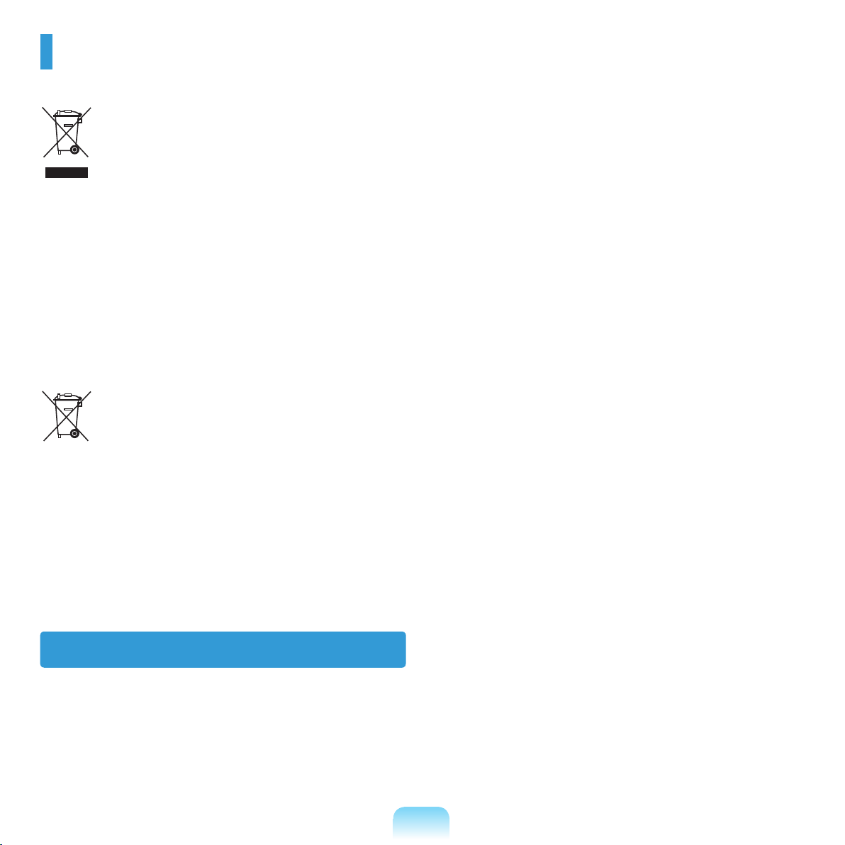
WEEE SYMBOL INFORMATION
Correct Disposal of This Product
(Waste Electrical & Electronic Equipment)
(Applicable in the European Union and other European countries with separate collection systems)
This marking on the product, accessories or literature indicates that the product and its electronic accessories (e.g.
charger, headset, USB cable) should not be disposed of with other household waste at the end of their working life.
To prevent possible harm to the environment or human health from uncontrolled waste disposal, please separate these
items from other types of waste and recycle them responsibly to promote the sustainable reuse of material resources.
Household users should contact either the retailer where they purchased this product, or their local government ofce, for
details of where and how they can take these items for environmentally safe recycling.
Business users should contact their supplier and check the terms and conditions of the purchase contract. This product
and its electronic accessories should not be mixed with other commercial wastes for disposal.
Correct disposal of batteries in this product
Pb
(Applicable in the European Union and other European countries with separate battery return systems.)
This marking on the battery, manual or packaging indicates that the batteries in this product should not be disposed of
with other household waste at the end of their working life. Where marked, the chemical symbols Hg, Cd or Pb indicate
that the battery contains mercury, cadmium or lead above the reference levels in EC Directive 2006/66. If batteries are
not properly disposed of, these substances can cause harm to human health or the environment.
To protect natural resources and to promote material re-use, please separate batteries from other types of waste and
recycle them through your local, free battery return system.
USA ONLY
This Perchlorate warning applies only to primary CR (Maganese Dioxide) Lithium coin cells in the product sold or
distributed ONLY in California USA.
“Perchlorate Material- special handling may apply, See www.dtsc.ca.gov/hazardouswaste/perchlorate.”
Contains Mercury, Dispose According to Local, State or Federal Laws.
For details see lamprecycle.org, eise.org, or call 1-800-Samsung.
40
Page 41
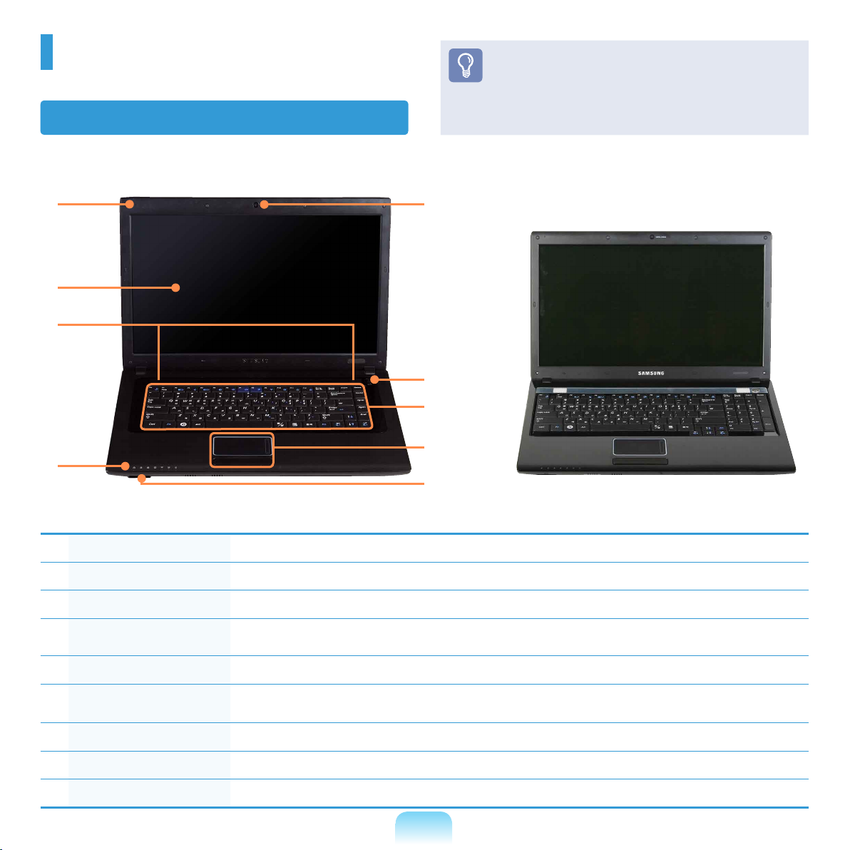
Overview
Front View
Before You Start!
Optional items may be changed or may not be
provided depending on the computer model.
The actual color and appearance of the computer
may differ from the pictures used in this guide.
1
2
3
4
Microphone You can use the built-in microphone.
1
LCD The screen images are displayed here.
2
Speaker A device used to generate sound.
3
Status Indicators
4
Shows the operating status of the computer.
The corresponding operating LED is lit when the corresponding function operates.
9
8
7
6
5
(For 16 inch models)
For 16 inch models, a different keyboard type is supplied.
Multi Card Slot A card slot that supports SD Card, SDHC, and MMC cards.
5
Touchpad/Touchpad
6
Buttons
Keyboard A device to enter data by pressing the keys.
7
Power Button Turns the computer on and off.
8
Camera Lens (Optional) Using this lens, you can take still pictures and record video.
9
The touchpad and touchpad buttons provide functions similar to the mouse ball and buttons.
41
Page 42
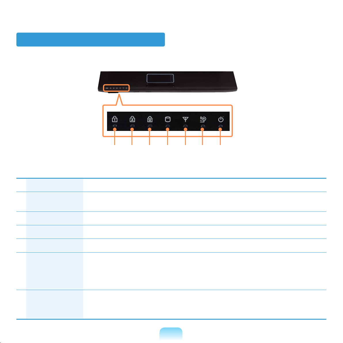
Status Indicators
1 2 3 4 5 6 7
Num Lock (Optional) This turns on when the Num Lock key is pressed and numeric keypad is activated.
1
Caps Lock This turns on when the Caps Lock key is pressed allowing capital letters to be typed without holding
2
the Shift button down.
Scroll Lock This turns on when the Scroll Lock key is pressed and screen scroll is locked.
3
HDD/ODD This turns on when the hard disk is or ODD being accessed.
4
Wireless LAN This turns on when the wireless LAN is operating.
5
Charge Status This shows the power source and the battery charge status.
6
Green: When the battery is fully charged or the battery is not installed.
Red: When the battery is being charged.
Off: When the computer is running on attery power without being connected to AC adapter.
Power This shows the computer operating status.
7
On:
When the computer is operating.
Blinks: When the computer is in Sleep mode.
42
Page 43
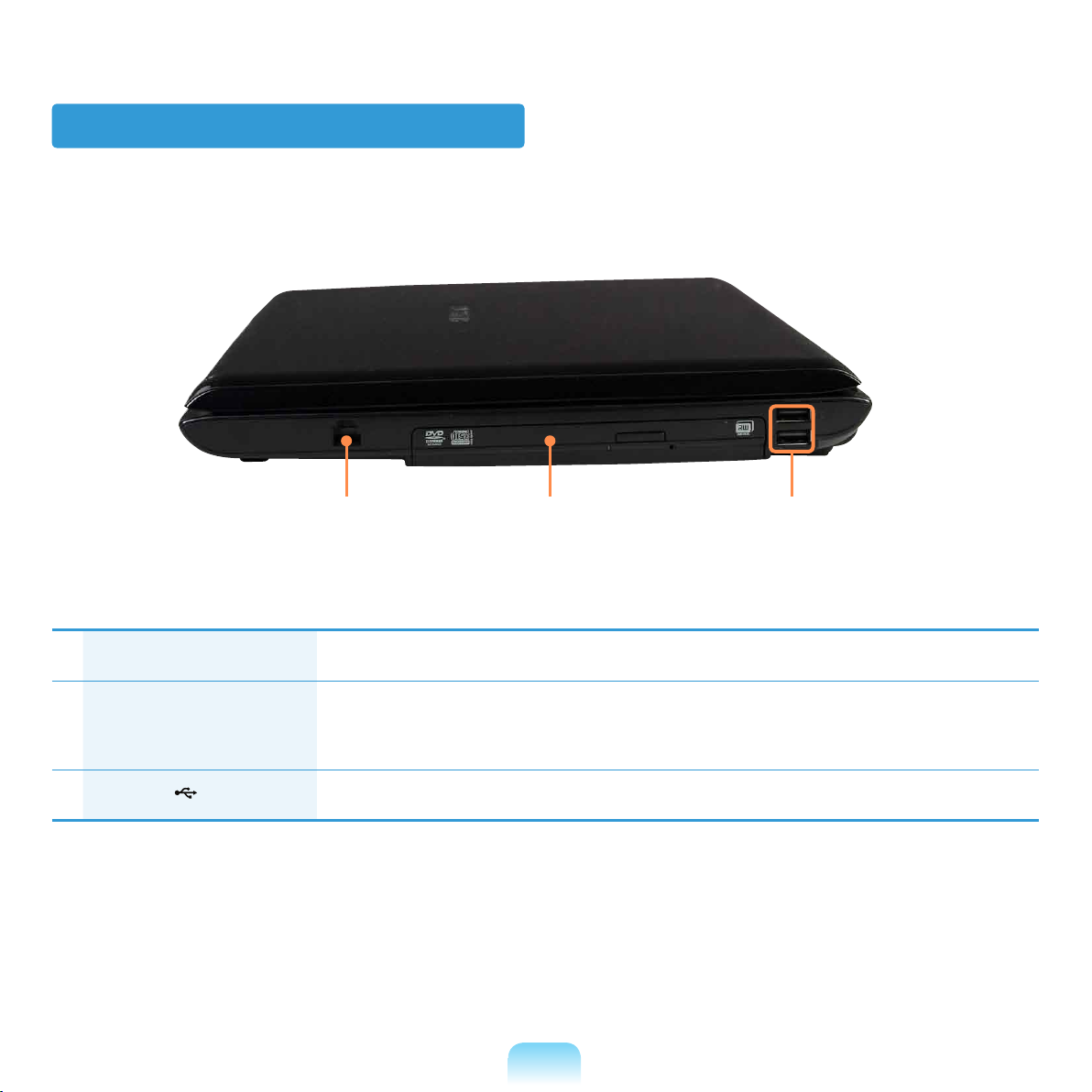
Right View
2 31
Modem Port (optional) A port to which a telephone cable is connected to in order to dial up to the Internet.
1
CD Drive(ODD) (Optional) Plays CD or DVD titles.
2
3
USB Port
Since an ODD(Optical Disk Drive) is optional, the installed drive depends on the computer
model.
You can connect USB devices to the USB port such as a keyboard/mouse, digital camera, etc.
43
Page 44
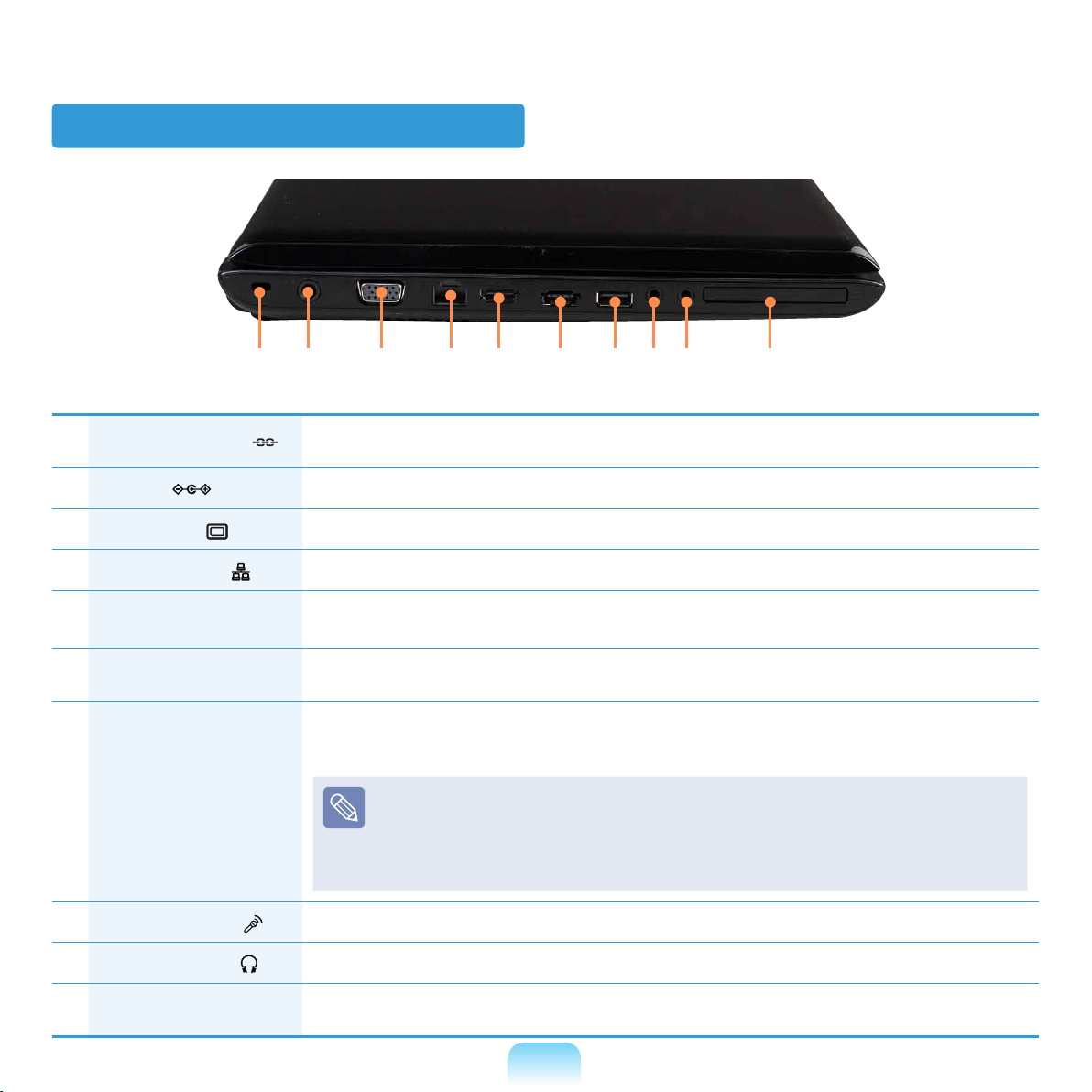
Left View
21 3 4 6 7 8 95 10
Security Lock Port
1
DC Jack
2
Monitor Port
3
Wired LAN Port
4
Digital Video/Audio Port
5
(HDMI) (Optional)
eSATA/USB Common
6
Port (Optional)
Chargeable USB
7
Port (Optional)
Microphone Jack
8
You can connect a Kensington lock to the Security Lock Port to prevent the computer from being
stolen.
A jack to connect the AC adapter that supplies power to the computer.
A port used to connect a monitor, TV or projector supporting a 15pin D-SUB interface.
Connect the Ethernet cable to this port.
You can connect an HDMI cable to this port.
Using this port, you can enjoy digital video and audio on the TV.
This port can be used to connect a USB or eSATA device.
You can connect USB devices to the USB port such as a keyboard/mouse, digital camera, etc.
(Chargeable USB: You can charge USB devices through the USB port even when the computer is
turned off.)
Charging a device through a Chargeable USB takes longer than using a regular
charger.
P
ress the F2 key when the Samsung logo appears in the booting sequence to enter the
BIOS Setup, select Advanced > USB Charge In Sleep Mode, and set it to Enable.
Then you can use the Chargeable USB Port feature even in sleep mode.
A jack used to connect the microphone.
Headphone Jack
9
ExpressCard Slot
10
(Optional)
A jack used to connect the headphones.
Install the Express card into this slot.
44
Page 45
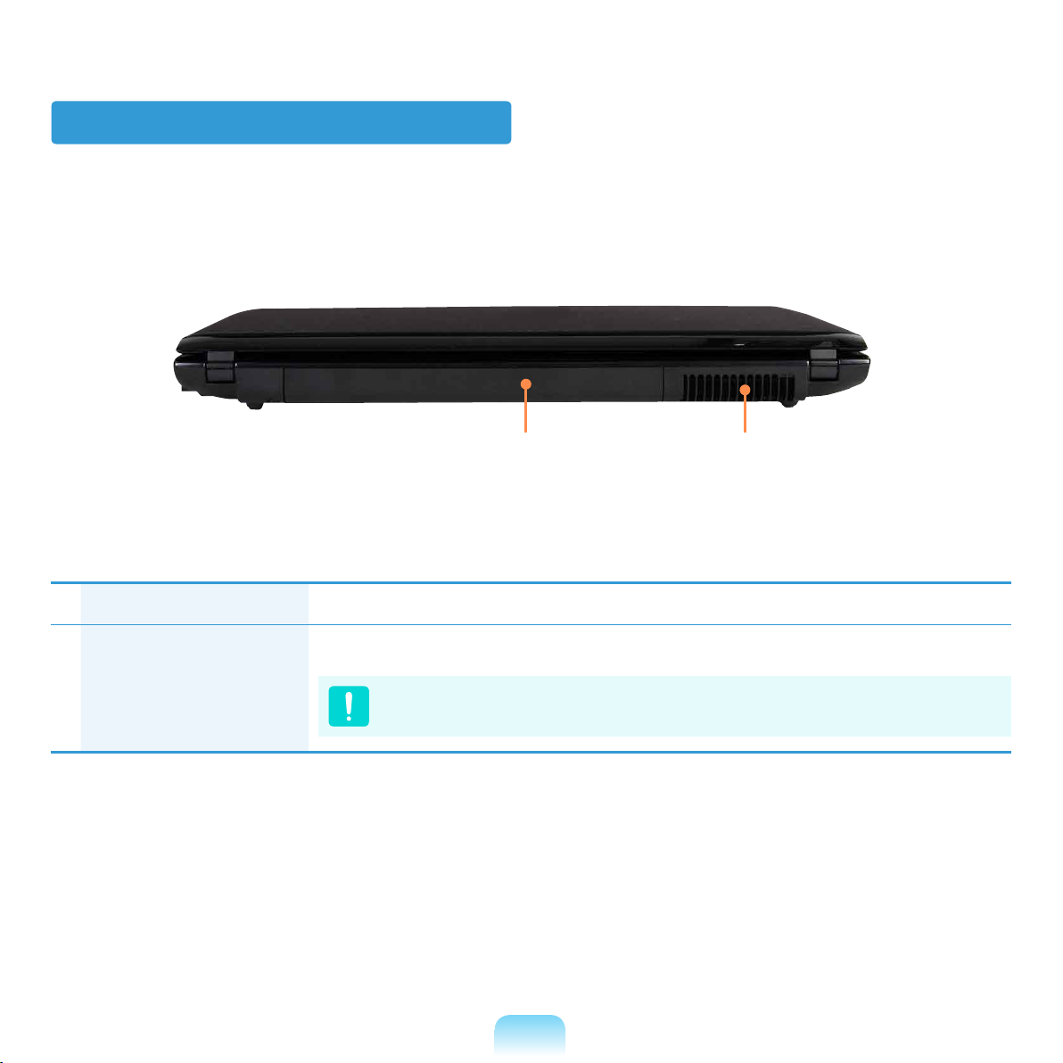
Back View
1 2
Battery This is a Lithium-Ion rechargeable battery that supplies power to the computer.
1
Fan Vents The internal heat of the computer is emitted through these holes.
2
If the vents are blocked the computer may overheat.
Avoid blocking the vents as this may be dangerous.
45
Page 46
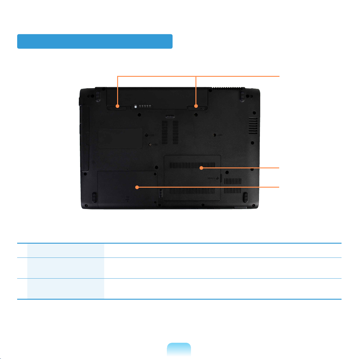
Bottom View
1
2
3
Battery Latches The latch used to remove or install the battery.
1
Memory Compartment
2
Cover
Hard Disk Drive
3
Compartment Cover
The main memory is installed inside the cover.
The hard disk drive is installed inside the cover.
46
Page 47
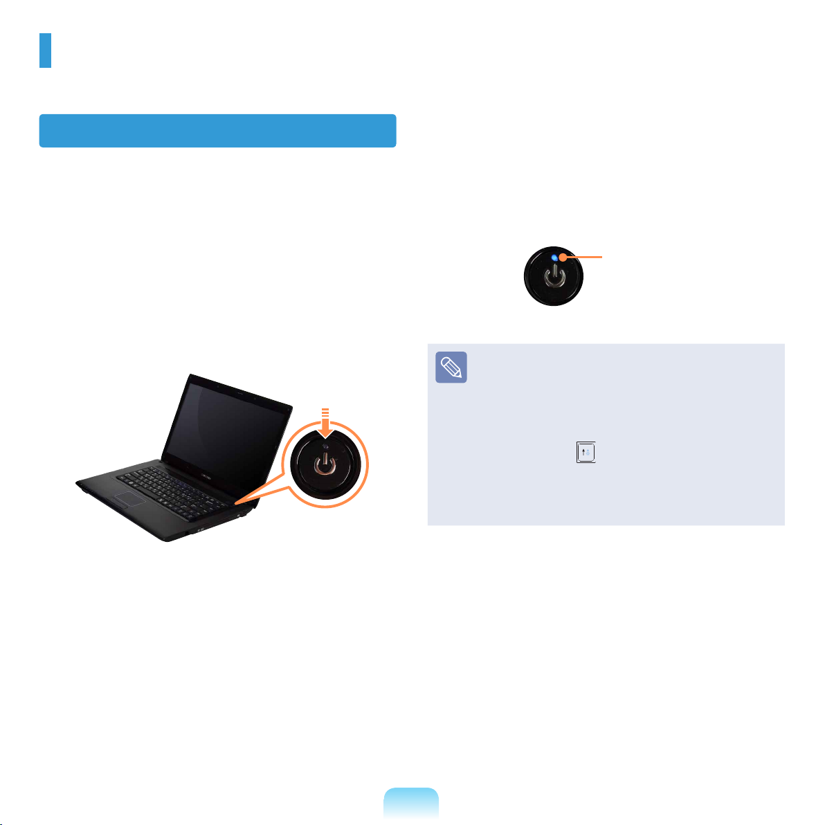
Turning the Computer On and Off
Turning the computer on
Install the battery and connect the AC adapter.
1
Lift the LCD panel up.
2
Press the Power button to turn the computer on.
3
Power button LED is lit while the computer is
4
turned on.
LED
If you press and release the Power button on the
computer when it is on, the computer enters Sleep
mode.
When running the computer on battery power, the
LCD brightness is dimmed automatically to save
battery power.
Press the Fn+ key to increase the LCD
brightness.
When turning the computer on for the rst time, the
Register Windows screen appears. You can use the
computer after registering your user information.
47
Page 48
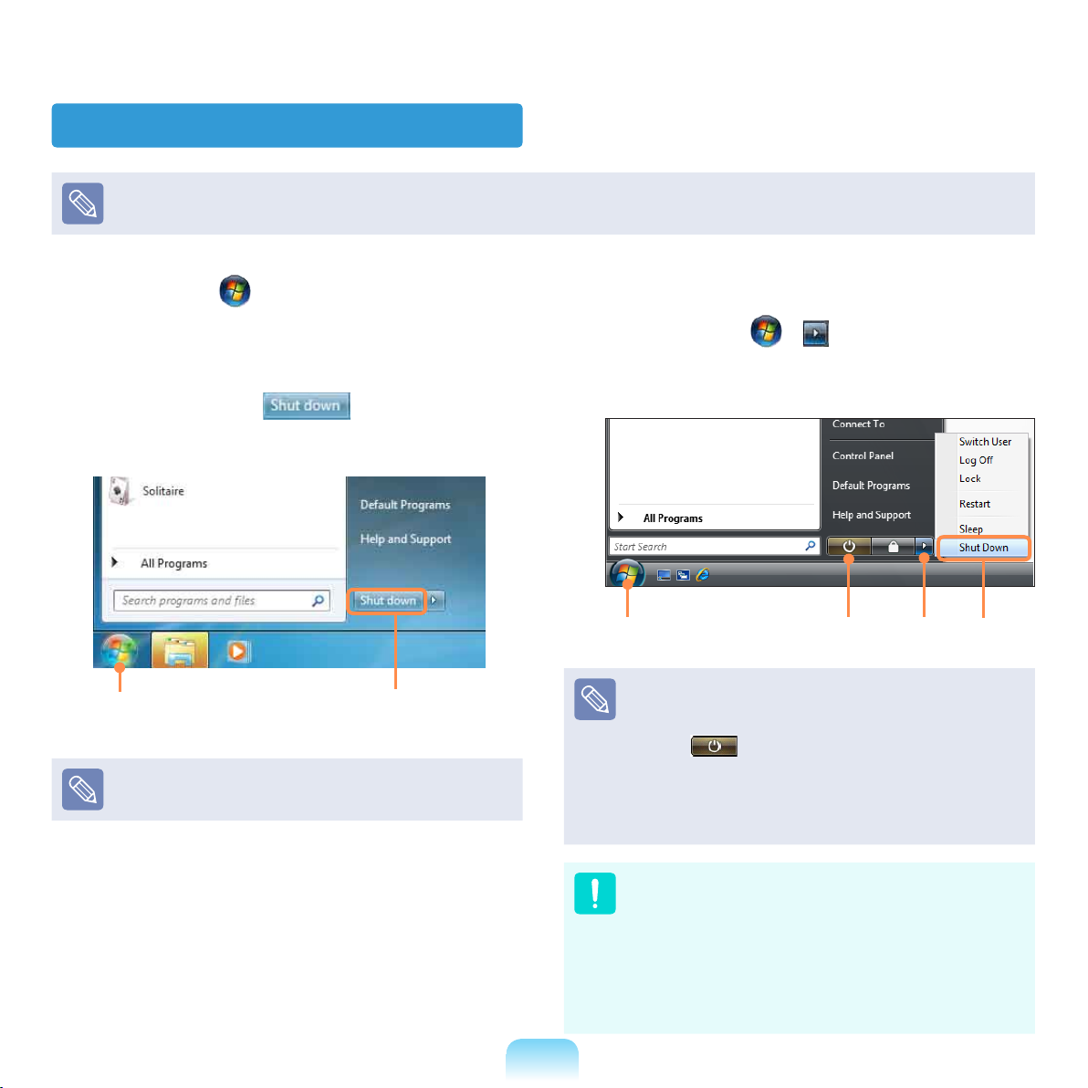
Turning the computer off
Since the procedures to turn the computer off may differ depending on the installed operating system, please turn the computer
off according to the procedures for the purchased operating system.
Click the Start button on the taskbar.
1
▶ For Windows 7
2
Click Shut Down to shut down the
computer.
1 2
Save all your data before clicking on Shut Down.
▶ For Windows Vista
Click on Start > and then click on Shut
Down as shown in the gure below to shut the
computer down.
1 2
Using the Power button in Windows Vista
For Windows Vista, the Power button is set to power
saving mode. Therefore, if you click Start > Power
button
mode.
To shut down the computer by clicking this icon, refer to
the descriptions for Setting up Start menu power button
of the Control Panel.
Power Button
, the computer enters power saving
3
48
If the system cannot be shut down due to a system
error, turn it off by pressing and holding the Power
Button for a minimum of 4 seconds.
Please note that turning the computer off by this
method may cause a system problem. Thereafter,
when turning the computer back on, the disk checking
program may launch to check for and correct any disk
errors.
Page 49

Chapter 2.
Using the computer
Keyboard 50
Touchpad 52
Basic Touchpad Functions 52
The Gesture Function of the Touchpad (Optional) 54
Touchpad On/Off Function 56
CD Drive (ODD, Optional) 57
Inserting and Ejecting a CD 57
Multi Card Slot (Optional) 59
ExpressCard Slot (Optional) 62
Connecting a monitor / TV 63
Connecting to the Monitor / TV 63
Viewing Through a Monitor / TV 65
Using Dual View 69
Adjusting the Volume 71
Wired Network 73
Wireless Network 76
Connecting to a Wireless LAN 76
Page 50
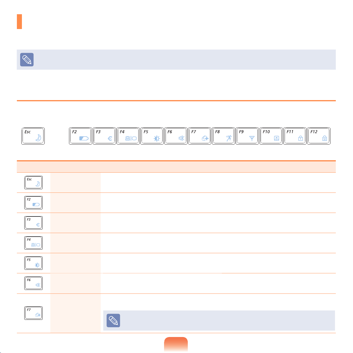
Keyboard
Shortcut key functions and procedures are discussed in the following sections.
The keyboard is supplied according to the corresponding country.
The keyboard may differ depending on your country. The following mainly describes the shortcut keys.
Shortcut Keys
You can use the following functions by pressing the keys below with the Fn key.
Fn+ Name Function
REST
(Sleep Mode)
Gauge
Euro
CRT/LCD
Backlight Turns the LCD backlight on or off.
Mute Mutes or cancels mute.
Samsung
Support Center
Switches to Sleep mode. To wake the computer up, press the Power button.
Shows the remaining battery charge.
You can only use this function when the Easy Display Manager program is installed.
Enters the Euro monetary unit symbol.
This key may not be provided depending on the keyboard type.
Switches the screen output to the LCD or external monitor when an external monitor (or TV) is
connected to the computer.
System diagnosis, recovery and Internet consultation program, Samsung Support Center, will be
launched. (Optional)
For some models, Samsung Magic Doctor is launched
50
Page 51
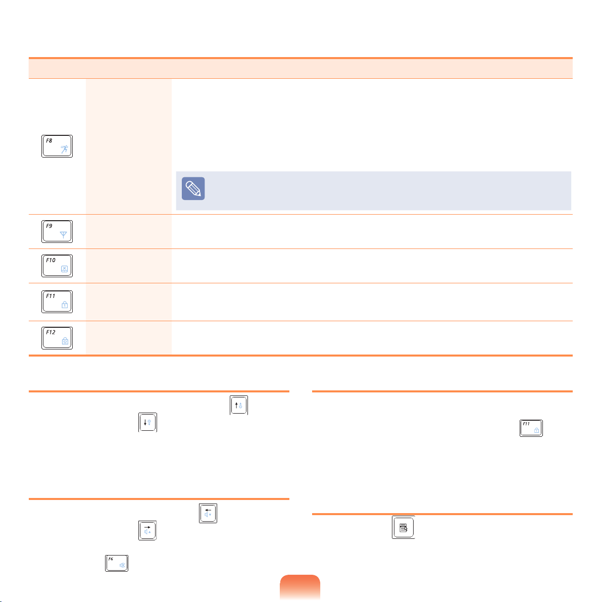
Fn+ Name Function
You can select operation mode when you need maximum system performance or low-noise/low
power consumption with one-click.
Silent: Low-noise and low power consumption mode
Normal: Normal Mode
Easy SpeedUp
Manager
Wireless LAN Turns the wireless LAN function on or off in models with wireless LAN capability.
Speed: Maximum performance mode. The system operates in its maximum performance,
and system resources are allocated to the currently active program with priority for maximum
performance.
If you don’t want fan noise turning ON and OFF in the Silent mode, select the Advanced
menu > Fan Silent Mode > Low in the BIOS Setup. The fan keeps turning ON and works
in Low noise mode.
Touchpad
Num Lock
(Optional)
Scroll Lock
Turns the Touchpad function on or off.
When using an external mouse only, you can turn the Touchpad off.
Turns the numeric keyboard on or off.
(For 16-inch models, once the Num Lock is on, the numeric keypad in the right side of the
keyboard is enabled.)
If you turn the Scroll Lock on, you can scroll the screen up or down without changing the cursor
location in some applications.
Screen Brightness Control
To adjust the LCD brightness press the Fn + key
combination or the Fn + key combination.
The changed screen brightness is displayed at the center
of the screen for a moment.
Volume Control
To control the volume, press the Fn + key
combination or the Fn + key combination.
You can mute the sound or cancel the mute function by
clicking the Fn + key combination.
Numeric Key
The numbers are printed in blue on the numeric keys.
If Num Lock is turned on by pressing the Fn +
key
combination, you can use the numeric keys to enter digits.
For 16-inch models, once the Num Lock is on, the Num
Lock light is lit and the numeric keypad is enabled.
Other Function Keys
Application Key
Performs the right-click mouse function (touchpad).
51
Page 52
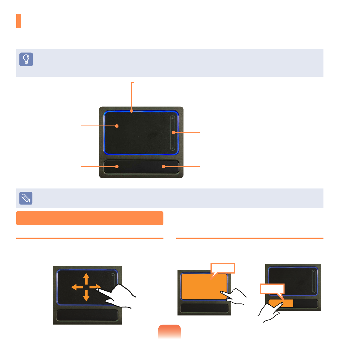
Touchpad
The touchpad provides the same function as a mouse and the left and right buttons of the touchpad plays the role of
the left and right buttons of a mouse.
Before You Start!
Use the Touchpad with your ngers. Using a sharp object may damage the Touchpad.
If you touch the Touchpad or press the Touchpad buttons while booting up, the Windows boot time may be extended.
Touchpad LED
Touchpad LED is lit while you touch the Touchpad.
The power is automatically turned off if there is no touchpad input for 30 seconds.
Touchpad
Use to move the cursor.
Scroll Area
Plays the role of the mouse
wheel. You can scroll up and
down using the Scroll Area.
Touchpad Left Button
You can select or run a
program using this button.
To deactivate the touchpad LED function or to keep the LED on, change the setting by selecting Advanced > Touch Pad LED in
the BIOS Setup.
Basic Touchpad Functions
Moving the cursor on the screen
Place your nger on the touchpad slightly and move your
nger. The mouse cursor will move accordingly. Move
your nger in the direction you wish to move the cursor.
Touchpad Right Button
Plays the role of the right
mouse button.
Click Function
Place your nger on the touchpad and tap your nger
once over an item you want. Alternatively, press the left
touchpad button once.
Tap
or
Click
52
Page 53
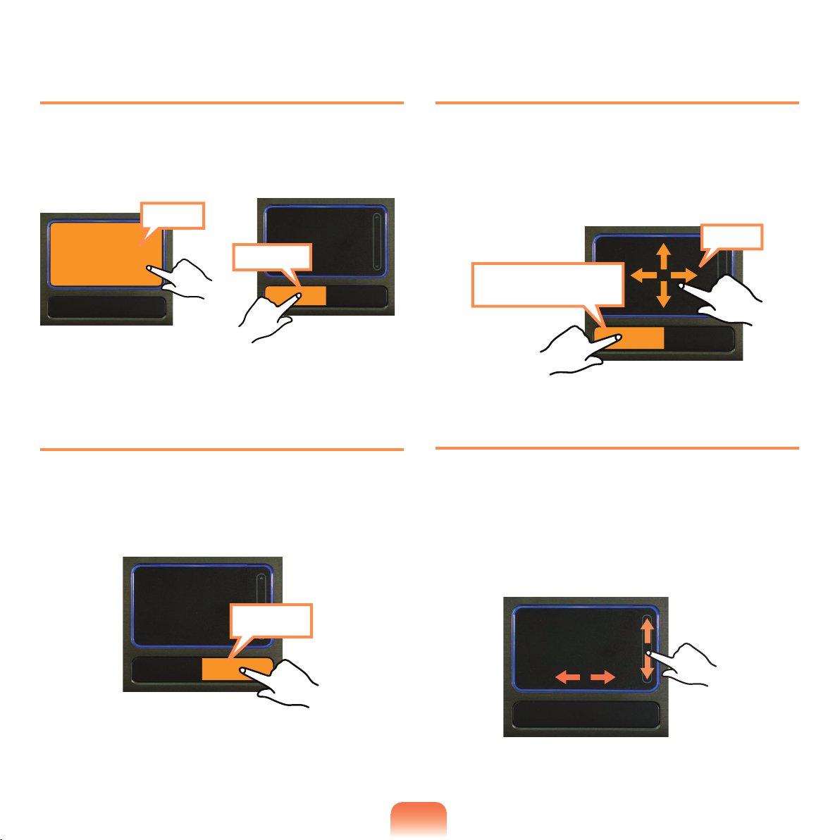
Double-Click Function
Drag Function
Put your nger on the touchpad and quickly tap twice with
your nger on an item you want.
Alternatively, press the left touchpad button twice quickly.
TapTap
ClickClick
or
Right Button Function
This corresponds to clicking the right mouse button.
Press the right touchpad button once. The corresponding
pop-up menu appears.
Dragging refers to moving an item to another place after
selecting it.
Press and hold down the left touchpad button over an
item you want to drag and move the item to the new
location.
Move
Holding down the left
touchpad button
Touchpad Scroll Function
The touchpad scroll area provides the mouse wheel
function (scroll function).
Place your nger on the touchpad’s right edge for vertical
scrolling or the bottom edge for horizontal scrolling and
then move your nger along the edge to scroll the screen
vertically or horizontally.
Click
53
Page 54

The Gesture Function of the Touchpad (Optional)
The Touchpad Gesture function may not be provided and the version of the function may differ depending on the model. Some
usage procedures may differ depending on the version.
For detailed usage procedures, refer to the description in the Touchpad Settings window. In addition, if you click the Show
Video button of each item, you can refer to the video descriptions.
The images in this document may differ from the actual screen images and a different Touchpad may be provided depending
on the model. In addition, since the pictures used in this document are pictures of a representative model, they may differ from
the actual appearance of your computer.
Since these descriptions are written on the basis of the latest operating system, Windows 7, some of the content and the
gures of the descriptions may differ depending on the operating system. Since the procedures for other Windows operating
systems are similar, use the computer referring to these descriptions.
The path may differ depending on the operating system.
Using the Touchpad, you can use the following additional Gesture functions.
Scroll function using two ngers
Zoom functions using two ngers
Rotation function using two ngers.
Move function using three ngers
Slide Show function using three ngers
Conguring the Gesture Function
If the Gesture function is not activated, you can activate it
according to the following procedures.
Click the Start > Control Panel > Hardware and
1
Sound > Mouse > Device Settings tab > Settings
button.
54
The Touchpad Settings window appears. Click over
2
the corresponding item to select the item in the
Select an item and click OK.
To cancel the Gesture function, unselect the
corresponding item in the Touchpad Settings window
and click OK.
Page 55
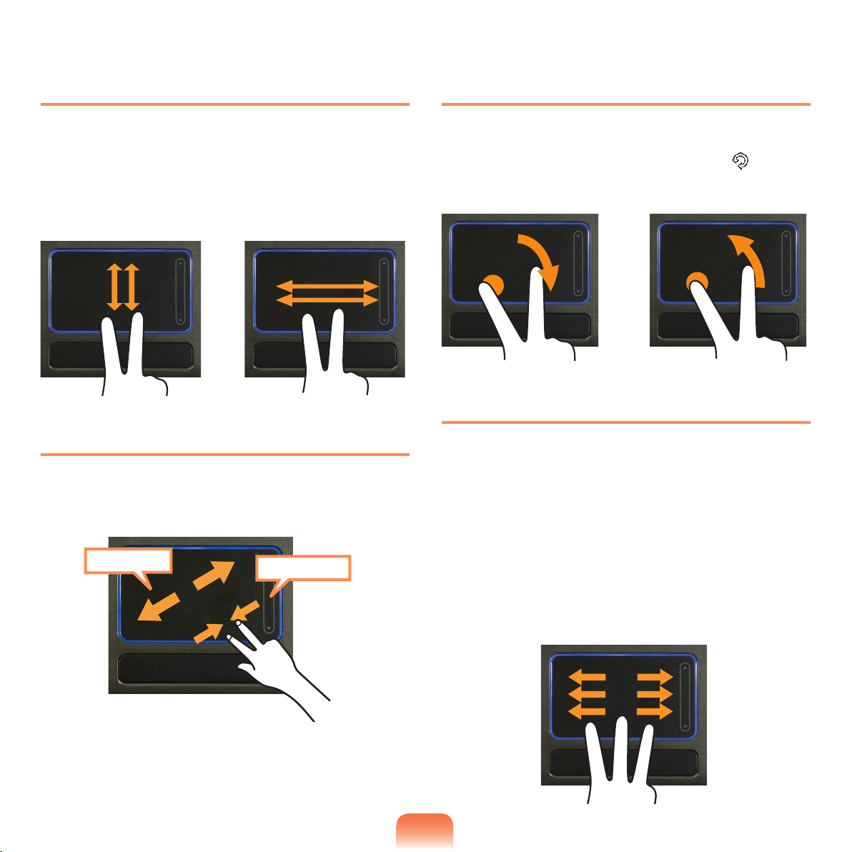
The Scroll Function
Rotation Function
This function is the same as the scroll area of the
Touchpad.
If you place two ngers over the Touchpad and move
them up, down, left or right, the screen is scrolled up,
down, left or right.
or
Zoom Functions
If you place two ngers over the Touchpad together or
apart, the current image or text is zoomed in or out.
Zoom-in
or
Zoom-out
If you place two ngers over the Touchpad, and keep one
nger in place and turn the other nger in the left or right
direction, the mouse pointer changes into the icon and
the current photo or image is rotated.
or
Move Function
When watching a photo or surng the Internet, you can
move to the previous or next photo or Internet page
without using the mouse or buttons.
Place three ngers over the Touchpad and slightly touch
the surface of the Touchpad with them in the left or right
direction to move to the previous or next photo or Internet
page.
For example, if you touch the Touchpad in the left
direction using three ngers while looking at a website,
the previous page is displayed.
55
Page 56
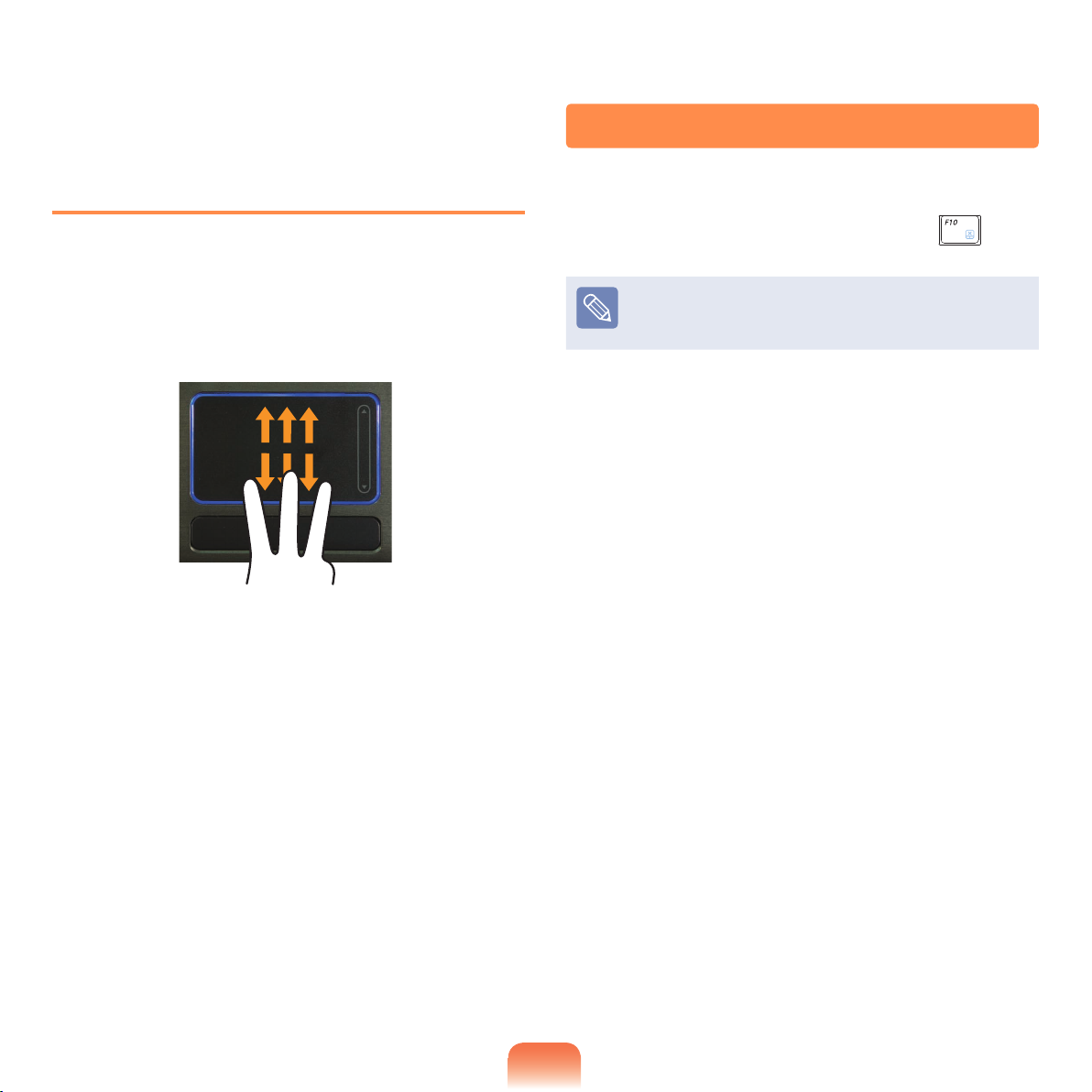
Touchpad On/Off Function
Slide Show Function
When viewing a photo, if you place three ngers onto
the Touchpad and slide them upwards, the Slide Show
begins.
To nish the Slide Show, place three ngers onto the
Touchpad and slide them downwards.
If you want to use the mouse only without using the
touchpad, you can turn the touchpad off.
To lock the touchpad function, press the Fn +
You can set the touchpad and touchpad button settings
in the tabs that appear when clicking Start > Control
Panel > Hardware and Sound > Mouse.
keys.
56
Page 57
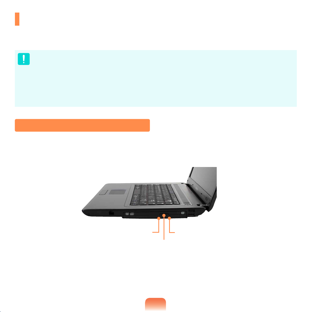
CD Drive (ODD, Optional)
An optical disk drive is optional and may differ depending on your computer model. For detailed specications, refer
to the catalogue.
Do not insert a cracked or scratched CD.
Otherwise, the CD may break and damage the optical disk drive when the CD rotates at a high speed.
When you clean a CD or DVD title, wipe with a soft cloth from inside to outside.
DVD Super Multi LS (LightScribe) are only available for some models.
Insert a Mini CD into the center of the CD drive.
The gures used for the description are of a representative model. Therefore the gures may differ from the real ones.
Using a CD that is not in the shape of a circle is not recommended.
Blu-Ray drive is provided for some models only.
Inserting and Ejecting a CD
Click the Eject button of the optical disk drive at the side of the computer.
1
Status Indicator
Emergency Hole
Eject Button
57
Page 58
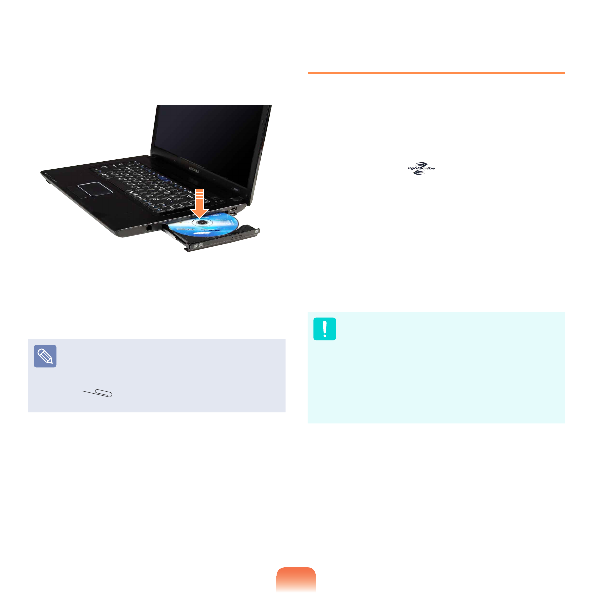
When the CD tray opens, insert a CD or DVD and
2
push the tray in until it clicks.
Push the CD tray inward until it clicks.
3
The CD drive status indicator is turned on.
A CD drive’s reading and writing speed may differ
depending on the condition and type of the media.
To eject a CD when the CD drive does not work or
the computer is off, place the end of a paper clip
(
is ejected.
) into the Emergency Hole until the CD tray
Using LightScribe (Optional)
LightScribe is a feature that allows you to print letters or
images onto the surface of a CD/DVD when recording
data.
LightScribe’s features are provided for DVD Super Multi
drives (ODDs) that support LightScribe.
If the LightScribe logo
CD drive (ODDs), it means the LightScribe feature is
supported.
For models supplied with Cyberlink DVD Suite, you can
print a label using the LabelPrint function of Cyberlink
DVD Suite.
For detailed procedures on using this function, refer to the
help section of the program.
Even if the Disk label print program is installed on
your computer or the LightScribe Control Panel
program icon is in the system tray of the Taskbar,
you cannot use the LightScribe function, if your
CD-ROM drive (ODD) does not support this function.
If the LightScribe menu is not shown in CyberLink
Label Print even for a model that supports
LightScribe, please go to http://www.lightscribe.com/
and download the latest version of LightScribe.
is on the surface of the
58
Page 59
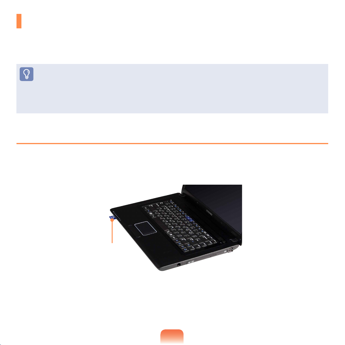
Multi Card Slot (Optional)
Using the multi card slot, you can read and write data to a SD card, SDHC card, MMC card.
You can use a card as a removable disk and conveniently exchange data with digital devices such as a digital
camera, digital camcorder, MP3, etc..
Before You Start!
You have to additionally purchase a multi card with the necessary capacity depending on your requirements.
You can use a multi card just like any data storage device. A copyright protection function is not supported.
Since you can lose a card when moving the computer, keep the card separately.
Supported Cards : SD Card, SDHC card, MMC
The gures used for the description are of a representative model. Therefore the gures may differ from the real ones.
To Insert and Use a Memory Card
Insert a card into the slot according to the directions printed on the slot.
1
Example) SD Card
59
Page 60
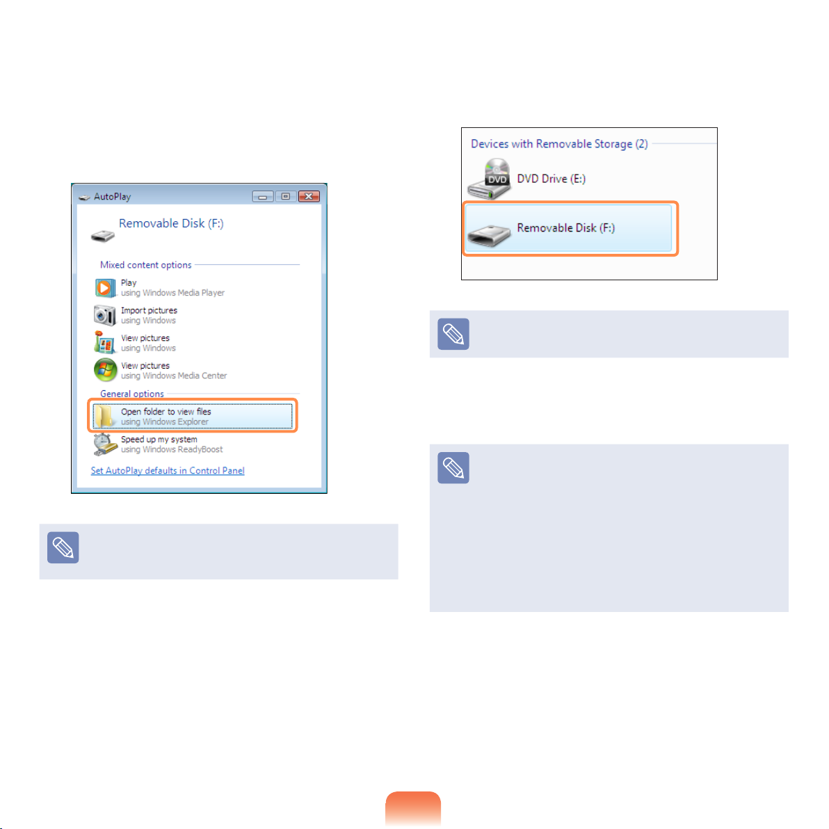
The card drive appears. Click Open folder and
2
view les.
If the window does not appear, click Start >
Computer.
If a window asking to scan and change appears, click
Continue Without Scanning. This will proceed to Step
2 above.
You can save, move and delete data by double-
3
clicking the corresponding drive.
The device name of the card drive may differ depending
on your computer model.
You can only use the card after formatting it.
Using a Mini SD and RS-MMC
Since the above cards are too small, you cannot insert
the cards into the slot directly.
Insert the card into the dedicated adapter (available
from most electronic retailers) and then insert the
adapter into the multi card slot.
However, depending on the adapter’s body material,
some RS-MMC cards may not be recognized properly.
Samsung recommend that you check the card is
recognized correctly prior to purchasing.
60
Page 61

To remove a memory card
Take hold of the end of the card and remove the card.
To format a memory card
When using the memory card for the rst time, you must
format the card before using it.
Formatting a card deletes all data saved on the card.
If the card includes data, backup the data before
formatting it.
Click Start > Computer.
1
Right-click over a card drive with the touchpad and
2
select Format.
To use a card to exchange data with a digital device
such as a digital camera, formatting the data using
the digital device is recommended.
When you try to use a card, which is formatted in the
computer, in another digital device, you may have to
format the card again in the device.
You cannot format, write or delete data from a SD, or
SDHC card with a write protection tab when it is in
the Lock position.
Inserting and removing a memory card repeatedly
may damage the memory card.
Click Start to the formatting.
3
61
Page 62
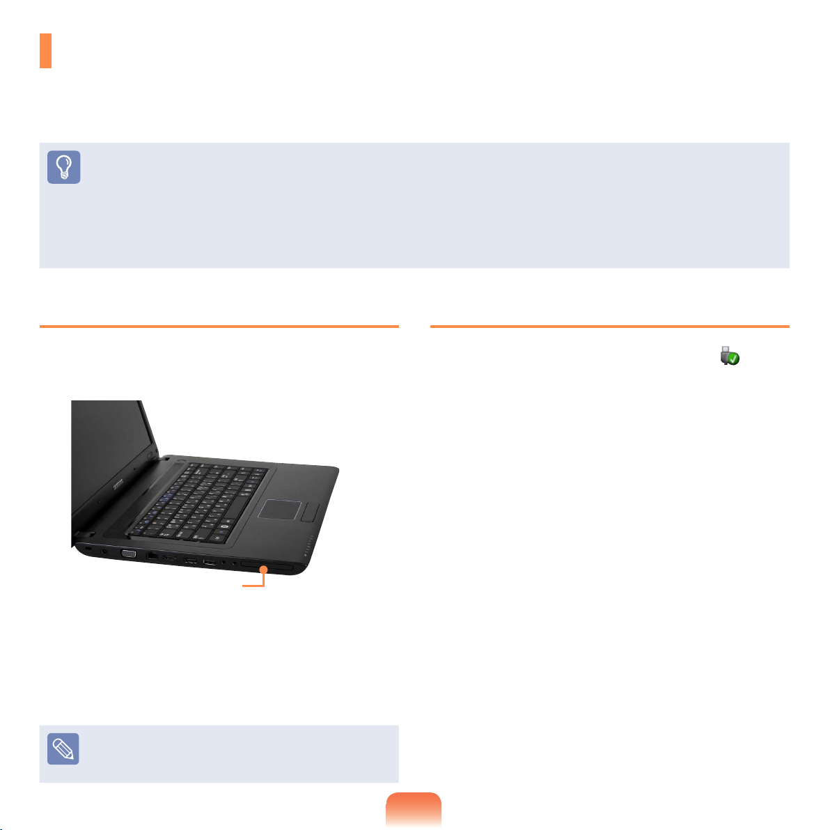
ExpressCard Slot (Optional)
You can use Express cards using this slot.
The ExpressCard slot can be regarded as the next generation PCMCIA card specication and supports LAN, TV
Tuner and Sound cards. This computer’s slot supports the Express Card/34 specication.
Before You Start!
Remove the dummy card installed to protect the slot rst. (Optional)
Lightly push the dummy card of the slot. The dummy card pops up. Eject the dummy card.
This slot is a ExpressCard slot. You cannot connect a PCMCIA card here.
Since these descriptions are written on the basis of the latest operating system, Windows 7, some of the content and the
gures of the descriptions may differ depending on the operating system. Since the procedures for other Windows operating
systems are similar, use the computer referring to these descriptions.
To insert a card
Insert a card into the slot on the side of the
1
computer.
ExpressCard Slot
If you insert a card into the slot, Windows recognizes
2
the card automatically or a message telling you to
install a driver appears.
If the card is not automatically recognized, install the
device driver supplied with the card.
To remove a card
Click the Safely Remove Hardware icon on the
1
task bar.
Click Remove ExpressCard.
2
You can remove the express card when the Safely
3
Remove Hardware message appears.
Push the card in the slot lightly.
4
Then the card pops up.
Eject the card.
5
If a window asking whether you want to scan and
change appears, click on Continue Without Scan.
This will proceed to Step 2 above.
62
Page 63
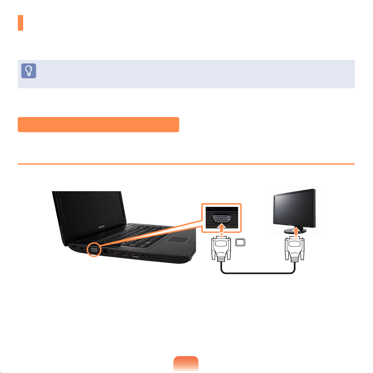
Connecting a monitor / TV
Using an external display device is useful when you are giving a presentation or watching a video or movie through
your monitor.
Before You Start!
You have to buy a connection cable additionally.
Due to restrictions of the operating system the DualView function is not supported for Windows 7 Starter.
Connecting to the Monitor / TV
Connecting to the Monitor port
Connect the computer to the RGB port of the monitor or TV using a monitor cable (15-pin).
63
Page 64
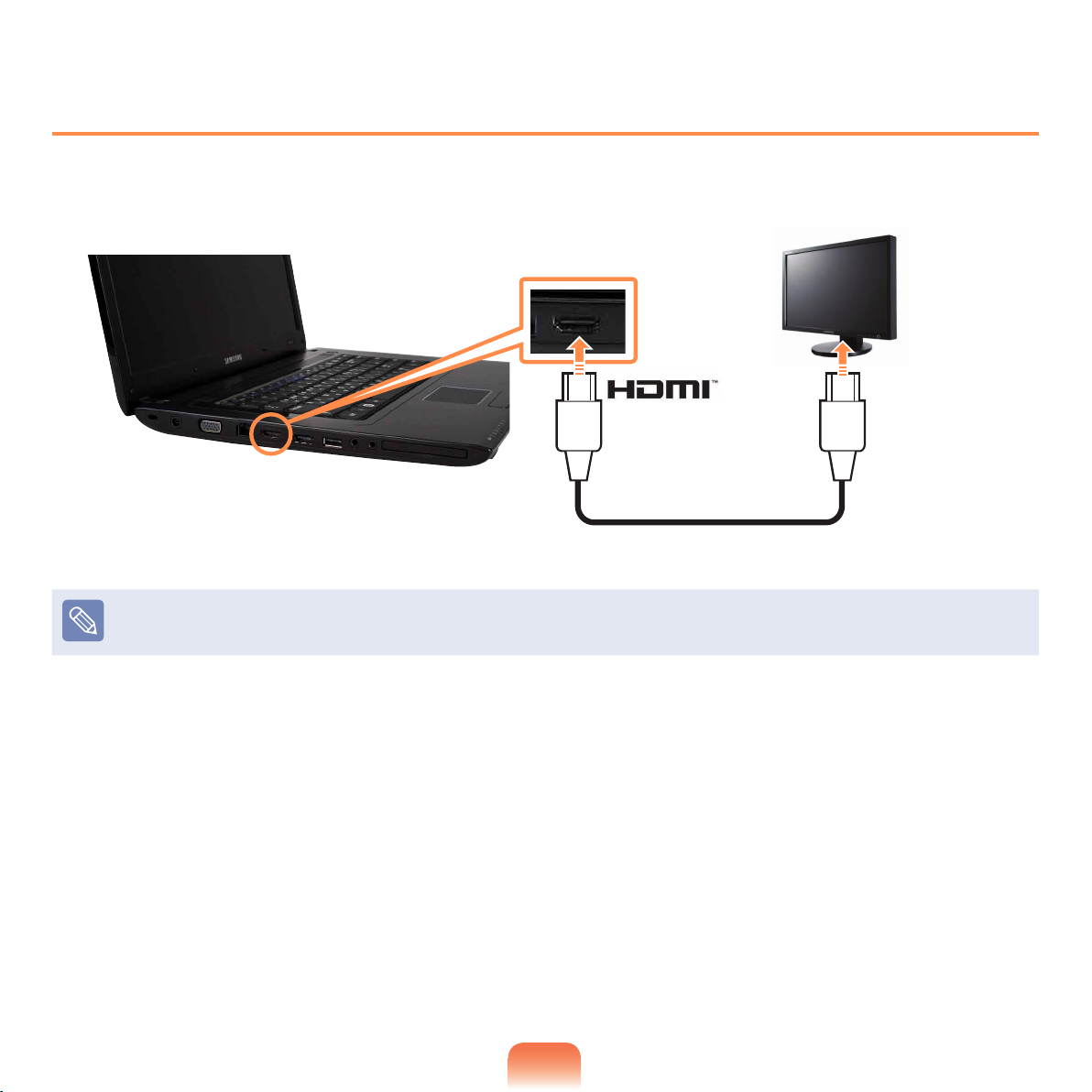
Connecting to the HDMI port (Optional)
Connect the computer to the HDMI port of the monitor or TV using a HDMI cable.
When connecting the computer to a TV, switch the external input mode of the TV to ‘HDMI’.
When a TV provides more than one HDMI port, connect the computer to the “DVI IN” port.
64
Page 65
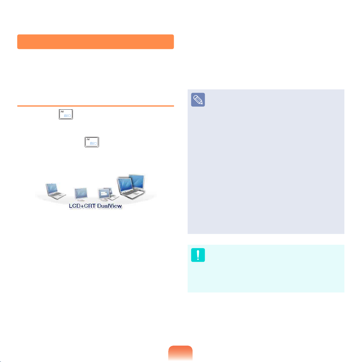
Viewing Through a Monitor / TV
You can switch the display device using the shortcut key.
Switching the Display Device using the
Shortcut Key
Press the Fn + key combination once. Then the
Easy Display Manager screen appears in which you can
select a display device.
Whenever you press the
Fn key, the selected option is changed.
Example) Selecting LCD+CRT Dual View
key while holding down the
LCD: Notebook Screen
CRT: External Monitor Screen
HDMI : TV Screen or Monitor (when it is connected
via the HDMI port).
LCD+CRT Clone : Notebook+ External Monitor
Screen
LCD+CRT DualView: Notebook+ External Monitor
Screen in Dual View
LCD+HDMI Clone: Notebook+ TV(or Monitor)
Screen
LCD+HDMI DualView: Notebook+ TV(or Monitor)
Screen Dualview
What is Dual View?
Dual View is a function that enables you to view
a computer screen over two display devices. It is
convenient when you need a wide screen.
Due to restrictions of the operating system the
DualView function is not supported for Windows 7
Starter.
The TV screen is only supported for models that
support the TV output port (HDMI).
Simultaneous output to all 3 (LCD + CRT + HDMI) is
not supported.
External Monitor / TV is not supported in the DOS
Command Prompt window.
65
Page 66
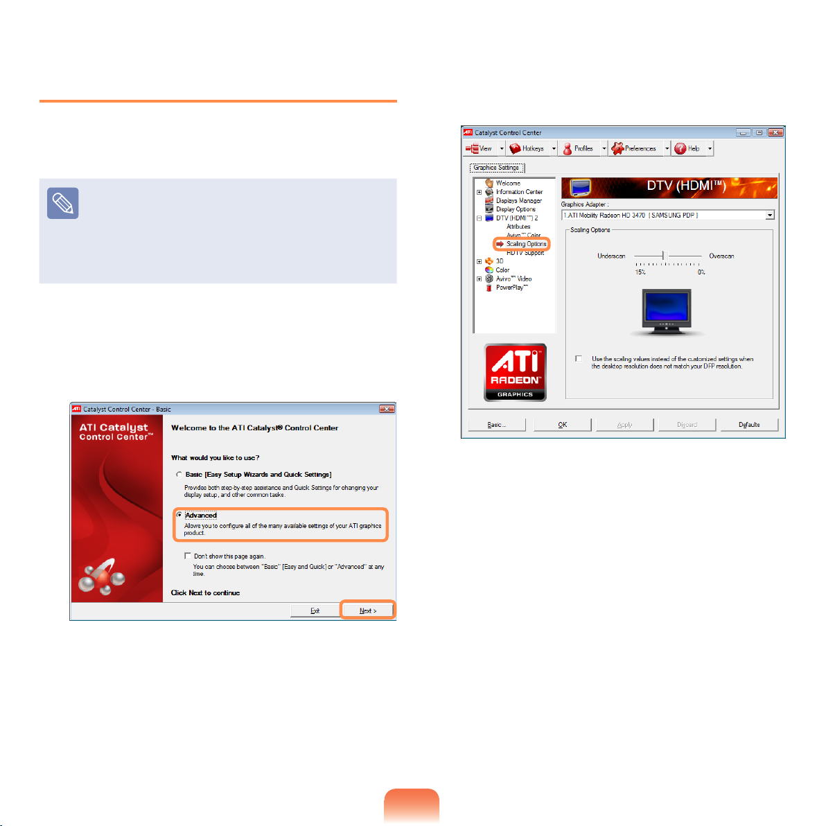
Setting up HDMI TV video (Optional)
If the Desktop screen displayed on the TV does not t to
the TV screen, congure it as follows depending on the
graphics card.
You can view the graphics card type by selecting
Device Manager > Display adapters and then
clicking the + symbol.
The screen images and terms may differ from actual
product depending on the computer model and driver
version.
For ATI graphics cards
Right-click over the Desktop and select ATI Catalyst
1
Control Center > Advanced and click Next.
In the Graphics Setting window, select the
2
DTV(HDMI™)2 > Scaling Options.
Fit the Desktop to the TV screen by sliding a resize
3
bar and click OK.
66
Page 67
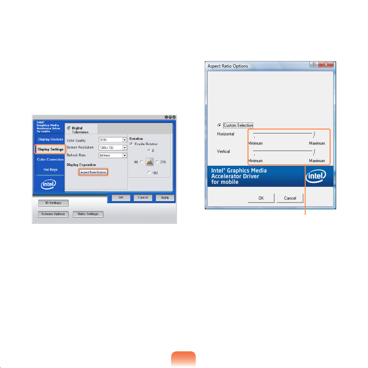
For Intel graphics cards
Right-click over the Desktop and select Graphics
1
Properties.
Click Display Settings and click the Aspect Ratio
2
Options.
Fit the Desktop to the TV screen by sliding the
3
Horizontal and Vertical Resize Bars and click OK.
67
Resize Bars
Page 68
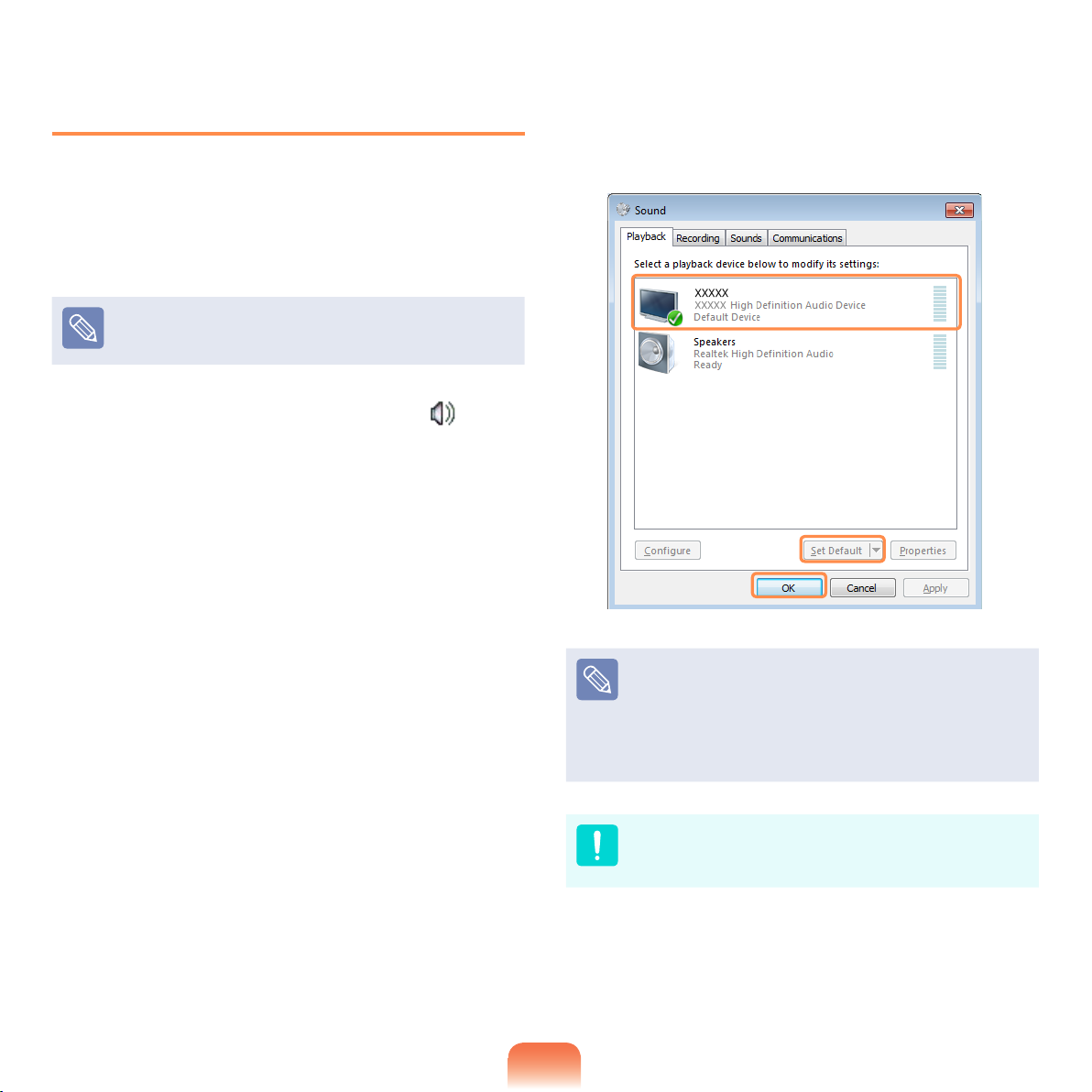
Setting up HDMI TV audio (Optional)
You can congure the sound of the computer to be played
through the HDMI TV. You have to congure the sound
device in the Control Panel whenever you connect the
HDMI TV in order to hear sound from the computer on the
TV.
The screen images and terms may differ from actual
product depending on the computer model.
Right-click over the Volume Control icon in the
1
notication area at the bottom right of the Desktop
and select Playback Devices.
(Alternatively, click the Control Panel > Hardware
and Sound > Sound.)
If the default Playback Device is set to Speakers,
2
change it to Digital Output Device(HDMI) (or HDMI
Device), click Set Default and then click OK.
68
HDMI Output Device may not appear on the playback
device list depending on the computer model.
In this case, turn on the TV, connect the TV to the
computer using a HDMI cable and then switch to HDMI
or LCD+HDMI Clone or LCD+HDMI DualView mode
using the Shortcut Key(Fn + F4).
To listen to sound on the computer after disconnecting
the HDMI TV, you have to set the Playback Device to
Speakers.
Page 69
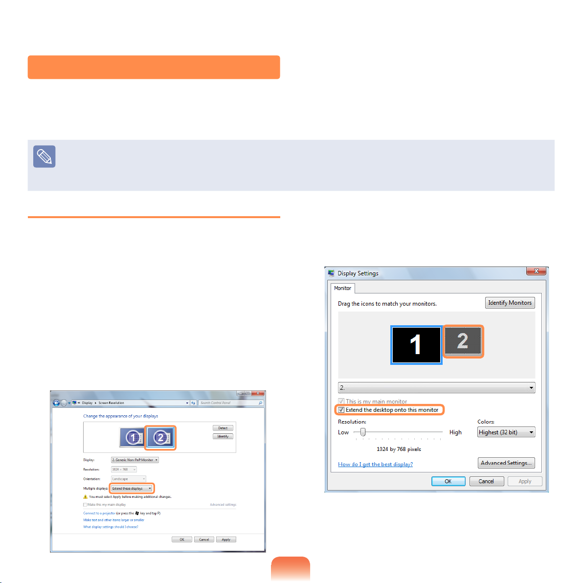
Using Dual View
Dual View enables users to expand their computer screen over two display devices.
Dual View is convenient when a wide operating space is needed. In addition, since Dual View operates as if there are 2
graphic cards present even when there is only one, you can set the resolution and color for each display device.
Since these descriptions are written on the basis of the latest operating system, Windows 7, some of the content and the
gures of the descriptions may differ depending on the operating system. Since the procedures for other Windows operating
systems are similar, use the computer referring to these descriptions.
Due to restrictions of the operating system the DualView function is not supported for Windows 7 Starter.
Selecting Dual View
Check if the external display device is properly connected
and follow the instructions below.
Click the Start > Control Panel > Appearance and
1
Personalization > Adjust screen resolution.
▶ For Windows 7
2
Click the monitor number 2 icon and select
Extend these displays in the Multiple displays
item. Click the Apply button and then the OK
button.
▶ For Windows Vista
Click on the number 2 monitor icon and select
Extend the desktop onto this monitor. Click
Apply and then click the OK button.
69
Page 70
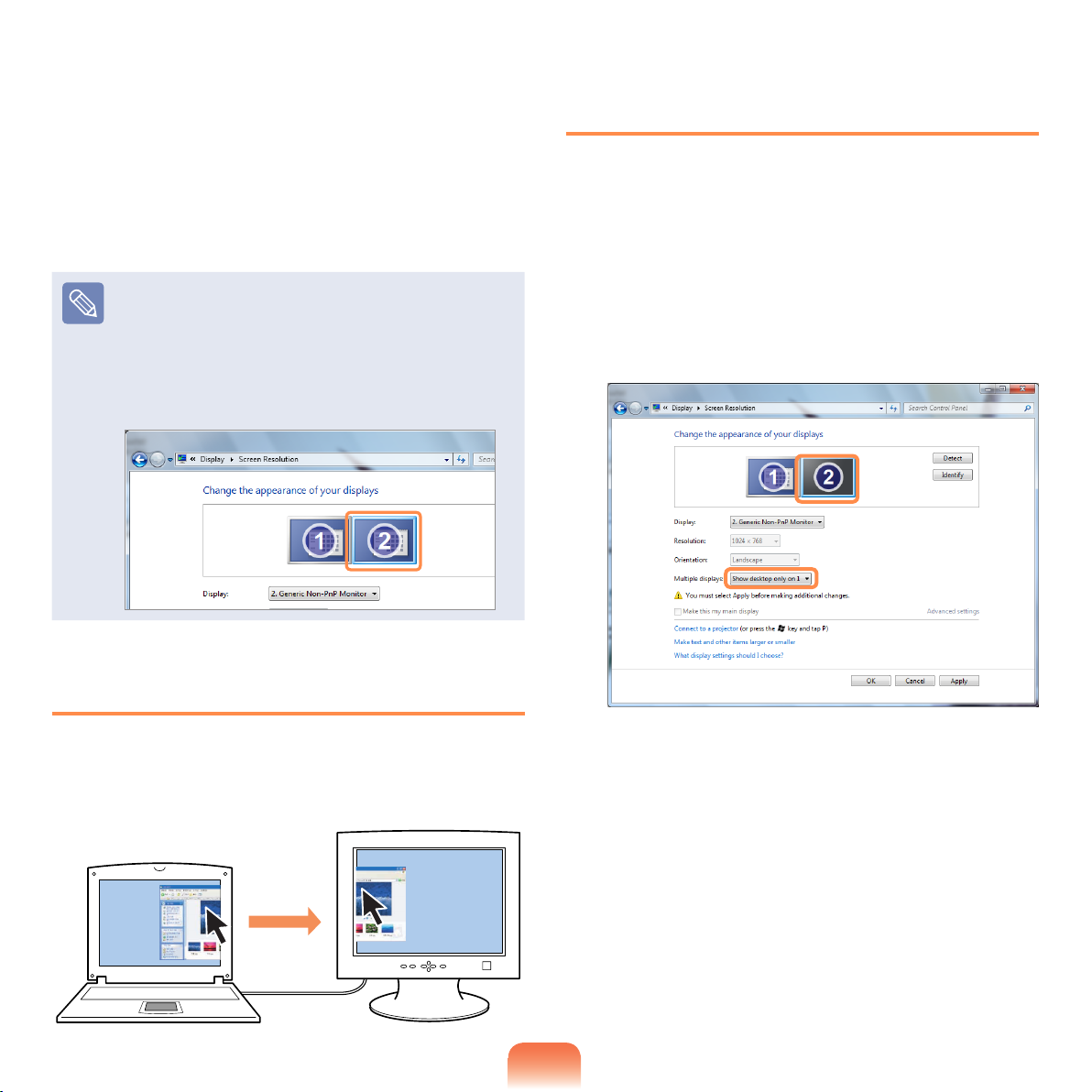
When notebook LCD is set as the main device, the
()
3
1 digit is displayed over it and the 2 digit is displayed
over the auxiliary display device. Now you can
expand the Desktop screen over 2 display devices.
When using Dual View, it is recommended setting
the LCD as the main device (number 1).
Adjusting the resolution of the auxiliary display
device (Monitor Number 2)
If the resolution of the auxiliary display device is
output, you can adjust the resolution and color quality
by clicking Start > Control Panel > Appearance
and Personalization > Adjust screen resolution >
Monitor Number 2.
Canceling Dual View
Click the Start > Control Panel > Appearance and
1
Personalization > Adjust screen resolution.
▶ For Windows 7
2
Click the monitor number 2 icon and select Show
Desktop on 1 only in the Multiple displays
item. Click the Apply button and then the OK
button.
Using Window in Dual View
Click on the window title bar of the main LCD (monitor
number 1) and drag it into the auxiliary display device
(monitor number 2) to move the window.
▶ For Windows Vista
Click on the Monitor Number 2 icon, unselect
Extend the desktop onto this monitor, and
then click Apply.
70
Page 71
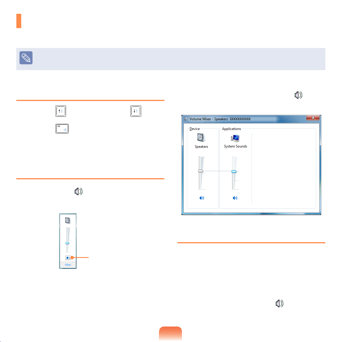
Adjusting the Volume
You can adjust the volume using the keyboard and the volume control program.
Since these descriptions are written on the basis of the latest operating system, Windows 7, some of the content and the gures
of the descriptions may differ depending on the operating system. Since the procedures for other Windows operating systems are
similar, use the computer referring to these descriptions.
Adjusting the Volume using the Keyboard
Press the Fn + key combination or Fn + key
combination to adjust the volume.
Press the Fn +
on or off.
key combination to turn the volume
Adjusting the Volume using the Volume
Adjustment Program
Click the Volume icon on the taskbar and slide the
volume control bar to adjust the volume.
Mute
Alternatively, right-click over the Volume icon and
select Open Volume Mixer to adjust the volume.
Using the Sound Recorder
The procedures to record sound using the Windows
Recorder are described below.
71
Connect a microphone to the microphone jack.
1
You can also use the internal MIC.
Right-click over the Volume icon on the taskbar
2
and select Recording Device.
Page 72
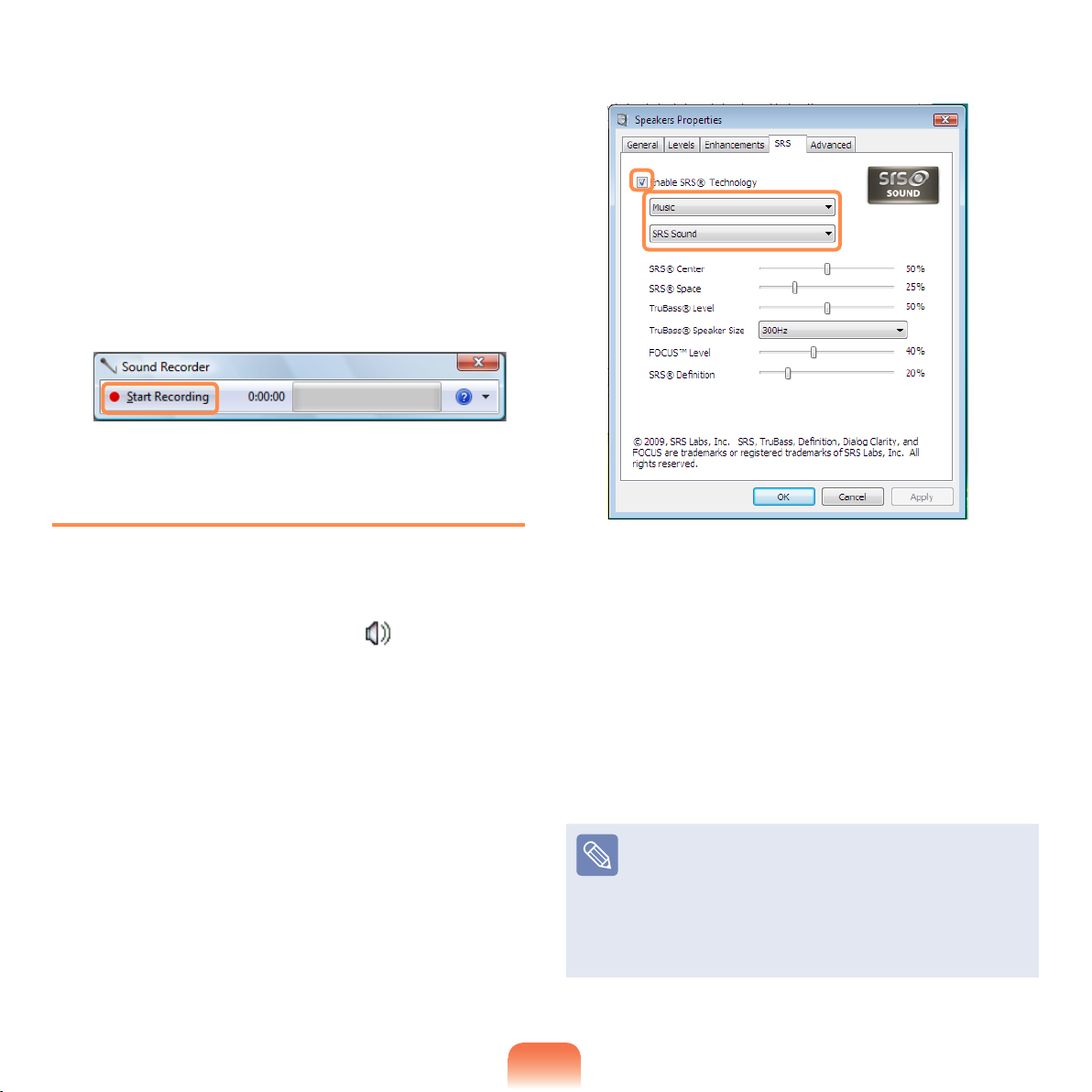
Check if the microphone is set as the default
3
recording device.
If this is the case, it is already set as the default
device. If not, right-click over the microphone and
select Set default.
Click Start > All Programs > Accessories >
4
Sound Recorder and click Start recording to start
a recording.
Using SRS
The SRS function enables you to experience more
stereophonic sound using stereo speakers.
x
z
Music: Select to listen to music.
WOW HD technology has been used.
Right-click over the Volume icon in the Taskbar
1
and select Play Device (P).
Select Speaker in the Play tab and click Properties.
2
Select the SRS tab in the Speaker Properties
3
window. Select a mode and click the Use checkbox
on the left. Click OK. You will be able to experience
a more stereophonic sound in the selected mode.
Movie: Select to watch a movie.
TruSurround XT technology has been used.
When using a Headphone plugged in the
Headphone jack: Some of the setting details under
each menu will change.
CS Headphone technology has been used.
The SRS function is only supported for a computer's
built-in speakers or headphones.
It is recommended to unchecking the SRS option
before recording, and to check it before play. It
is to prevent sound distortion because of double
application of SRS effect when user plays the le
recorded by using stereo mix.
72
Page 73
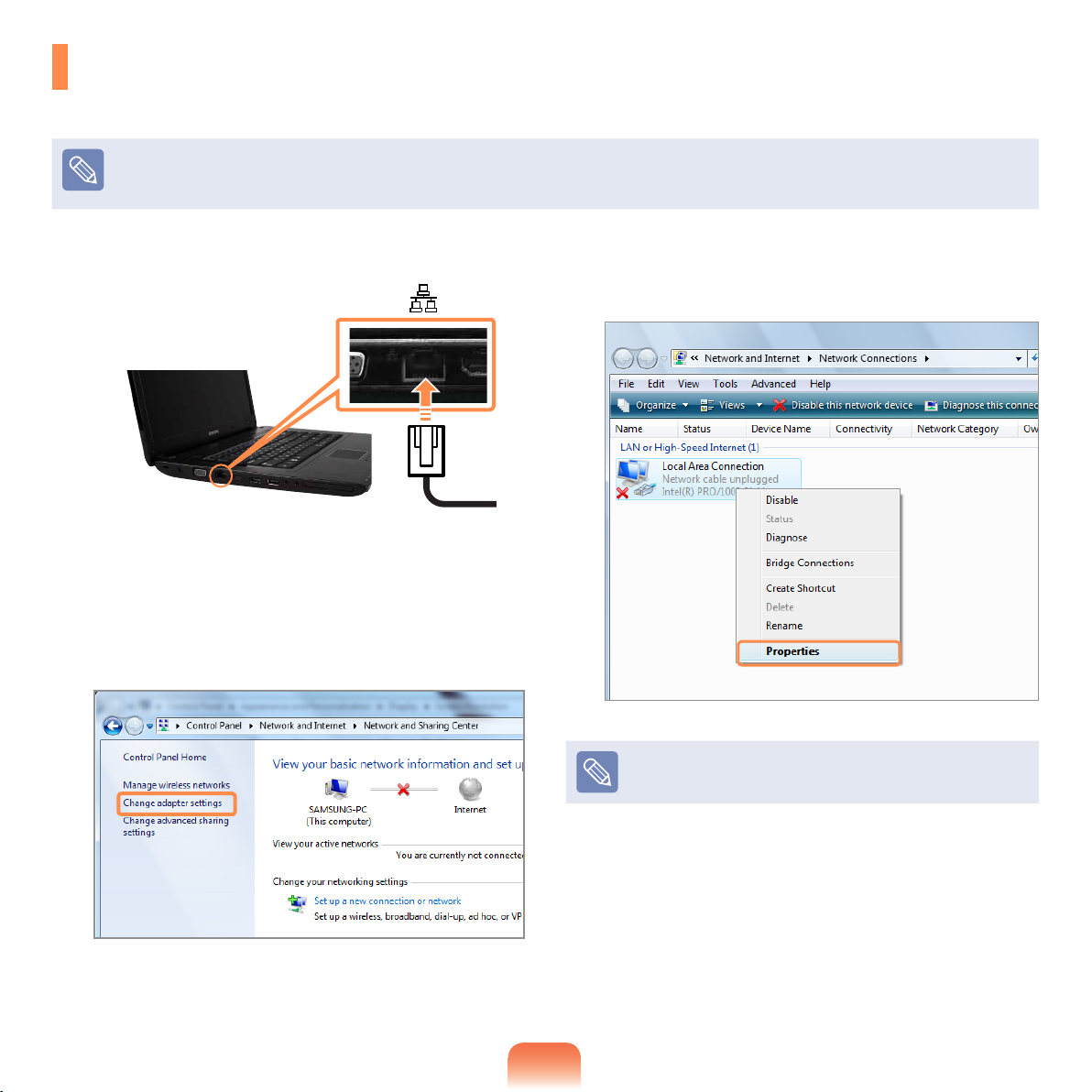
Wired Network
A wired network is a network environment used for a company network or broadband internet connection at home.
Since these descriptions are written on the basis of the latest operating system, Windows 7, some of the content and the gures
of the descriptions may differ depending on the operating system. Since the procedures for other Windows operating systems are
similar, use the computer referring to these descriptions.
Connect a LAN cable to the computer’s LAN port.
1
Click Start > Control Panel > Network and
2
Internet > Network and Sharing Center.
▶ For Windows 7
3
Click the Change adapter settings in the left
menu pane.
Right-click over the Local Area Connection and
4
select Properties.
The LAN Device name may differ depending on your
computer’s Network Device.
▶ For Windows Vista
Click Manage Network Connections from the
left pane.
73
Page 74
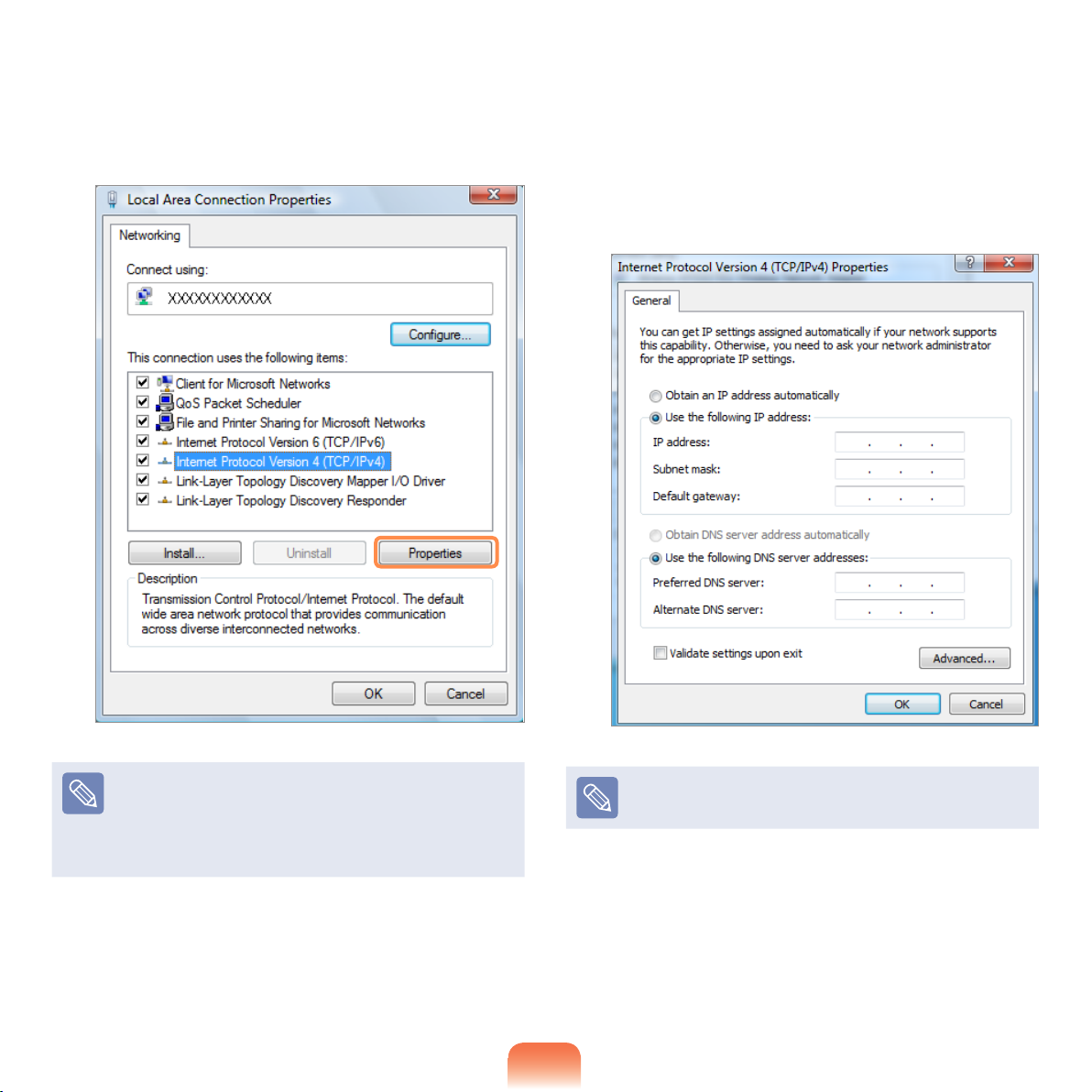
Select Internet Protocol Version 4 (TCP/IPv4)
5
from the Networking tab and click Properties.
Congure the IP settings.
6
When using DHCP, select Obtain an IP address
automatically. To use a static IP address, select
Use the following IP address, and set the IP
address manually.
The LAN device driver may differ depending on your
LAN device model.
To add a network component, click Install in the
screen shown in the gure above. You can add
clients, services, and protocols.
74
When not using DHCP, ask your network administrator
for the IP address.
When you have completed the settings, click the OK
7
button.
The network settings have been completed.
Page 75
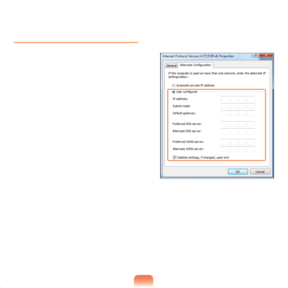
Using both DHCP and a xed IP
simultaneously
Using the Alternate Conguration providing by
Windows Vista, you can set both automatic and xed IP
addresses and then you can select to use either of them
to connect to the Internet.
▶ For Windows 7
1
Click Start > Control Panel > Network and
Internet > Network and Sharing Center and
click on Change adapter settings in the left
menu pane.
For Windows Vista
▶
Click Start > Control Panel > Network and
Internet > Network and Sharing Center and
click Manage Network Connections in the left
pane.
Right-click over the Local Area Connection and
2
select Properties.
Select the Alternate Conguration tab, select User
4
congured, ll in the corresponding elds and click
the OK button.
Select Internet Protocol Version 4 (TCP/IPv4)
3
from the Networking tab and select Properties.
75
Page 76
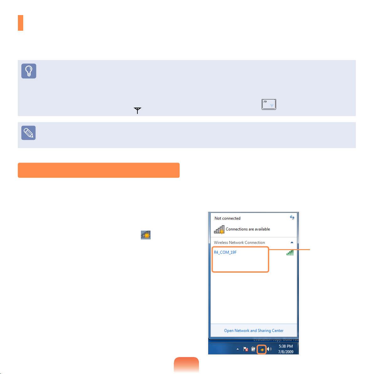
Wireless Network
A wireless network (Wireless LAN) environment is a network environment that enables communicating between
multiple computers at home or a small-size ofce through wireless LAN devices.
Before You Start!
The descriptions below are for computer models with a Wireless LAN card or device.
A Wireless LAN device is optional.
The pictures in this manual may differ from the actual product depending on your wireless LAN device model.
To use the wireless LAN, you have to turn the wireless LAN on rst by pressing the Fn + keys. If the wireless LAN is
turned on, the Wireless LAN LED is lit.
What is an Access Point (AP)?
An AP is a network device that bridges wired and wireless LANs, and corresponds to a wireless hub in a wired network.
You can connect multiple wireless LAN installed computers to an AP.
Connecting to a Wireless LAN
If there is an AP, you can connect to the Internet via the AP using the Wireless LAN connection method provided by
Windows.
▶
For Windows 7
If you click the Network Connections icon in
1
the system tray, a list of available APs appears. If
you select an AP to connect to, the Connect button
appears.
AP List
76
Page 77
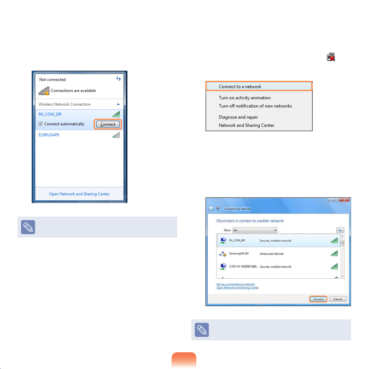
Click Connect.
2
If a network key is set for the AP, enter the network
key and then click Connect.
▶For Windows Vista
Right-click over the Network Connections icon
1
on the taskbar and click Connect to the Network.
Select an AP to connect to and click Connect.
2
If there is a congured network key for the AP to
connect to, the Enter Network Key window appears.
Enter the network key in the window and then click
the Connect button.
For the network key, please ask your network
administrator.
When Connected to the AP is displayed, click the
3
Close button.
You can access the network.
Ask your network administrator for the network key, if
necessary.
77
Page 78
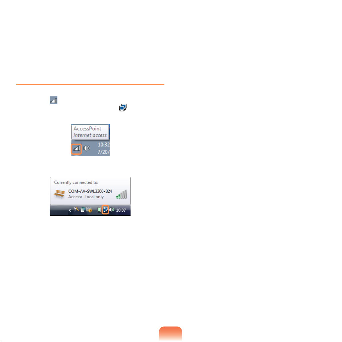
When Connected to the AP is displayed, click the
3
Close button.
You can access the network.
Checking the network connection status
Move the mouse pointer over the Wireless Network
Connection icon on the taskbar, and the connection
status is displayed. (For Windows Vista, )
Windows 7
Windows Vista
78
Page 79

Chapter 3.
Settings and Upgrade
LCD Brightness Control 80
BIOS Setup 81
Entering the BIOS Setup 81
The BIOS Setup Screen 82
Setting a Boot Password 84
Changing the Boot Priority 86
Upgrading Memory 87
Battery 89
Installing/Removing the Battery 89
Charging the Battery 90
Measuring the Remaining Battery Charge 91
Extending the Battery Usage Time 92
Using the Security Lock Port 93
Page 80
80
LCD Brightness Control
You can adjust the LCD brightness in 8 levels.
Before You Start!
The screen brightness is automatically set to the brightest level (brightness level 8) when AC power is connected and the
brightness is automatically set dimmer when the computer runs on battery power to extend the battery use time.
Controlling the Brightness Using the Keyboard
Adjust the LCD brightness by pressing the Fn + key or the Fn + key.
The LCD brightness can change up to 8 levels and the brightness increases by 1 level when pressing the Fn + key
once.
Maintaining the changed LCD brightness even after turning the computer on again
To maintain the LCD brightness set by using the brightness control keys or through the Power Options, follow the procedures
below.
1. Turn the computer on and press the F2 key when the SAMSUNG logo appears on the screen to enter the BIOS Setup.
2. Select the Boot menu and set the Brightness Mode Control item to User Control.
3. Press the F10 key to save the settings and exit Setup.
Saving battery power consumption
Decreases the LCD brightness when the computer is running on battery power to save battery power consumption.
LCD bad pixels principle of laptop computer
Samsung observes the specications regarding strict quality and reliability of LCD. But in spite of that, it is inevitable that there
might be a small number of bad pixels. A large number of bad pixels can cause problems in appearance, but a small number of
pixels doesn’t affect the computer performance.
Therefore Samsung observes and manages the following dot principles:
- Bright dot : 2 or less
- Black dot : 4 or less
- Combination of Bright and Dark : 4 or less
Instructions for Cleaning the LCD
Clean the LCD panel with a soft cloth lightly moistened with computer cleansing detergent moving in one direction.
Cleaning the LCD panel with excessive force can damage the LCD.
Page 81
BIOS Setup
The BIOS Setup enables you to congure your computer hardware according to your needs.
Before You Start!
Use the BIOS setup to dene a boot password, change the booting priority, or add a new device.
Since incorrect settings may cause your system to malfunction or crash, take care when conguring the BIOS.
The functions of the BIOS setup are subject to change for product function enhancement purposes.
The BIOS Setup menus and items may differ depending on your computer model.
Entering the BIOS Setup
Turn the computer on.
1
When the booting screen (SAMSUNG logo) appears,
press the F2 key to enter the BIOS Setup.
2
Press the F12 key while the booting screen(SAMSUNG
logo) appears, the system will try to boot from the
network.
After a moment, the BIOS setup screen appears.
3
The items in the BIOS setup may differ depending
on the product.
81
Page 82
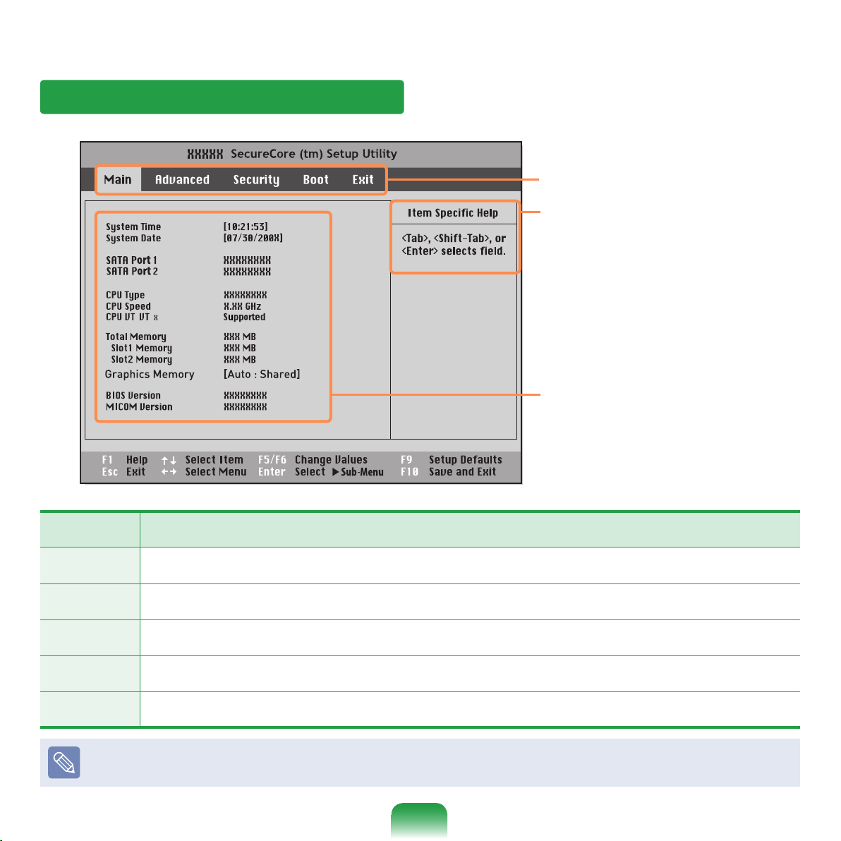
82
The BIOS Setup Screen
(
-
)
Setup Menu
Help
Help for the selected
item appears
automatically.
Setup Items
Setup Menu Description
Main Used to change the basic system and environment settings.
Advanced Used to congure advanced functions on your computer for devices and chipsets.
Security Used to congure security functions, including passwords.
Boot Used to set the boot priority and other boot options
Exit Used to exit the Setup either saving the changes or not.
The BIOS Setup menus and items may differ depending on your computer model.
Page 83
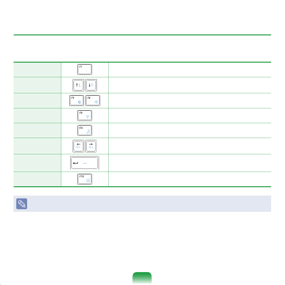
System Setup Keys
In the Setup, you have to use the keyboard.
F1 Press to view the Setup Help.
Up & Down Keys
Press to move up and down.
F5/F6
Press to change the item value.
F9 Press to load the default Setup settings.
ESC Press to return to a higher level menu or to move to the Exit menu.
Left & Right Keys
Press to move to another menu.
Enter Press to select an item or to enter a sub menu.
F10 Press to save the changes and exit Setup.
The keyboard image may differ from the actual keyboard.
83
Page 84
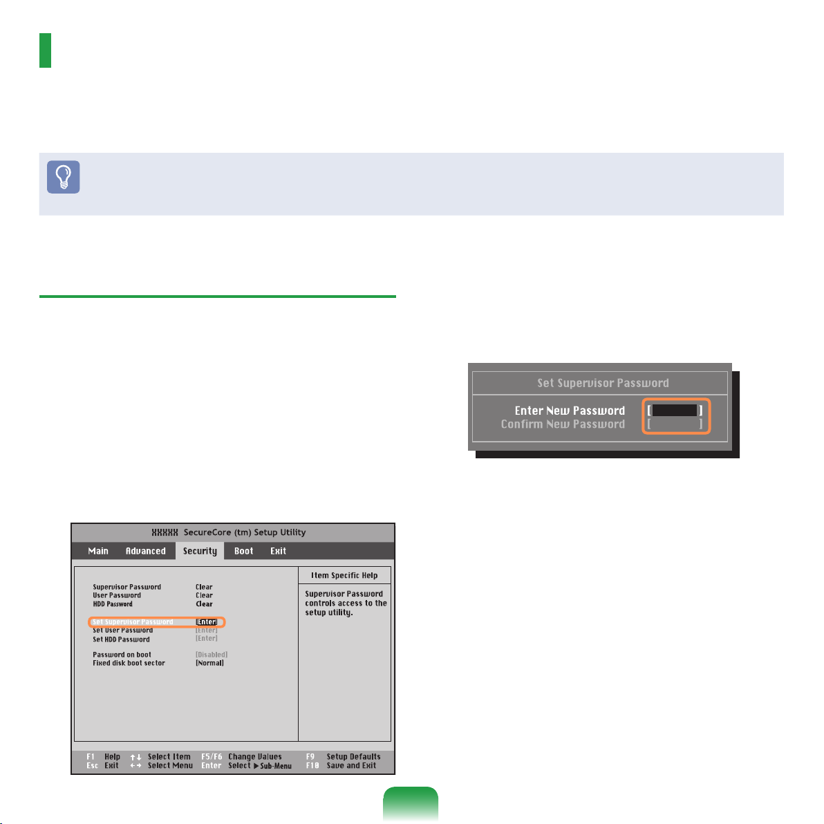
84
Setting a Boot Password
When setting a password, you have to enter a password to use the computer or enter the BIOS Setup.
By conguring a password, you can restrict system access to authorized users only and protect data and les saved
on the computer.
Before You Start!
Do not lose or forget your password.
If you have forgotten your password, contact a Samsung service center. In this case, a service fee will be charged.
Setting a Supervisor Password
A Supervisor Password is required to turn the computer
on or to start the System Setup.
When setting a Supervisor Password, users other than a
supervisor cannot use the computer.
Select the Security menu in the BIOS Setup.
1
In the Set Supervisor Password item, press
2
<Enter>.
Enter a password, press <Enter>, re-enter the
3
password for conrmation, and press <Enter> again.
The password can be up to 8 alphanumeric
characters. Special characters are not allowed.
When a message conrming the password
4
conguration appears in the Setup Notice window,
press <Enter>.
The supervisor password has been set.
The supervisor password is required to turn the
computer on or to enter the BIOS Setup.
Page 85

Setting a User Password
Users can start the system with a user password, but
cannot enter the System Setup. By doing this, you can
prevent other users from entering Setup.
Before conguring a user password, a supervisor
password must have been congured. Deactivating the
supervisor password also deactivates the user password.
In the Set User Password item, press <Enter> and
complete the procedures from Step 3 of Setting a
Supervisor Password.
Changing the hard disk drive password
For security purposes, you can only change a hard
disk drive password after restarting the computer by
pressing the computer Power button.
If you cannot change the hard disk drive password or
the HDD Password Frozen message appears when
entering the BIOS Setup and then selecting Security
> HDD Password, press the Power button to turn the
computer on again.
Deactivating the Password
Setting Up a Boot Password
To setup a boot password, the administrator password
(Set Supervisor Password) should be set in advance.
Set the Password on boot item to Enabled.
Once a boot password is set, you have to enter a
password to boot up the computer.
Setting up a Hard Disk Drive Password
(Optional)
A supervisor password must be set using the Set
Supervisor Password menu.
If you set a password for a hard disk drive, it cannot be
accessed from another computer.
Press <Enter> in the Set HDD Password item and dene
a password as described in Step 3 of the Setting up the
Supervisor Password.
The hard disk drive password setting function is not
provided for some models.
Press <Enter> on the password to be deactivated.
1
For example, to deactivate a supervisor password in
the Set Supervisor Password item, press <Enter>.
In the Enter Current Password item, enter the
2
currently congured password and press <Enter>.
Leave the Enter New Password item eld empty,
3
and press <Enter>.
Leave the Conrm New Password eld empty, and
4
press <Enter>.
In the Setup Notice window, press <Enter>.
5
The password is deactivated.
85
Page 86
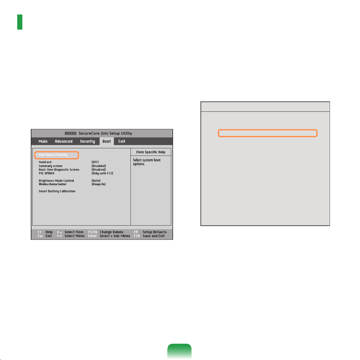
86
Boot Device Priority
[Boot priority order]
1. AHCI CD : N/A
2. AHCI HDD : XXXXXXXXXXXXXXXX
3. USB KEY : N/A
4. USB CD : XXXXXXXXXXXXXX
5. USB FDD : N/A
6. USB HDD : N/A
7. PCI BEV : N/A
8.
- IDE HDD : N/A
- IDE CD : N/A
- PCI SCSI : N/A
- USB ZIP : N/A
- USB LS120 : N/A
[Excluded from boot order]
Changing the Boot Priority
By default, the highest boot priority device is set to the CD-ROM/DVD drive. As an example, the procedures to
change the highest boot priority device to the hard disk drive are described below.
Select the Boot menu in the BIOS Setup.
1
Press <Enter> on the Boot Device Priority item.
2
Press the down key (↓) to move to the AHCI HDD
3
itemand press the F6 key to move up to the top item.
Press the F10 key to save the settings and exit
4
Setup.
The highest boot priority device is now set to the
Hard Drive.
Page 87
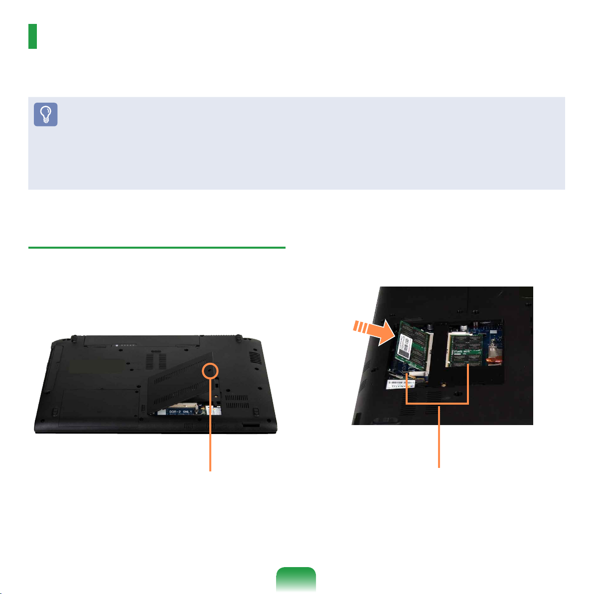
Upgrading Memory
One or more memory modules are installed on the computer.
There are 2 memory slots and users can replace the installed memory or add new memory.
Before You Start!
Replace or install new memory only after shutting the computer down completely. Do not replace or install memory when the
computer is in Sleep mode.
Disconnect main power plug and remove the battery before continuing.
To utilize the dual channel feature, using memory modules with the same specications (of the same capacity and from the
same manufacturer) is recommended.
Only use the same type of memory as specied in the Product Specication.
Adding a Memory Module
Remove the screw on the memory compartment
1
cover at the bottom of the computer using a screw
driver.
Fixing Screw
Insert a new memory module into the memory slot at
2
an angle of approximately 30 degrees aligning it to
the angle of the memory slot.
Memory Slot
87
Page 88
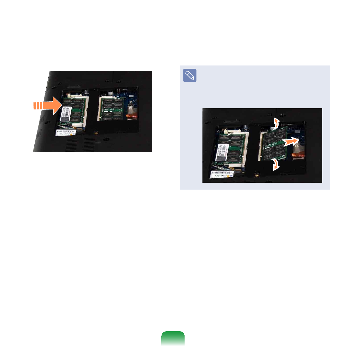
88
Push the memory module down so that it is
3
completely xed. If the memory does not t easily,
push the memory module down while pulling the
memory module latches outward.
Close the memory compartment cover and fasten
4
the screw.
Removing a memory module
Pull the memory module latches outward.
The memory module will pop up.
Remove the memory module out at an angle of 30
degrees.
Page 89
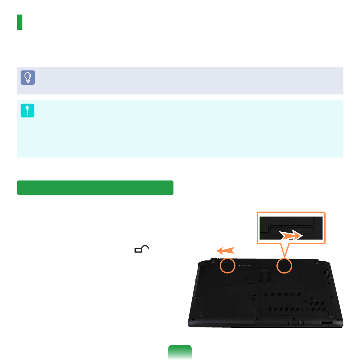
Battery
Please refer to the following instructions when running the computer on battery power without connecting the AC
power.
A Lithium-Ion smart battery is supplied with this computer.
Before You Start!
Carefully read and follow the precautions printed on the battery before using the battery.
Before using your computer for the rst time after purchasing it, charge the battery completely.
Precautions
Use only chargers specied in the User Manual.
Never heat the battery pack, put it near or in a re or use at a temperature higher than 60°C, as this may cause re.
Never cause a short circuit between the battery pack terminals or disassemble the battery pack.
Carefully read and follow the precautions printed on the battery and the safety instructions in the User Manual before using the
battery.
Please refer to the system operation environment of this manual and operate and store the battery at room temperature.
Installing/Removing the Battery
Shutdown the system, close the LCD panel and
1
place the computer upside down on a at surface.
Pull the two battery latches outwards , then
2
remove the battery.
89
Page 90
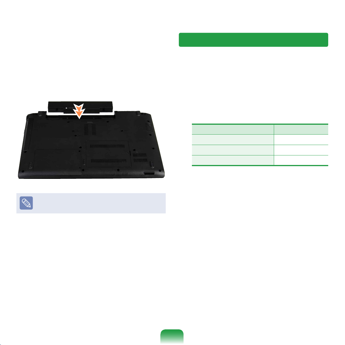
90
Charging the Battery
To install the battery again, slide the battery into the
3
system.
The battery latches move inwards and x the battery
automatically.
Check if the battery latch has been moved inwards.
Attach the battery and connect the AC adapter to the
1
DC-in jack of the computer.
The battery will then start charging.
When charging is complete, the Charge LED turns
2
green.
Status Charge LED
Charging Red
Charging complete Green
AC adapter not connected Off
Page 91
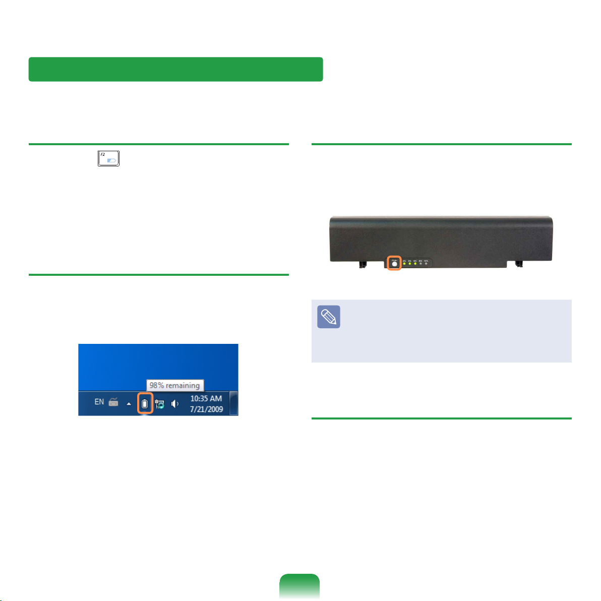
Measuring the Remaining Battery Charge
You can view the battery charge status by completing the following procedures.
To use the shortcut key to view
Press the Fn + keys on the keyboard. The remaining
battery charge (%) will displayed for a moment.
You can only view the charge status in this way when
Easy Display Manager is installed on your computer.
Conrming the battery charge in the
Taskbar
Disconnect the AC adapter and move the mouse cursor
over the battery icon in the system tray of the Taskbar to
conrm the remaining battery charge.
To view on the battery
Separate the battery and press the PUSH button inside
the battery. The remaining battery charge (%) will be
displayed.
Battery Warning
If the battery residual amount is 3~5%, the computer
automatically shuts down after saving the data. The
battery residual amount may vary depending on the
computer model.
Battery Usage Time Information
A battery is an expendable supply, so when using it over
a long time, the capacity/battery life is shortened. If the
battery life is reduced to under half of its initial time, we
recommend purchasing a new battery.
When not using the battery for a long time, store the
battery after charging it to 30-40% of its capacity. This
extends the battery life time.
91
Page 92
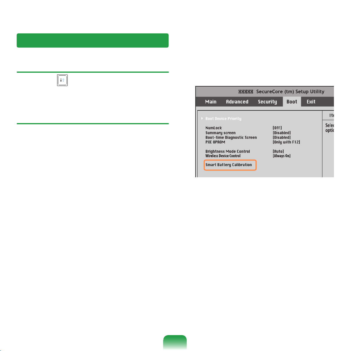
92
Extending the Battery Usage Time
Decreasing the LCD Brightness
Press the Fn + keys on the keyboard to decrease the
LCD brightness to extend the battery usage time.
Using the Battery Calibration Function
When charging/discharging the battery repeatedly for a
short time only, the battery usage time may be reduced by
the difference between the actual battery charge and the
remaining charge display.
In this case, the actual battery charge and the remaining
charge display will be the same by discharging the battery
completely using the Battery Calibration function, and
then recharging it again.
Disconnect the AC power adapter after turning off
1
the computer.
Restart your computer and press the F2 button when
2
the Samsung logo appears, to start the BIOS Setup.
Move to the Boot > Smart Battery Calibration item
3
using the direction keys and press <Enter>.
Highlight Yes in the Battery Calibration
4
Conrmation window and press <Enter>.
The Battery Calibration function is activated and
the battery is forcefully discharged. To stop the
operation, press the <Esc> button.
This operation requires 3~5 hours depending on the
battery capacity and the remaining battery charge.
Page 93
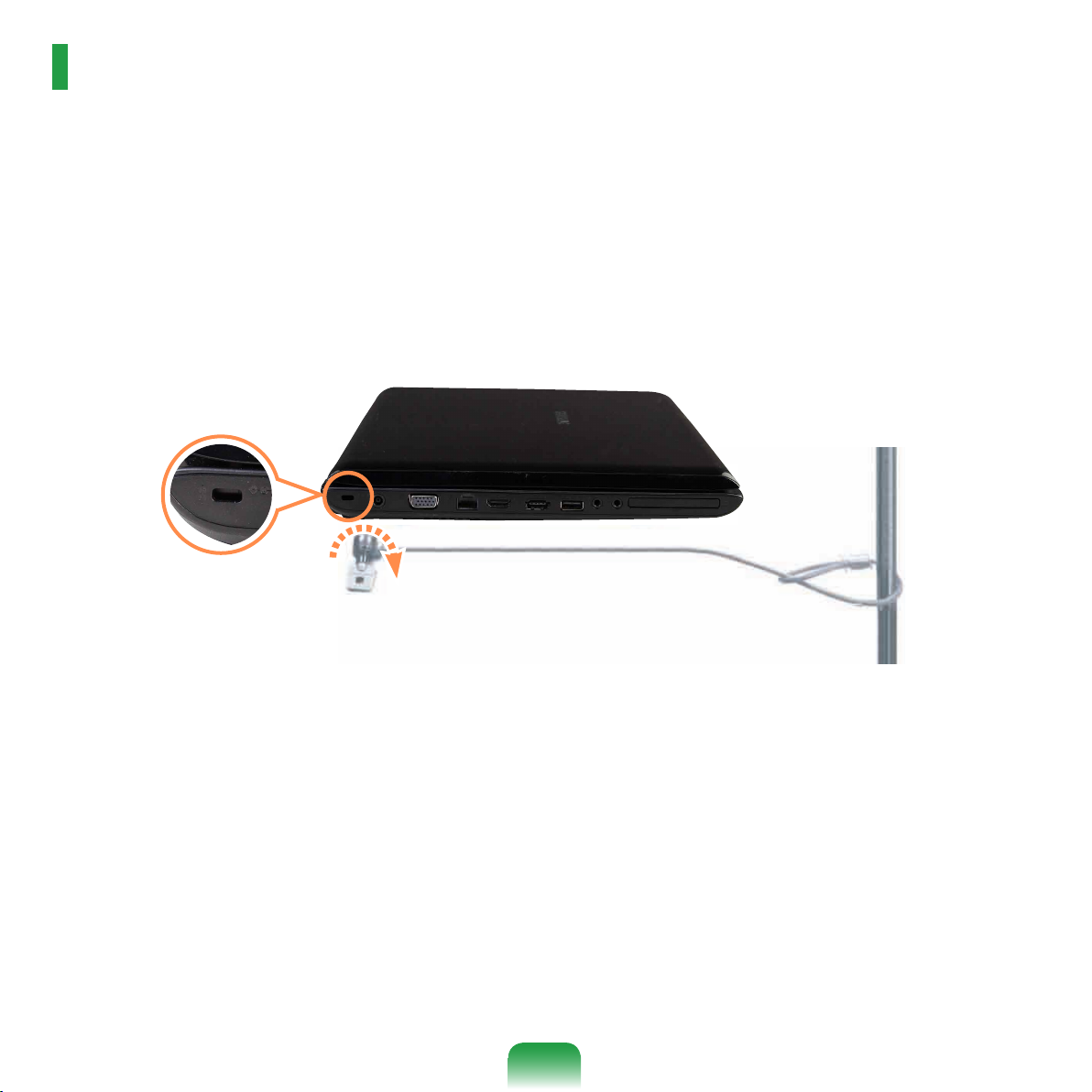
Using the Security Lock Port
You can connect a Kensington lock to the Security Lock port to prevent your computer from being stolen when you
have to use the computer in a public place.
To use this feature, you have to purchase the Kensington lock additionally. To use the Kensington lock, refer to the
product manual.
Tie the Kensington lock cable to a xed object and install the other end of the cable to the Security Lock port.
93
Page 94

Chapter 4.
Troubleshooting
Using Samsung Recovery Solution (Optional) 95
Samsung Recovery Solution Functions 95
Restore Function 98
Backup Function 101
System Software Function 105
Reinstalling Windows 7/Vista
(For Windows 7 and Windows Vista.
For supported models only) 107
Q & A 111
Windows Related 111
Display Related 113
Sound Related 114
Wired Network (LAN) Related 115
Wireless Network (WLAN) Related 117
Game and Program Related 121
Bluetooth 122
Blu-Ray (Optional) 123
Page 95
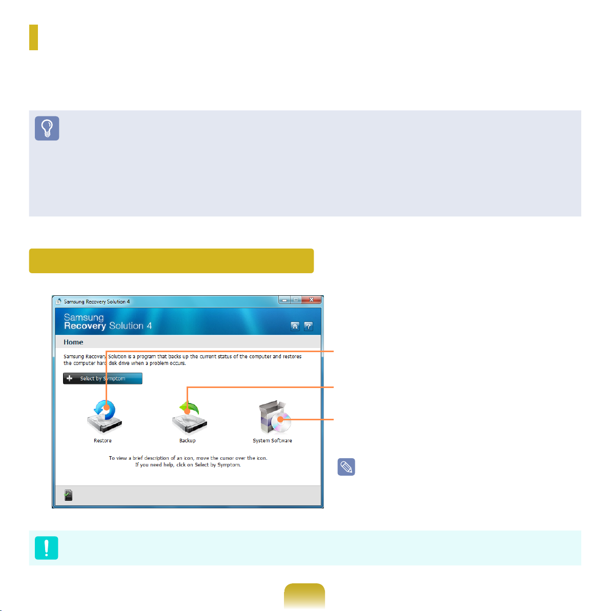
Using Samsung Recovery Solution (Optional)
Samsung Recovery Solution is a program that can backup your hard disk and restores it later when a problem
occurs with your computer. It also provides a System Software function that enables you to install or backup device
drivers and system software programs needed for your system to function properly.
Before You Start!
Samsung Recovery Solution may not be provided or the version may differ depending on the model. In addition, some
functions may not be provided or may differ depending on the version. For more information on using Samsung Recovery
Solution, please refer to the online help of the program.
The screen images in this document may differ from actual product.
If your computer does not have an internal ODD, you need an external ODD connected to your computer to use the Backup
Function or Restore Function using DVDs.
The System Software function may not be provided depending on the program version.
Samsung Recovery Solution Functions
Restore: A function that restores the computer to a
previous state after a problem occurs
B
ackup : A function that backs up the data on the
computer
System Software: A function that reinstalls or backs
up device drivers and application programs needed
for the system
The system software function is supported by
Samsung Recovery Solution version 4 or later.
Therefore, the function may not be supported
depending on the version.
Please back up your important data as data loss may occur for the C drive while restoring/backing up the computer through
Samsung Recovery Solution.
95
Page 96

Restore Function
Using this function, you can easily restore your computer to a previous, stable state when your computer no longer
works properly or you are unable to boot up your computer due to some problem. If you have backed up data, you can
restore the backup data.
Restore Functions
Basic Restore
This function quickly restores
major Windows les (C:\
Windows) without touching the
user conguration and data on
the C drive.
Complete Restore
This function deletes the entire C drive and then
restores the contents of the C drive completely.
Initial Status Restore
This function restores the computer to the initial
status saved when the computer was run for the rst
time after it was purchased.
Complete Backup Restore
This function restores the computer to the point
where the user performed a Complete Backup.
This function restores the user
data if the user previously
backed up data.
Data Restore
Backup Function
You can backup the entire C drive or all your data to another hard disk drive or DVD. You can restore the backed up
drive or data using the Restore function.
Backup Functions
Initial Status Backup
This function backs up the initial
status of the computer.
Complete Backup
This function backs up the entire
drive C.
96
Data Backup
This function backs up specic
folders or les.
Page 97
System Software function
You can back up the System Software saved on the hard disk to another hard disk drive or DVD, and reinstall part or
all software programs to your computer.
System Software function
System Software Installation
This function installs the system software
programs needed for your computer
The system software function is supported by Samsung Recovery Solution version 4 or later. Therefore, the function may
not be supported depending on the version.
You can conrm the version of the current Samsung Recovery Solution in the Samsung Recovery Solution screen.
Example) If the program name that appears in the Samsung Recovery Solution screen is Samsung Recovery Solution 4,
it indicates that the version of the Recovery Solution is version 4. If the name is Samsung Recovery Solution III,
it indicates that the version of the Recovery Solution is version 3.
This function backs up all System Software
Programs
System Software Backup
97
Page 98
Restore Function
Not only can you use Samsung Recovery Solution when Windows is running, but also when you are unable to boot up
into Windows. Let’s learn how to use Samsung Recovery Solution.
Partition Setup & Initial Status Backup
If you turn your computer on for the rst time, the Initial
Status Backup function is performed after registering
Windows. This function saves an image of the Initial
Status of the C drive to a secure location so that users
can restore the computer to the Initial Status using the
Complete Restore function. An Initial Status Backup is
only performed once immediately after the computer is
purchased.
If you turn the power on for the rst time, the
1
Register Windows screen appears. If you register
Windows according to the instructions on the screen,
the computer will be restarted.
After the computer has been restarted, the Partition
2
Setup screen appears.
To resize the C and D drives, adjust the partition size
using the slide bar and the click Next.
The Initial Status Backup screen appears.
3
To continue the Initial Status Backup, click Restart
Now. The computer will restart.
The Initial Status Backup is performed to backup
4
the initial status of the C drive to a secure location.
This backup image is used for the Complete Restore
function that restores your computer to the initial
status.
When the Initial Status Backup is complete, restart
5
Windows.
The Partition Setup function is only available when
the computer is turned on for the rst time and will not
be available afterwards. Once you have completed
the partitioning, it cannot be resized. Partition the disk
carefully.
98
Page 99
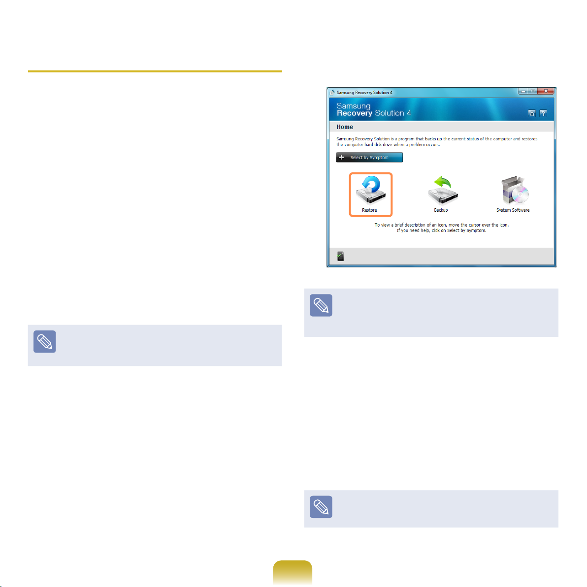
Restoring the computer
Restore is a function that enables restoring the computer
to a saved point when the computer was purchased or a
user-saved point.
The Restore function provides the Basic Restore and
Complete Restore options.
– When Windows is running:
1
Click Start > All Programs > Samsung >
Samsung Recovery Solution > Samsung
Recovery Solution.
– When Windows does not start:
Turn the computer on and press the F4 key when
the boot screen (SAMSUNG logo) appears. After
a moment, the computer boots up in Restoration
mode and the Samsung Recovery Solution screen
appears.
For computers supporting the touch screen function,
the touch screen function does not work during Restore
Mode. In this case, please use the touchpad or mouse.
If the initial menu screen appears, click Restore.
2
If you click Select by Symptom, the Select by
Symptom menu appears. If you select a symptom, a
recommended restoration option will blink. Click the
restoration option to continue.
99
Select either Basic Restore or Complete Restore
3
from the Restore menu.
A Basic Restore restores the major Windows les
only while maintaining the user conguration and
data on the C drive in a short time.
A Complete Restore deletes the entire C drive and
then restores the contents of the C drive.
Run Complete Restore if the computer does not work
even after Basic Restore has been completed.
Page 100
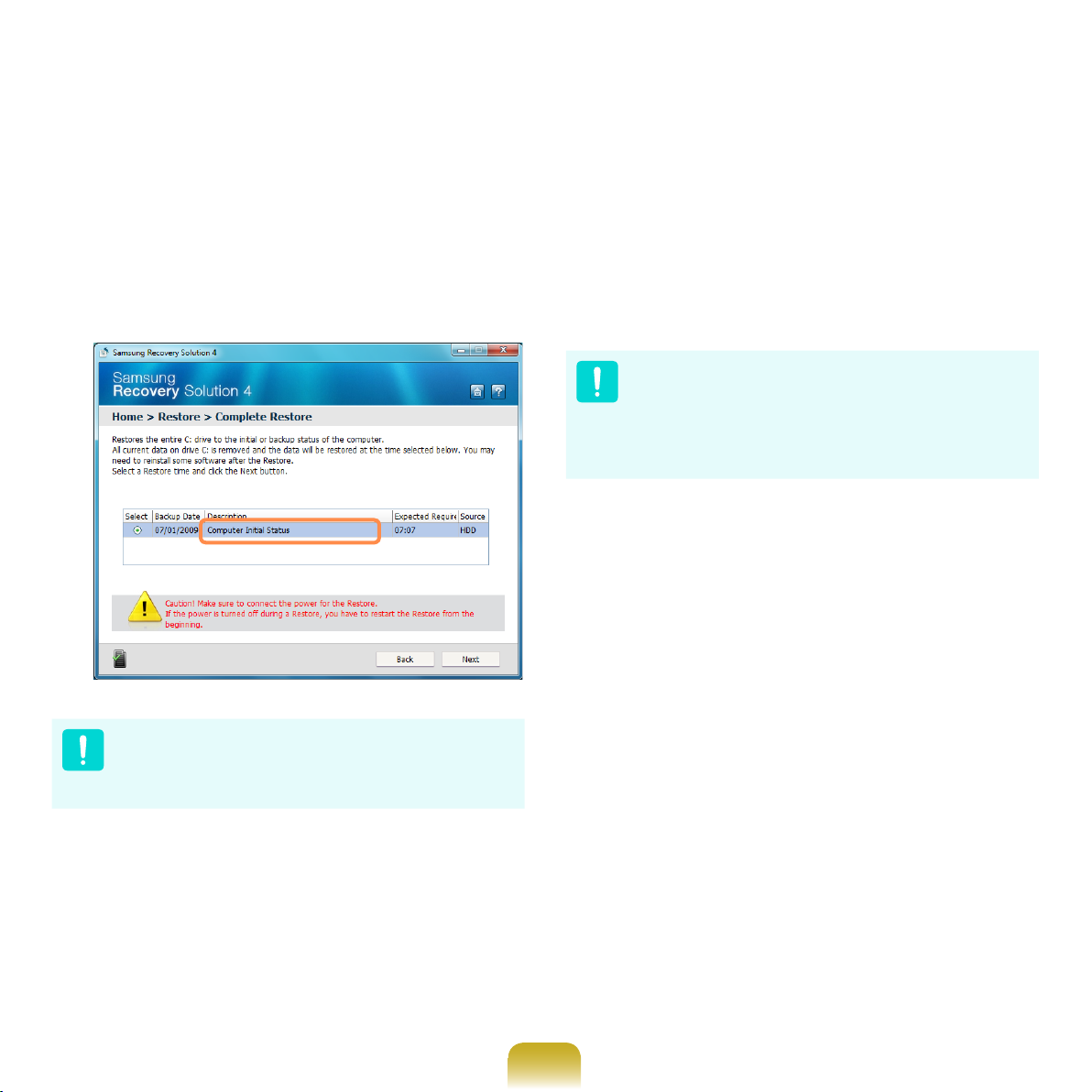
3-1 If you have selected Basic Restore:
In the Basic Restore screen, click the Next button.
The system will be restarted.
If you have selected Complete Restore:
3-2
In the restoration point selection screen, select
the restoration point described as ‘Computer Initial
Status’ and click the Next button. The system will be
restarted.
The computer boots up into restoration mode and
5
the restoration progress message appears. If you
click OK, the restoration begins. The restoration may
take some time, please wait for a moment.
When the ‘Restart the System’ message appears
6
after the restoration is complete, click OK to restart
the system.
Make sure that the power cord is connected while the
restoration is in process. The rst time the computer boots
up after a Complete Restore has been performed, the
speed of the boot process may be slowed down due to the
system optimization process. At this time, do not shut the
computer down by force.
Since a Complete Restore deletes all user data as well
as additionally installed programs, please backup your
important data rst using the Data Backup function,
before running Complete Restore.
If the Samsung Recovery Solution program is
4
launched for the rst time after purchasing the
computer, the license agreement screen appears
before the restoration is started. Read the
agreement and click Agree to continue.
100
 Loading...