

Samsung NP-Q70 Disassembly and Reassembly
- This Document can not be used without Samsung's authorization -
4. Disassembly and Reassembly
4-1. Disassembly and Reassembly of Q70
Part
Name
Figure Description
2
1
2
1
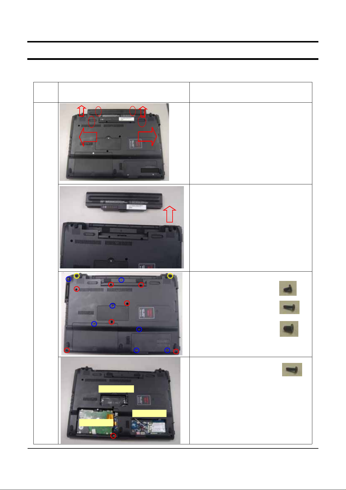
Must remove AC Adapter and Battery
1.
when disassembling system.
After push knobs to end forward to red
2.
arrows and red mark No.1, Push Battery
like red mark No.2.
3.Have Battery with pushing Battery
upward.
Main
System
HDD door
Memory door
4. Remove Bottom Screws.
- M2xL3 : 7 EA (BLUE)
- M2xL7 : 7 EA (RED)
- M3xL5 : 2 EA (YELLOW)
5. Separate HDD DOOR.
- Remove Bottom Screws
-M2xL7 :1 EA(RED)
6. Separate MEMORY Door.
Mincard door
7. Separate Minicard Door.
4-1
- This Document can not be used without Samsung's authorization -
4. Disassembly and Reassembly
Part
Name
Figure Description
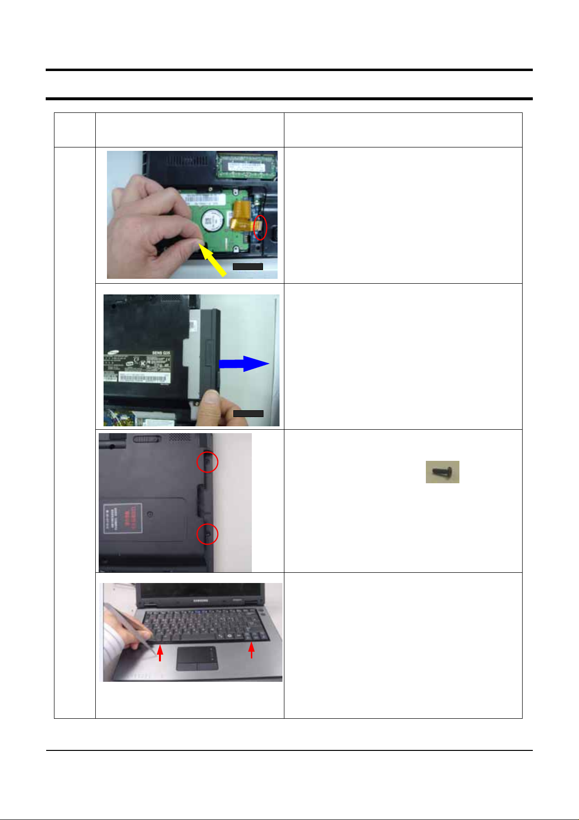
8. You can see HDD, removing Door-HDD,
And, Pick Insulator and pull it toward to 70º
directionthangroundwithHDD.
(And must remove HDD-FPC with operating
connector in red circle in pic.)
*CAUTION
Don’t pull HDD-FPC with too much force.
Must remove HDD before reversing system.
9. Disassemble ODD like pic.
Main
System
10.After removing ODD, remove screws
- M2xL7 : 2 EA(RED)
11. Lift up keyboard after pushing hooks inward
with using tweezers.
*CAUTION
Be careful for Sheet-top scratch when using
tweezers.
4-2
- This Document can not be used without Samsung's authorization -
4. Disassembly and Reassembly
Part
Name
Figure Description
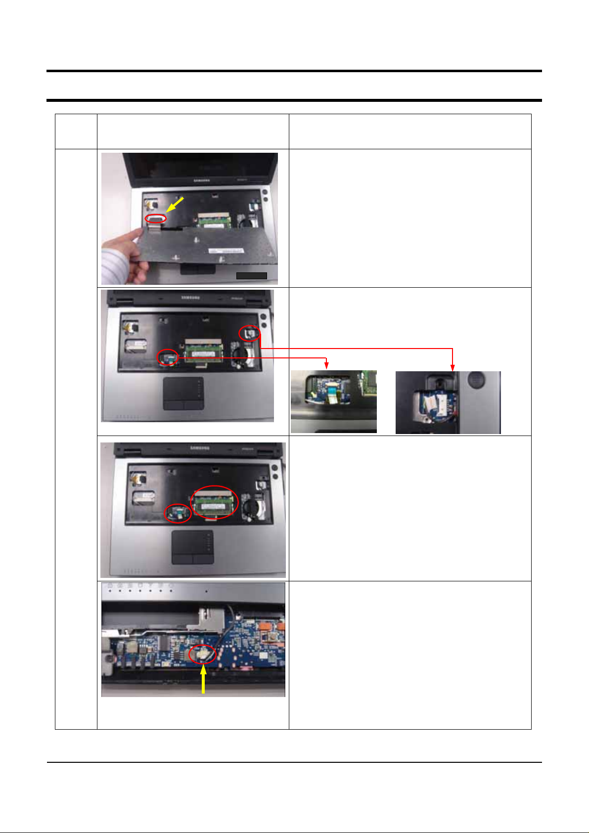
12. After reversing Keyboard backward like pic.
pull out Keyboard FPC with operating Keyboard
Connector.
*CAUTION
Be careful for Sheet-top scratch
13.Separate cables From Main Board.
- Ontop Cable : 1 EA
- Touchpad FFC: 1 EA
Main
System
14.When separate top, separate keyboard tael
section and memory section furtively in bottom
with hand
*CAUTION
AttentionsothatdonotfallMIC-CABLE..
15.Separate MIC-CABLE with picture from main
pcb.
4-3
- This Document can not be used without Samsung's authorization -
4. Disassembly and Reassembly
Part
Name
Figure Description
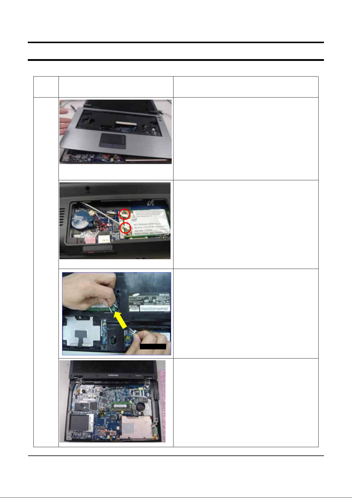
16. Separate perfectly TOP in bottom with
picture.
*CAUTION
Be careful for Sheet-top scratch
17. Separate Antenna Cable connector in
Wireless
LAN module. (Main/AUX)
Main
System
18. Pull Antenna Cable toward to bottom middle
hole like pic.
19. After reversing system, Opening LCD,
and pull out Antenna Cable to main board hole
like pic.
4-4
 Loading...