


- This document cannot be used without Samsung's authorization -
4. Disassembly and Reassembly
4-1. Disassembly and Reassembly of Q35
Part
Figure Description
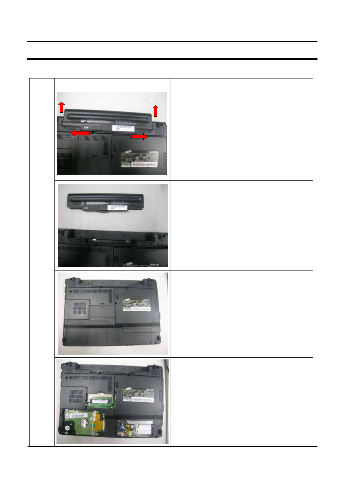
1. Make sure to separate the AC adapter and
battery before disassembling the system.
2. Slide the knob all the way to the end in the
direction of the arrows (1) and push the battery
in the direction of the arrows (2).
3. If you push the battery upwards, the battery
is separated.
Main
System
4. Remove the screws from the bottom.
5. Remove the HDD compartment cover.
6. Remove the memory compartment cover.
7.Remove the minicard compartment cover.
4-1
- This document cannot be used without the authorization of Samsung -
4. Disassembly and Reassembly
Part
Figure Description
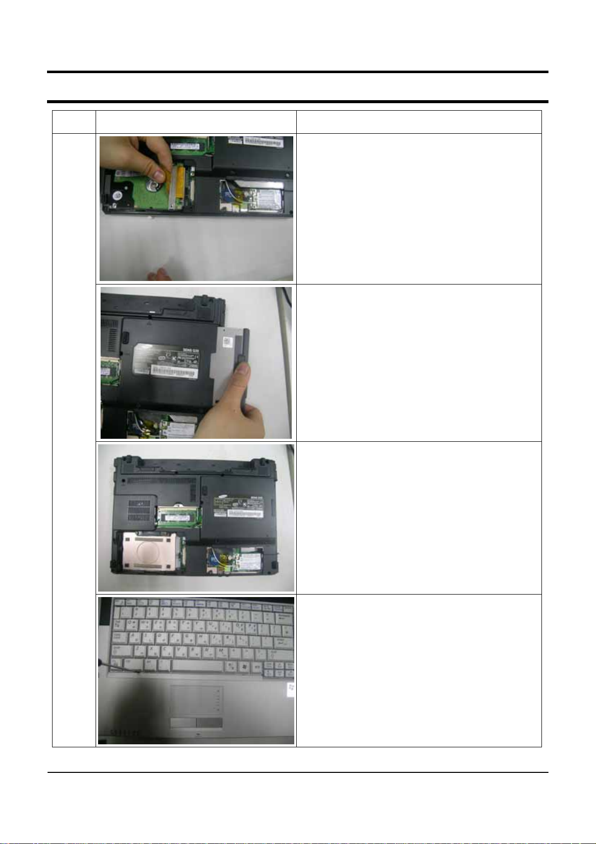
8. When removing the HDD compartment cover,
you will find the HDD. Separate the HDD cable
andliftuptheHDDatanangleof70ºas
showninthefigure.
(To separate the HDD cable, lift up the cable
connector.)
*Caution
DonotlifttheHDDupusingexcessiveforce.
Make sure to remove the HDD before turning
over the system.
9.Separate the ODD as the figure shows.
Main
System
10.RemovescrewsfixedupTOPandBOTTOM
asthefigureshows.
11.Push the hooks inwards using tweezers as
thefigureshowsandliftupthekeyboard.
*Caution
AvoidscratchingtheTopwhenpushingthe
hook with the tweezers.
4-2
- This document cannot be used without the authorization of Samsung -
4. Disassembly and Reassembly
Part
Figure Description
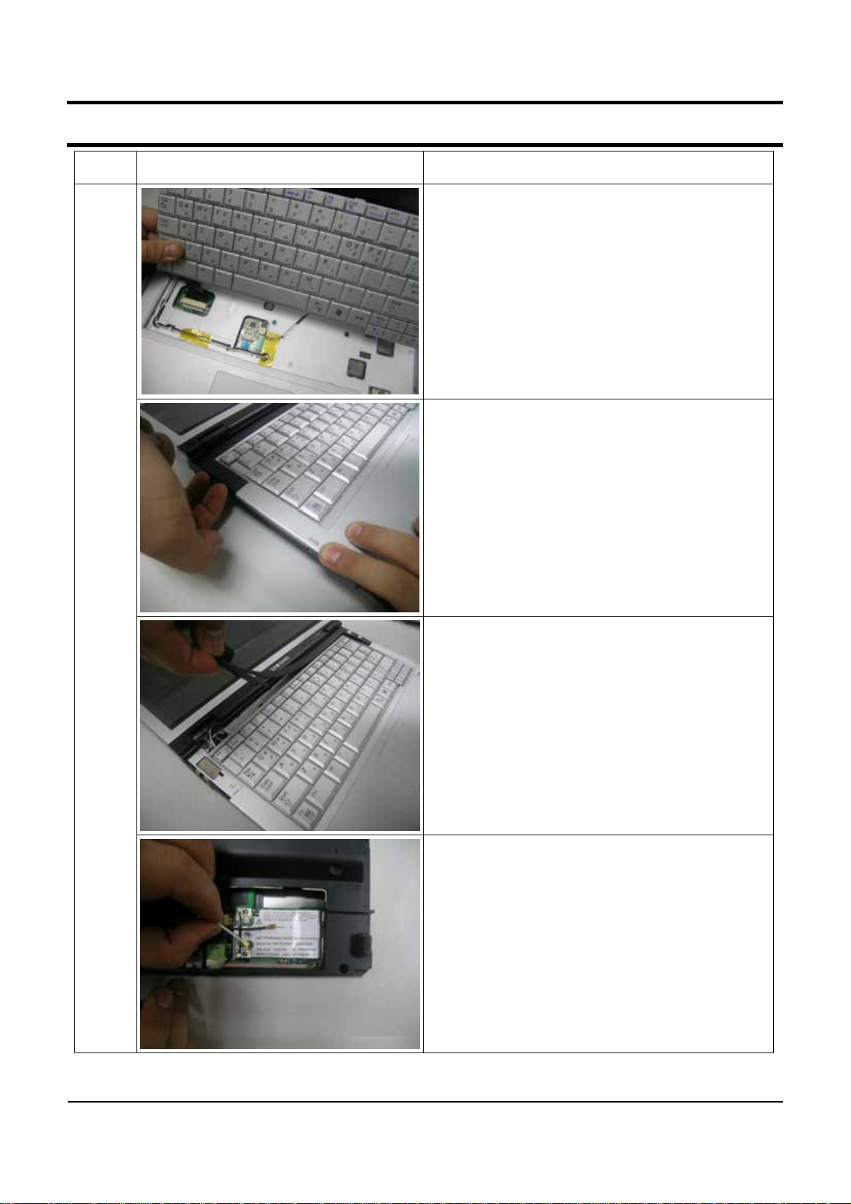
12. Lift up the keyboard, then the Connector
Lock and separate the FPC.
13.1) Lift left side first.
2) Separate Cap-Top lower side to 2 of 3
4) Separate Cap-Top lower side fully
5)
Caution : Be careful to happen scratch on LCD-
Front because of excessive force when you
disassemble Hinge-Cap area.
Main
System
14. Separate the whole Cap-top.
15. Disconnect the antenna cable connected to
the wireless LAN and take the cable out in the
direction of the arrow. (1: Aux,2: Main)
4-3
- This document cannot be used without the authorization of Samsung -
4. Disassembly and Reassembly
Part
Figure Description
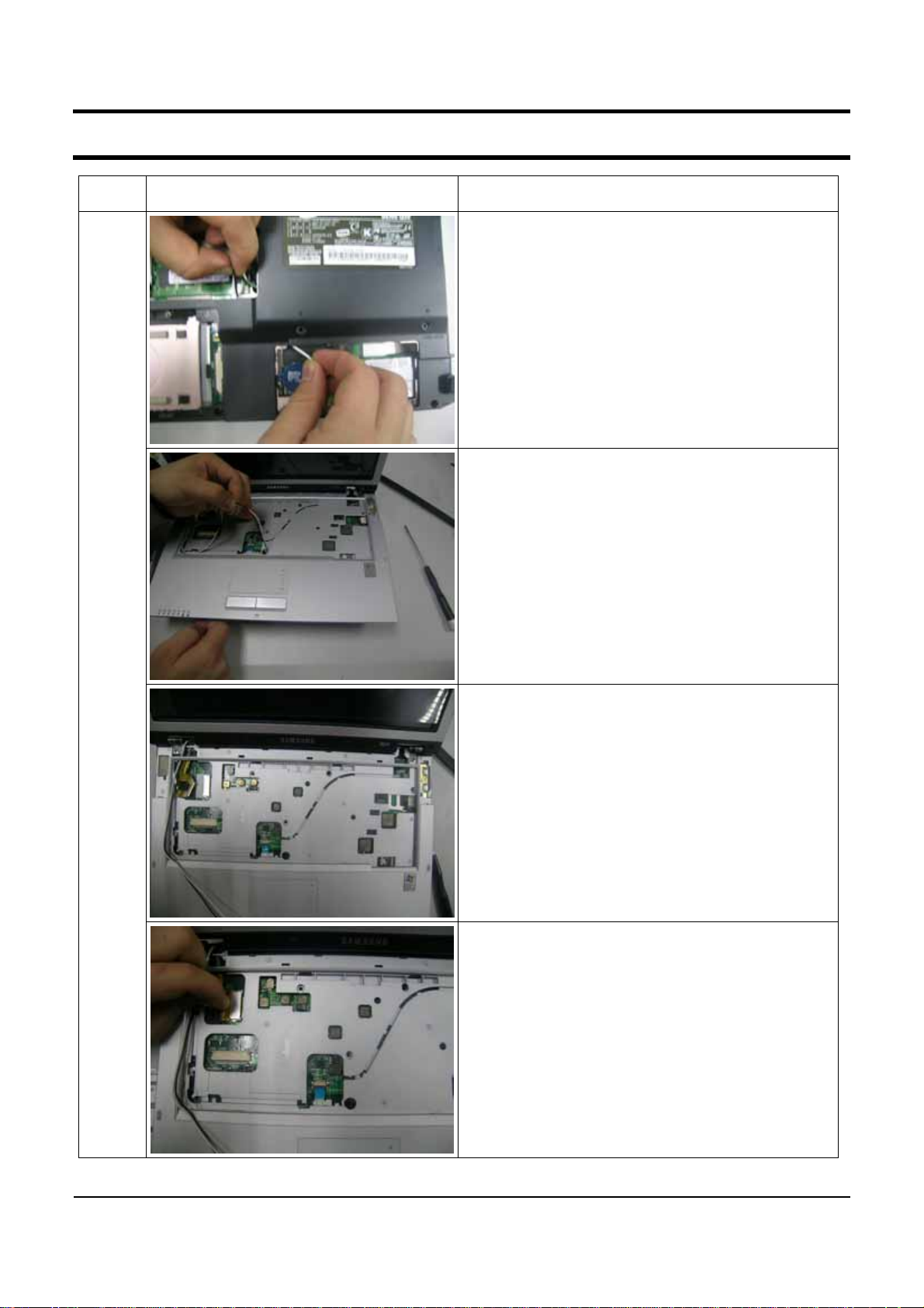
16. Hold and pull the black and white cable in
figure through guideline.
17. Lift up the Assy LCD slightly and separate it
by pulling it in the direction of the arrow.
Main
System
16. Remove the 2 screws fixing the Hinge and
the Top.
19. Separate the LCD cable from MainBD.
4-4