


Samsung NP-Q1 Troubleshooting

- This Documentcan notbe used withoutSamsung's authorization -
5. Troubleshooting
1) General
(1) Tools used for repairing the product
System Diagnostics Disk
MS-DOS Booting Disk
System Diagnostics Card
Screwdrivers (┼,━)
Tweezers
Multi-meter
Oscilloscope
Logic analyzer
(2) Replaceable Units (FRU: Field Replaceable Unit)
DDR2 RAM Module
1.8" SFF HDD
Wireless LAN Module
Bluetooth Module
DMB Module
System Fan
LCD Assy
LCD Inverter
Main Board
Sub Board ? Left Sub Board, Right Sub Board
Harness Cable ? Inverter Cable
Wireless LAN Antenna
DMB Antenna Assy
FFC - Right Sub Board FFC
FPC ? Left Sub Board FPC, LED FPC, HDD FPC, LCD FPC
SENS Q1 < 5 - 1 >
- This Documentcan notbe used withoutSamsung's authorization -
5. Troubleshooting
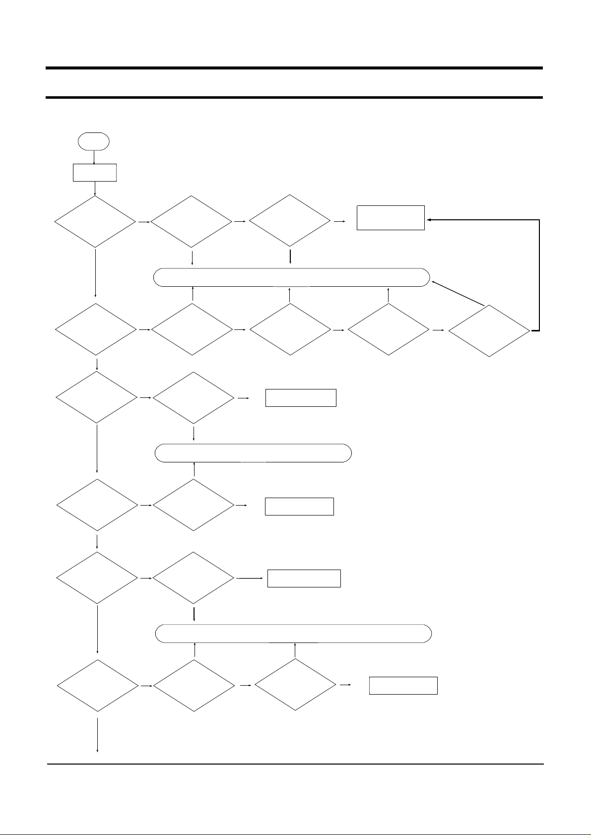
2) Debugging Flow Chart
Start
Poweron
Poweron?
YES
LCD displayis
OK?
YES
FrontBu ttons are OK?
YES
HDD recognition is
OKin CMOS?
No Problems
CheckAdapter& Battery
Itis
problem
Solution:Replace the defected partorrevise the connectivity
Itis
problem
NO
CheckHold SW
NO
NO
CheckSub B'd
FFC & FPC
Connection and
replace it
Itis
problem
Solution:Replace the defected partorrevise the connectivity
Checkthe connection
and change the unit
No
problems
No
problems
Itis
problem
No
problems
Checkthere is
any shortin the
main board
Itis
problem
Itis
problem
CheckRam and
replace it.
ChangeMainboard
and check it
ChangeMainboard
and check it
No Problems
No
problems
ChangeMainboard
and check it
Itis
problem
CheckLcd FPC
Itis
problem
No
problems
No
problems
CheckLCD panel
and Inverter
YES
OSBooting isOK?
YES
TSP function is
OK?
YES
SENS Q1 < 5 - 2 >
NO
NO
OSis corrupted?
Itis
problem
Solution:Replace the defected partorrevise the connectivity
CheckTSP FFC
No
problems
No
problems
ChangeMainboard
and check it
Itis
problem
CheckTouchpad
Interface board
No
problems
ChangeMainboard
and check it
- This Documentcan notbe used withoutSamsung's authorization -
5. Troubleshooting
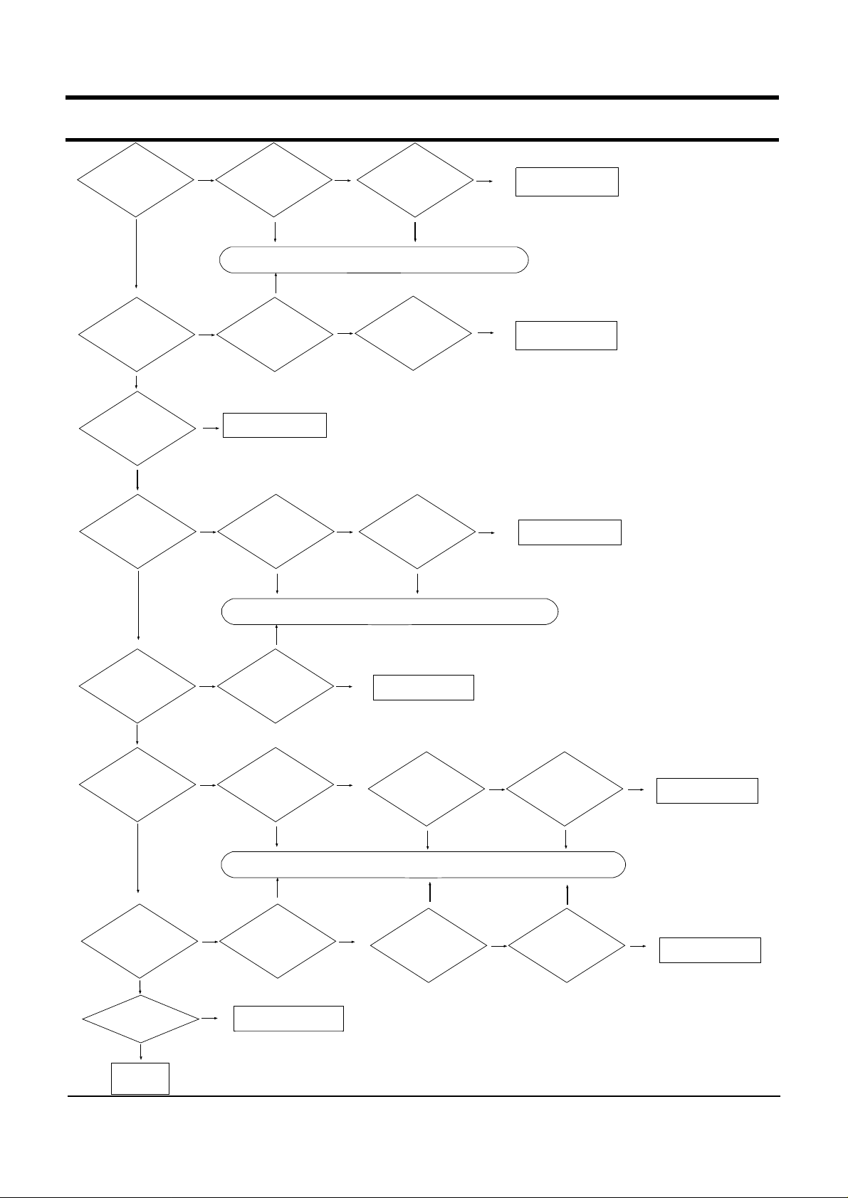
Speaker's sound isOK?
YES
Headphone,MIC
function is OK?
YES
Both side USBs
are OK
YES
CF card function is
OK?
Itis
problem
No
problems
Checkspeaker
connection and
speakercable
NO
Checkdriverstatus
Solution:Replace the defected partorrevise the connectivity
Itis
problem
NO
Checkdriverstatus.
NO
ChangeMainboard
and check it
NO
Checkwhether
pin is bending
NO
No
problems
CheckArray MIC
cable status.
Changedriverstatus
Itis
problem
Itis
problem
No
problems
No
problems
No
problems
ChangeMainboard
and Check it
ChangeMainboard
and it.
ChangeMainboard
and check it
YES
LAN,WLAN
function is OK?
YES
DMB Function
is OK?
YES
Bluetooth
function is OK?
YES
Allfunction is OK?
Itis
problem
Solution:Replace the defected partorrevise the connectivity
Itis
problem
NO
Checkdriverstatus
NO
Checkdriverstatus
Itis
problem
No
problems
No
problems
ChangeMainboard
and check it
CheckDMB Module
Solution:Replace the defected partorrevise the connectivity
Itis
problem
No
NO
NO
Checkdriverstats
ChangeMainboard
and Check it
problems
CheckBluetooth cable
Itis
problem
Itis
problem
Itis
problem
No
problems
No
problems
CheckDMB
AntennaCable
& Antenna
Itis
problem
Itis
problem
CheckBluetooth
module
No
problems
No
problems
ChangeMainboard
and Checkjit
ChangeMainboard
and check it
YES
End
SENS Q1 < 5 - 3 >

- This Documentcan notbe used withoutSamsung's authorization -
5. Troubleshooting
3) System Diagnosis
(1) System Diagnostics Card
The Diagnostics Card shows the system operations during the POST (Power On Self Test) in a
2 digit hexadecimal number by connecting the cable to the 10 pin connector left side the Sodimm
slot after separating the Back Cover. The card is used to evaluate the reason for the malfunction
without disassembling the system when the system malfunctions and to test if the system operates
normally after replacing a defective FRU.
2) Debugging Code
In general, if a defect of the circuit or part is detected during the system test, the system stops at
a particular code. The error codes for each part of the system are listed in the following table.
Code Beeps POST Routine Description
02h Verify Real Mode
03h Disable Non-Maskable Interrupt
04h Get CPU type
06h Initialize system hardware
08h Initialize chipset with initial POST values
09h Set IN POST flag
0Ah Initialize CPU registers
0Bh Enable CPU cache
0Ch Initialize caches to initial POST values
0Eh Initialize I/O component
0Fh Initialize the local bus IDE
10h Initialize Power Management
11h Load alternate registers with initial POST values
12h Restore CPU control word during warm boot
13h Initialize PCI Bus Mastering devices
14h Initialize keyboard controller
16h 1-2-2-3 BIOS ROM checksum
17h Initialize cache before memory auto size
18h 8254 timer initialization
1Ah 8237 DMA controller initialization
1Ch Reset Programmable Interrupt Controller
20h 1-3-1-1 Test DRAM refresh
22h 1-3-1-3 Test 8742 Keyboard Controller
24h Set ES segment register to 4 GB
26h Enable A20 line
28h Auto size DRAM
29h Initialize POST Memory Manager
2Ah Clear 512 KB base RAM
2Ch 1-3-4-1 RAM failure on address line xxxx*
2Eh 1-3-4-3 RAM failure on data bits xxxx* of low byte of memory bus
2Fh Enable cache before system BIOS shadow
30h 1-4-1-1 RAM failure on data bits xxxx* of high byte of memory bus
SENS Q1 < 5 - 4 >

- This Documentcan notbe used withoutSamsung's authorization -
5. Troubleshooting
32h Test CPU bus-clock frequency
33h Initialize Phoenix Dispatch Manager
36h Warm start shut down
38h Shadow system BIOS ROM
3Ah Auto size cache
3Ch Advanced configuration of chipset registers
3Dh Load alternate registers with CMOS values
42h Initialize interrupt vectors
45h POST device initialization
46h 2-1-2-3 Check ROM copyright notice
48h Check video configuration against CMOS
49h Initialize PCI bus and devices
4Ah Initialize all video adapters in system
4Bh Quiet Boot start (optional)
4Ch Shadow video BIOS ROM
4Eh Display BIOS copyright notice
50h Display CPU type and speed
51h Initialize EISA board
52h Test keyboard
54h Set key click if enabled
58h 2-2-3-1 Test for unexpected interrupts
59h Initialize POST display service
5Ah Display prompt "Press F2 to enter SETUP"
5Bh Disable CPU cache
5Ch Test RAM between 512 and 640 KB
60h Test extended memory
62h Test extended memory address lines
64h Jump to UserPatch1
66h Configure advanced cache registers
67h Initialize Multi Processor APIC
68h Enable external and CPU caches
69h Setup System Management Mode (SMM) area
6Ah Display external L2 cache size
6Bh Load custom defaults (optional)
6Ch Display shadow-area message
6Eh Display possible high address for UMB recovery
70h Display error messages
72h Check for configuration errors
76h Check for keyboard errors
7Ch Set up hardware interrupt vectors
7Eh Initialize coprocessor if present
80h Disable onboard Super I/O ports and IRQs
81h Late POST device initialization
82h Detect and install external RS232 ports
83h Configure non-MCD IDE controllers
84h Detect and install external parallel ports
85h Initialize PC-compatible PnP ISA devices
SENS Q1 < 5 - 5 >

- This Documentcan notbe used withoutSamsung's authorization -
5. Troubleshooting
86h Re-initialize onboard I/O ports.
87h Configure Mothe board Configurable Devices (optional)
88h Initialize BIOS Data Area
89h Enable Non-Maskable Interrupts (NMIs)
8Ah Initialize Extended BIOS Data Area
8Bh Test and initialize PS/2 mouse
8Ch Initialize floppy controller
8Fh Determine number of ATA drives (optional)
90h Initialize hard-disk controllers
91h Initialize local-bus hard-disk controllers
92h Jump to UserPatch2
93h Build MPTABLE for multi-processor boards
95h Install CD ROM for boot
96h Clear huge ES segment register
97h Fixup Multi Processor table
98h 1-2 Search for option ROMs. One long, two short beeps on
che checksum failure
99h Check for SMART Drive (optional)
9Ah Shadow option ROMs
9Ch Set up Power Management
9Dh Initialize security engine (optional)
9Eh Enable hardware interrupts
9Fh Determine number of ATA and SCSI drives
A0h Set time of day
A2h Check key lock
A4h Initialize Typematic rate
A8h Erase F2 prompt
AAh Scan for F2 key stroke
ACh Enter SETUP
AEh Clear Boot flag
B0h Check for errors
B2h POST done - prepare to boot operating system
B4h 1 One short beep before boot
B5h Terminate QuietBoot (optional)
B6h Check password (optional)
B9h Prepare Boot
BAh Initialize DMI parameters
BBh Initialize PnP Option ROMs
BCh Clear parity checkers
BDh Display Multi Boot menu
BEh Clear screen (optional)
BFh Check virus and backup reminders
C0h Try to boot with INT 19
C1h Initialize POST Error Manager (PEM)
C2h Initialize error logging
C3h Initialize error display function
C4h Initialize system error handler
C5h PnPnd dual CMOS (optional)
SENS Q1 < 5 - 6 >
- This Documentcan notbe used withoutSamsung's authorization -
5. Troubleshooting
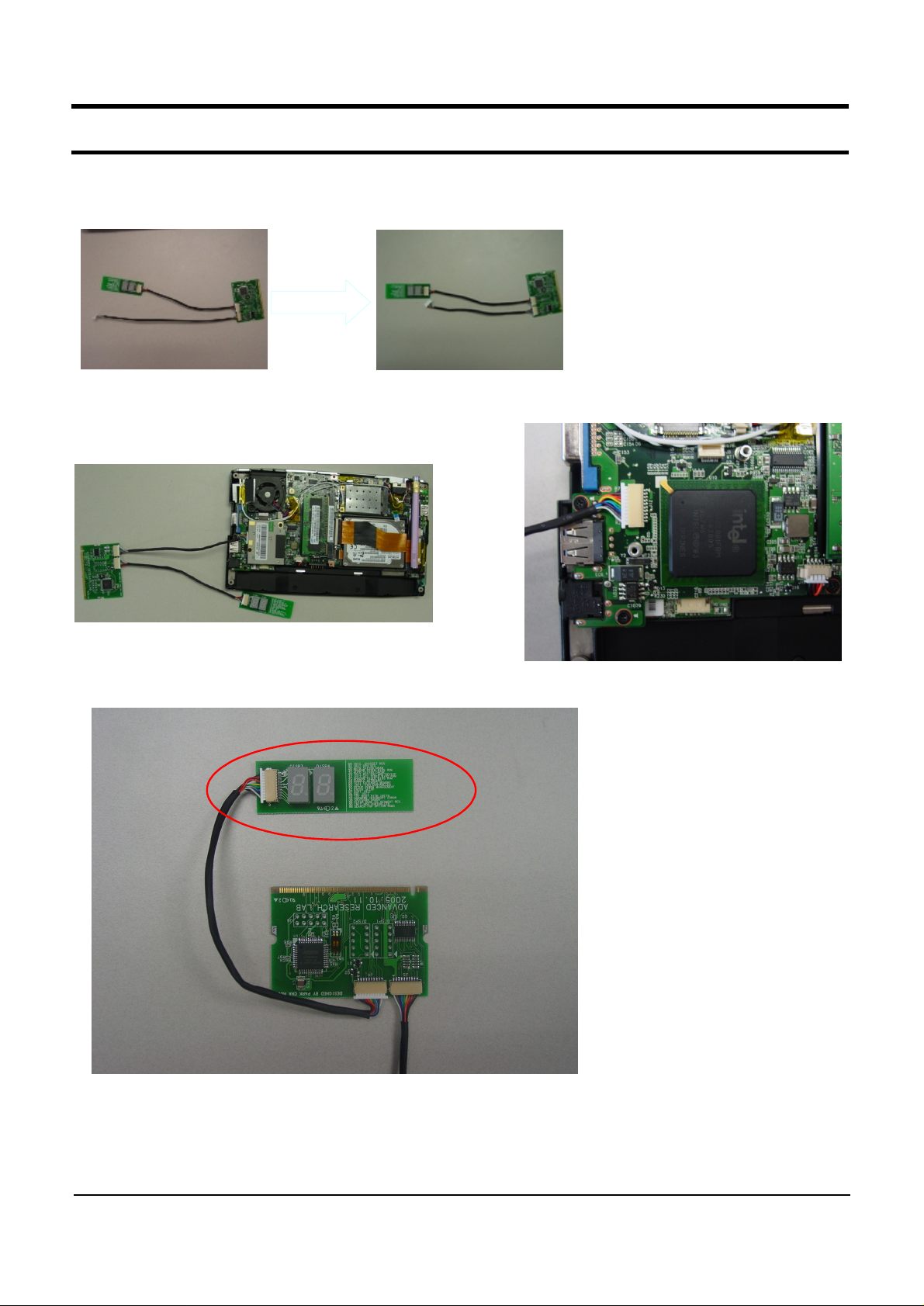
1) Use ofDebug card
-Before use debug card,change the cable ofdebug card.
ⓐ
ⓑ
-Remove cable b from normaldebug card,add anothercable a.(Need 2 cable a)
-.Like upperpicture,debug card is connected to J12 below DM B M odule.
ⓐ
ⓐ
-.Debug code is shown atthe viewer in red line.
SENS Q1 < 5 - 7 >

- This Documentcan notbe used withoutSamsung's authorization -
5. Troubleshooting
4) Hardware Troubleshooting
For the procedures to disassemble each part, refer to the descriptions of Chapter 4,“Disassembly and
Reassembly”.
Before troubleshoot,checkHold SW status.
LCD Related Troubles
◆
1. The screen is dark or the colors of the screen are distorted.
Check the connection status between the LCD module and the LCD FPC, between the LCD
→
FPC and the main board LCD connector and between the LCD and the LCD inverter.
Replace the LCD FPC or LCD inverter.
→
Check if there is a part of the LCD that is bent or broken due to impact.
→
2. No picture appears on the screen.
Check the connection status between the LCD module and the LCD FPC, between the LCD
→
FPC and the main board LCD connector and between the LCD and the LCD inverter.
Replace the LCD FPC or LCD inverter.
→
Check if the System LED of the main board is blinking. (Check if it is operating or not)
→
Check if the memory module is out of order.
→
Check if the Power button can be normally pressed.
→
3. The LCD brightness is not adjusted.
Check if the LCD inverter is out of order.
→
Check the BIOS version and check if the standard adapter is used.
→
Replace the LCD cable or LCD inverter and check if it is out of order.
→
SENS Q1 < 5 - 8 >