

Page 1

Notices
No part of this publication may be reproduced, stored in a retrieval system, or
transmitted, in any form or by any means, mechanical photocopying, recording or
otherwise, without the prior written permission of the manufacturer.
The information within this manual is subject to change without notice.
The manufacturer shall not be held liable for technical or editorial errors or omissions
contained in herein; nor for incidental or consequential damages resulting from the
furnishing, performance or use of this material.
Microsoft Windows is a registered trademark of the Microsoft Corporation.
Product names mentioned herein are for identification purposes only, and may be
trademarks and/or registered trademarks of their respective companies.
Macrovision Statement
If your computer has a DVD drive and an analog TV Out port, the following
paragraph applies:
This product incorporates copyright protection technology that is protected by method
claims of certain U.S. patents and other intellectual property rights owned by
Macrovision Corporation and other rights owners. Use of this copyright protection
technology must be authorized by Macrovision Corporation, and is intended for home
and other limited viewing uses only unless otherwise authorized by Macrovision
Corporation. Reverse engineering or disassembly is prohibited.
Copyright 2002 All rights are reserved
Notices i
Page 2
Important Safety Information
Safety Instructions
Your system is designed and tested to meet the latest standards for safety of
information technology equipment. However, to ensure safe use of this product, it is
important that the safety instructions marked on the product and in the documentation
are followed.
Always follow these instructions to help guard against personal injury and
damage to your system.
i
Setting Up your System
• Read and follow all instructions marked on the product and in the
documentation before you operate your system. Retain all safety and operating
instructions for future use.
• Do not use this product near water or a heat source such as a radiator.
• Set up the system on a stable work surface.
• The product should be operated only with the type of power source indicated on
the rating label.
• Ensure that the electrical outlet you are using to power your equipment is easily
accessible in case of fire or short circuit.
• If your computer has a voltage selector switch, make sure that the switch is in
the proper position for your area.
• Openings in the computer case are provided for ventilation. Do not block or
cover these openings. Make sure you provide adequate space, at least 6 inches
(15 cm), around the system for ventilation when you set up your work area.
Never insert objects of any kind into the computer ventilation openings.
• Ensure that the fan vents on the bottom of the casing are clear at all times. Do
not place the computer on a soft surface, doing so will block the bottom vents.
• If you use an extension cord with this system, make sure that the total ampere
rating on the products plugged into the extension cord does not exceed the
extension cord ampere rating.
ii Users Manual
Page 3
Care During Use
• Do not walk on the power cord or allow anything to rest on it.
• Do not spill anything on the system. The best way to avoid spills is to not eat or
drink near your system.
• Some products have a replaceable CMOS battery on the system board. There is
a danger of explosion if the CMOS battery is replaced incorrectly. Replace the
battery with the same or equivalent type recommended by the manufacturer.
Dispose of batteries according to the manufacturer’s instructions. If the CMOS
battery requires replacement insure that a qualified technician performs the task
• When the computer is turned off, a small amount of electrical current still flows
through the computer. To avoid electrical shock, always unplug all power
cables, remove the battery and modem cables from the wall outlets before
cleaning the system.
• Unplug the system from the wall outlet and refer servicing to qualified
personnel if:
– The power cord or plug is damaged.
– Liquid has been spilled into the system.
– The system does not operate properly when the operating instructions are
followed.
– The system was dropped or the casing is damaged.
– The system performance changes.
Replacement Parts and Accessories
Use only replacement parts and accessories recommended by manufacturer.
To reduce the risk of fire, use only No. 26 AWG or larger telecommunications
line cord.
Do not use this product in areas classified as hazardous. Such areas include
patient care areas of medical and dental facilities, oxygen rich environments,
Writtenby:DarylL. Osden
or industrial areas.
Battery Disposal
Do not put rechargeable batteries or products powered by non-removable
rechargeable batteries in the garbage.
Contact the Samsung Helpline for information on how to dispose of batteries that you
cannot use or recharge any longer.
Follow all local regulations when disposing of old batteries.
Important Safety Information iii
Page 4
Laser Safety
All systems equipped with CD or DVD drives comply with the appropriate safety
standards, including IEC 825. The laser devices in these components are classified as
“Class 1 Laser Products” under a US Department of Health and Human Services
(DHHS) Radiation Performance Standard. Should the unit ever need servicing, contact
an authorized service location.
Laser Safety Note:
Use of controls or adjustments or performance of procedures other than those
specified in this manual may result in hazardous radiation exposure. To
prevent exposure to laser beams, do not try to open the enclosure of a CD or
DVD drive.
Power Cord Requirements
The power cord set (wall plug, cable and AC adapter plug) you received with your
computer meets the requirements for use in the country where you purchased your
equipment.
Power cord sets for use in other countries must meet the requirements of the country
where you use the computer. For more information on power cord set requirements,
contact your authorized dealer, reseller, or service provider.
General Requirements
The requirements listed below are applicable to all countries:
• The length of the power cord set must be at least 6.00 feet (1.8m) and a
maximum of 9.75 feet (3.0m).
• All power cord sets must be approved by an acceptable accredited agency
responsible for evaluation in the country where the power cord set will be used.
• The power cord set must have a minimum current capacity of 7 A and a
nominal voltage rating of 125 or 250 volts AC, as required by each country’s
power system.
• The appliance coupler must meet the mechanical configuration of an EN 60
320/IEC 320 Standard Sheet C7 connector, for mating with appliance inlet on
the computer.
iv Users Manual
Page 5
Regulatory Compliance Statements
Wireless Guidance
Low power, Radio LAN type devices (radio frequency (RF) wireless communication
devices), operating in the 2.4 GHz Band, may be present (embedded) in your notebook
system. The following section is a general overview of considerations while operating
a wireless device.
Additional limitations, cautions, and concerns for specific countries are listed in the
specific country sections (or country group sections). The wireless devices in your
system are only qualified for use in the countries identified by the Radio Approval
Marks on the system rating label. If the country you will be using the wireless device
in, is not listed, please contact your local Radio Approval agency for requirements.
Wireless devices are closely regulated and use may not be allowed.
The power output of the wireless device or devices that may be embedded in your
notebook is well below the RF exposure limits as known at this time. Because the
wireless devices (which may be embedded into your notebook) emit less energy than
is allowed in radio frequency safety standards and recommendations, manufacturer
believes these devices are safe for use. Regardless of the power levels, care should be
taken to minimize human contact during normal operation.
As a general guideline, a separation of 20 cm (8 inches) between the wireless device
and the body, for use of a wireless device near the body (this does not include
extremities) is typical. This device should be used more than 20 cm (8 inches) from the
body when wireless devices are on and transmitting.
This transmitter must not be collocated or operate in conjunction with any other
antenna or transmitter.
Some circumstances require restrictions on wireless devices. Examples of common
restrictions are listed below:
Radio frequency wireless communication can interfere with equipment on
commercial aircraft. Current aviation regulations require wireless devices to be
turned off while traveling in an airplane. 802.11B (also known as wireless
Ethernet or Wifi) and Bluetooth communication devices are examples of
devices that provide wireless communication.
Regulatory Compliance Statements v
Page 6

In environments where the risk of interference to other devices or services is
harmful or perceived as harmful, the option to use a wireless device may be
restricted or eliminated. Airports, Hospitals, and Oxygen or flammable gas
laden atmospheres are limited examples where use of wireless devices may
be restricted or eliminated. When in environments where you are uncertain of
the sanction to use wireless devices, ask the applicable authority for
authorization prior to use or turning on the wireless device.
Every country has different restrictions on the use of wireless devices. Since
your system is equipped with a wireless device, when traveling between
countries with your system, check with the local Radio Approval authorities
prior to any move or trip for any restrictions on the use of a wireless device in
the destination country.
If your system came equipped with an internal embedded wireless device, do
not operate the wireless device unless all covers and shields are in place and
the system is fully assembled.
Wireless devices are not user serviceable. Do not modify them in any way.
Modification to a wireless device will void the authorization to use it. Please
contact manufacturer for service.
Only use drivers approved for the country in which the device will be used. See
the manufacturer System Restoration Kit, or contact manufacturer Technical
Support for additional information.
vi Users Manual
Page 7

United States of America
Unintentional Emitter per FCC Part 15
This device complies with Part 15 of the FCC Rules. Operation is subject to the
following two conditions:(1) this device may not cause harmful interference, and (2)
this device must accept any interference received, including interference that may
cause undesired operation.
This equipment has been tested and found to comply with the limits for a Class
B digital device pursuant to Part 15 of the FCC Rules. These limits are
Writtenby:DarylL. Osden
If necessary, the user should consult the dealer or an experienced radio/television
technician for additional suggestions. The user may find the following booklet helpful:
“Something About Interference.” This is available at FCC local regional offices. Our
company is not responsible for any radio or television interference caused by
unauthorized modifications of this equipment or the substitution or attachment of
connecting cables and equipment other than those specified by our company. The
correction will be the responsibility of the user. Use only shielded data cables with this
system.
designed to provide reasonable protection against harmful interference in a
residential installation. This equipment generate uses and can radiate radio
frequency energy and if not installed and used in accordance with the
instructions may cause harmful interference will not occur in a particular
installation. If this equipment does cause harmful interference to radio or
television reception, which can be determined by turning the equipment off
and on, the user is encouraged to try to correct the interference by one or more
of the following measures:
• Reorient or relocate the receiving antenna.
• Increase the separation between the equipment and receiver.
• Connect the equipment into an outlet on a circuit different from that
to which the receiver is connected.
• Consult the dealer or an experienced radio/TV technician for help.
Intentional emitter per FCC Part 15
Low power, Radio LAN type devices (radio frequency (RF) wireless communication
devices), operating in the 2.4 GHz Band, may be present (embedded) in your notebook
system. This section is only applicable if these devices are present. Refer to the system
label to verify the presence of wireless devices.
Wireless devices that may be in your system are only qualified for use in the United
States of America if an FCC ID number is on the system label.
Regulatory Compliance Statements vii
Page 8
The FCC has set a general guideline of 20 cm (8 inches) separation between the device
and the body, for use of a wireless device near the body (this does not include
extremities). This device should be used more than 20 cm (8 inches) from the body
when wireless devices are on. The power output of the wireless device (or devices),
which may be embedded in your notebook, is well below the RF exposure limits as set
by the FCC.
This transmitter must not be collocated or operate in conjunction with any other
antenna or transmitter.
Operation of this device is subject to the following two conditions: (1) This device may
not cause harmful interference, and (2) this device must accept any interference
received, including interference that may cause undesired operation of the device.
Wireless devices are not user serviceable. Do not modify them in any way.
Modification to a wireless device will void the authorization to use it. Contact
manufacturer for service.
FCC Statement for Wireless LAN use:
“While installing and operating this transmitter and antenna combination the
radio frequency exposure limit of 1mW/cm2 may be exceeded at distances
close to the antenna installed. Therefore, the user must maintain a minimum
distance of 20cm from the antenna at all times. This device can not be
colocated with another transmitter and transmitting antenna.”
FCC Part 68
This equipment compiles with part of the FCC rules. On the back of this equipment is
a label that contains, among other information, the FCC registration number and ringer
equivalence number (REN) for this equipment. If requested, this information must be
provided to the telephone company.
This equipment uses the following USOC jacks : RJ11C
An FCC compliant telephone cord and modular plug is provided with this equipment.
This equipment is designed to be connected to the telephone network or promises
wiring using a compatible modular jack which is Part 68 compliant. See Installation
Instructions for details.
The REN is used to determine the quantity of devices which may be connected to
telephone line. Excessive RENs on the telephone line may result in the devices not
ringing in response to an incoming call. In most, but not all areas, the sum of RENs
should not exceed five (5.0). To be certain of the number of devices that may be
connected to a line, as determined by total RENs, contact the local telephone company
to determine the maximum REN for the calling area.
viii Users Manual
Page 9

If the terminal equipment causes harm to the telephone network, the Telephone
Company will notify you in advance that temporary discontinuance of service may be
required. But if advance notice is not practical, the telephone company will notify the
customer as soon as possible. Also, you will be advised of your right to file a complaint
with the FCC if you believe it is necessary.
The telephone company may make changes in its facilities, equipment, operations, or
procedures that could affect the operation of the equipment. If this happens, the
telephone company will provide advanced notice in order for you to make necessary
modifications to maintain uninterrupted service.
If trouble is experienced with this equipment (Modem) for repair or warranty
information, please contact your local distributor. If the equipment is causing harm to
the telephone network, the telephone company may request that you disconnect the
equipment until the problem is resolved.
The user must use the accessories and cables supplied by the manufacturer to get
optimum performance from the product.
No repairs may be done by the customer.
This equipment cannot be used on public coin phone service provided by the telephone
company. Connection to party line service is subject to state tariffs.
The Telephone Consumer Protection Act of 1991 makes it unlawful for any person to
use a computer or other electronic device, including fax machines, to send any message
unless such message clearly contains in a margin at the top or bottom of each
transmitted page or on the first page of the transmission, the date and time it is sent and
an identification of the business or other entity, or other individual sending the message
and the telephone number of the sending machine or such business, other entity, or
individual. (The telephone number provided may not be any number for which charges
exceed local or long-distance transmission charges.)
In order to program this information into your fax machine, refer to your
communications software user manual.
Regulatory Compliance Statements ix
Page 10

Canada
Unintentional Emitter per ICES-003
This digital apparatus does not exceed the Class B limits for radio noise emissions from
digital apparatus as set out in the radio interference regulations of Industry Canada.
Le présent appareil numérique n’émet pas de bruits radioélectriques dépassant les
limitesapplicables aux appareils numériques de Classe B prescrites dans le règlement
sur le brouillage radioélectrique édicté par Industrie Canada.
Intentional Emitter per RSS 210
Low power, Radio LAN type devices (radio frequency (RF) wireless communication
devices), operating in the 2.4 GHz Band, may be present (embedded) in your notebook
system. This section is only applicable if these devices are present. Refer to the system
label to verify the presence of wireless devices.
Wireless devices that may be in your system are only qualified for use in Canada if an
Industry Canada ID number is on the system label.
As a general guideline, a separation of 20 cm (8 inches) between the wireless device
and the body, for use of a wireless device near the body (this does not include
extremities) is typical. This device should be used more than 20 cm (8 inches) from the
body when wireless devices are on.
The power output of the wireless device (or devices), which may be embedded in your
notebook, is well below the RF exposure limits as set by Industry Canada.
This transmitter must not be collocated or operate in conjunction with any other
antenna or transmitter.
Operation of this device is subject to the following two conditions: (1) This device may
not cause harmful interference, and (2) this device must accept any interference
received, including interference that may cause undesired operation of the device.
x Users Manual
To prevent radio interference to licensed service, this device is intended to be
operated indoors and away from windows to provide maximum shielding.
Equipment (or its transmit antenna) that is installed outdoors is subject to
licensing.
Wireless devices are not user serviceable. Do not modify them in any way.
Modification to a wireless device will void the authorization to use it. Contact
manufacturer for service.
Page 11

Telecommunications per DOC notice (for products fitted with an IC-compliant modem)
The Industry Canada label identifies certified equipment. This certification means that
the equipment meets certain telecommunications network protective, operation, and
safety requirements. The Department does not guarantee the equipment will operate to
the users’ satisfaction.
Before installing this equipment, users should make sure that it is permissible to be
connected to the facilities of the local telecommunications company. The equipment
must also be installed using an acceptable method of connection. In some cases, the
inside wiring associated with a single-line individual service may be extended by
means of a certified connector assembly. The customer should be aware that
compliance with the above conditions may not prevent degradation of service in some
situations.
Repairs to certified equipment should be made by an authorized Canadian maintenance
facility designated by the supplier. Any repairs or alterations made by the user to this
equipment, or equipment malfunctions, may give the telecommunications company
cause to request the user to disconnect the equipment.
Users should make sure, for their own protection, that the electrical ground connections
of the power utility, telephone lines, and internal metallic water pipe system, if present,
are connected together. This precaution may be particularly important in rural areas.
To avoid electrical shock or equipment malfunction do not attempt to make
electrical ground connections by yourself. Contact the appropriate inspection
authority or an electrician, as appropriate.
The Ringer Equivalence Number (REN) assigned to each terminal device provides
an indication of the maximum number of terminals allowed to be connected to a
telephone interface. The termination on an interface may consist of any combination of
devices subject only to the requirement that the sum of the Ringer Equivalence
Numbers of all the devices does not exceed 5.
Regulatory Compliance Statements xi
Page 12

European Union
The following information is only applicable to systems labeled with the CE mark .
European Directives
This Information Technology Equipment has been tested and found to comply with the
following European directives:
• EMC Directive 89/336/EEC with amending directives 92/31/EEC & 93/68/
EEC as per
– EN 55022 Class B
– EN 61000-3-2
– EN 61000-3-3
– EN 55024
• Low Voltage Directive (Safety) 73/23/EEC as per EN 60950(A1/A2/A3/A4/
A11)
• Radio and Telecom Terminal Equipment Directive 199/5/EC as per
– CTR21 (if fitted with a modem device)
– ETS 300 328 (if fitted with a 2.4 GHz band embedded wireless device)
– ETS 301 489-1 (if fitted with a 2.4 GHz band embedded wireless device)
– ETS 301 489-17 (if fitted with a 2.4 GHz band embedded wireless device)
European Radio Approval Information (for products fitted with EU-approved radio devices)
This Product is a Notebook computer; low power, Radio LAN type devices (radio
frequency (RF) wireless communication devices), operating in the 2.4 GHz band, may
be present (embedded) in your notebook system which is intended for home or office
use. This section is only applicable if these devices are present. Refer to the system
label to verify the presence of wireless devices.
Wireless devices that may be in your system are only qualified for use in the European
Union or associated areas if a CE mark with a Notified Body Registration Number
and the Alert Symbol is on the system label.
The power output of the wireless device or devices that may be embedded in you
notebook is well below the RF exposure limits as set by the European Commission
through the R&TTE directive.
xii Users Manual
Page 13

European States qualified under wireless approvals:
EU
Austria, Belgium, Denmark, Finland, France (with frequency
restrictions),
Germany, Greece, Ireland, Italy, Luxembourg, The
Netherlands, Portugal, Spain, Sweden and the United Kingdom.
Accept EU
Iceland, Liechtenstein, Norway and Switzerland
European States with restrictions on use:
EU
In France, the frequency range is restricted to 2446.5-2483.5 MHz for
devices above 10 mW transmitting power such as wireless LAN.
Accept EU No limitations at this time.
European Telecommunication Information (for products fitted with EU-approved modems)
Marking by the symbol indicates compliance of this equipment to the Radio and
Telecom Terminal Equipment Directive 1999/5/EC. Such marking is indicative that
this equipment meets or exceeds the following technical standards:
CTR 21 – Attachment requirements for pan-European approval for connection to the
analogue Public Switched Telephone Networks (PSTNs) of TE (excluding TE
supporting voice telephony services) in which network addressing, if provided, is by
means of Dual Tone Multi-Frequency (DTMF) signaling.
Although this equipment can use either loop disconnect (pulse) or DTMF
(tone) signaling, only the performance of the DTMF signaling is subject to
regulatory requirements for correct operation. It is therefore strongly
recommended that the equipment is set to use DTMF signaling for access to
public or private emergency services. DTMF signaling also provides faster call
setup.
This equipment has been approved to Council Decision 98/482/EEC—“CTR 21” for
Pan-European single terminal connection to the Public Switched Telephone Network
(PSTN).
However, due to differences between the individual PSTNs provided in different
countries, the approval does not, of itself, give an unconditional assurance of
successful operation on every PSTN termination point. In the event of problems, you
should contact manufacturer Technical Support.
Regulatory Compliance Statements xiii
Page 14
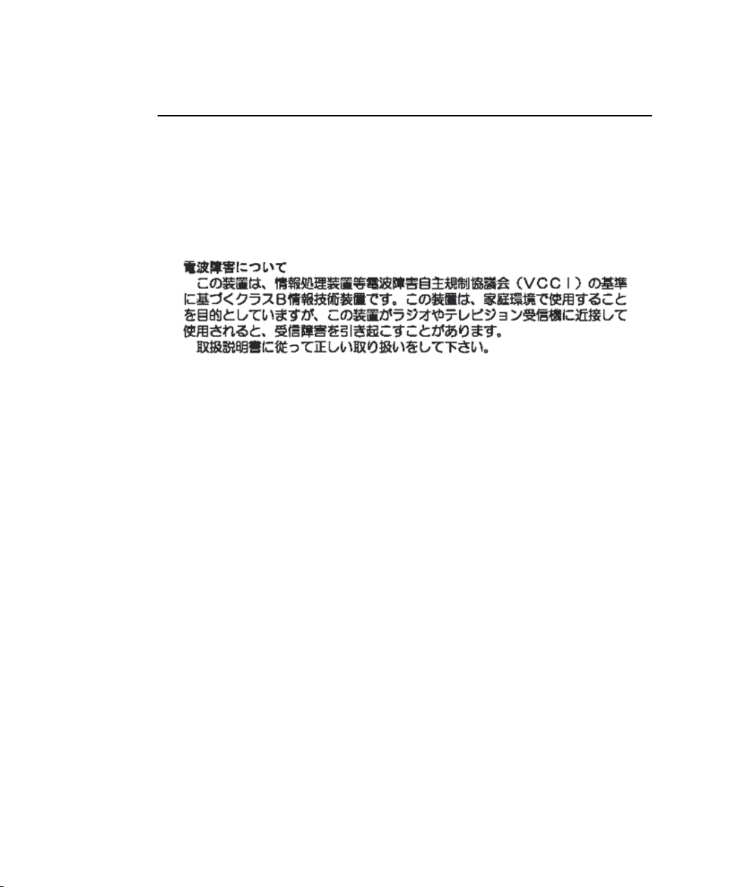
Japan
VCCI Statement
This equipment is in the Class B category (Information Technology Equipment to be
used in a residential area or an adjacent area thereto) and conforms to the standards set
by the Voluntary Control Council for Interference by Information Technology
Equipment aimed at preventing radio interference in such residential areas. When used
near a radio or TV receiver, it may become the cause of radio interference. Read
instructions for correct handling.
Wireless Devices
Low power, Radio LAN type devices (radio frequency (RF) wireless communication
devices), operating in the 2.4 GHz Band, may be present (embedded) in your notebook
system. This section is only applicable if these devices are present. Refer to the system
label to verify the presence of wireless devices.
Wireless devices that may be in your system are only qualified for use in Japan if a
TELEC ID is on the system label.
Operational guidelines for 2.4 GHz band wireless equipment (if equipped)
This equipment uses the 2.4 GHz ISM frequency band. The ISM band is the industrial,
scientific, and medical device band. Devices that might also use this band are
microwave ovens, other LAN devices, amateur radio stations, licensed premises radio
stations, and non-licensed specified low-power radio stations.
xiv Users Manual
Page 15
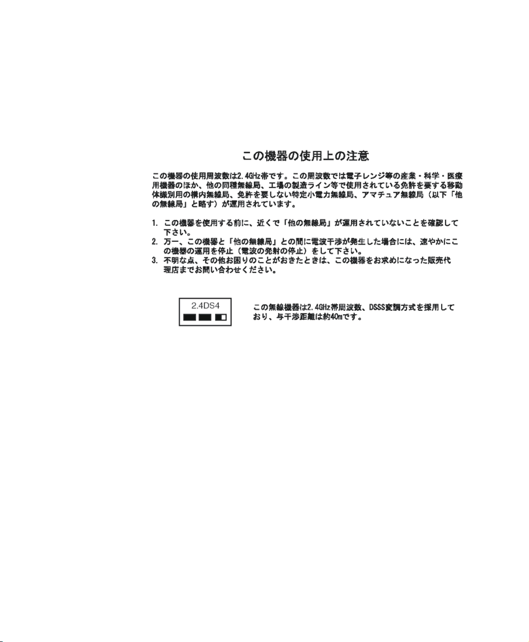
Prior to setting up your device:
1. Make sure that there are no other devices in your area using the same frequency
band.
2. Change the channel, location, or discontinue device use if you are interfering with
any other radio station.
3. Contact manufacturer if you have any problems with this device.
Regulatory Compliance Statements xv
Page 16
Using Your Documentation
Congratulations on your purchase of a notebook computer with the Windows® XP
operating system. Whether you are new to using a portable computer or are an
experienced user, this user’s manual can help you get the most from your computer.
Manual Documentation Conventions
Information Icons
Three icons and their associated messages appear in this manual. The information
icons are placed before the step/information they apply to:
Warning:
Indicates the possibility of personal injury.
Caution:
Warns you of possible damage to equipment or data.
Note:
Informs you of special circumstances.
Technical Information:
Informs you of special requirements or limitations for use of item(s).
Keyboard Conventions
Keys that you need to press to perform certain functions are displayed in the manual in
brackets. For example:
<Ctrl> indicates the control key (Ctrl on the keyboard).
If you need to press two keys at the same time, the key names are shown joined by a
plus sign. For example:
<Fn+F8> means that you should press the Fn key and hold it and then press the F8
key.
Using Your Documentation 1
Page 17
CD-ROM Device Naming Convention
In many installation programs you will have to get a program from the CD-ROM
device. The program installation sequence assumes that the CD is drive d:\, however
this is not always the case. The name of the CD-ROM drive is the letter following the
letter assigned to your last HDD. For instance, if you have one HDD with two
partitions, the HDD is drives C: and D: and the CD-ROM drive is then drive E.
Touchpad Conventions
You may be asked to click or double-click on items on the display screen. As a general
note the touchpad actions act much in the same way as a wheel mouse, any differences
are explained fully.
The object that needs to be clicked upon will be displayed in Bold text or shown in a
small figure such as the “Start Button” shown on the right =>.
Table 1. Touchpad Click Conventions
Action Process
Click Depress the touchpad left button and release
Double-click Quickly click the left touchpad button two times
Windows Conventions:
Almost all “Windows” programs will display the name/function of a button or
icon if you place the touchpad pointer on the item you want information about.
Software User Documentation
Your computer is shipped from the factory with several software programs installed.
The software may include its own online or printed documentation. Refer to the
documentation or the Help options in the software for more information.
The figures and illustrations in this manual may not be identical to those on
your system.
General Icon Note:
Some of the Icons used in Windows XP may be placed on the taskbar by
selecting (ex: Place the volume icon in the taskbar) in the properties dialog
box.
2 Users Manual
Page 18
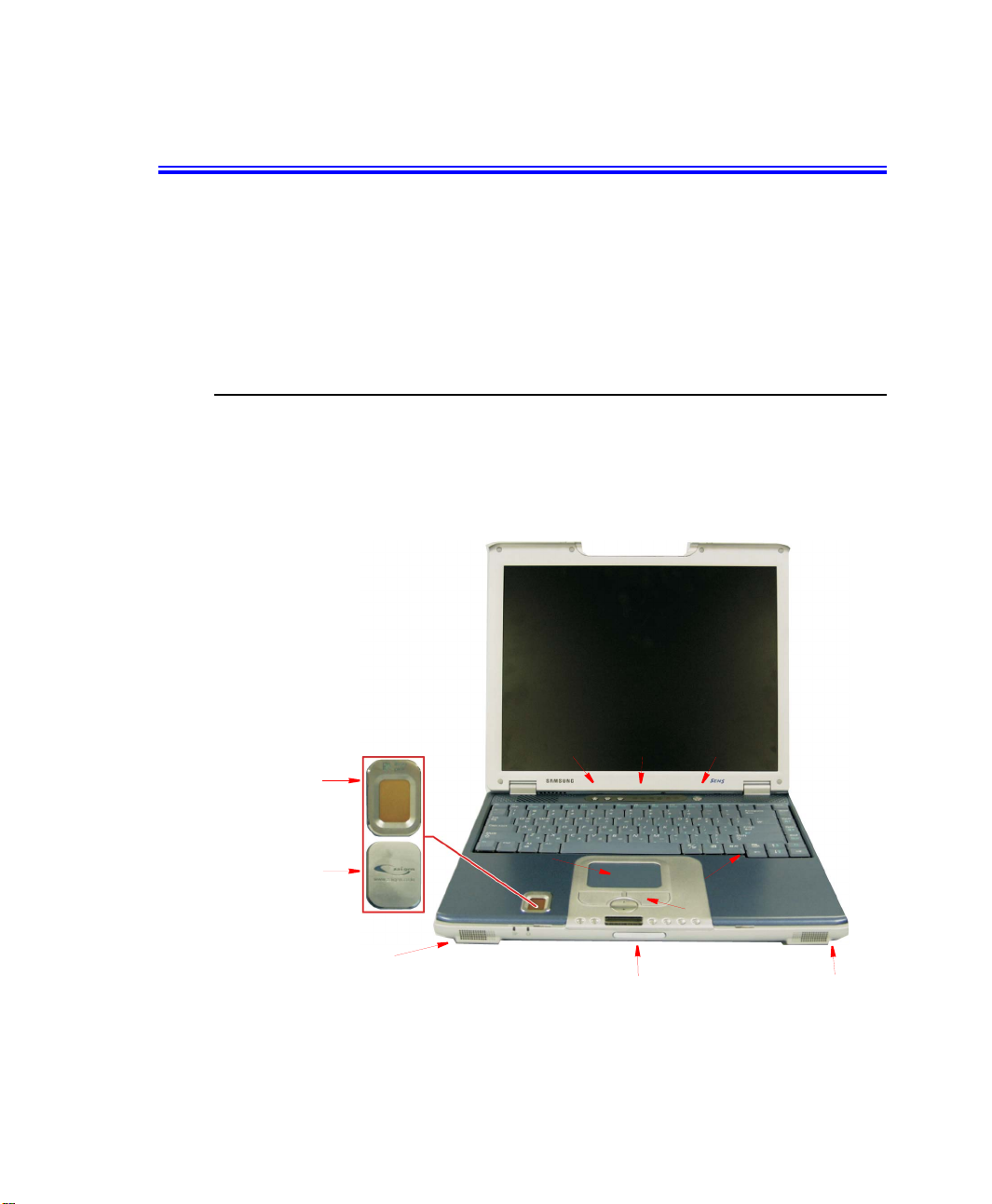
Introducing Your Computer
Your computer is a lightweight portable computer that includes features such as Dolby
Digital & Dolby Home Theater System support, flex-bay, fingerprint recognition
system (factory option), memory stick (factory option), wireless LAN module (factory
option), Bluetooth module (factory option), CD/MP3 player (factory option) to meet
your computing needs at home or on the road.
(Figures may be different depending on options).
Where Everything Is
This section will explain the location of all of the buttons, LEDs and equipment needed
to operate your notebook computer.
Front
NOTE:
The protective cover will replace
the fingerprint sensor if the option
is not ordered.
Fingerprint
Sensor
Protective
Cover
Speaker
Touchpad
Hot Keys
Keyboard
LCD Open Button/Latch
LEDs
Power Button
Internal Microphone
Touchpad Buttons
Speaker
Introducing Your Computer 3
Page 19
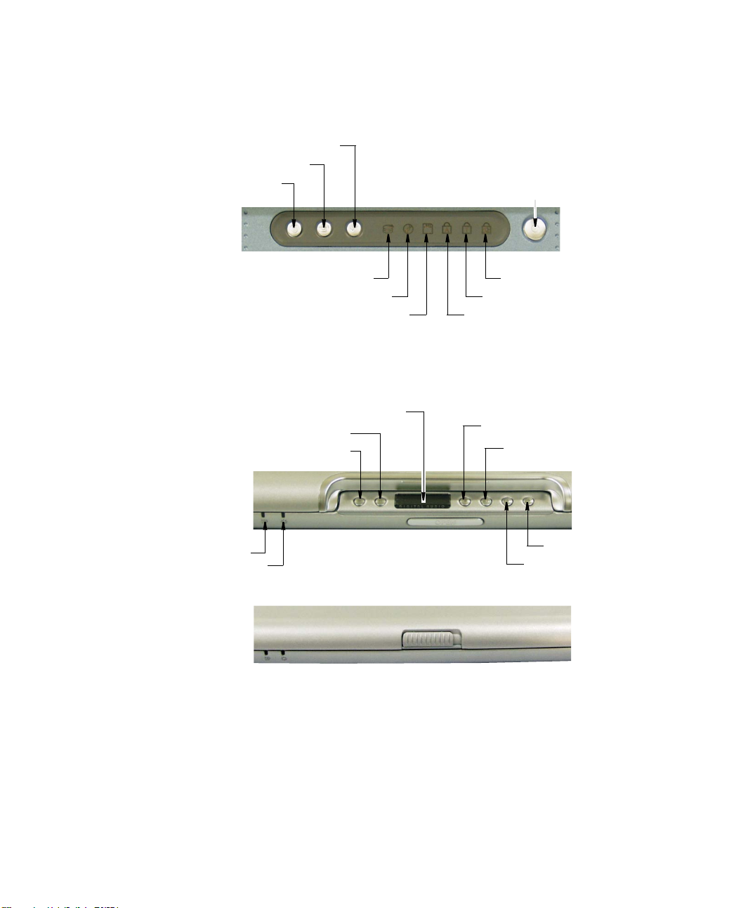
Buttons and LEDs
User Defined Button
E-Mail Button
Internet Button
Power Button
Battery Status LED
Power LED
HDD Access LED
CD Access LED
FDD Access LED
Play/Pause & Track Indicator
Volume Up
Volume Down
MP3/CD Player Option
Without MP3/CD Player Option
Scroll Lock LED
Number Lock LED
Caps Lock LED
Player Off/Stop/Eject
Player On/Play/Pause
Next/Fast Search-Forward
Previous/Fast Search-Reverse
4 Users Manual
Page 20
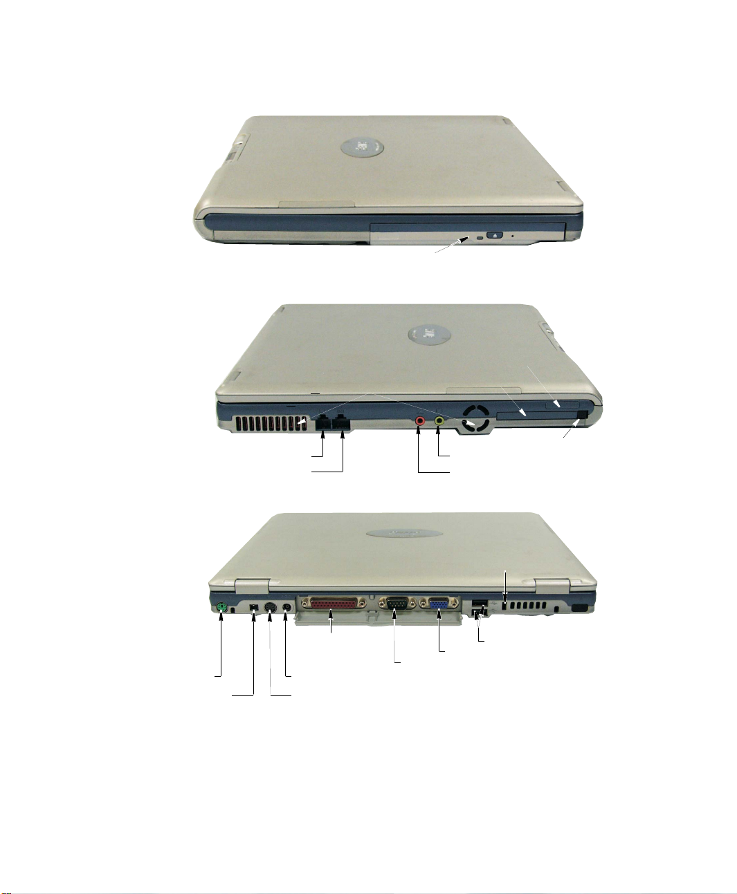
Right Side
Left Side
Back Side
Modem Port
LAN Port
Fan Vent
Flex-Bay
Memory Stick Slot
* Factory Option
PC Card Slot
PC Card Eject Button
Headphone / S/PDIF Jack
Microphone Jack
PS/2 Port
1394 Port
Parallel
Printer Port
DC-In Port
TV-Out Port(S-VHS, option)
Serial Port
Security Lock Port
Fan Vent
USB Ports
External Monitor Port
Introducing Your Computer 5
FIR
* Factory Option
Page 21
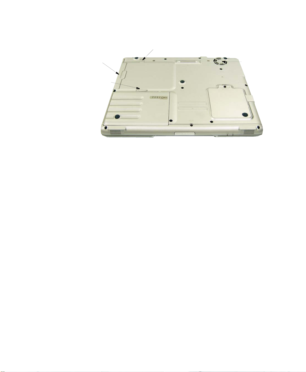
Bottom
Flex-Bay
Compartment
Battery Latch
Battery
Flex-Bay Latch
Port Replicator
Connector
Fan Vent
Memory
Compartment
6 Users Manual
Page 22
Using Your Computer for the First Time
This section gives you detailed information on using your computer for the first time.
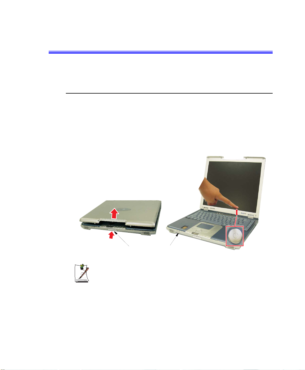
Turning On the Computer
To turn on the computer’s power for the first time:
1. Install the battery and connect the AC adapter according to the Installation Guide.
2. Push the LCD open button and lift up the cover.
Or if you do not have MP3/CD Player option, slide the LCD open latch to the right
and lift up the cover.
3. Press and then release the power button.
The power LED is on when the computer’s power is on.
LCD Open Button/Latch
Initial Computer Startup:
The first time you start your computer you will see the operating system
registration screens. Simply read each screen and follow the simple directions.
You must complete this process in order to use your computer.
Power LED
Using Your Computer for the First Time 7
Power Button
Page 23
Turning Off Your Computer
Prior to shutting down your computer, ensure all of your data and current work are
saved. The system will ask if you wish to save any unsaved work. Saving your work
first will speed the shutdown process.
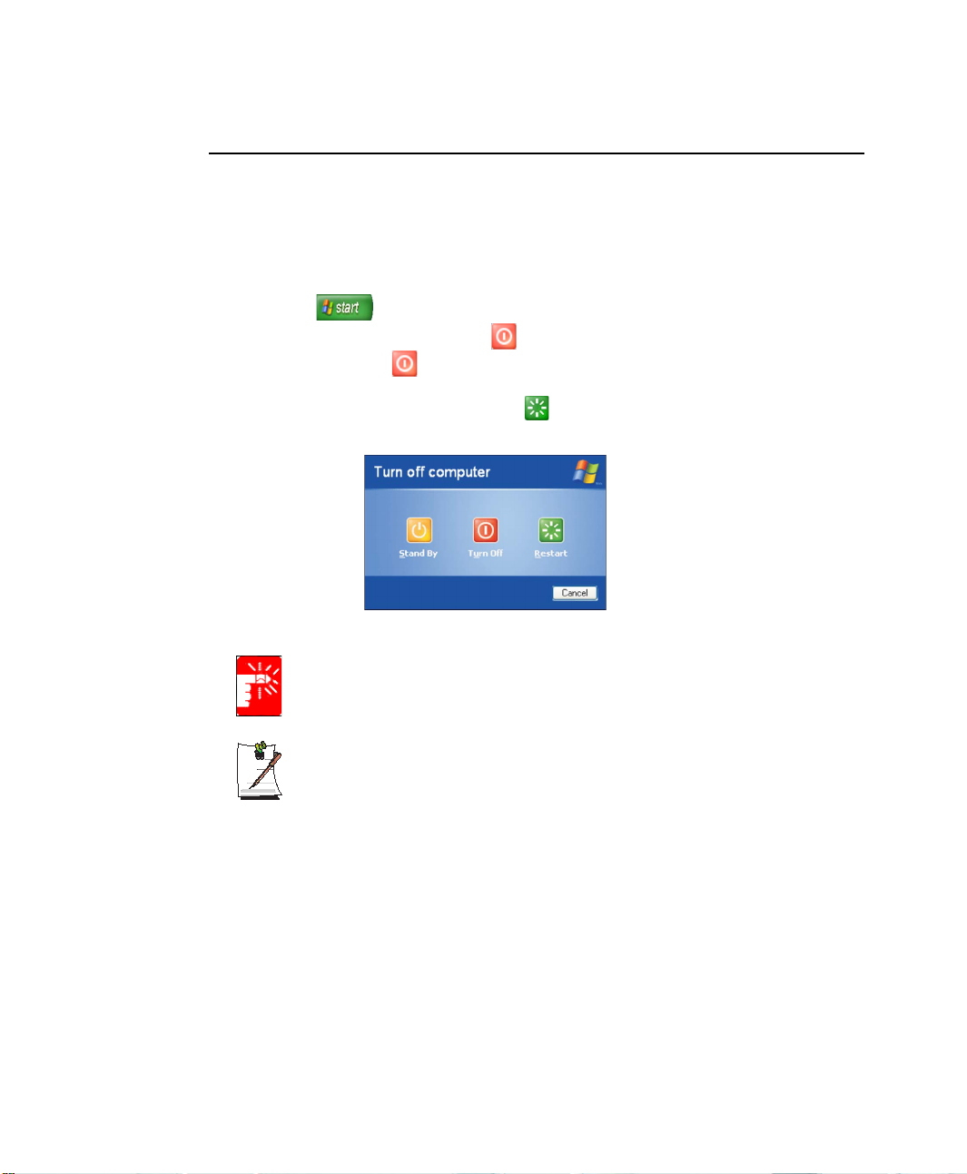
To turn off the computer, complete the following steps:
1. Click on the taskbar.
2. Click Shut Down Computer to display the shutdown popup window.
3. Click Turn Off to complete the shutdown sequence.
If you need to restart your computer after software (re)installation or because it is
not responding, select the Restart option.
Power Off:
If the system is not turned off, then press and hold the power button for over 4
seconds. See ”Using Power Management Options” on page 69.
You can also perform a soft boot by saving your files and pressing
<Ctrl+Alt+Del> to pop-up the “Windows Task Manager” window.
Click Shut Down > Restart.
You can perform a cold boot by pressing the power button for more than 4 seconds to
turn the computer off, waiting more than five seconds, and then pressing the power
button to turn the computer on. The system may perform some extra checks during the
restart.
8 Users Manual
Power Button Functions:
The power button has several functions other than just turning on and off your
computer, see “Using Power Management Options” on page 69.
Page 24

Tips for Using Your Computer
The following information helps you avoid potential problems as you use your
computer:
Do not try to disassemble your computer. Opening the system chassis voids
your warranty. Only an authorised manufacturer service center can replace or
add any parts inside the chassis.
• Follow all the instructions and cautions in your computer user documentation.
• The LCD has a polarized surface and can be damaged easily. To prevent
damage, avoid touching the screen.
• Use only approved AC adapters, auto adapters, memory modules and other
options.
• Because a notebook computer is small and has restricted air flow around
components, it is more likely to overheat than a desktop computer. A fan inside
your computer runs when needed to help eliminate heat. Make sure the fan vent
on the left side of your computer is not blocked when you use the computer.
Occasionally check the vents and remove any accumulated dust on the outside.
• Avoid using or storing the computer in extremely hot or cold areas, such as a
car on a hot day. Keep the computer away from heaters and out of direct
sunlight. Exposure to excessive heat may damage computer components. If you
have left your computer in a hot place, let it cool down slowly to room
temperature (with the LCD panel open) before using it.
• Do not remove the memory-module compartment door, or try to install a
memory module when the computer is on. (For information on installing
memory modules, see “Installing a Memory Module” on page 81.)
• Set up your computer work area to avoid physical strain. Sit with your back
straight and supported by your chair. Adjust your chair or work table so that
your arms and wrists can remain in a relaxed position, parallel with the floor.
Avoid bending or twisting your wrists as you work. Your hands should “float”
slightly above the keyboard. Refer to a book on office ergonomics for more
information on setting up your work area.
• Take frequent breaks from working at the computer to rest your eyes and
stretch your muscles.
• Remember to save your data files frequently and to make backup copies of your
files.
Using Your Computer for the First Time 9
Page 25
Travelling with Your Computer
Air Travel
If you are travelling by air, follow these tips:
• Take the computer with you as carry-on luggage. Do not check the computer
with your baggage.
• Allow the computer and disks to go through the X-ray security devices. Do not
hand-carry disks through the walk-through metal detectors, which can cause
loss of data.
• Make sure that the battery is charged or the power cord is easily accessible.
You may be required to turn on the computer for airport security personnel.
• Be prepared to turn off the computer during take off and landing.
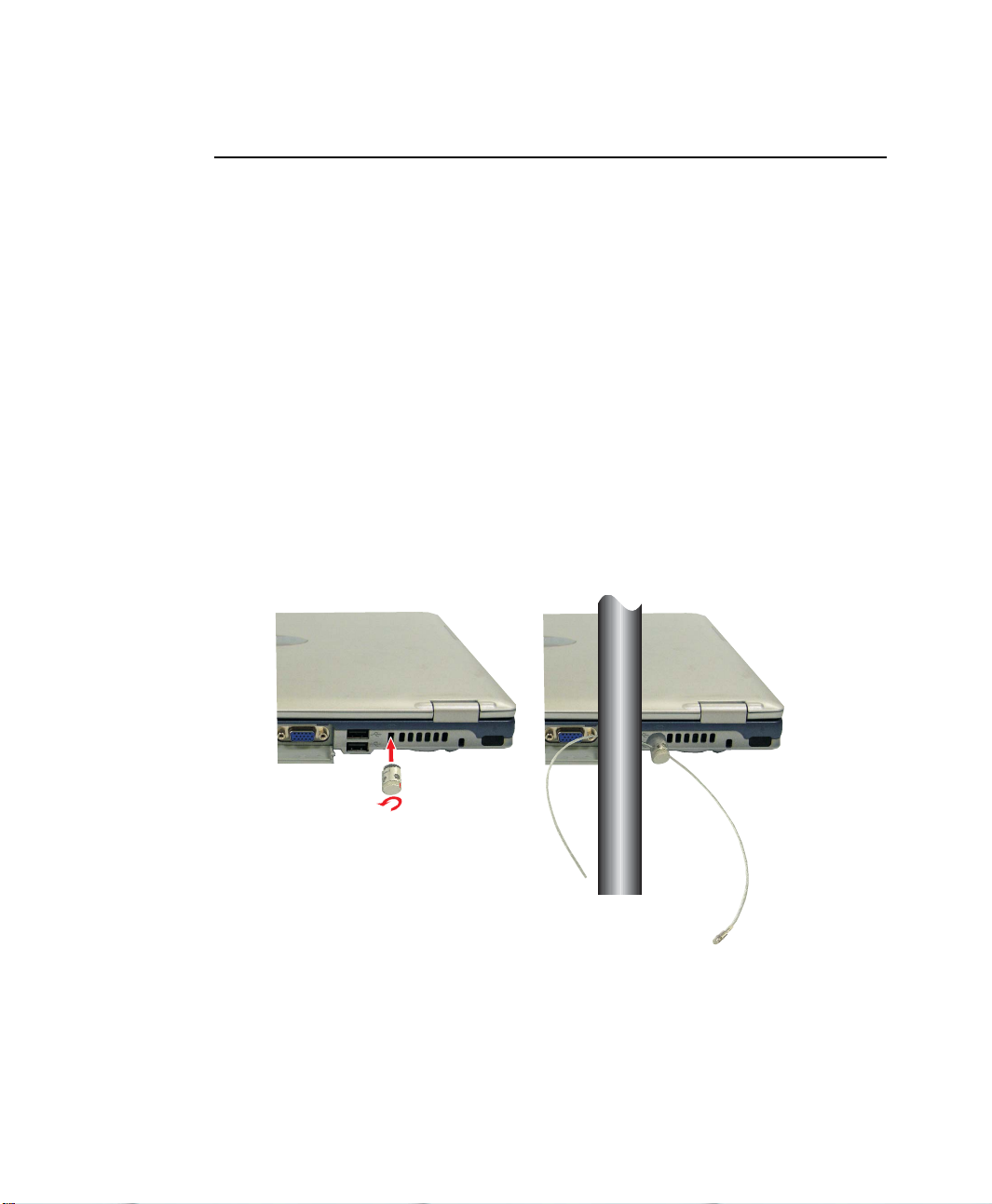
Locking your Computer
As a precaution when you are travelling or using your computer in an unsecured area,
you should keep your computer as safe as possible. An option to do this is the Security
Lock System. Follow the Security Lock System manufacturers instructions for specific
installation and use. The following figure shows generally how to use the lock.
10 Users Manual
Page 26

Handling Spills
Do not spill anything on your computer. The best way to avoid spills is to avoid eating
and drinking around your computer. If you do spill something on your computer, turn
off your computer, unplug it immediately, and do the following:
• If you spill liquid on the keyboard, drain as much of the liquid from the
keyboard as possible. Be careful not to let the liquid drip onto the LCD panel.
Allow the system to dry for several days before trying to use it.
• If you spill liquid on an external keyboard or keypad, unplug it and drain as
much of the liquid as possible. Allow the keyboard to sit at room temperature
for a full day before trying to use it.
Sweet liquids leave a sticky residue that may jam the keyboard despite your
efforts to dry it.
• If you spill liquid on the LCD panel, clean it immediately with a soft cloth and
denatured alcohol or a proprietary LCD screen cleaner. Do not use water,
window cleaner, acetone, aromatic solvent, or dry, rough towels to clean it.
Some liquids damage the polarized LCD screen. If your screen is damaged,
contact your authorized manufacturer’s service center for a replacement.
Storing the Computer for Long Periods
If possible, leave the power cord connected to the computer and an electrical outlet
when the computer is not in use. This extends the life of the battery and keeps the
battery fully charged.
If you will not be using the computer for a long period of time (a month or more), you
should charge the battery until it is completely full. After you have done so, remove the
battery from the unit.
Using Your Computer for the First Time 11
Page 27
Using the Keyboard
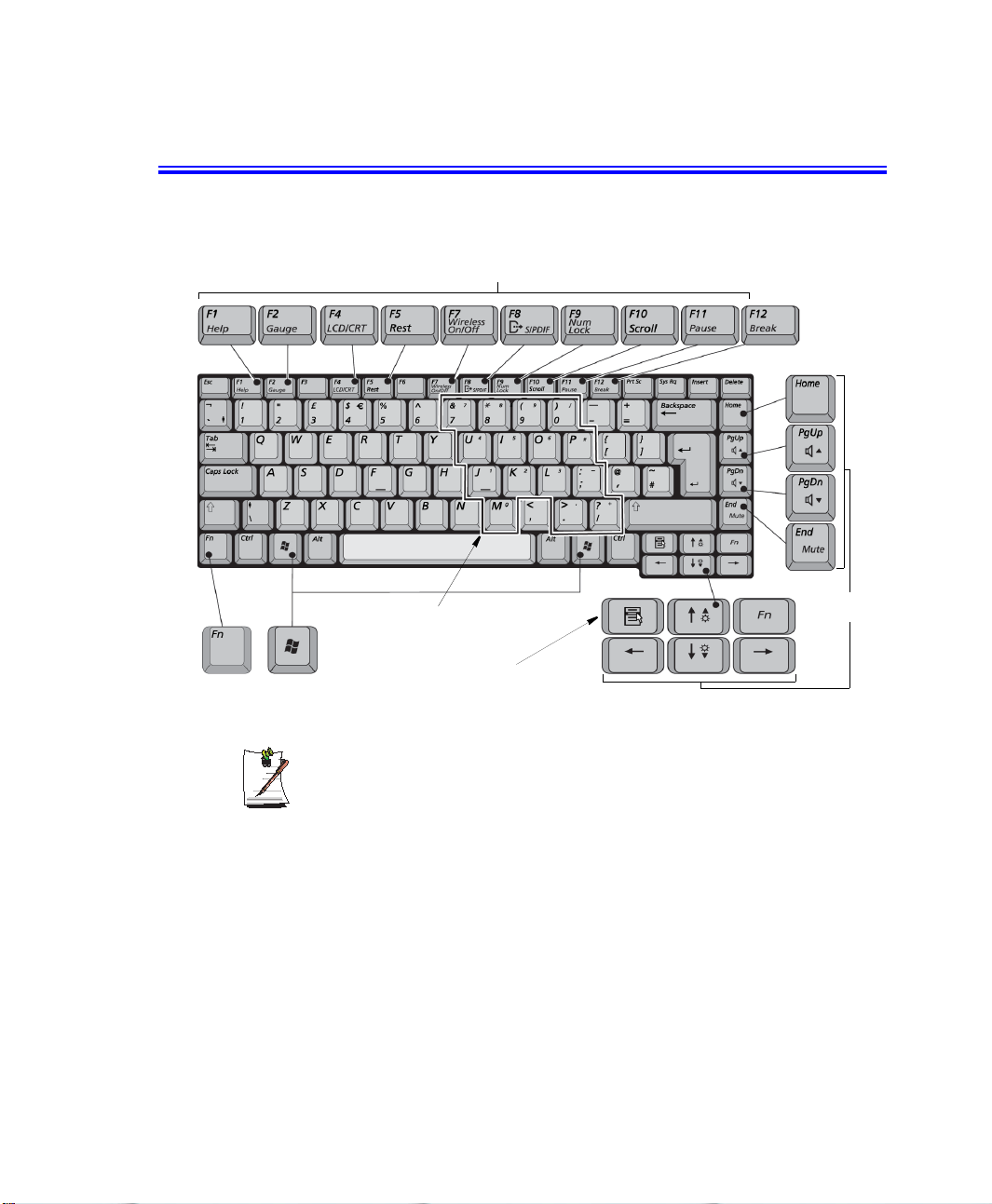
Your computer has an 88/89-key keyboard. By pressing designated key combinations,
you can have access to all the key functions of a full-sized keyboard.
Function & Special Purpose Keys
Embedded Numeric Keypad
Cursor/Screen
Control Keys
Function
Key
The keys on the keyboard can be grouped into the following categories:
12 Users Manual
Windows
Key
Although the layout of the keys on your computer’s keyboard is different from
that on a desktop computer’s keyboard, the keyboard feels like a full-sized
keyboard when you use it.
Application Key
• Full-sized Alphanumeric typewriter keys are arranged like a standard
typewriter keyboard and are used for text entry. The Windows keys on either
side of the spacebar open Windows menus and perform other special functions.
• Function keys, when pressed together with the <Fn> key, enable special
functions.
• Cursor and Screen control keys move the cursor. They may perform other
functions, depending on your software.
Page 28
To clean the computer keyboard, use slightly damp cotton swabs. Scrub the keys and
the surface around the keys.
Do not allow liquid to drip into the keyboard or you may damage the keyboard.
Using the Numeric Keypad
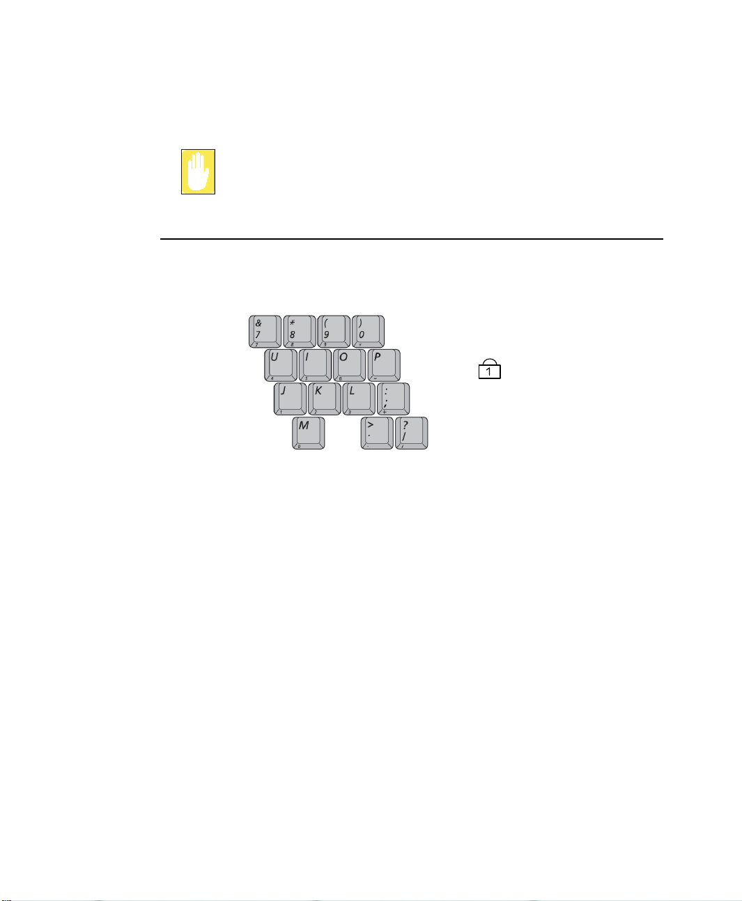
Your keyboard includes a numeric keypad, which is a group of keys that you can set to
type numbers and mathematical symbols, such as the plus sign. A number or symbol
on the left corner of each keypad key shows its numeric function.
Num Lock LED
Press <Fn+F9> to turn on the embedded numeric keypad. The numeric functions of
the keypad are enabled and the Num Lock LED turns on.
While the numeric functions are enabled, you can temporarily return a key to its normal
function by pressing the key and the <Fn> key. For example, to type the letter m, press
<Fn+M>, this operation displays the letter m.
To turn the numeric keypad off, press <Fn+F9> again. The Num Lock LED turns off.
Using the Keyboard 13
Page 29

Using Special Function Keys
The function key activates special functions when it is pressed in combination with
another keys. Table 2 shows the special key combinations.
Table 2. Description of Special Function Key Combinations
<Fn> Key
Combinations
<Fn+F2> F2
<Fn+F4> F4
<Fn+F5> F5
<Fn+F7> F7
<Fn+F8> F8
<Fn+F9> F9
<Fn+F10> F10
<Fn+F11> F11
<Fn+F12> F12
<Fn+PgUp> PgUp: Volume up: Increases the audio volume.
<Fn+PgDn> PgDn Volume down: Decreases the audio volume.
<Fn+End> End
<Fn+Up Arrow> Brightness Up: Increases the LCD brightness.
<Fn+Down Arrow> Brightness Down: Decreases the LCD brightness.
Key
Name
Gauge
LCD/CRT
Rest:
Wireless
On/Off
S/PDIF
Num Lock
Scroll
Pause
Break
Mute:
Key Function
Gauge Displays the gauge showing the power source, battery
LCD/CRT: Switches the display between the LCD, the external
Rest: Puts the computer into Suspend mode. To resume normal
Wireless On/Off: Toggles the Wireless LAN function On/Off
S/PDIF: Toggles the S/PDIF function On/Off.
Num Lock: Activates the numeric keypad.
Scroll: In some applications, sets the cursor-control keys to scroll
Pause: Stops a program operation in DOS mode.
Break: Exits a program in DOS mode.
Mute: Mutes the audio.
level, wireless on/off, and S/PDIF on/off. The gauge closes
in a few seconds, or you can press <Esc> to close the
gauge.
monitor, and simultaneous display on both the LCD and
the external monitor.
operation from rest, press the power button. (See ”Using
Power Management Options” on page 69 for more
information about the rest mode.)
the page up or down while the cursor position does not
change. Pressing key combination again turns off the
scrolling function.
14 Users Manual
When you press a function key combination, the system sound may be
temporarily muted.
Page 30
Hot Keys
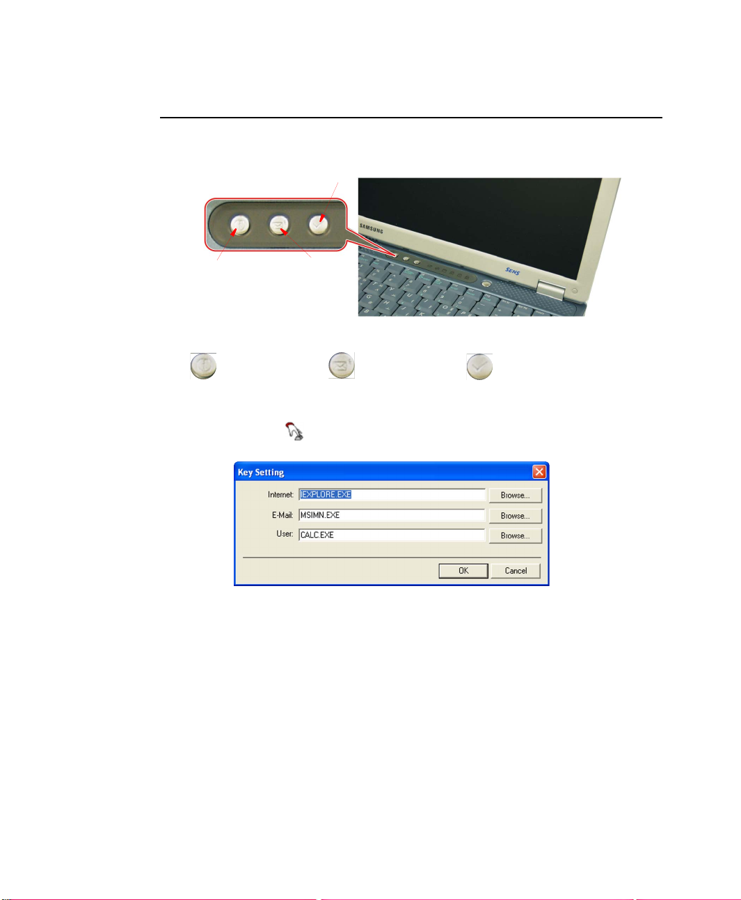
You may program the three buttons to the left of the power button to start any program
you have installed on your computer.
User Defined Button
Internet Button E-Mail Button
The default settings for these buttons are:
Internet Explorer Outlook Express Windows Calculator
To reprogram the hot keys, follow the steps below:
1. Double-click icon on the Windows taskbar, the Key Setting window is
displayed.
2. Select a button and click the Browse button to locate the program you wish to
assign to the button.
3. Click on your program choice to select it. Click Open.
4. Click OK to close window.
Using the Keyboard 15
Page 31
Using the Touchpad
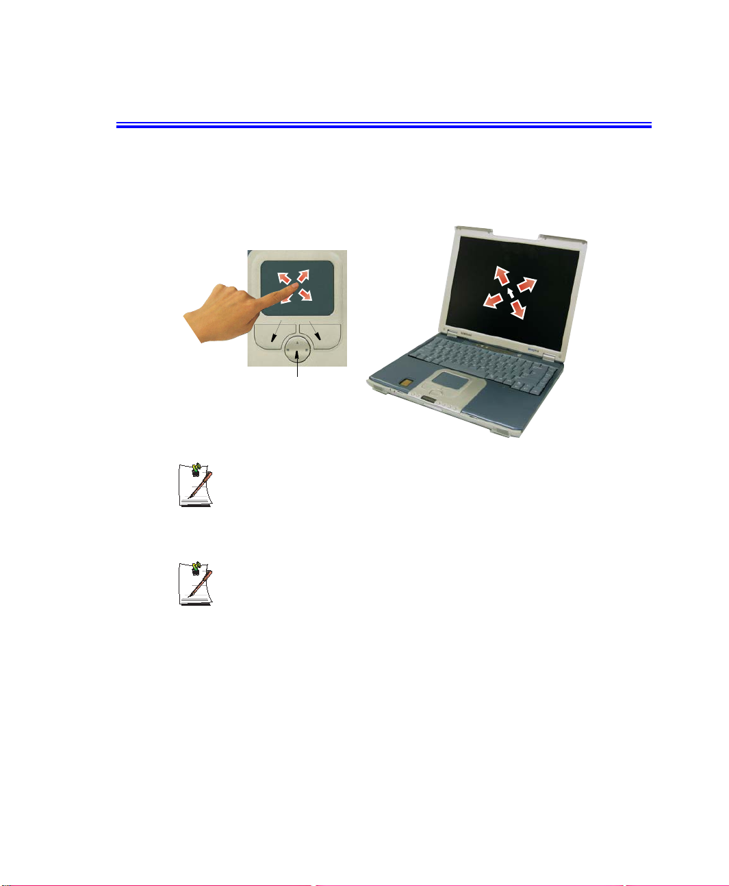
Your computer is equipped with a touchpad, which is an integrated-pointing device
that is used to perform standard mouse functions. The touchpad is an advanced and
reliable pointing device that works with a touch of your finger.
Touchpad
Touchpad Buttons
Scroll Button
Four (4) Direction Scroll Button (Default is a 2 Direction Button)
If you have purchased your computer without the CD/MP3 player option, your
computer will have a four (4) direction scroll button. The operation of the scroll
button is explained below.
16 Users Manual
Press on the touchpad gently. The touchpad responds to light pressure.
Page 32
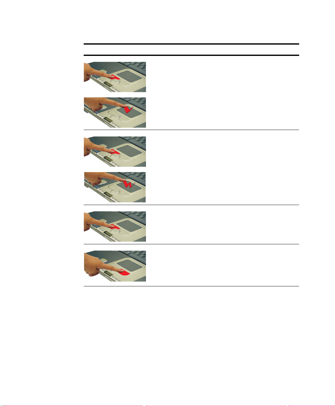
d
Action Process and Comment
Click/Tap
Process
Depress the touchpad left button and release or position the pointer
over the object and quickly tap the touchpad once with your finger.
This action is called clicking.
Comment
This will cause a process to begin or select an object on the screen.
Double-click/Tap
Click-Hold
Right-click
Process
Quickly click the left touchpad button two times or position the pointer
over the object and Quickly tap the touchpad twice with your finger.
This action is called Double-clicking.
Comment
This will cause a process to begin or open a file folder.
Process
Depress the left touchpad button and do not release.
Comment
This is used to move/drag objects to new locations. See ”Drag (Move)”
on page 19.
Process
Position the pointer over the object. Quickly press and release the right
button once.
This action is called Right-clicking.
Comment
This is usually used to obtain information about an object or access a
short cut menu.
Using the Touchpad 17
Page 33
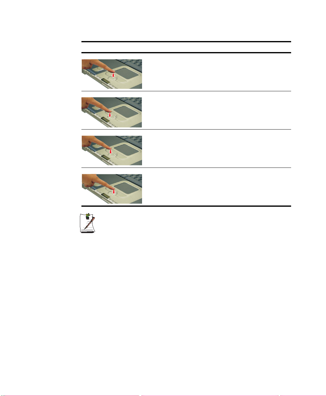
Action Process and Comment
Scroll Up
Scroll Down
Process
Place your finger on the top half of the button to scroll up the current
window.
Comment
Moves the current window down.
Process
Place your finger on the bottom half of the button to scroll up the current
window.
Comment
Moves the current window up.
Scroll Left
Scroll Right
Process
Place your finger on the left half of the button to scroll left in the current
window.
Comment
Moves the current window right.
Process
Place your finger on the right half of the button to scroll right in the
current window.
Comment
Moves the current window left.
PS/2 Mouse Menu:
You may change the setup in System Setup > Advanced Menu.
Disabled : Prevents any installed PS/2 mouse from functioning, but frees
up IRQ12.
Enabled : Forces the PS/2 mouse port to be enabled regardless if there is
a mouse present.
Auto Detect : Enables the PS/2 mouse only if present.
18 Users Manual
Page 34
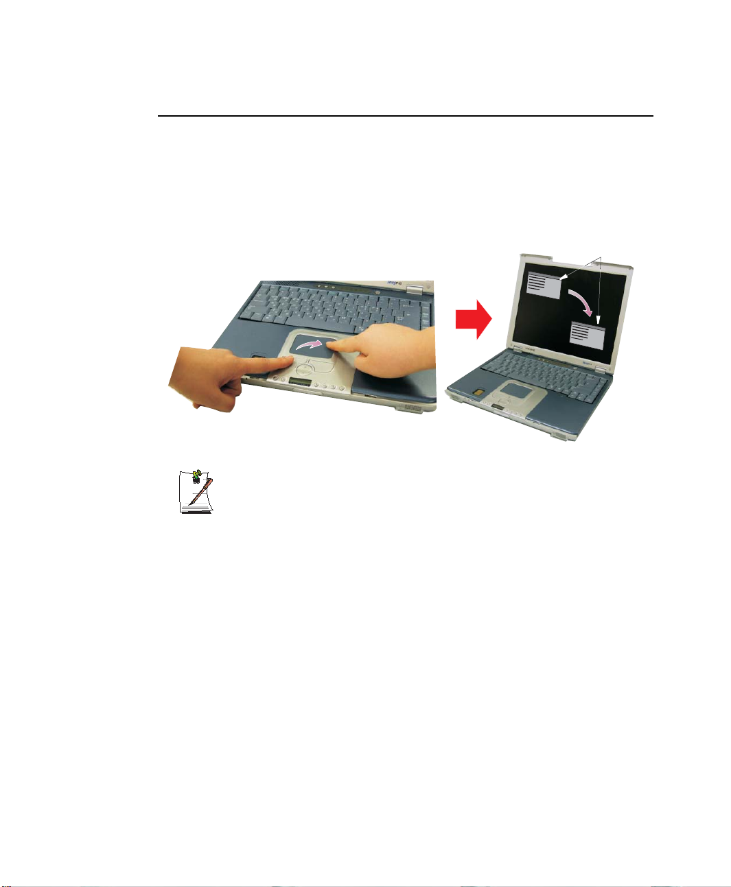
Drag (Move)
To move a window on the desktop, complete the following:
1. Click the window title bar of the window which you want to drag using the
touchpad.
2. Press the left touchpad button and hold it.
3. Drag the window using the touchpad.
2
1
Windows Title Bar
1 Click the Window
Title Bar and Hold
Area or Multiple item selection:
The drag function may be used to select an area or multiple items in an area
by clicking in one area and then dragging to create a selection window. The
items inside the window will be selected.
2 Drag your finger to
move the window
Using the Touchpad 19
Page 35
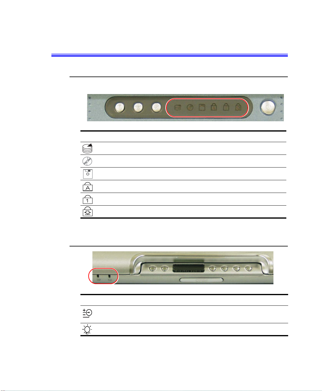
Reading the System Status Lights
System Top
System Status lights show the status of computer functions.
LED Name Function
HDD Access Blinking Green - HDD is being accessed.
CD Access Blinking Green - CD is being accessed.
FDD Access Blinking Green - FDD is being accessed.
System Bottom
LED Name Function
20 Users Manual
Caps Lock Changes all alpha or letter input into capital letters.
Num Lock Changes a portion of the keyboard to a numeric keypad.
Scroll Lock Scroll lock in certain software.
Battery Status Green - No battery pack installed/battery fully charged.
Power Green - System power on.
No changes occur to numeric and special keys.
See ”Using the Numeric Keypad” on page 13.
Amber - Charging.
Blinking - Bad Battery
Blinking - Standby mode.
Page 36
Connecting to the Internet
This section explains how to connect you to the internet. For details on how to establish
the connection contact the Internet Service Provider (ISP) or system administrator
(SysAdmin).
Connecting to the Internet Using a Modem
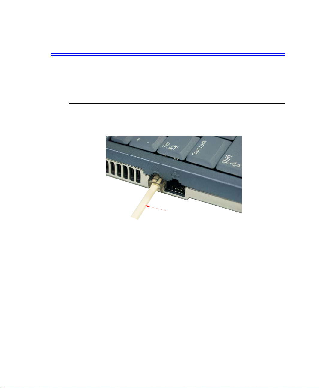
Install the Modem cable by simply plugging the cable into the modem slot as shown in
the figure below.
Modem Cable
(Minimum 26 AWG)
1. Contact your Internet Service Provider to obtain information or CD required to
make the connection in your area.
2. After the cable is connected create a “Dialup” connection by clicking
Start > Control Panel > Network and Internet Connections.
3. Click Set up or change your Internet connection > Setup to start the connection
wizard.
4. Follow the instructions in provided in the Make New Connection wizard.
Connecting to the Internet 21
Page 37
Precautions Before Use
Country Selection
Country Selection:
Because your computer is very mobile you must ensure you select the
country you are calling from is selected correctly, otherwise you may
experience connection problems.
To change the country selection proceed as follows:
1. Click Start > Control Panel > Network and Internet Connections.
2. Click Phone and Modem Options.
3. Click on the connection you wish to edit in the Locations: box.
4. Click Edit in the Dialing Rules Tab
5. Select the Country/region you are calling from in the General tab.
6. Click OK to close the “Edit Locations” box.
7. Click OK to close “Phone and Modem Options” box.
Digital Phone Lines:
If you connect the modem to a digital phone line (such as a company
4-wire system), the modem may be damaged.
DOS support
• Windows XP: Does not support pure DOS mode and the modem does not
support a DOS box in Windows. So you cannot use a
communication application which runs under DOS.
Using the Modem on a PBX system
If you use a Windows Communication Program:
1. Click Start > Control Panel > Network and Internet Connections.
2. Click Phone and Modem Options.
3. Click Properties in the Modems tab section.
4. Check off “Wait for dial tone before dialing” check box in the Modem tab section.
5. Click OK to close the dialog box.
6. Click OK to close “Modem Properties” dialog box.
22 Users Manual
Page 38
If you use a simple terminal program (i.e. hyper terminal):
Type the “ATX3&W” or “ATX3” command as an initialization command.
MODEM Notes:
1. In order to use the 56K feature, be sure to check if the standards supported
by the on-line service provider and the modem are identical.
2. If you use a PBX phone system, you can not connect using the 56K mode.
3. Internationally connected calls will be limited to 33.6K (Max.)
Configuring Network Environment Settings for Wired LAN
You may connect to the network using a LAN cable.
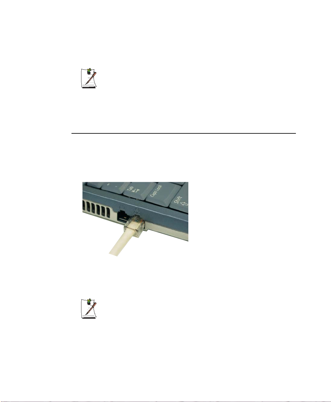
Cable Connection
Install the LAN cable by simply plugging the cable into the slot in the left side of the
computer.
Your computer’s LAN adapter is ready to use for most situations, however if your
system does not have a DHCP server or you wish to personally configure your LAN
connection, proceed as outlined in “Configuring Network Environment” below.
Network Protocols:
You may need to consult your SysAdmin if their network protocols and settings
are required for your LAN environment.
Connecting to the Internet 23
Page 39
Configuring Network Environment
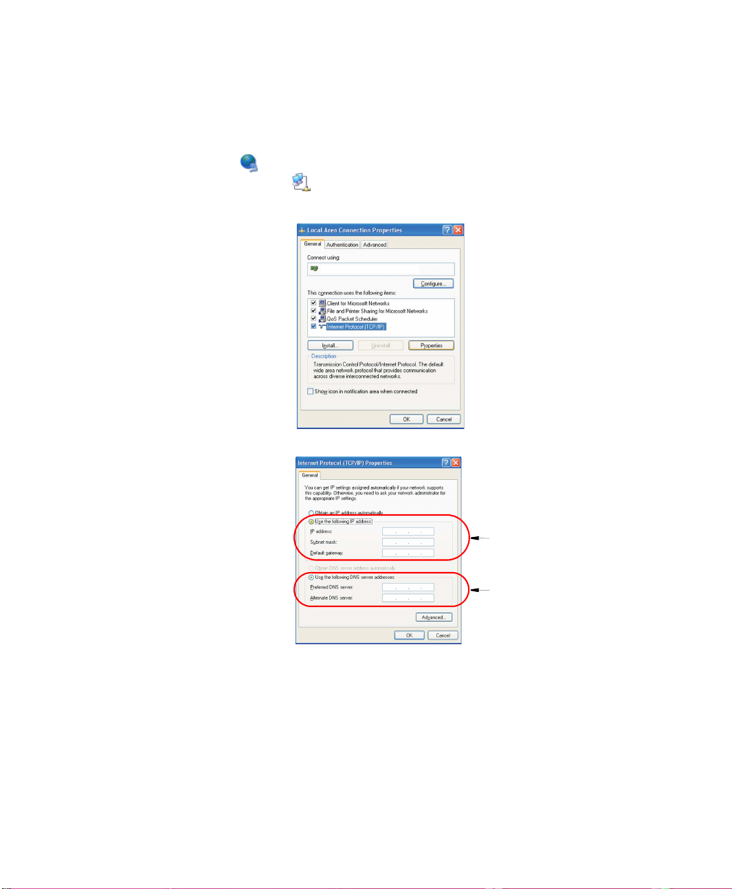
Configure the Network Adapter as follows:
1. Click Start > Control Panel > Network and Internet Connections
2. Click icon (Network Connections).
3. Right-click the icon (Local Area Network) then click Properties button.
4. Select Internet Protocol (TCP/IP) in the “This connection uses the following
items:” box.
Intel(R) Pro/100 VE Network Connection
5. Click Properties. The TCP/IP Properties window opens.
6. Click “Use the following IP address” in the General tab
7. In the “Use the following IP address” box, enter your IP address, subnet mask
8. In the “Use the following DNS server addresses” box, Enter your Preferred DNS
9. Click OK when you finish the TCP/IP set-up.
24 Users Manual
Step 7
Step 8
and Default Gateway.
server and Alternate DNS server.
Page 40
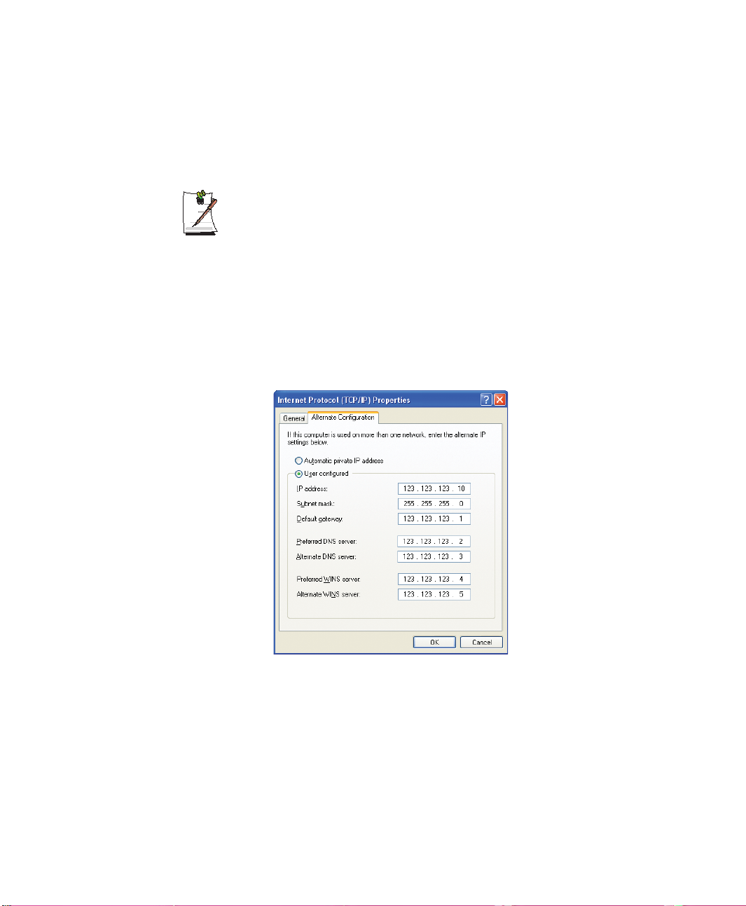
Using Both DHCP and Static IP Simultaneously
When you are alternatively using networks with either DHCP or static IP addressing,
you can use both of the network connections without reconfiguring using alternative
settings that enable simultaneous configurations of DHCP and static IP.
This function is provided only when your operating system is Windows XP.
1. Click Start > Control Panel > Network and Internet Connections > Network
Connections > Local Area Connection, press the right button of the touchpad,
and then select Properties.
2. Select the Internet Protocol (TCP/IP) item, and then click Properties.
3. In the Alternate Configuration tab, click User configured, and then enter the
appropriate values for the following: IP address, Subnet mask, Default gateway,
Preferred and alternate DNS server, and Preferred and alternate WINS server.
4. When the configuration has been completed, click OK.
Now you can connect to both networks using DHCP and static IP respectively.
Connecting to the Internet 25
Page 41

Configuring Network Environment Settings for Wireless LAN
A wireless network (Wireless LAN) environment is a network environment that
enables communication between multiple computers at home or a small-size office
through wireless LAN devices.
Using the wireless network connections between the systems, you can use normal
network functions such as sharing of files, folders and printers. Using computer-tocomputer network (ad hoc) connections, you can access the Internet through a
computer connected directly to the Internet even if your computer is not directly
connected to the Internet. For details, see “Using Network Services” on page 35.
The information provided in this section only applies to models equipped with
an optional wireless LAN device.
Wireless network connections can be classified into two categories.
1) Access Point
You can connect to an AP to use the network. This is possible only in an environment
equipped with an AP. For details, see “Connecting to an Access Point (AP)” on page
27.
What is an Access Point (AP)?
An AP is a network device that bridges wired and wireless LANs, and
corresponds to a wireless hub in a wired network. You can connect multiple
wireless LAN installed computers to an AP.
2) Computer-to-computer (peer-to-peer or ad hoc)
This is also called a peer-to-peer or ad hoc network.
In computer-to-computer wireless networks, you can wirelessly connect 2 or more
computers that have wireless LAN modules. Using computer-to-computer wireless
networks, you can access the Internet through a computer that is connected to the
Internet even if your computer is not directly connected to the Internet. For details, see
“Connecting to computer-to-computer networks (peer-to-peer or ad hoc)” on page 28.
26 Users Manual
Page 42
To turn wireless function on/off
Press <Fn+F7> keys to turn wireless function on/off. Press <Fn+F2/Gauge>
keys to see if the wireless function is turned on( ) or off( ).
Connecting to an Access Point (AP)
This section describes how to connect to an AP. You can use the network when you are
connected to an AP.
In this section, the configuration procedures are described for Windows XP
installed computers. For information on the configuration procedures for other
operating systems, see “Using Networks in Other Operating Systems” on page
33. Please ask your network administrator about detailed configuration
information such as the network key (encryption key).
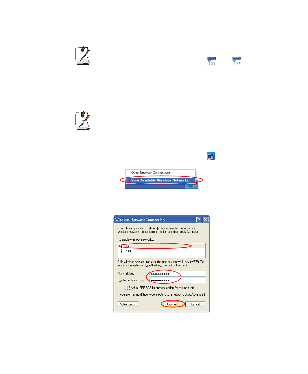
1. Right-click on the Wireless Network Connection ( ) icon on the taskbar, and
select View Available Wireless Networks.
2. Select your desired AP (e.g. Test) to connect, and enter the encryption key for the
AP in the Network key field, and click Connect.
Connecting to the Internet 27
Page 43
If the network key is not configured for the desired AP, select 'Allow me to
connect to the selected wireless network, even though it is not secure’.
Now you are connected to the AP, and you can access the network.
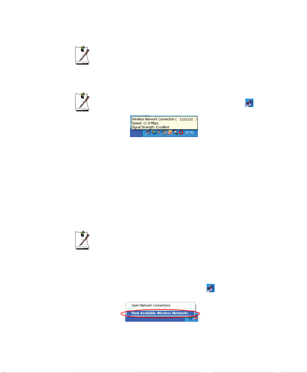
Checking the connection status
Move the mouse pointer over the Wireless Network Connection ( ) icon on
the taskbar, and the connection status is displayed.
Connecting to computer-to-computer networks (peer-to-peer or
ad hoc)
In computer-to-computer wireless networks, you can wirelessly connect 2 or more
computers that have wireless LAN modules.
You can connect by completing the following steps:
• Step 1. Set up a computer-to-computer network on a computer.
• Step 2. Connect to the configured computer from other computers.
Step 1. Setting up a computer-to-computer network
1. Right-click on the Wireless Network Connection ( ) icon on the taskbar, and
28 Users Manual
In this section, the configuration procedures are described for Windows XP
installed computers. For information on the configuration procedures for other
operating systems, see “Using Networks in Other Operating Systems” on page
33.
select View Available Wireless Networks.
Page 44
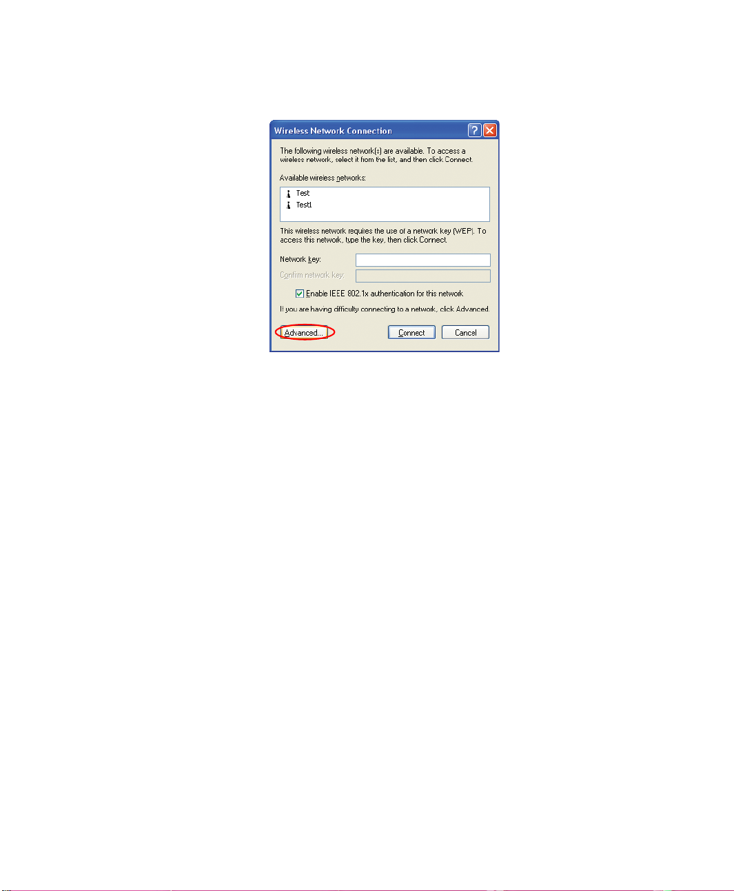
2. Click Advanced.
3. On the Wireless Network tab, click Advanced.
4. Clear 'Automatically connect to non-default network' check box, if it is selected.
Select 'Computer-to-computer (ad hoc) networks only', and click Close.
5. In the Wireless Networks tab, click Add.
Connecting to the Internet 29
Page 45
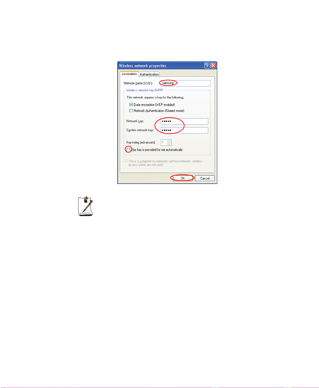
6. Enter the network name (e.g. samsung), and unselect 'The key is provided for me
automatically'. Enter the encryption key in the Network key field, and click OK.
To prevent a network connection from an unauthorized user, it would be better
to configure a network key (encryption key). A network key consists of 5 or 13
alphanumeric characters (e.g. magic), or of 10 or 26 hexadecimal numbers (a
hexadecimal number is represented by numbers '0' to '9' or letters 'a' to 'f').
30 Users Manual
Page 46
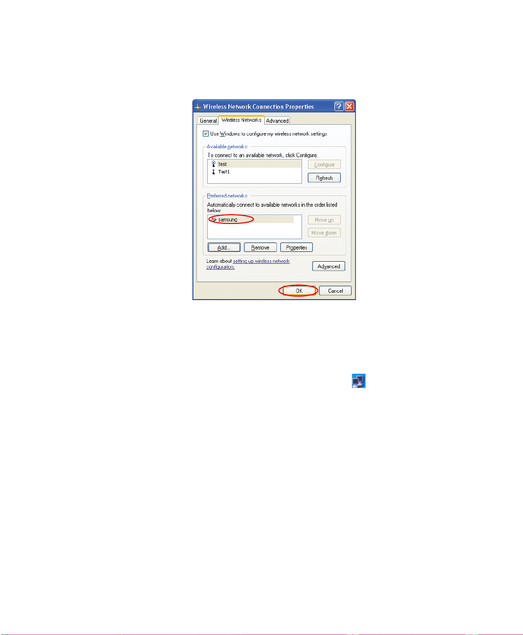
7. Check that the configured network name (e.g. samsung) is in the ’Preferred
networks’ item, and click OK.
Now your wireless network setup has been completed.
Step 2. Connecting to the configured computer
1. Right-click on the Wireless Network Connection ( ) icon on the taskbar, and
select View Available Wireless Networks.
2. Select the wireless network name (e.g. samsung) specified in ”Connecting to
computer-to-computer networks (peer-to-peer or ad hoc)” on page 28, enter the
encryption key in the Network key field, and then click Connect.
Connecting to the Internet 31
Page 47
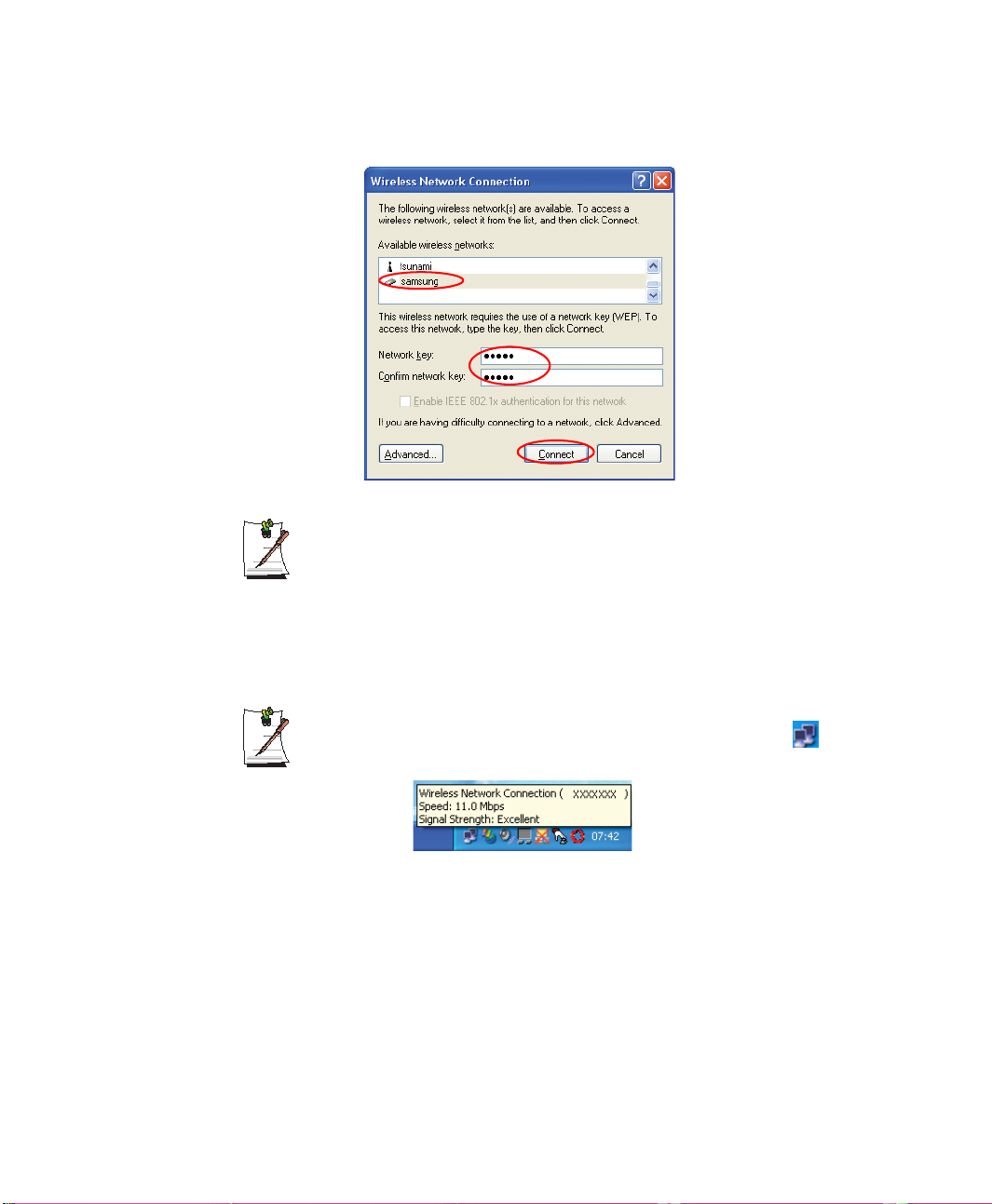
If the network key is not configured in ”Connecting to computer-to-computer
networks (peer-to-peer or ad hoc)” on page 28, select 'Allow me to connect to
the selected wireless network, even though it is not secure'.
The two computers are connected and are able to communicate with each other. When
the computers are connected, the 'Wireless Network Connection' message is displayed
for a short time over the Wireless Network Connection icon of the two computers.
Checking the connection status
Move the mouse pointer over the Wireless Network Connection ( ) icon on
the taskbar, and the connection status is displayed.
32 Users Manual
Page 48
Using Networks in Other Operating Systems
This section describes the wireless network configuration procedures for operating
systems other than Windows XP.
You can connect to the network by completing the following steps.
• Step 1. Install the 'Wireless Client Manager' program.
• Step 2. Set up a network in the target computer.
To connect two computers with a computer-to-computer (peer-to-peer)
network, the following procedures have to be completed for both computers.
Step 1. Installing the wireless client administrator program.
Install the 'Wireless Client Manager' program from the system software CD in the
target computers.
(D:\Application\WirelessLan\Setup.exe)
Step 2. Setting up the network.
1. Click on the Wireless LAN Program ( ) icon on the taskbar. (Or click Start >
All Programs > Samsung Wireless LAN > Client Manager.)
2. Click Actions > Add/Edit Configuration Profile.
3. Click Add.
4. Select the desired Network Type in the 'Select Profile' window, and enter the
Profile Name. Click Next.
Network Types
- To connect to an AP: Select Access Point
- To configure a computer-to-computer network : Select Peer-to-Peer Group
Do not select 'Act as BaseStation', because this is not supported at present.
Connecting to the Internet 33
Page 49
5. Enter the desired network name (i.e. AP name) in the 'Identify Your Network'
window, and click Next.
If you do not know the network name when you connect to the AP, click the
Scan button, and select the name from the displayed name list.
When configuring a computer-to-computer wireless network, all target
computers have to specify the same network name.
6. If a network key is configured in the AP or computer-to-computer network, select
Enable Data Security in the 'Set Security' window, enter the same network key, and
then click Next.
While setting up a computer-to-computer wireless network, you are
recommended to configure a network key (encryption key) to prevent a
network connection from an unauthorized user. Create a new network key in
the first target computer, and then enter the same key in the other target
computer.
The network key consists of 5 or 13 alphanumeric characters (e.g. magic), or
of 10 or 26 hexadecimal numbers (a hexadecimal number is represented by
numbers '0' to '9' or letters 'a' to 'f').
7. In the 'Power Management' window, click Next.
To maximize performance in the default power configuration, select Off. To
minimize power consumption, select On.
8. In the 'TCP/IP Behavior' window, click Finish.
9. On the 'Add/Edit Configuration Profile' window, click OK to complete the
34 Users Manual
This item does not appear during computer-to-computer wireless network
configuration.
To update and use a new IP whenever selecting the profile that is currently
configured, select the Renew IP Address when selecting this profile item.
wireless network configuration.
Page 50

Using Network Services
While the computer is connected to the network, you can use network services to share
files, folders, and printers. Using computer-to-computer wireless networks, you can
access the Internet through a computer that is connected to the Internet even if your
computer is not directly connected to the Internet.
Network services are provided for the computers that are connected to the
network through wired or wireless network connections. For details, see
“Configuring Network Environment Settings for Wired LAN” on page 23 and
see “Configuring Network Environment Settings for Wireless LAN” on page 26.
Sharing files or folders
This section describes how to share files and folders between computers connected to
the network.
To share files, complete the following procedures:
• Step 1. Configuring the sharing of files and folders on a computer.
• Step 2. Accessing shared files and folders from another computer.
When a file or folder is shared, anyone connected to the network can open and
delete the shared file or folder.
Configure a file sharing network only when the network is secure, and do not
share important data.
Connecting to the Internet 35
Page 51
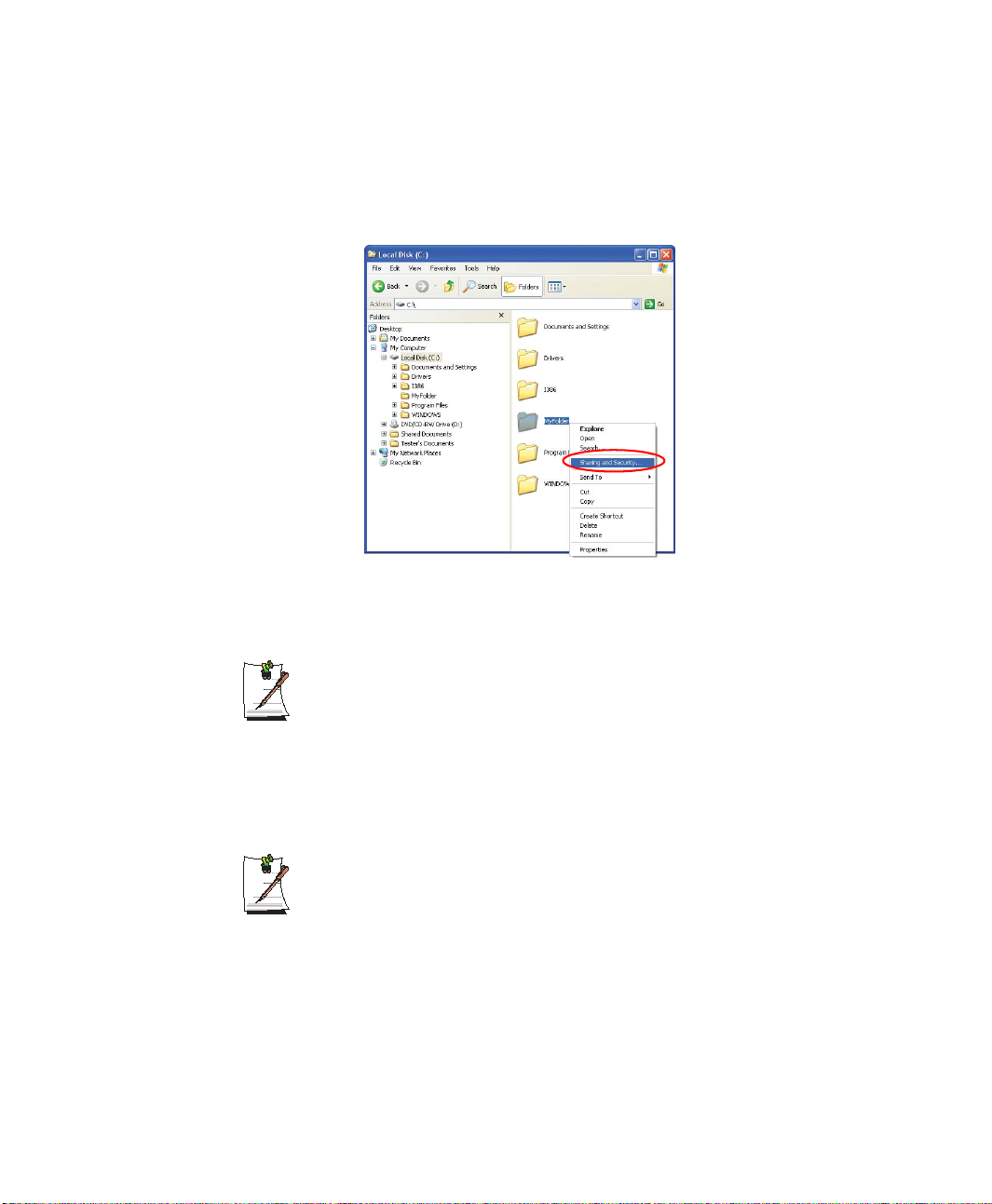
Step 1. Configuring Sharing
1. Right-click the target file or folder to share in My Computer, and select Sharing
and Security.
2. Click 'IF you understand the security risks but want to share files without running
the wizard, click here'.
It has the same security effect as that of the 'Network Setup Wizard'.
This screen does not appear if Internet Sharing Network Wizard has been
installed in the computer-to-computer wireless network environment.
3. Select 'Just enable file sharing', and click OK.
4. In the 'Network sharing and security' field, select 'Share this folder on the network',
The file and folder sharing configuration has been completed.
36 Users Manual
enter the share name, and click OK.
Be cautious when selecting 'Allow network users to change my files' since
other network users can change the files in the shared folder.
Page 52
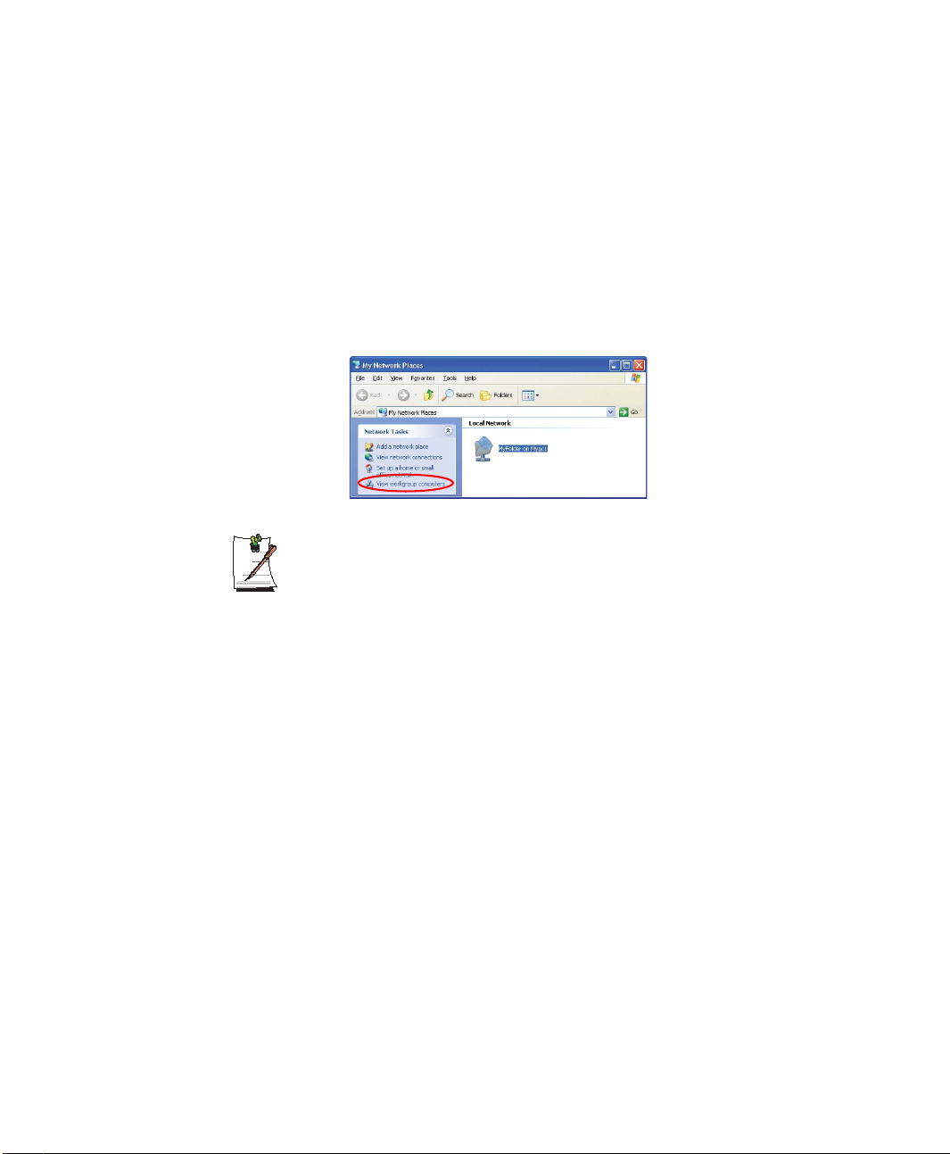
Step 2. Using Shared Files or Folders
This section describes how to access shared files or folders if your computer is a
member of the same workgroup.
1. Click Start > My Computer. Under Other Places, click My Network Places in
your computer.
2. Click 'View workgroup computers', and click the desired computer to access the
shared file.
If your computer is a member of another workgroup:
1. Click Other Places > Microsoft Windows Network.
2. Click the desired workgroup.
3. Click the desired computer to display the shared files or folders.
Sharing Printers
This section describes how to share a printer between computers connected to a
network.
To share a printer, complete the following procedures:
• Step 1. Configure printer sharing in the computer connected to the printer.
• Step 2. Add and use the shared printer in other computers on the network.
Connecting to the Internet 37
Page 53
Step 1. Configuring Printer Sharing
1. From the computer connected to the printer, click Start > Printers and Faxes.
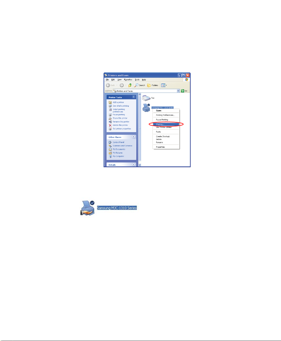
2. Right-click the printer you want to share, and click Sharing.
3. Select 'Share this printer', enter a share name for the shared printer, and click OK.
4. In the Printers and Faxes window, you will find the printer icon has been changed
to another icon on a hand.
Step 2. Adding and Using a Shared Printer.
1. From a different computer that wants to use the shared printer, click Start >
2. Click Add a printer.
3. In the Add Printer Wizard, click Next.
4. Select 'A network printer, or a printer attached to another computer', and click
38 Users Manual
Printers and Faxes.
Next.
Page 54
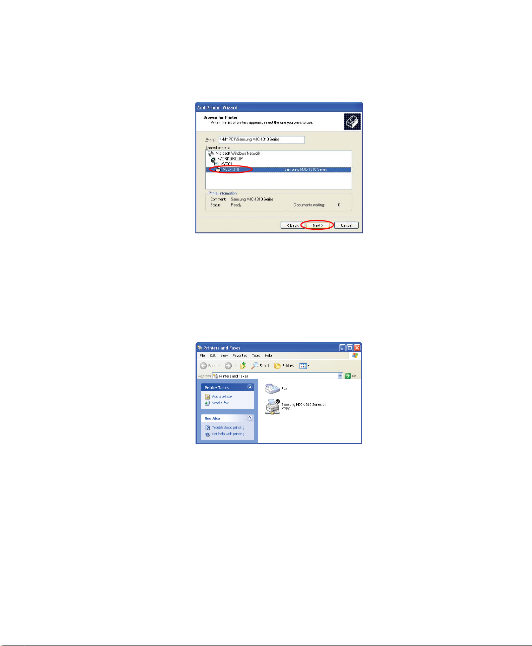
5. Select 'Browse for a printer', and click Next.
6. Select the workgroup or computer, select the desired printer, and click Next.
If you cannot find the desired printer, try again after a while.
7. Read the warning about a shared printer, and click Yes to install the shared printer.
8. Select Yes for 'Do you want to use this printer as a default printer?', and click Next.
9. Click Finish.
10. When the printer sharing configuration has been completed, the shared printer
appears in the Printers and Faxes window.
Now you can print using the shared printer even if your computer is not directly
connected to a printer.
Connecting to the Internet 39
Page 55

Sharing an Internet Connection
Using computer-to-computer (peer-to-peer) network connections, you can access the
Internet through a computer connected to the Internet even if your computer is not
directly connected to the Internet.
To share an Internet connection, the computers should be connected to a
computer-to-computer (peer-to-peer) wireless network. For details, see
“Connecting to computer-to-computer networks (peer-to-peer or ad hoc)” on
page 28.
Also, one of the computers has to be connected to the Internet (external
network).
The configuration procedure to share an Internet connection are described for
Windows XP installed computers.
To share an Internet connection, complete the following procedures:
• Step 1. Configuring a Internet connection sharing from the computer connected
to the Internet.
• Step 2. After completing the shared Internet connection configuration, check
that the other computers can access the Internet through the shared Internet
connection.
Step 1. Configuring Internet Sharing.
Configuring a shared Internet connection on the computer connected to the Internet.
1. Click Start > Control Panel > Network and Internet Connections > Network
2. Right-click on the device connected to the Internet, the external network, and
40 Users Manual
Connections.
select Properties.
Page 56
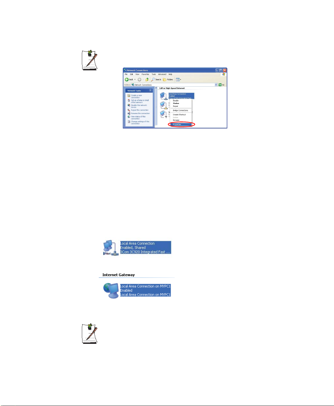
If the computer is connected to the Internet through a wired LAN, select 'Local
Area Connection'.
3. On the Advanced tab, select 'Allow other network users to connect through this
computer's Internet connection', and click OK.
Step 2. Checking the Shared Internet Connection.
When the Internet connection sharing configuration has been completed, the network
icon in the Network Connections window is displayed as follows:
Click Start > Control Panel > Network and Internet Connections > Network
Connections.
– A computer connected to the Internet.
– A computer sharing the remote Internet connection (other computer).
If the icon does not appear after a long time, restart the computer.
Computers on the network can access the Internet through the shared Internet
connection only when the computer connected to the Internet is turned on.
Connecting to the Internet 41
Page 57
Using the Flex-Bay
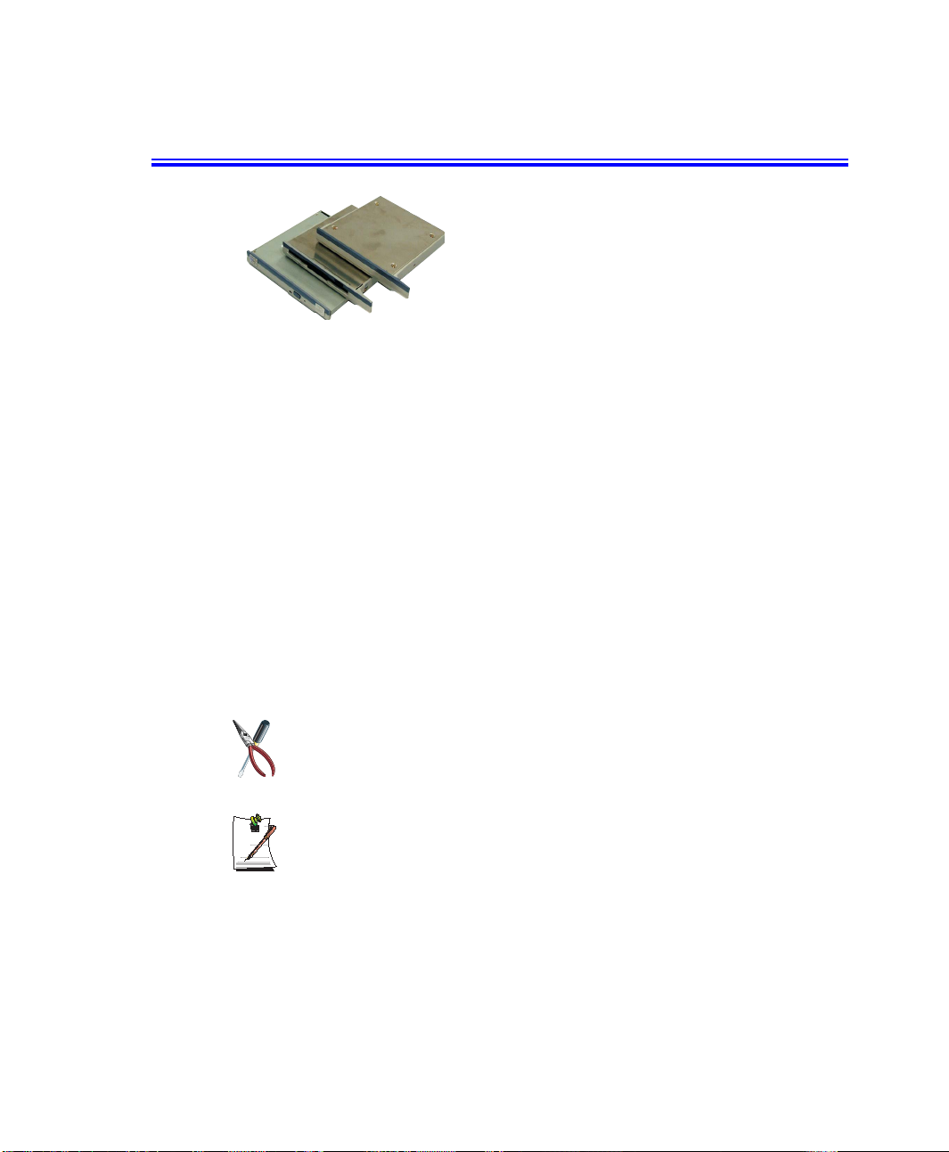
The flex-bay provides an impressive array of secondary storage devices listed below.
These are available as an option for your computer.
• CD-ROM drive
• CD-RW drive
• DVD-ROM drive
• CD-RW/DVD-ROM combo drive
• DVD multi drive
• FDD drive
• 2nd HDD drive
• Weight Saver
42 Users Manual
If your operating system is Windows, you must install the Softex Bay Manager
software on the software CD in order to use the Bay Manager Utility to swap
the devices while the power is on.
If you do not use Windows, make sure that the computer’s power is off before
you remove or install any devices.
Page 58

Swapping a Flex-Bay Device - Power Off
To remove a device with the power off proceed as follows:
1. Turn the computer’s power off.
2. Tilt the computer up and locate the flex-bay latch.
3. Slide and hold the latch toward the rear of the computer.
4. Slide the device out.
5. Carefully slide the new device into the bay.
6. Push the device in until it is flush with the chassis and the flex-bay latch snaps into
place. Your computer’s operating system automatically recognizes the device in
the flex-bay and configures your computer accordingly when power is restored.
Swapping a Flex-Bay Device - Power On
You are recommended to turn the system off before swapping devices, but you can use
the Softex Bay Manager utility to swap devices in the flex-bay while the power is on.
To start the Softex Bay Manager utility:
1. Click Start > Control Panel > Other Control Panel Options > Softex Bay
Manager.
- or -
2. Double-click the SwapBay icon in the Windows taskbar.
Using the Flex-Bay 43
Page 59
To swap a device with the power on proceed as follows:
1. Start the Softex Bay Manager Utility.
You do not have to turn the computer over or tip it on its side to change
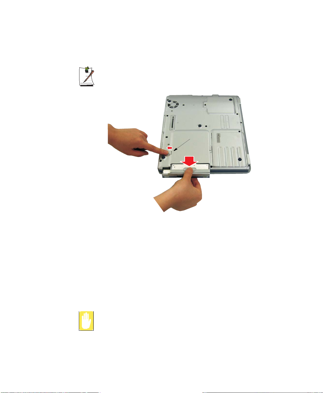
devices. Simply tilt the computer up about 10 cm at the back and locate the
Flex-Bay latch. See Figure below for the location of the Flex-Bay latch. The
computer in the figure is turned over for clarity.
Flex-Bay Latch
2. Click Remove / Swap. A Device Change popup window stating, “Please wait until
3. Tilt the computer up and locate the flex-bay latch.
4. Slide and hold the latch toward the rear of the computer.
5. Slide the device out.
6. Slide the new device in
7. Click OK. The message “Please wait until the system processes the device
8. Click OK to close the Softex Bay Manager Utility.
44 Users Manual
the system processes the device change” appears then another popup window
appears and says, “Please remove or swap your bay device(s) now and press OK.”
change” appears again.
If you swap devices while the power is on without using the Softex Bay
Manager Utility, the device and the system may be damaged.
Page 60
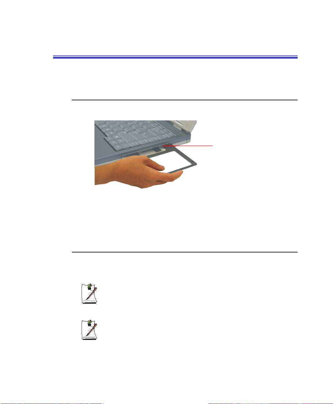
Using the Disk Drives
To use the Floppy drive or the CD-ROM drive you must verify it is installed in the flexbay slot. To swap devices see “Using the Flex-Bay” on page 42.
Using the Floppy Disk Drive (Option)
To use a floppy disk in your computer, insert it into the floppy drive.
To remove a floppy disk, press the floppy disk eject button on the front of the floppy
drive.
To protect the data on your floppy disks, follow the manufacturers guidelines.
Floppy Disk Eject Button
Using the CD-ROM Drive (Option)
Compact discs are designed so that you can easily insert one into the computer when
you need it, and then remove it.
You have to install the CD Writer software provided on a separate CD to write
a CD. For more information, read the manual included in the CD.
You have to install the DVD software provided on a separate CD to view a
DVD title.
Using the Disk Drives 45
Page 61
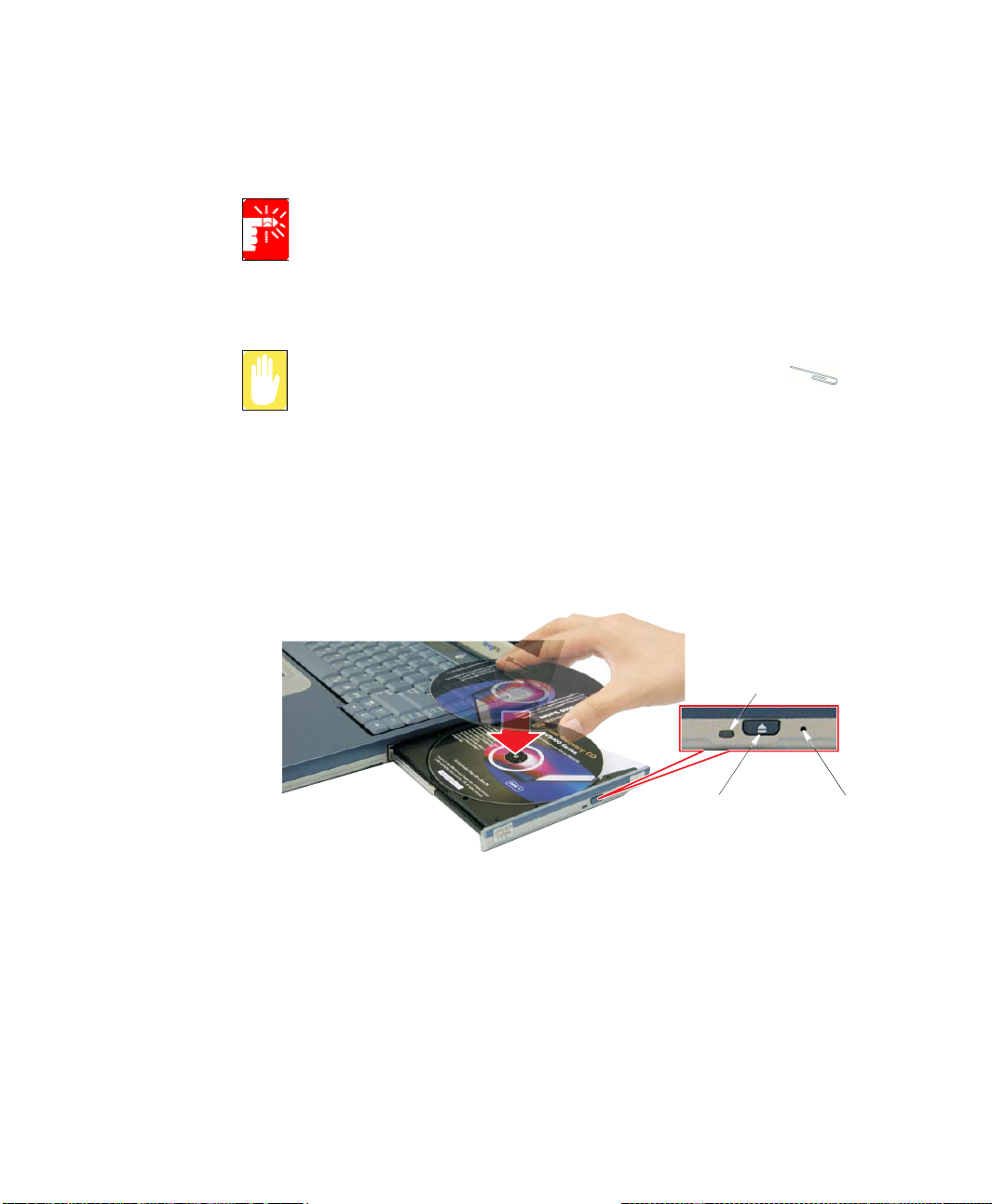
1. Press the button on the CD-ROM drive, and the tray slides out.
(Do not lean on the tray; because it will not support much weight.)
CD-ROM Drive Warnings:
Do not place reflective objects other than the CDs in the disk slot because of
possible hazardous laser emissions. The laser beam used in this CD-ROM
drive is harmful to the eyes. Do not attempt to disassemble the CD-ROM drive.
Refer servicing to your authorized service center.
Do not touch the CD lens, doing so may damage the device.
CD Precautions:
The tray may be stuck, in which case straighten out a paper clip, insert
it into the Emergency Eject hole in the front of the CD-ROM drive and push it
until the tray ejects.
A LED on the drive tray is on when the computer is reading from a CD. Do not
remove a disc when this LED is on.
To clean a CD, wipe from the center outwards with clean and dry cloth.
Remove the CD when the drive activity LED is off.
2. Insert a CD, label side up (or remove a disc, if you have finished using it).
3. Push the tray in gently to close the drive tray.
Install and/or start a CD-based program as you would run a program on a floppy disk.
46 Users Manual
CD-ROM LED
Eject Button
Emergency
Eject Button
Page 62
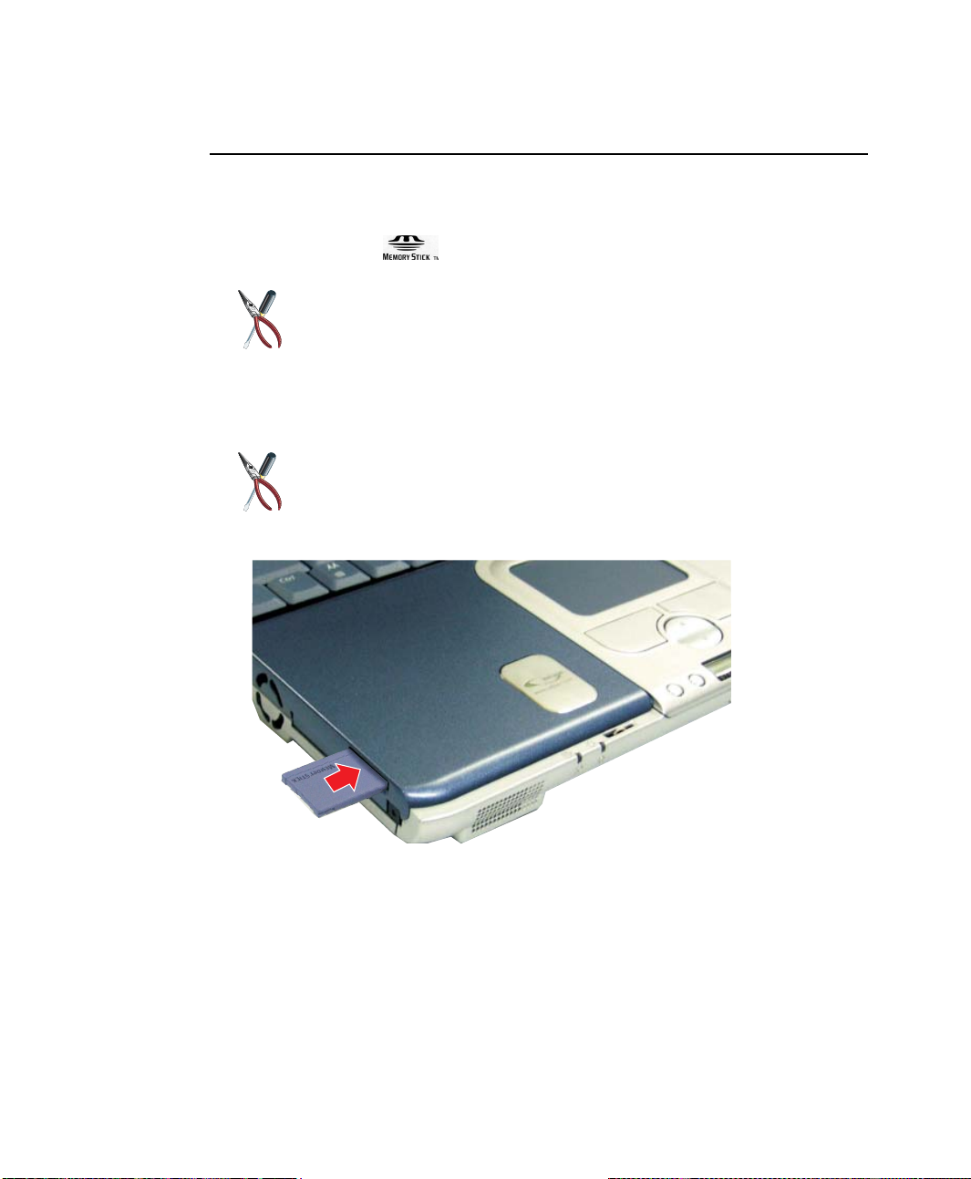
Using the Memory Stick (Factory Option)
The memory stick is a factory option that will increase your computer storage capacity as well
as increase data portability. The memory stick may used in many types of equipment such as
digital cameras and PDAs for example.
Memory Stick and are a trademarks of the Sony Corporation.
Memory Stick Support
The Magic Gate model is not currently supported.
Inserting the Memory Stick
To insert the memory stick proceed as follows:
Ensure you Insert the memory stick into the slot with the correct orientation
(Name Up) so that the Memory Stick will operate properly and be recognized
by the computer.
1. Slide the memory stick into the slot until you feel the first latch catch.
2. Then push the memory stick in until it clicks into place.
Using the Disk Drives 47
Page 63
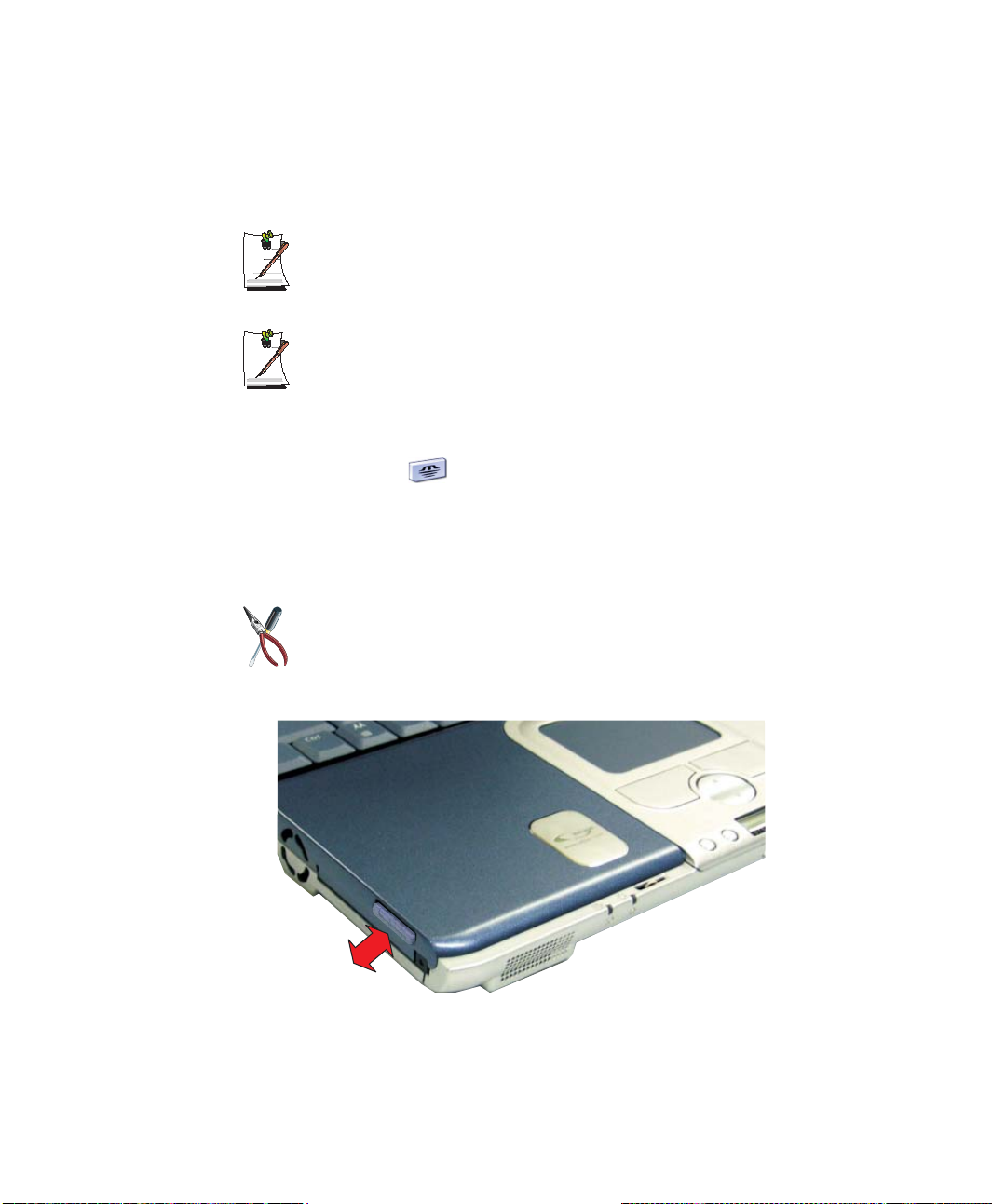
Using the Memory Stick
The memory stick is used the same as the FDD drive on your computer but with much
larger capacity, currently up to 128MB.
Formatting the memory stick
The memory stick may need to be formatted before use, if so insert it into the
slot and format it the same as the FDD Drive.
Protecting Data on the memory stick
To prevent overwriting/deleting your data in the memory stick, move the slide
lock to the “Lock” position.
to see the contents of the memory stick:
1. Double-click “My Computer” on the desktop, the My Computer window opens.
2. Double-click the icon in the Devices with Removable Storage section of the
window.
Removing the Memory Stick
To use the Memory Stick proceed as follows:
Ensure any operations using the Memory stick have completed before you
remove it. Otherwise you will corrupt your data.
1. Push the memory stick in until it clicks and release.
2. The memory stick will pop out about 1 cm and then you can slide it out.
48 Users Manual
Page 64

Working with PC Cards
By installing PC cards, you can add functions to your notebook computer similar to
those found on add-in boards for desktop computers. Available PC cards include:
• Input/output, such as modem, network, video capture, and SCSI cards.
• Storage, such as hard drive and flash memory cards.
Your computer includes the following PC card support:
• One PC-card slot: You can install PCMCIA type I or II cards in the slot.
• CardBus hardware and software: CardBus enables the computer to use 32-bit
PCMCIA cards. Windows supports 32-bit and 16-bit PC cards.
The PC card slot does not support PCMCIA type III card or ZV card.
Maintaining PC Cards
To maintain your PC Cards, follow these guidelines:
• Keep cards away from excessive heat, direct sunlight, and liquids.
• Do not drop, bend, flex, or crush cards when handling.
• Keep dust, magnets, and static electricity away from PC Cards.
• When a card is not in use, carry it in its protective carrying case.
• Some PC cards include cables that extend from the back of the cards. Be careful
not to bend or put excessive strain on these cables.
Working with PC Cards 49
Page 65
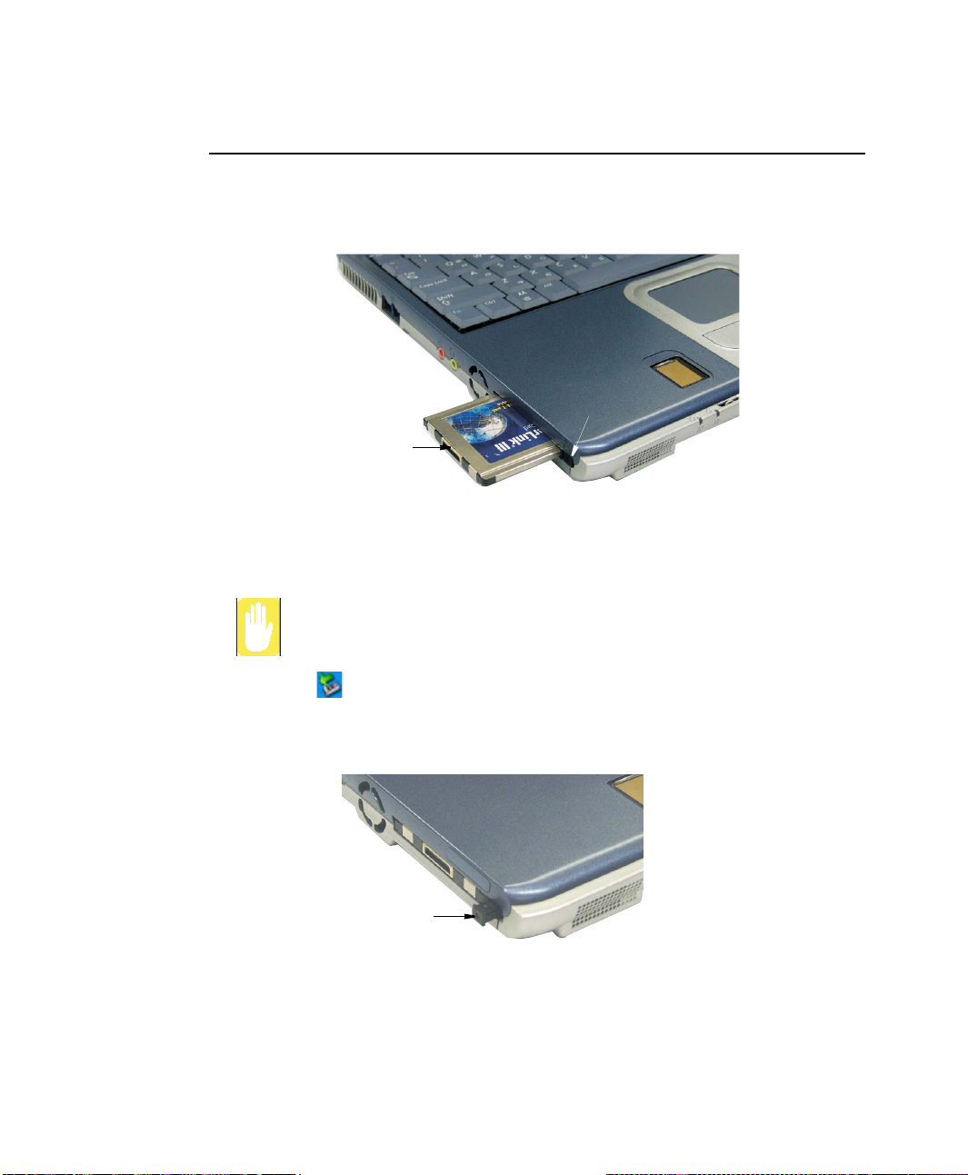
Using PC Cards
To insert a PC card into a slot:
1. Push the slot door in with the PC card.
2. Align the card with a slot and insert the card into the slot until it locks in place.
PCMCIA Card
Eject button
PC Card :
Insert PC card with product
information facing up
Windows automatically assigns computer resources (such as communication ports and
memory addresses) to a PC card installed in your computer.
To remove a PC card from your computer:
Use the following procedures to remove PC cards, or you may lose data that
is being stored to a card.
1. Click icon on the taskbar.
2. Select the card currently in use, and click the Stop button.
The eject button for the card slot operates in two steps, therefore to remove a PC
card:
3. Push the eject button once to pop it outward then push the eject button again to
4. Pull the card out of the PC card slot.
50 Users Manual
PCMCIA Card
Eject button
eject the card.
Page 66

Multi Media Functions/Equipment
Media Player
The Windows Media player is used to play audio files while the computer is on. You
can play audio/video CD files using the Windows Media Player, as well as watching
TV, video and listening to the radio through internet. The instructions to play a video
CD-ROM are the same as the instructions for the audio CD below.
Playing a Audio/Multimedia CD
To play an CD follow the instructions below:
1. Insert a compact disc into your CD-ROM drive.
2. Press the eject button on the CD-ROM drive to open the CD-ROM device.
3. Insert a CD, label side up.
4. Carefully push the tray in to close the drive tray. The Windows Media Player
button appears on the taskbar if not already there, and the music begins to play. If
the disk does not play, click Start > All Programs > Accessories >
Entertainment > Windows Media Player.
CD-ROM LED On:
A LED on the drive tray is on when the computer is reading from a CD. Do not
remove a disc when this LED is on.
Removing the Audio/Multimedia CD
To remove the CD follow the instructions below:
1. Click Start > All Programs > Accessories > Entertainment > Windows Media
Player to open the Windows Media Player window, if not already open.
2. Click Stop in the Windows Media Player window or simply close the Windows
media player.
3. Press the button on your CD-ROM drive. The drive tray opens and you can remove
the CD from the CD-ROM drive.
4. For more information on playing compact discs, see the Help menu in the
Windows Media Player window.
Multi Media Functions/Equipment 51
Page 67
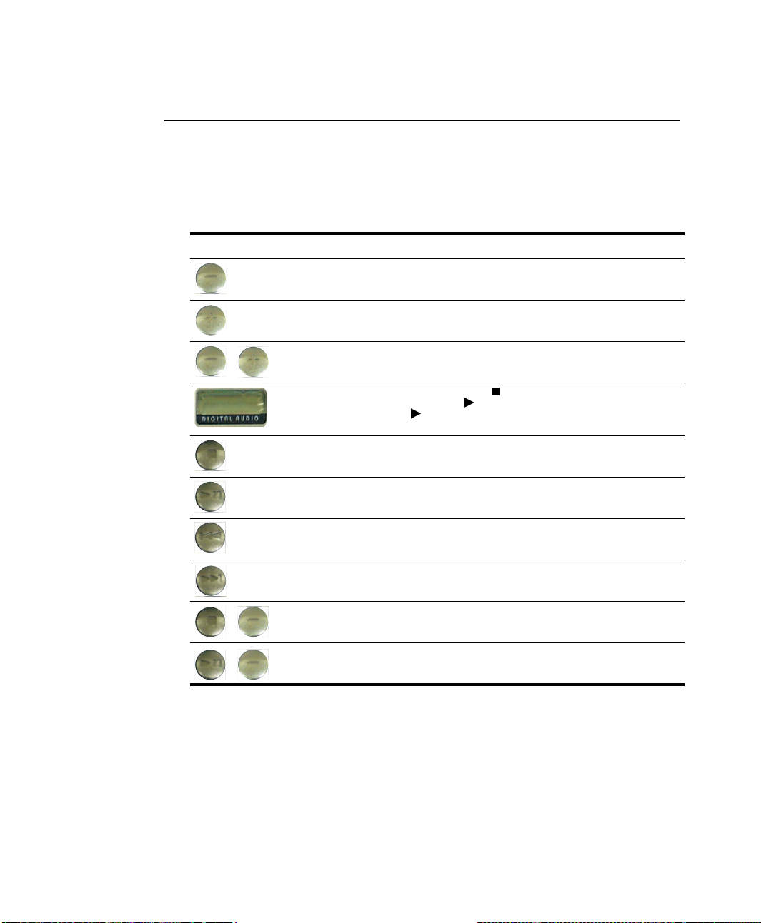
MP3/CD Player (Factory Option)
The MP3/CD Player can play music CDs and MP3 files while the computer is off. It
will not, however play video CDs.
Button Operation
The buttons and display for the MP3/CD Player operate as follows:
Button Name Function
Volume Down Decreases speaker volume when MP3/CD Player is on.
Volume Up Increases speaker volume when MP3/CD Player is on.
+
Mute Press the <Volume Down+Volume Up> buttons simultaneously
Track Display Indicates power on => and total tracks available on CD and
Player Off/
Stop/Eject
Player On/
Play/Pause
Previous Track/Song
Fast Search Reverse
Next Track/Song
Fast Search Forward
Lock Press the <Player Off/Stop/Eject+Volume Down> buttons
+
Unlock Press the <Player On/Play/Pause+Volume Down> buttons
+
for 1 sec. to mute the sound.
track playing => .
The blinks when the music file is paused.
Stops and Ejects the Audio CD.
Press the button for 3 seconds to turn off the MP3/CD Player.
Starts/Pauses the Audio CD and MP3 Files.
Turns on the MP3/CD Player.
Changes the Audio CD to the previous track/song.
Changes the Audio CD to the next track/song.
simultaneously for 3 sec. to lock the MP3/CD Player buttons.
simultaneously for ~ 3 sec. to unlock the MP3/CD Player buttons
and energize the MP3/CD Player.
52 Users Manual
Page 68

Using the MP3/CD Player
Play an Audio CD
1. Verify the computer is off and that a CD-ROM device is in the flex-bay.
Player On/Play/Pause Button:
If a CD-ROM device is not in the flex-bay, the Player On/Play/Pause button
button will not turn on the MP3/CD Player.
Computer Button Operation:
MP3/CD Player buttons are not functional when the system is turned on. To
use the MP3/CD Player buttons while the system is on, you must start the
Windows media player.
2. Press the Player On/Play/Pause button until the track display window
[Labeled: DIGITAL AUDIO] is turned on.
3. Press the eject button on the CD-ROM drive or the Player Off/Stop/Eject button
on the MP3/CD Player.
4. Insert a Audio CD into your CD-ROM drive label side up.
5. Press the Player On/Play/Pause button on the MP3/CD Player.
Pause/Resume an Audio CD
1. Press the Player On/Play/Pause button to pause the CD.
2. Press the Player On/Play/Pause button again to restart the CD.
Stop an Audio CD
1. Press the Player Off/Stop/Eject button to stop and eject the CD.
2. Remove the Audio CD, then close the tray.
3. Press the Player Off/Stop/Eject button for 3 seconds to turn off the MP3/CD
Player.
Fast Search an Audio CD
1. Press the Next or Previous buttons for 1 second while the music is playing
to start Fast Search.
2. Press the Player On/Play/Pause
to stop the Fast Search.
button and Next or Previous buttons
Multi Media Functions/Equipment 53
Page 69

Dolby Digital & Home Theater System (S/PDIF Port)
This product supports 5.1 channel output, which is a basic function for home theater
systems and DVD drives. It provides 3D surround sound and a vivid screen.
Home theater system usually consists of a TV, DVD, 5.1 channel speakers,
and a digital amplifier to provide a high-resolution vivid (MPEG2) picture and
3D surround sound (Dolby 5.1 or DTS). With a home theater system, you can
enjoy the same vivid picture and sound in your home that you would in a movie
theater.
You will need the following to enjoy a home theater system:
• 5.1 channel speaker system / Digital amplifier (Purchased separately)
• DVD drive and DVD Program (Option)
• S/PDIF cable (Purchased separately)
• When purchasing a 5.1 channel speaker system, make sure it supports a S/
PDIF (coaxial) port.
Setting Up Your Home Theater
1. Connect the digital amplifier to the S/PDIF port of your computer.
To Digital Amplifier
54 Users Manual
S/PDIF Port
Page 70
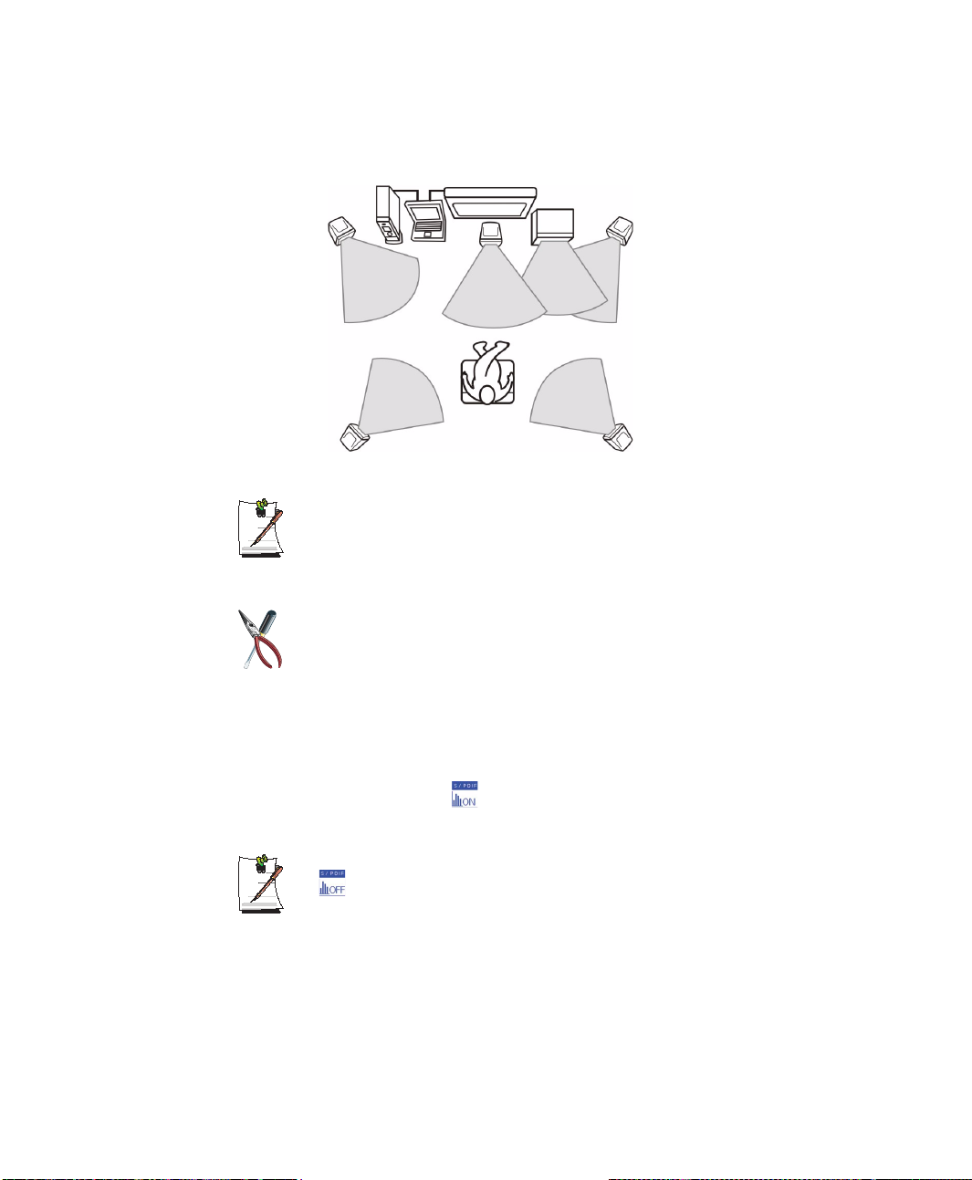
2. Connect the speakers to the digital amplifier.
Digital Amplifier
Front Left Speaker
Surround Left Speaker Surround Right Speaker
Computer
TV
Center
Speaker
Sub
Woofer
Front Right Speaker
If your computer supports a TV-Out port, you can connect and enjoy a large
screen.
After connecting the TV, you will need to select the TV as the display device
using the Windows Display Properties window.
After making all connections, ensure you enable S/PDIF:
1. Enable S/PDIF in Windows.
2. Enable S/PDIF in the DVD program.
Using the S/PDIF Connection
1. Use <Fn+F8> keys to set the S/PDIF port to digital.
2. If it is setup correctly, [
keys.
To use the headphones, press <Fn+F2/Gauge> keys to change the setting to
[ S/PDIF Off].
S/PDIF On] appears when you press <Fn+F2/Gauge>
Multi Media Functions/Equipment 55
Page 71
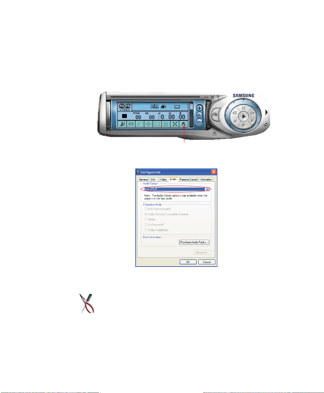
Enabling S/PDIF on the DVD Program
When using 5.1 channel speakers, you will need to install the “Power DVD” program
on the DVD Installation CD (supplied separately) and then set it up as described below:
1. Run the “Power DVD” program and click the settings button, the configurations
window pops up.
Settings Button
2. On the Audio tab, change the Audio Output setting to “Use SPDIF” and click OK.
3. You are ready to enjoy your home theater system with your own DVD’s.
56 Users Manual
• If you have enabled S/PDIF in the DVD program, the computer speakers
and headphone are not functional.
• To control the sound volume on your 5.1 channel speaker system, use the
control on the digital amplifier. (Please refer to the speaker manual.)
Page 72

Volume Control
The instructions below are for controlling speaker volume when the computer is on. To
control speaker volume when the MP3/CD Player only is on, see “MP3/CD Player
(Factory Option)” on page 52.
Using the Keyboard
Changing the volume with your keyboard.
Use <Fn+PgDn> to decrease the volume or <Fn+PgUp> to increase the volume.
Using the Volume Control Icon
Double-click icon on the taskbar. The Volume Control window pops up. Use this
window to adjust the volume. You can pop up a simple volume slider by a single click
icon.
Movie Maker
You can edit audio and video data using this Movie Maker included with Windows XP.
It is also possible to make a slide show with each frame or picture.
To start the program:
Click Start > All Programs > Accessories > Windows Movie Maker.
Please refer to the on-line help manual to operate the Windows Movie Maker.
Multi Media Functions/Equipment 57
Page 73

Using the Battery
Your computer uses a smart rechargeable Lithium-ion (Li-ion) battery pack for power
when the AC adapter is not attached to an electrical outlet. The smart battery gives an
accurate measurement of the current battery capacity which helps extend operating
time by enabling effective power management in operating systems that take
advantage of the accurate information supplied by the battery.
Charging the Battery
Your computer’s battery starts charging automatically when you connect the power to
the computer and to an electrical outlet. If the computer is off, the battery charges faster
than if the computer’s power is on.
Approximate charging times for the Li-Ion battery are
• 3 hours with the computer off.
• 6 hours with the computer on.
While the battery is charging normally, the battery status LED on the computer is
amber. When the battery is fully charged, the LED changes to green.
When you use a new battery pack for the first time or use a battery after a long period
of storage, the initial battery life is shorter than normal. Normal battery life resumes
after a few discharge-recharge cycles.
Follow these rules for charging your battery:
58 Users Manual
• A battery normally discharges power when not used for long periods of time.
Be sure to recharge the battery every two months when it is not in use.
• Make it a practice to discharge your battery fully before recharging the battery.
This can help extend the life of the battery.
• Do not attempt to charge the battery in temperatures of under 5
All batteries eventually wear out and lose the ability to hold a charge. You may
need to replace your battery pack after a year of average usage.
o
C or over 45oC
Page 74

Safely Using the Battery
Follow these guidelines to safely use the battery:
• Turn off your computer and unplug it if you accidentally:
– Expose the equipment to liquid.
– Drop, jar, or damage the computer.
• Use only approved battery chargers.
• Do not disassemble the battery, heat it above 100°C, or burn it. The battery
used in this computer may cause a fire or chemical burn if mistreated.
• Your computer's rechargeable battery may be considered hazardous waste. If
you replace your battery with a new one:
– Keep the old battery out of the reach of children.
– Dispose of the old battery promptly.
– Make sure that you follow all local requirements when you dispose of the
old battery.
Removing the Battery
Your computer comes with the battery pack inserted in the computer.
To remove the battery from the computer:
1. Turn the computer’s power off.
2. Close the LCD panel, and turn the computer over so that the bottom of the unit
faces up.
3. Slide the battery compartment latch toward the left side of the computer and hold,
this raises the battery slightly.
4. Slip your fingernail under the edge of the battery and pull it up and then grab the
battery and remove it from the compartment.
Using the Battery 59
Page 75
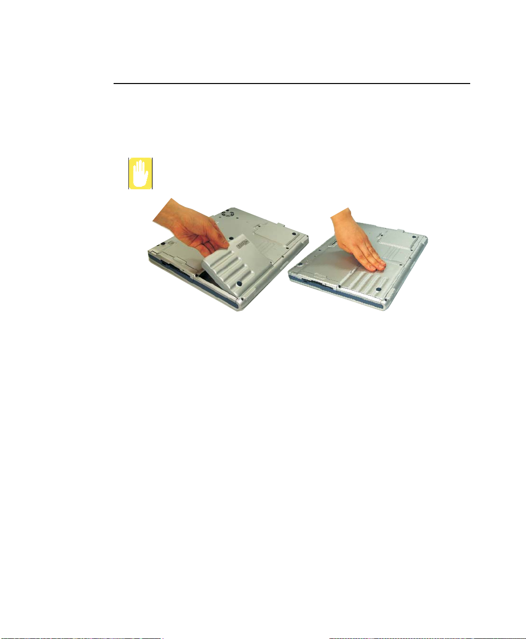
Installing the Battery
To install the battery pack:
1. With the computer’s power off, close the LCD panel and turn the computer over
so the bottom of the unit faces up.
Insert the battery into the battery compartment, ensuring the correct
orientation so that the battery fits in its slot properly.
2. Place the battery inside and against right side of the computer battery compartment
at an angle of approximately 30 degrees.
3. Push the battery down until the latch snaps into place, securing the battery.
60 Users Manual
Page 76
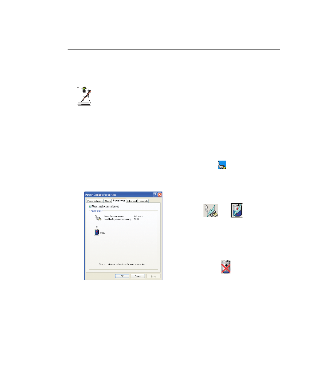
Monitoring the Battery Charge
Battery life is affected by factors such as the power-management settings in System
Setup, the applications you use, and the brightness settings of the LCD. Under normal
usage, the battery charge lasts approximately 2.5 hours.
Battery life estimates are subject to variation. The actual life of your battery
may be less than the estimates given in the manual.
You can monitor the charge of the battery pack installed in your computer by using the
Power Meter or Battery Gauge.
Power Meter
The Power Meter displays the charge of the batteries and the current source of
computer power, AC or batteries. You may monitor the battery charge or usage by
using the “Power Meter”. To access the power meter, click icon on the taskbar or
click Start > Control Panel > Performance and Maintenance > Power Options >
Power Meter tab.
The Power Status icons shown below are displayed
during Battery Charging Operations.
At ~15% and 10% remaining battery power the
current power source and the battery Icons
respectively change to the icon shown below and
you should follow the instructions in “Battery
Warnings” section below.
Using the Battery 61
Page 77
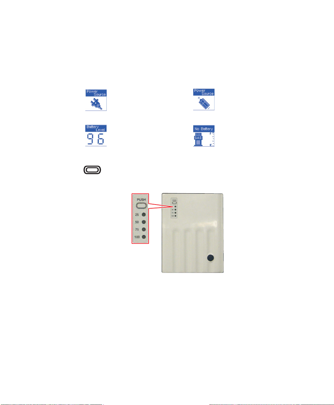
Battery Gauge
You may display the battery gauge while you are in any program by pressing
<Fn+F2>. While the battery gauge is being displayed, all keys except <Esc> are
disabled. The battery gauge is only displayed for a few seconds.
Power Source:
Indicates that the computer is powered
by the AC adapter.
Battery Level:
Indicates the approximate amount of the
primary battery charge remaining.
You may also determine the charge of your battery by simply pushing the symbol
below the word PUSH located on the bottom of the battery. The green LEDs
will illuminate to show you the percentage of charge remaining in the battery.
Indicates that the computer is powered
by the battery.
Indicates the computer is on AC power
only.
(No Battery Present).
62 Users Manual
Page 78

Battery Warnings
If the battery charge is low (about 10%) you have 5–10 minutes of battery life left.
You should:
• Save your work and,
• Connect the power cord to the computer or turn off the computer and install a
fully charged battery.
You can adjust the battery alarm features by using the operating systems power
management program (Start > Control Panel > Power Options in Windows).
If you cannot run your computer from the battery and the battery will not charge when
you attach the power cord, the problem may be that:
• The battery temperature is below 0°C or over 45°C. If you think the battery
temperature is too hot or too cold, turn off the computer, remove the battery,
and let the battery reach room temperature. Then try charging the battery again.
• The battery is defective. Replace the battery with a new battery.
Battery Calibration
Calibrating your battery once a month is one of the recommended methods of
increasing your computer’s battery life. To calibrate the battery, complete the
following steps:
Calibration Notes:
You should start the battery calibration process with a fully charged battery,
battery status LED is green. The power meter may not show 100%.
Before you commence the battery calibration process, you should fully charge,
then fully discharge and finally fully recharge the battery again.
1. Disconnect the AC adapter after turning off the system.
2. Restart your computer and press <F2> to enter system setup.
3. Using the arrow keys, highlight Smart Battery Calibration in the Boot menu.
4. Press <Enter> to start calibration process. The calibration usually takes 3 to 4
hours depending on the current battery charge.
5. When the calibration process is complete, recharge the battery fully.
Using the Battery 63
Page 79
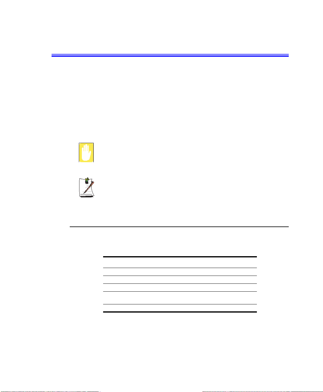
Using System Setup
The System Setup (BIOS) program enables you to configure your computer hardware
and set security and power-savings options. The settings you choose are stored in
battery-maintained CMOS memory that saves the information even when the
computer’s power is turned off. When your computer is turned back on, it is configured
with the values found in this memory.
Run System Setup if you get a message prompting you to run the program. You may
also want to run System Setup, particularly the first time you use your computer, to set
the time and date, use security or power-management features, or alter the settings of
other features.
BIOS Caution:
If you are not familiar with system setup and what the parameters mean, seek
help from a person who is knowledgeable. Incorrect settings may cause your
system to “Crash”.
Your computer’s version of system setup may not include all the fields listed
here or may include additional fields. Field names and order of appearance
can vary according to the version of the BIOS (basic input/output system) on
your computer.
Starting System Setup
To start system setup, turn on your computer and then press <F2> and hold until the
system setup screen appears.
To open the menu you need to use, use the left or right arrow keys to select the menu
name.
64 Users Manual
Table 3. System Setup Menus
Menu Function
Main Changes the basic system.
Advanced Configures advanced features on your computer.
Security Enables security features, including passwords.
Boot Specifies the order of boot devices and configures boot
Exit Specifies how to exit System Setup.
features.
Page 80

Table 4. System Setup Navigation Keys
Navigation Key Function
<F1> Displays the General Help window.
<Esc> Exits the current menu.
<Up Arrow> or
<Down Arrow>
<Left Arrow> or
<Right Arrow>
<F5> Scrolls backwards through the options for the highlighted field.
<F6> Scrolls forward through the options for the highlighted field.
<F9> Sets the parameters for the current menu to their default values.
<F10> Save changes and exit system setup.
<Enter> Executes commands or opens a submenu.
Moves the cursor up and down between fields.
Selects different menus. Pressing the <Esc> key at the Main
menu brings you to the Exit menu.
Using System Setup 65
Page 81

Changing Booting Priority
The Boot menu in system setup enables you to select the booting device and to set
booting options.
Boot Device Priority field enables:
You to select the order in which the computer attempts to boot from different devices.
The field has three options: CD-ROM Drive, Removable Devices, and Hard Drive.
To change the booting device priority, choose the device positions by completing
the following:
1. At startup, press <F2> to open System Setup.
2. Use <Right Arrow> to select Boot menu.
3. Press <Enter> on Boot Options.
4. Highlight the 1
5. Press <F5> or <F6> until the option is moved to the desired position.
6. Press <F10> to exit and save your changes.
7. Press <Enter> again to restart the computer.
st Boot Device option with <Up Arrow> or <Down Arrow> keys.
66 Users Manual
Page 82
Configuring the Password
Setting the Supervisor Password
By configuring a supervisor password, you can restrict system access to authorized
users only.
To use a fingerprint in the fingerprint sensor installed model, refer to the
supplied manual for the fingerprint sensor.
1. Select the Security menu in the System Setup. To enter System Setup, see “Using
System Setup” on page 64.
2. On the Set Supervisor Password item, press <Enter>.
3. Enter a password, press <Enter>, re-enter the password for confirmation, and
press <Enter> again.
4. When a message confirming the password configuration appears in the [Setup
Notice] window, press <Enter>.
Setting the User Password
You can configure user passwords so that other users can use the system.
Before configuring a user password, a supervisor password must have been
configured.
Users can start the system with their user password, but cannot enter into the
System Setup.
Deactivating the supervisor password also deactivates the user password.
On the Set User Password item, press <Enter>, and complete step 3-4 of Configuring
the Supervisor Password.
Configuring the Password 67
Page 83

Activating the Booting Password
Before activating the booting password, the supervisor password must have
been configured.
On the Password on boot item, press <F5> or <F6> to set the option to [Text
Password]. If you have fingerprint sensor installed, you can set the option to [Finger
Print] to boot the computer with your fingerprint.
From now on, system booting will not proceed without the password.
Deactivating the Password
1. On the password to delete, press <Enter>. (e.g. supervisor password)
2. Enter the current configured password, and press <Enter>.
3. Leave the 'New Password' and 'Confirm New Password' field empty, and press
<Enter> to deactivate the password.
68 Users Manual
Page 84
Using Power Management Options
Your computer includes Power Management options that can help the battery charge
last longer and extend the life of the battery. Power management options will slow
down or shut off system components when the components are not being used.
Power management may slow down system performance. Your computer runs fastest
with the power cord attached, when power management is disabled.
In the next sections, basic and advanced methods of power management will be
discussed.
Basic Power Management Schemes
This section discusses the basic schemes of power management when the computer is
operating on battery power or using AC power.
Standby vs. Hibernation
Standby unlike hibernation mode does not store unsaved information on your
hard disk; it's stored only in the computer memory. If there is an interruption in
power, the information is lost. So before putting your computer on standby,
you should save your files.
Changing Devices:
Do not change PC cards while in standby or hibernate modes.
To enter the power management window complete the following:
1. Click Start > Control Panel > Performance and Maintenance.
2. Click icon to display the Power Options Properties window.
Using Power Management Options 69
Page 85
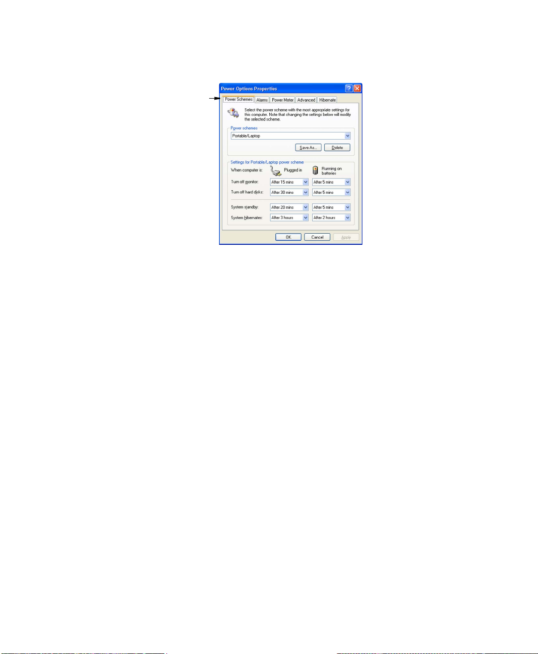
3. Click the Power Schemes tab to display the basic power management options.
Power Schemes Tab
4. Select the time that you wish each of the following actions to occur in Battery and
AC power mode.
• Turn off monitor:
• Turn off hard disks:
• System standby:
• System hibernates:
Turning off the monitor and HDDs will save a substantial battery power, therefore
when in battery only mode, select the shortest time practical.
a Hibernate Mode (Power Management or Manual Method)
70 Users Manual
When hibernation is used, your computer turns off and when you power up again,
everything is restored exactly as you left it—including programs and documents
you may not have saved or closed. Everything in memory gets saved to the HDD,
and the monitor and hard disk get turned off.
Page 86
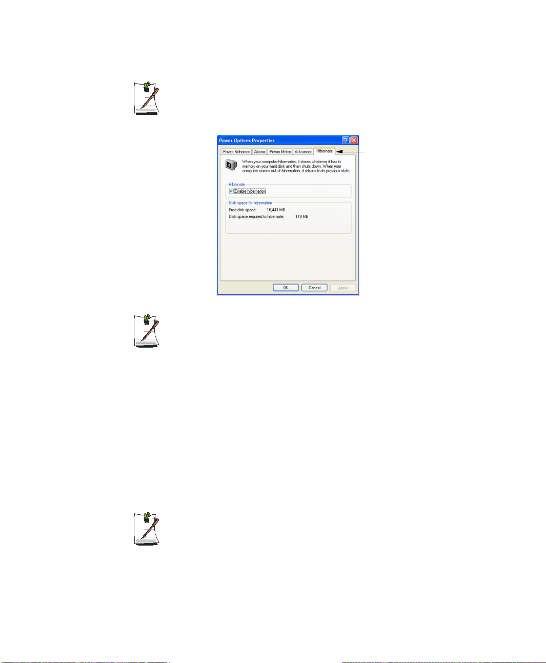
If You Reinstall Windows:
You should re-establish hibernate in power options by opening Power
Options Properties window and click on the Hibernate tab then click
“Enable Hibernation”.
Hibernate Tab
Frequent Interruptions:
If you experience frequent interruptions, you might also consider putting your
computer into automatic hibernation after a specified number of minutes using
the power management options.
a Standby Mode (Power Management or Manual Method)
Standby is used mainly for conserving battery power in your notebook computer. It
also gives you the benefit of getting right back to your work without waiting for the
computer to restart. Standby turns off your monitor and hard disks, placing your entire
system in a low-power state. When you return to your computer, restores your desktop
exactly as you left it. It is recommended that you do not enter standby mode with less
than 20% battery power.
5. Click OK to set your power management options and close the window.
Rest Key:
The manual <Fn+F5> key combination will not activate Standby or Hibernate
modes whilst you are playing a multimedia program or have an active USB
device connected.
Using Power Management Options 71
Page 87
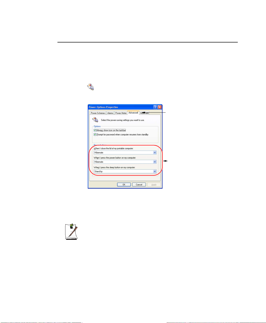
Advanced Power Management Schemes
This section discusses the advanced power management schemes. There are two
buttons that you can use to manually conserve power.
To enter the power management window complete the following:
1. Click Start > Control Panel > Performance and Maintenance.
2. Click icon to display the Power Options Properties window.
3. Click the Advanced tab to display the advanced power management options.
Advanced Tab
Power & Sleep Button
Programming Windows
4. Select the mode (Do nothing/Ask me what to do/Standby/Hibernate/Shut
5. Click OK to set your power management options and close the window.
You can return to normal operation after you have used one of the “Power
Management” buttons by quickly pushing and releasing the Power button.
72 Users Manual
down) assigned to the Power button and/or Rest <F5> key. Also select the action
(Do nothing/Standby/Hibernate) associated with closing the computer lid.
The “Rest” key is assigned to the <Fn+F5> key combination. See ”Basic
Power Management Schemes” on page 69 for a better understanding of
Standby and Hibernate modes.
Page 88

Using the Hard Drive
Your computer includes a removable IDE (integrated drive electronics) hard drive. The
IDE hard drive can store the data and programs your computer uses. The drive plugs
into a connector on the system board.
The hard drive that comes with your computer has already been formatted. Do
not format the hard drive. Doing so destroys all data contained on the drive. If
you need to format a new drive, or want to erase all data on your existing hard
drive, refer to the manual for your operating system.
Installing/Reinstalling a HDD
To install a new HDD you should contact a Service Centre, replacement of the HDD is
not a user task. You should follow the instructions below before the HDD is replaced.
• Back up data files of your old hard drive.
• For system boot with CD-ROM, under the Boot menu in System setup, set
Bootable CD Check to Enabled and set Boot Device Priority is ordered starting
from the [DVD/CD-ROM].
When you are ready to install the new HDD use the Recovery CD-ROM to install the
device driver.
(Re)Installing Windows and Device Drivers
Use System Recovery CD to (re)install OS and System Software CD to (re)install
device drivers. See ”Reinstalling Windows XP” on page 95 and ”Reinstalling
Software” on page 93.
Using the Hard Drive 73
Page 89

Video Features and Configuration
Resolution and Colour Depth
The resolution of the LCD is the sharpness of the image it can display. Resolution is
measured by the number of pixels (individual dots) displayed on the entire screen. In
general, the more pixels the LCD can display, the better the image.
The number of colours the LCD can display is measured by how many bits the LCD
uses to represent each pixel:
• 16-bit colour can support 64 K (65,536) colours.
• 32-bit colour can support 16 M (16.8 million) colours.
All these video modes can be displayed on an external monitor. However, if you
disconnect an external monitor that was attached to your computer and then start the
computer, the LCD may revert to a different resolution than the one you chose for the
external monitor.
Adjusting the LCD Brightness
There are 6 levels of LCD brightness (1: Dimmest ~ 6: Brightest). The default LCD
brightness setting is level 4. Whenever you change the power source, the brightness
level is changed to the following setting:
• When operating on AC power : Level 6 (Brightest)
• When operating on battery power : Level 1 (Dimmest)
Once the LCD brightness has been changed, the changed setting will be maintained
after restarting the computer. When the power source is changed (AC to battery or
battery to AC) while in operation, both the default brightness settings described above
will be restored.
You can adjust the LCD brightness by pressing <Fn+Up Arrow> or <Fn+Down
Arrow> on the keyboard.
74 Users Manual
Page 90
Configuring Display Features
The following sections describe how to configure the display settings on your
computer.
Display Resolution Notes:
When Windows XP is initially installed it will automatically adjust the resolution
to maximum available.
Changing Colour Depth and Resolution
To change the colour depth and resolution of your LCD:
1. Click Start > Control Panel > Appearance and Themes.
2. Click icon. The Display Properties window appears.
3. Click the Settings tab. The Settings screen appears.
4. To change the colour depth, click the arrow next to the Colour quality palette and
select the available colour depth you want.
5. To change the resolution, click and drag the slider under the Screen resolution
until you select the available resolution you want.
6. Click OK.
7. Follow the prompts that appear on the screen.
Using Powerplay
The Powerplay technology supplied with your graphics adapter to extend battery life.
POWERPLAY Use Limitations
Activating POWERPLAY will reduce your graphic card performance.
To activate POWERPLAY proceed as follows:
1. Click Start > Control Panel > Appearance and Themes > Display > Settings
tab > Advanced > POWERPLAY tab.
2. Move the sliders to the left to extend battery life.
Video Features and Configuration 75
Page 91
Using External Display Devices
Using external display devices such as a monitor, projector, TV, etc allows you to view
screen images alternatively or simultaneously on each device. You can also split a
screen into two display devices, or view different images on each display device. Using
external display devices is especially useful when you are giving a presentation or
watching a movie through your TV.
Switching Display Devices Using the Shortcut Key
You can watch the screen through either the LCD or an external display device, or you
can even watch the screen through both the LCD and an external display device
simultaneously.
1. Connect the external display device (e.g. a monitor or a projector) to the
corresponding port of the system.To connect a TV, connect the TV to the TV
output port of the system.
2. Press the <Fn+F4 / LCD/CRT> key. Provided that an external display device is
connected, the display option changes in LCD > CRT > LCD+CRT order
whenever the <Fn+F4/LCD/CRT> key is pressed.
76 Users Manual
Provided that multiple external display devices are connected, the display
order would be LCD > CRT > LCD+CRT > TV whenever the <Fn+F4 / LCD/
CRT> key is pressed. You cannot view the screen via the LCD, CRT, and TV
simultaneously.
You can also use Display Properties to change output display device. Click
Start > Control Panel > Appearance and Themes > Display > Settings tab
> Advanced > Displays tab. Select the desired item, and click OK.
Page 92
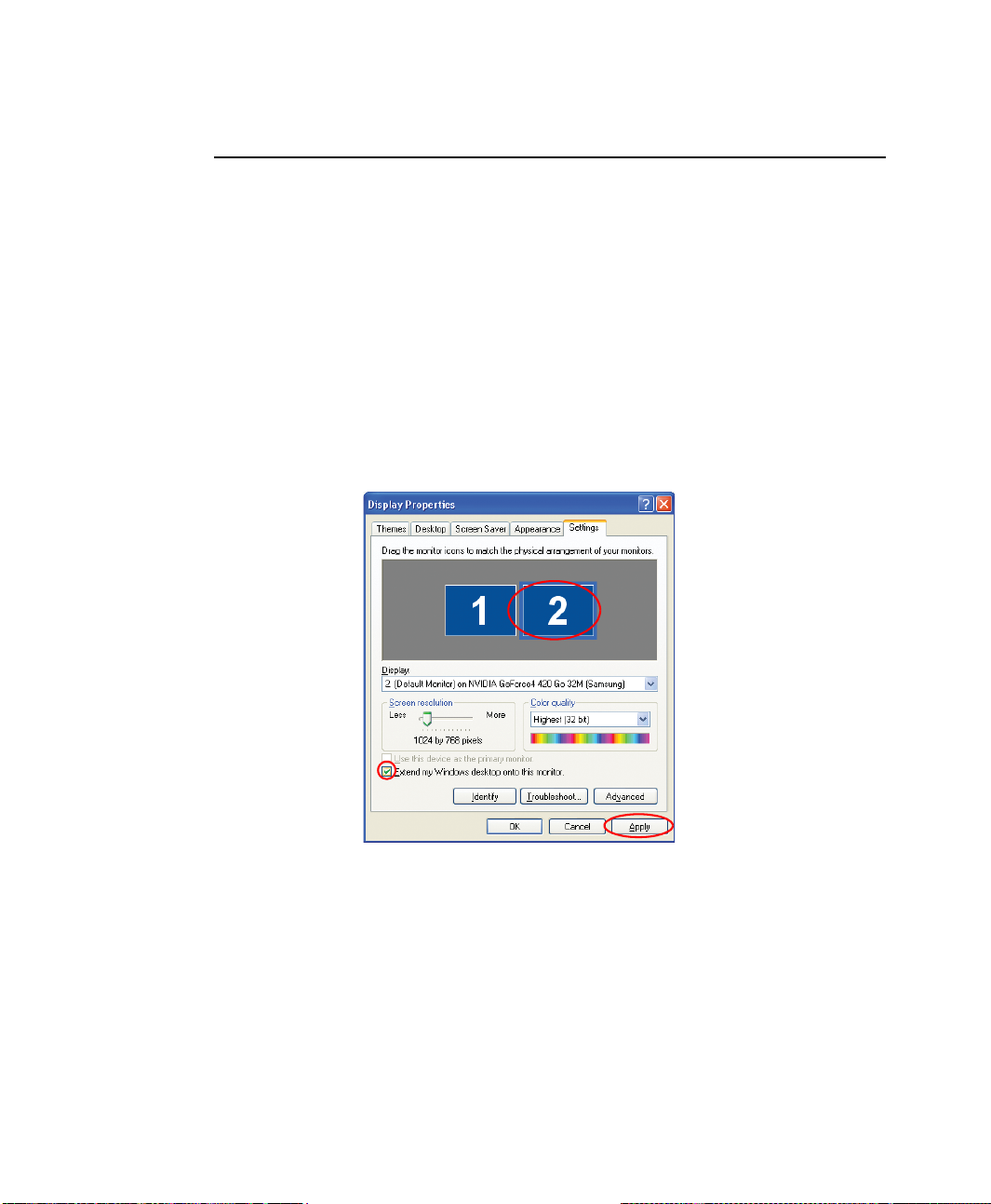
Using Dual View to View Extended Screen
You can expand the screen into two display devices and work conveniently in separate
workspaces.
In Dual View mode, you can select the screen resolution and color quality for each
display device, as if there were two separate graphics cards.
1. Connect the external display device (e.g. a monitor or a projector) to the
corresponding port of the system. To connect a TV, connect the TV to the TV
output port of the system.
2. Click Start > Control Panel > Appearance and Themes > Change the screen
resolution.
3. Click the monitor '2' icon, select the 'Extend my Windows desktop onto this
monitor' check box, and then click Apply.
Using External Display Devices 77
Page 93
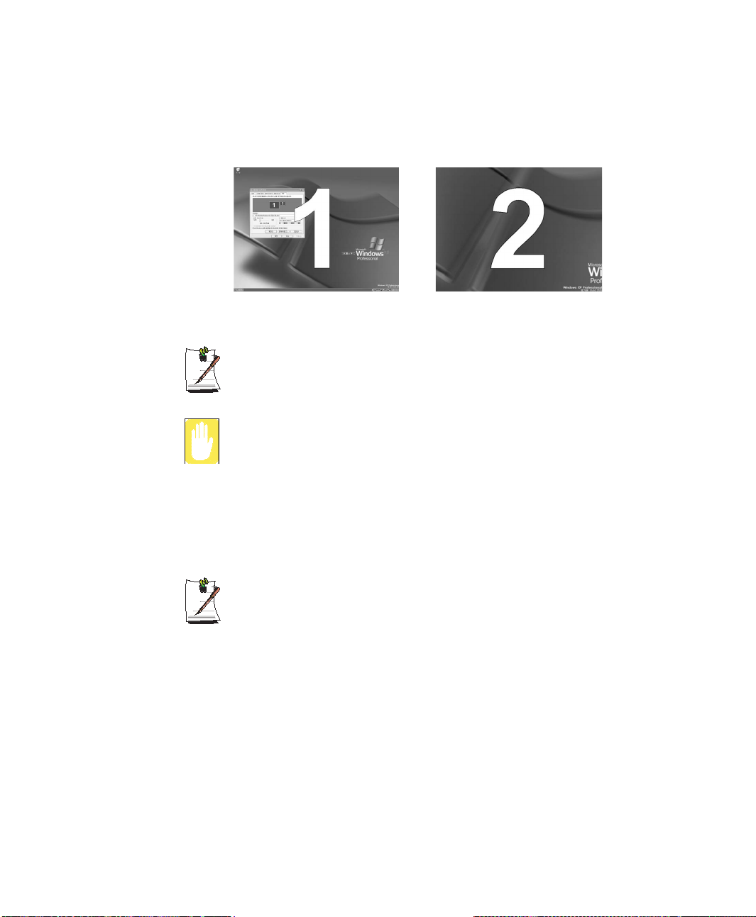
4. Click OK. The primary display device(the LCD) is indicated as '1', and the
secondary display device is indicated as '2'. Now you can use each of the two
display devices as independent display devices.
2 : Secondary1 : Primary
When using Dual View, it is recommended that LCD is kept as '1', the primary
display device.
If the screen of the secondary display device is displayed at 640x480 pixels,
with 256 colors, change the settings to the desired screen resolution and color
quality in the [Display Properties] window.
Deactivating Dual View Mode
Click the monitor '2' icon, clear the 'Extend my Windows desktop onto this monitor'
check box, and then click Apply.
78 Users Manual
To move a window between display devices in Dual View mode
Click the title bar of the window in the primary display device(1, the LCD), and
drag it to the secondary display device (2). The window is move to the
secondary display device.
Page 94

Using Options
You can select these options at purchase:
• Wireless communication module
(802.11b, bluetooth)
• Fingerprinter recognition system / scroll wheel
• Memory stick slot
• Flex-bay
(CD-ROM drive, CD-RW drive, DVD-ROM drive, CD-RW/DVD-ROM
combo drive, DVD multi drive, FDD drive, 2nd HDD drive, Weight Saver)
• FIR (Fast Infrared) Connection
• MP3/CD Player
You can purchse these options separately:
• Extra AC adapter
• Car adapter
• 128, 256 and 512 MB DDR SDRAM memory modules
• Port replicator
• Flex-bay
(CD-ROM drive, CD-RW drive, DVD-ROM drive, CD-RW/DVD-ROM
combo drive, DVD multi drive, FDD drive, 2nd HDD drive, Weight Saver)
The options that are available may change periodically. Contact your reseller for
updated information on current and new options.
Using Options 79
Page 95
Memory Modules
You can increase system memory by installing optional memory modules. You can
install a 128, 256 or 512 MB modules.
To avoid possible system problems, use only approved memory modules in
your computer.
Before You Install Memory
To prevent personal injury and damage to the equipment, follow the
precautions listed here before installing a memory module.
Take the following precautions when installing a memory module:
• Before you remove the memory module compartment door, turn off the
computer, unplug the power cord, and remove the battery. Also, disconnect any
peripheral devices.
• Before handling a memory module, discharge any static electricity by touching
a grounded surface or using a grounding wrist strap.
• Do not insert objects with conductive material, such as metal screwdrivers or
graphite pencils, into the memory-module compartment.
• Be careful in handling the metal plate of the memory door.
80 Users Manual
Page 96
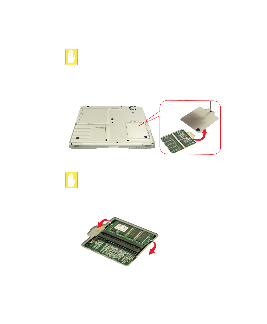
Installing a Memory Module
Handle a memory module carefully. Hold them only by the edges.
To install a memory module:
1. Turn the computer over so that the bottom faces up.
2. Using a screwdriver, remove the screw that holds the memory-module
compartment door in place.
3. Grasp the edge of the door and pull the door off the chassis.
Memory Module Precautions:
When removing the module, pull on the plastic portion of the connector slots
tabs only. Do not pull on the metal part of the tabs, this may damage the tabs.
4. Remove the installed module if necessary.
a. Pull the tabs on the connector slot outward slightly, until the edge of the
memory module pops up.
b. Hold the memory module by the edges and pull it forward out of the
compartment.
Using Options 81
Page 97
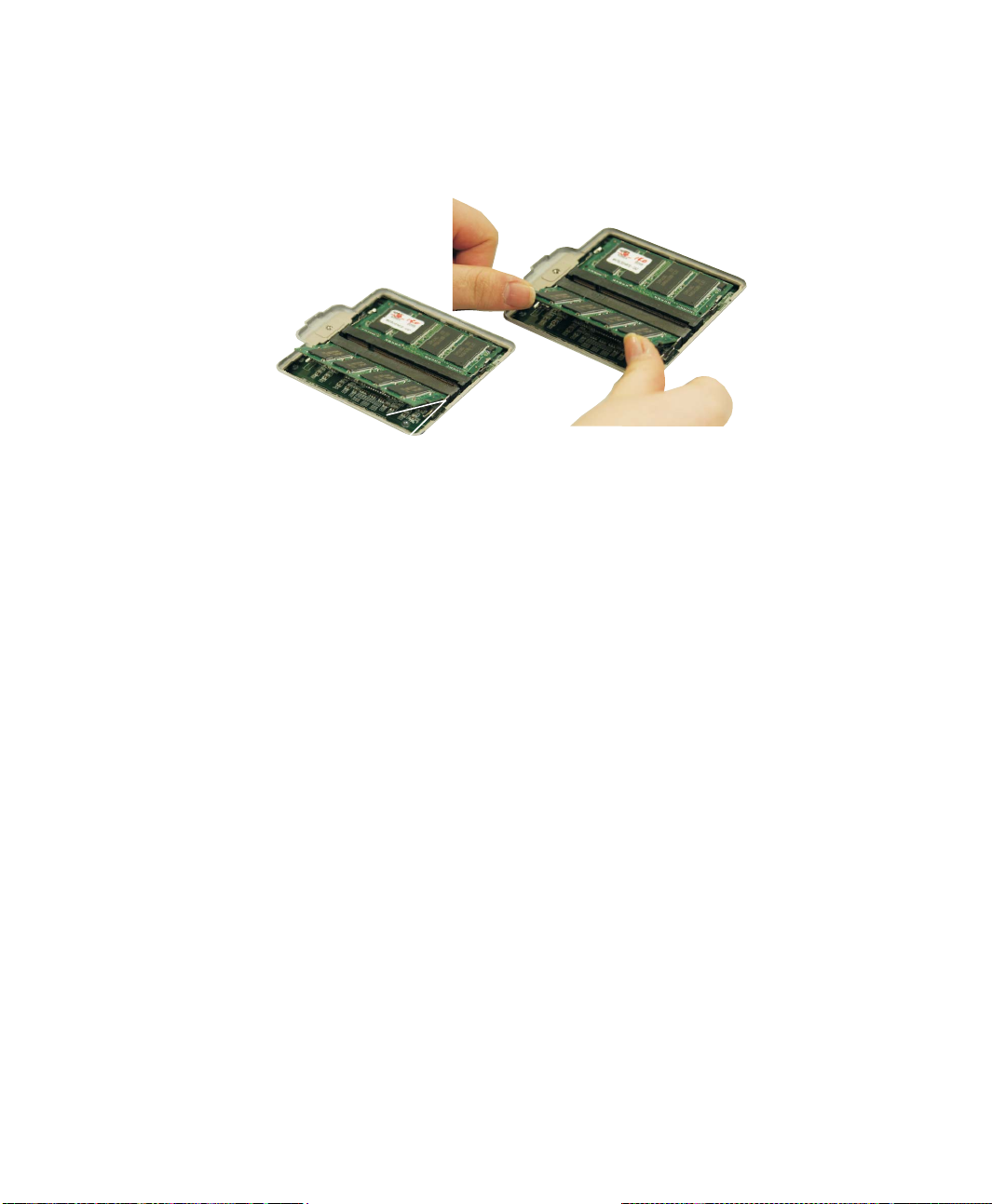
5. Align the connector on the memory module with the connector of the slot.
6. Push the memory module into the slot at a slight angle (~45
o
) until the connectors
are fully engaged.
o
45
7. Push down on the edge of the memory module until the module snaps into place.
8. Align the memory module compartment door with the compartment and push the
door down until it snaps into place.
9. Reinstall the screw you removed in step 2.
82 Users Manual
Page 98

FIR (Fast Infrared) Connection
FIR Technology Limitation
The transmitter and the receiver should be no more than 50cm apart.
System Setup
The system setup setting must be completed first in order for the option to
operate properly.
1. At startup, press <F2> to open System Setup.
2. Use <Right Arrow> to select the Advanced menu.
3. Highlight the I/O Device Configuration option with <Up Arrow> or <Down
Arrow> keys and press <Enter>.
4. Highlight the FIR port with the <Up Arrow> or <Down Arrow> keys.
5. Press <F5> until the option changes to Enabled.
6. Press <F10> to exit and save your changes.
7. Press <Enter> again to restart the computer.
Windows Setup
1. Right-click My Computer.
2. Click Properties, the System properties window pops up.
3. Click the Hardware tab then click the Device Manager button in the Device
Manager section.
4. Double-click the Infrared devices.
5. Double-click the IrDA Fast Infrared Port, the IrDA Fast Infrared Port properties
window pops up.
6. Click on the Advanced tab and set the device as follows.
• Select the “Infrared Transceiver A” in the properties section.
• Select the “Vishay TFDS-6500” in the value section.
7. Click OK.
Using Options 83
Page 99

Troubleshooting
Complete the following in the order presented until your system is functioning
properly. If all of the steps below fail then contact your local reseller for assistance.
Questions and Answers
Please see “Questions and Answers” on page 85. for assistance in correcting any
computer operational problems.
Check the Connections
Verify all of the power and peripheral cables are securely plugged into their sockets
and that your system and power supply is on.
Norton AntiVirus
Run Norton AntiVirus to insure a virus is not affecting your computer.
To run Norton AntiVirus proceed as follows:
Click Start > All Programs > Norton AntiVirus > Norton AntiVirus 2002.
Windows Help and Support
Run Windows Help and Support to find problem that may be affecting your
computer.
To run Windows Help and Support proceed as follows:
Click Start > Help and Support.
Reinstalling Software and Windows XP
If for some reason your system crashes you may corrupt your HDD, Windows
Operating system and/or some of your device drivers. If this is the case, use System
Recovery CD to reinstall OS and System Software CD to reinstall the corrupt device
drivers.
84 Users Manual
System Recovery Precaution:
Before you start restoring your windows operating system insure you backup
all data on your hard drive.
Samsung is NOT responsible for any data loss.
Page 100

Questions and Answers
This section provides information on possible problems, solutions and other references
for system use.
Windows Related
Q1 The system does not shutdown properly.
A When the system does not shutdown normally, press and hold the Power button
until the system manually shuts off. If the Power-Saving Mode is configured into
the Power button, press and hold for more than 4 seconds to shut the system off.
When the system is turned on after such manual shutdown, Scandisk will run to
check errors in the system.
Q2 The system freezes during program operation
A1 There is an error with the program currently being used. Press the <Ctrl>, <Alt>,
and <Delete> keys simultaneously and click and Task in the [Windows Task
Manager] window.
A2 There is an error with the Windows OS. Reboot the system by using the Power
button.
Display Related
Q1 The LCD screen is dim.
A Adjust the LCD screen brightness. Use the <Fn+Up Arrow>, <Fn+Down
Arrow> keys.
Q2 In DOS mode or with a screen resolution lower than 1024x768 pixels,
pressing the Fn+F2 key does not display the icon clearly.
A The screen image is extended across the LCD size when the screen resolution
setting is lower than 1024x768 pixels. If the icon appears unclear, it is because
the video chip does not support this function, but it does not affect the system
performance.
Troubleshooting 85
 Loading...