


Notices
No part of this publication may be reproduced, stored in a retrieval s ystem, or
transmitted, in an y form or by any means, mechanical photocopying, recording or
otherwise, without the prior written permission of the manufacturer.
The information within this manual is subject to change without notice.
The manufacturer shallnot be held liable for technical or editorial errors or omissions
contained in herein; nor for incidental or consequential damages resulting from the
furnishing, performance or use of this material.
Microsoft, Windows i s a registered trademark of the Microsoft Corporation.
Product na mes mentioned herein are for identification purposes only, and may be
trademarks and/or registered trademarks of their respective companies.
Macrovision Statement
If your computer has a DVD drive and an analog TV Out port, the following
paragraph applies:
This product incorporates copyrightprotection technology that is protected by method
claims of certain U.S. patents and other intellectual property rights owned by
Macrovision Corporation and other rights owners. Use of this copyright protection
technologymust be authorized by Macrovision Corporation,and is intended for home
and other limited viewing uses only unless otherwise authorized by Macrovision
Corporation.Reverse engineering or disassembly is prohibited.
Copyright 2000 All rights are reserved
Notices i

Important Safety Information
Safety Instructions
Your system is designed and tested to meet the latest standards for safety of
information technology equipment.However, to ensure safe use of t his product, it is
important that the safety instructions marked on the product and in thedocumentation
are followed.
Always follow these instructions to help guard against personal injury
and damage to your system.
i
Setting Up your System
Read and follow all instructions marked on the product and in the documentation
•
beforeyou operate your system. Retain all safety and operating instructions for
future use.
Do not use this product near water or a heat source such as a radiator.
•
Set up the system on a stable work surface.
•
The product should be operated only with the type of power source indicated on the
•
rating label.
Insure that the electrical outlet you are using to power your equipment is easily
•
accessible in case of fire or short circuit.
If your computer has a voltage selector switch, make sure that the switch is in the
•
proper position for your area.
Openings in the computer case a re provided for ventilation. Do not block or cover
•
these openings. Make sure you provide adequate space, at least 6 inches (15 cm),
around the system for ventilation when you set up your work area. Never insert
objects of any kind into the computer ventilation openings.
The computer product is equipped with a three-wire power cord to make sure that
•
the product is properly grounded when in use. The plug on t h is cord will fit only
into a grounding-type outlet.This is a safety feature. If you are unable to insert the
plug into an outlet,contact an electrician to installtheappropriate outlet.
If you use an extension cord withthis system, make sure thatthe total ampere rating
•
on the products plugged into the extension cord does not exceed the extension cord
ampere rating.
ii Users Manual

Care During Use
Do not walk on the power cord or allow anything to rest on it.
•
Do not spill anything on thesystem. The best way to avoid spills is to not eat or
•
drink near your system.
Some products have a replaceable CMOS battery on the system board. There is a
•
danger of explosion if the CMOS ba ttery is replaced incorrectly. Replace the
battery with the same or equivalent type recommended bythe manufacturer.
Dispose of batteries according t o the manufacturer’s instructions. If the CMOS
battery requires replacement insure that a qualifiedtechnician performs the task
When the computeris turned off, a s mall amount of electrical current still flows
•
through the computer. To avoid electrical shock, always unplug all power cables
and m odem cables from the wall outlets be fore cleaning the system.
Unplug the system from the wall outlet and refer servicing to qualified personnel if:
•
– The power cord or plug is damaged.
– Liquid has been spilled into the system.
– The system does not operate properly when the operating instructions are
followed.
– The system was dropped or the cabinet is damaged.
– The system performance changes.
Replacement Parts andAccessories
Use only replacement parts and accessories recommended by manufacturer.
To reduce the risk of fire, use only No. 26 AWG or larger
telecommunications line cord.
Do not use this product in areas class i fied as hazardous. Such areas
include patient care areas of medical and dental facilities, oxygen r ich
environments, or industrial areas.
Important Safety Information iii

Battery Disposal
Do not put rechargeable batteriesor products powered by nonremovable rechargeable batteries in the garbage.
Contact your customer service representative for information on how to dispose of
batteries that you cannot use or recharge any longer.
Follow all local re gulations when disposing of old batteries.
iv Users Manual

Regulatory Compliance Statements
United States Users
FCC Part 15
This device has been tested and found to comply with the limits for a Class B digital
device, pursuant to Part 15 of the FCC rules. These limits are designed to provide
reasonable protection against harmful interference in a residential installation.This
equipmentgenerates,uses, and can radiateradiofrequencyenergya nd, if not installed
and used in accordance with the instructions, may cause harmful interference to radio
or television reception. However, there is no guaranteethat interferencewill not occur
in a particular installation. If this equipment does cause interference to radio and
television reception,whichc an be determined by turning the equipmentoffandon,the
user is encouraged to try to correct the interferenceby one or moreof the following
measures:
Reorient or relocate the receiving antenna
•
Increase the separation between the equipment and receiver
•
Connect the equipment into an outlet on a circuit different from that to which the
•
receiver is connected
Consult the dealer or an experienced radio/TV technician for help.
•
Compliance Accessories: The a ccessories associated with this equipment are:
shieldedvideocable.Theseaccessoriesarerequiredtobeusedinordertoensure
compliance with FCC rules.
This device complies with P ar t15 of the FCC Rules. Operationof this product is
subject to the following two conditions: (1) this device may not cause harmful
interference, and (2) this device m ust accept any interference received, including
interference that m ay cause undesired operation.
Changes or modifications not expressly approved by manufacturer
couldvoid the FCC complianceand negate your authority to operatethe
product.
FCC ID: A3LS760
Regulatory Compliance Statements v

FCC part 68 (applicable to products fitted with USA modems)
This equipment compiles with part of the FCC rules. On the back of this equipment is
a label that contains,a mong other information,the FCC registration number and ringer
equivalencenumber (REN) for this equipment. If requested, this information must be
provided to the telephone company.
This equipment uses the following USOC jacks: RJ11C
An FCC complianttelephone cord and modular plug is provided with this equipment.
This equipment is designed to be connected to the telephone network or promises
wiring using a compatible modular jack whichis Part 68 compliant. See Installation
Instructions for details.
The REN is used to determine the quantity of devices which may be connected to
telephone line. Excessive RENs on the telephone line may result in the devices not
ringing in response t o an incoming call. In most, but not all a reas, the sum of RENs
should not exceed five (5.0). To be certain of the number of dev ices that may be
connectedto a line, as determined by total RENs, contact the local telephonecompany
to determine the maximum REN for the calling area.
If the terminal equipment causes harm to the telephone network, the Telephone
Company will notify you in advance that temporary discontinuance of servicemay be
required. But if advance notice is not practical, the telephone company will notify the
customerassoona s possible. Also, you willbe advisedofyourrighttofile a complaint
with the FCC if you believeit is necessary.
The telephone company may make changes i n its facilities, equipment, operations,or
procedures that could affect the operation of the equipment.If this happens, the
telephone company will provide advanced notice in order for you to make necessary
modifications to maintain uninterrupted service.
If troubleisexperiencedwith this equipment forrepairorwarrantyinformation, please
contact your local distributor or Samsung Electronics Corporation at (408) 544-5124.
If theequipmentis causingharmto the telephonenetwork,the telephonec ompany may
request that you disconnect the equipment unt i l theproblem is resolved.
The user must use the accessories and cables supplied by the manufacturer to get
optimum performance from t he product.
No repairs may be done by the customer.
Thisequipmentcannot be used on public coin phone serviceprovidedby the telephone
company. Connection to party line service is subject to state tariffs.
vi Users Manual

The Telephone Consumer Protection Act of 1991 makes it unlawful for any person to
useacomputeror other electronicdevice,includingfax machines,tosend any message
unless such message clearly contains in a margin at the top or bottom of each
transmitted page or on the first page of the transmission, the date and time it is sent and
anidentificationofthe businessorotherentity,orotherindividual sendingthe message
and the telephone number of the sending machine or such business, other entity, or
individual. (The telephone number provided may not be a 900 number or any other
number for which charges exceed local or long-distance transmission charges.)
In order to program this information into your fax machine, refer to your
communications software user manual.
Canadian Users
Radio Interference Regulations(ICES-003)
Thisdigitalapparatusdoes not exceedtheClass B limitsfor radionoiseemissionsfrom
digital apparatus as s et out in the radio interference regulations of Industry Canada.
Le présent appareil numérique n’é met pas de bruits radioélectriques dépassant les
limitesapplicables aux appareils numériques de Classe B prescrites dans le règlement
sur le brouillage radioélectrique édicté par Industrie Canada.
DOC notice (for products fitted with an IC-compliant modem)
The IndustryCanadalabel identifiescertified equipment.Thiscertificationmeans that
the equipment meets certain telecommunications network protective, operation, and
safetyrequirements.The Departmentdoesnot guarantee the equipmentwill operate to
the users’ s atisfaction.
Before installing this equipment, users should make sure that it is permissible to be
connected to the facilities of the local telecommunications company. The equipment
must also be installed using an acceptable method of connection. In some cases, the
inside wiring associated with a single-line individual service may be extended by
means of a certified connector assembly. The customer should be aware that
compliance with the above conditions may not prevent degradation of servicein some
situations.
To avoid electrical shock or equipment malfunction do not attempt to
makeelectricalgroundconnectionsby yourself. Contacttheappropriate
inspection authority or an electrician, as appropriate.
Regulatory Compliance Statements vii

Repairsto certifiedequipmentshould bemadebyanauthorizedCanadian maintenance
facility designated by the supplier. Any repairs or alterations made by the user to this
equipment, or equipment malfunctions, may give the telecommunications company
cause to request the user to disconnect the equipment.
Users should make sure for their own protection that the electrical ground connections
of the powerutility, telephonelines, and internalmetallic waterpipesystem, if present,
are connected together. Thisprecaution may be particularly important in rural areas.
The Ringer EquivalenceNumber(REN) assigned to each terminal device provides
an indication of the maximum number of terminals allowed to be connected to a
telephoneinterface.The terminationon an interfacemay consistof any combinationof
devices subject only to the requirement that the sum of the Ringer Equivalence
Numbers of all the devices does not exceed 5.
viii Users Manual

Laser Safety
All systems equipped with CD and DVD drives comply with the appropriate safety
standards, including IEC 825. The laser devices in these components are c lassified as
“Class 1 Laser Products” under a US De partment of Health and Human Services
(DHHS) RadiationPerformanceStandard. Should the unit ever needservicing,contact
an authorized service location.
Laser Safety Note:
Use of controls or adjustments orperformanceof proceduresotherthanthose
specified in this manual may result in hazardous radiation exposure. To
prevent exposure to laser beams, do not try to open the enclosureof a CD or
DVD drive.
Laser Safety ix

Power Cord Requirements
The power cord set (appliance coupler, flexible cord, and wall plug)you received with
yourcomputermeets the requirementsfor use in the countrywhereyou purchased your
equipment.
Power cord sets for use in other countries must meet the requirements of the c ountry
where you use the computer. For more information on power cord set requirements,
contact your authorized dealer, reseller, or serviceprovider.
General Requirements
The requirements listed below are applicable to all countries:
The length of the power cord set must be at least 6.00 feet (1.8m) and a maximum
•
of 9.75 feet (3.0m).
All power cord sets must be approved by an acceptable accredited agency
•
responsiblefor evaluation in the country where the power cord set will be used.
The power cord set m ust have a minimum current capacity of 7 A and a nominal
•
voltage rating of 125 or 250 volts A C, as required by each country’s power system.
The appliance coupler must meet the mechanical configuration of an EN 60 320/
•
IEC 320 Standard Sheet C13 connector, for m ating with applianceinlet on the
computer.
x Users Manual

Country-Specific Power Cor d Set Requirements
The requirementslistedbeloware applicableto the specific country listed:
Country
Australia EANSW 1
Austria OVE 1
Belgium CEBC 1
Canada CSA 2
Denmark DEMKO 1
Finland FIMKO 1
France UTE 1
Germany VDE 1
Italy IMQ 1
Japan JIS 3
The Netherlands KEMA 1
Norway NEMKO 1
Sweden SEMKO 1
Switzerland SEV 1
United Kingdom BSI 1
UnitedStates UL 2
Accrediting
Agency
Applicable Note
Numbers
Notes:
1. Flexible cord must be <HAR> Type HO5VV-F, 3-conductor, 1.0 mm²
conductor size. Power cord set fittings (appliancecoupler and wall plug)
must be ar the c ertification mark of the agency responsible for evaluation
in the country where it will be used.
2. Flexible cord must be Type SVT or equivalent, No.18 AWG. Wall plug
must be a two-pole grounding type.
3. Appliance coupler, flexiblecord, and wall plug must bear a "T" mark and
registration number in accordance with the Japanese Dentori Law.
Flexible cord must be Type VCT or VCTF, 3-conductor, 0.75 mm²
conductor size. Wall plug must be a two-pole grounding type with a
Japanese Industrial S tandard C8303 (15 A, 125V) configuration.
Power Cord Requirements xi

Using Your Documentation
Congratulations on your purchase of a notebook computer. Whether you are new to
using a portable computer or are an experienced user, this user’s m anual can help you
get the most from your computer.
Manual Documentation Conventions
Information Icons
Three icons and their associated messages appear in this manual. The information
icons are placed before the step/information they apply to:
A warning indicates the possibility of personal injury.
A caution warns you of possible damage to equipment or data.
A note informs you of special circumstances.
Keyboard Conventions
Keys that you need to press to perform certain functions are displayed in the manual
using a small graphic of the button. For example:
indicates the control key (Ctrl on the keyboard).
If you need to press two keys at the same time, the key names are shown joined by a
plus sign. For example:
+
means that you should press theAlt key and hold it and then press thePg Up key.
Using Your Documentation 1

CD-ROM Device Naming Convention
In many installation programs you will have to get a program from the CD-ROM
device. The program installation sequence assumes that the CD is drive d:\, however
this is not always the case. The name of the CD-ROM drive is the letter following the
letter assigned to yourlast HDD. For instance, if you have one HDD with two
partitions, the HDD is drives C: and D: and the CD-ROM drive is then drive E.
Touchpad Conventions
You may be asked to click or double-click on items on the display screen. As a general
note the touchpadactionsact much i n the same wa y as a wheel mouse any differences
are explained fully.
The object that needs to be clicked upon will be displayed in Bold text or shown in a
small figure such as the “Start B utton” shown on the right =>.
Table 1. Touchpad Click Conventions
Action Process
Click Depress the touchpad left button and release
Double-Click Quickly click the left touchpad button two times
If you are new to using co mputers, see “Glossary”. The “Glossary” explains general
computing terms that are used in this m anual and tells you about some of the
differences between notebook computers and desktop computers.
Almost all "Windows" programs will display the name/function of a
button or icon if you place the touchpad pointer on the item you want
information about.
Software UserDocumentation
Your computer is shipped from the factory with several software programs installed.
The s oftware may include its own online or printed documentation. Refer to the
documentation or the Help optionsin the software for more information.
The figures and illustrationsin this manual may not be identicaltothose
on your system.
2 Users Manual
Introducing Your Computer
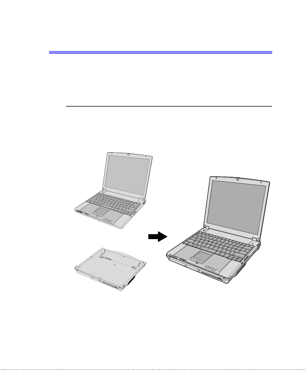
Your lightweight portable notebook computer includes many features to meet your
computing needs at home and/or on the road. The computer is a very slim lightweight
notebook computer with a docking station that has peripheral devices that allow it to
perform all of the functions of a desktop computer.
Where Everything Is
The following sections,PC Equipment Locations and Docking Station Equipment
Locations will explain the detailsof the notebook computer and the docking station as
well as other basic operations to dock and undock the computer.
Notebook Computer
+
Docking Station
Figure1. Notebook & Docking Station
Introducing Your Computer 3
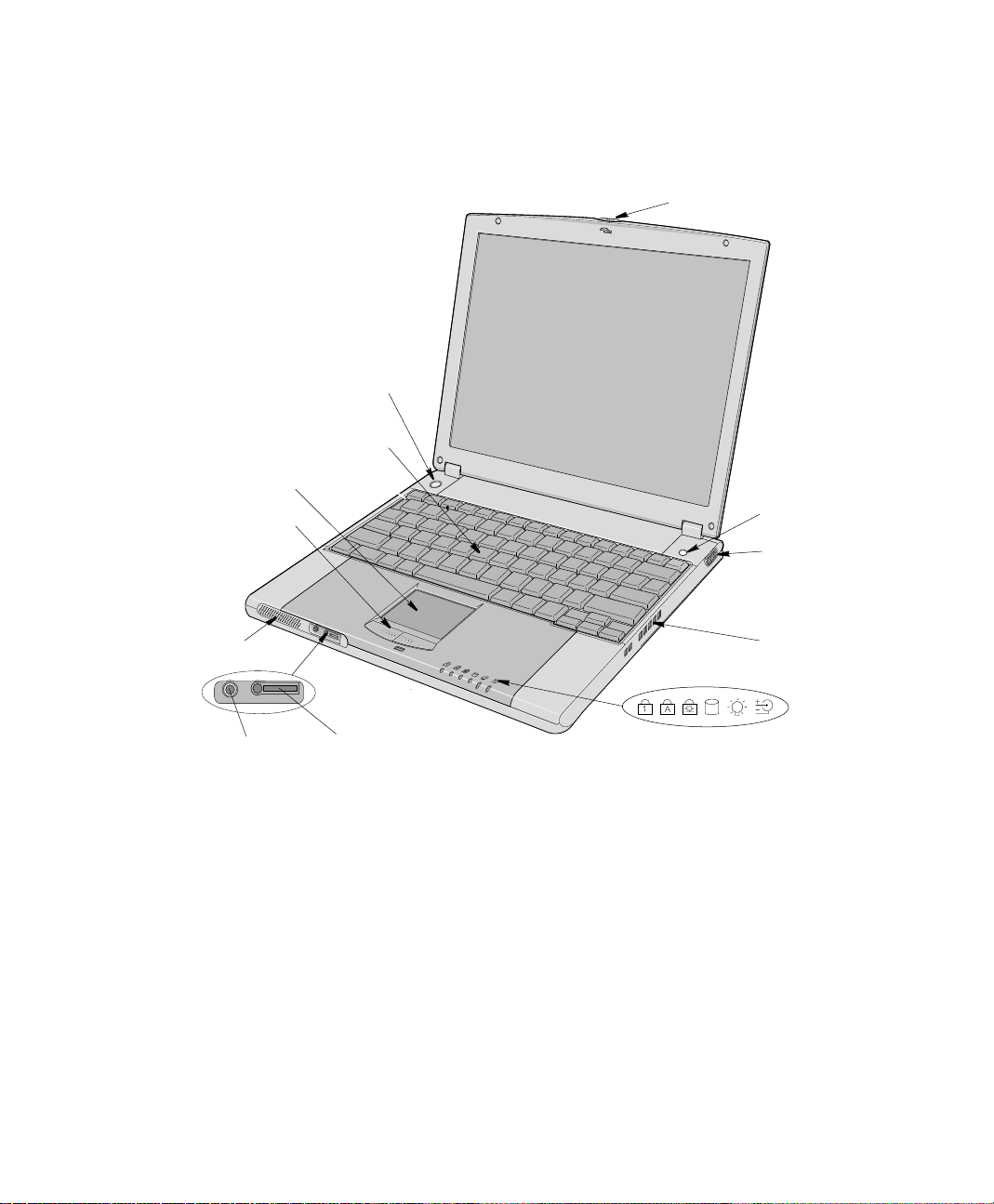
PC Equipment Location
The figures in this section show you the location of important items on the computer.
Power Button
Keyboard
Touchpad
Touchpad Buttons
LCD Latch
LCD Display
Internet Button
Video Port
Speaker
Microphone Jack
4 Users Manual
Headphone Jack
MP3 Controller Jack
Figure 2. Front/Right View of PC
Fan Vent
LEDs
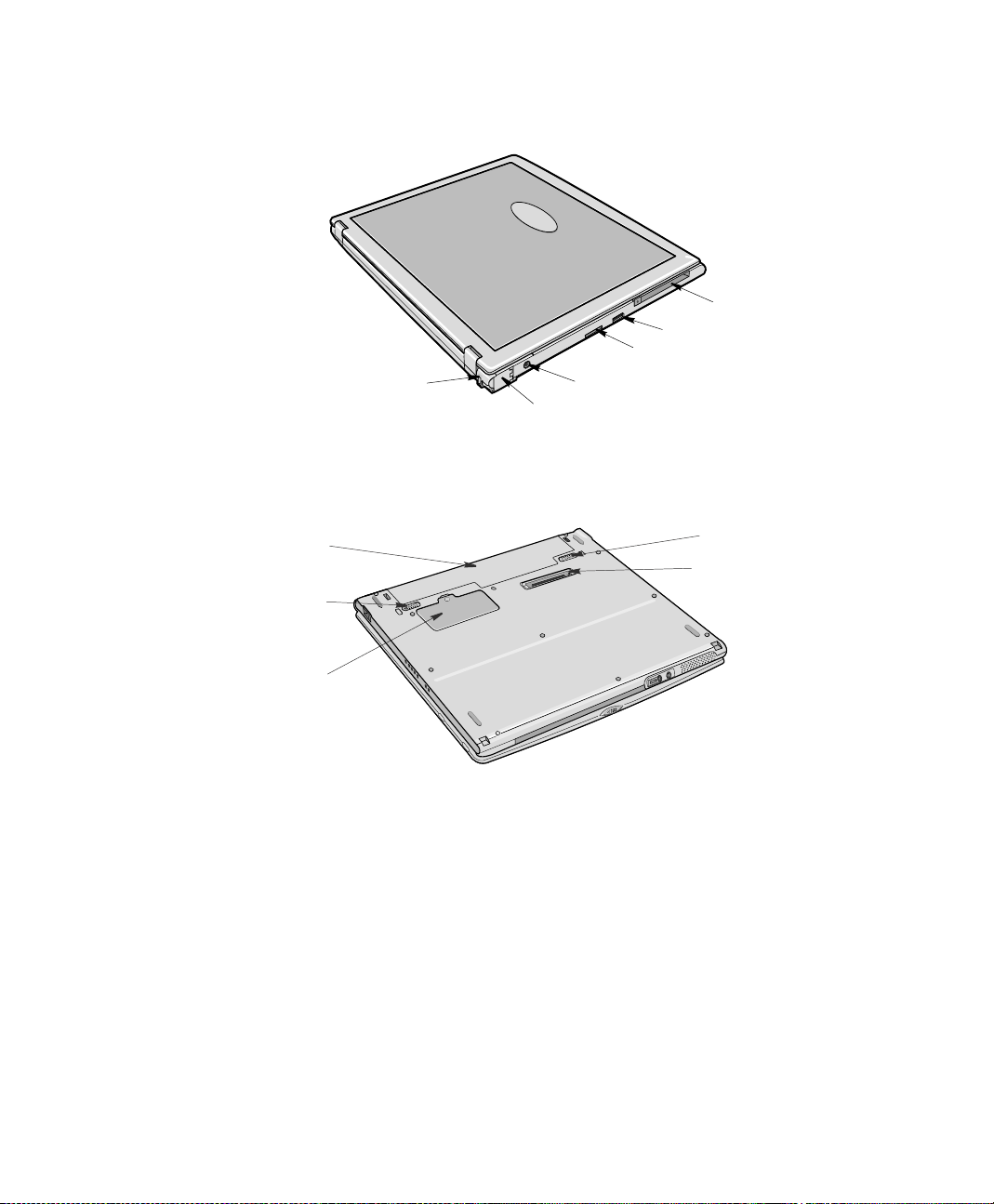
PC Card Slot
USB Port
LAN/Serial Port
Security Lock Port
DC-in Port
Modem Port
Figure 3. Back/Left View of PC
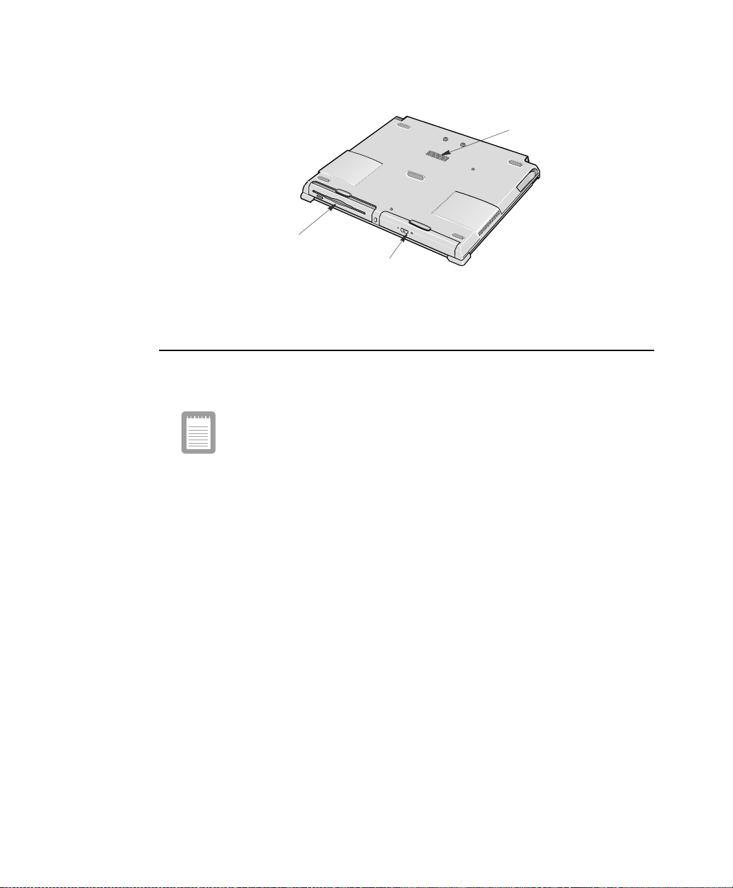
The figure below is the bottom view of the PC without the Docking Station attached.
Battery
Battery Latch
Memory Module
Compartment
Figure 4. Bottom View of PC
Battery Latch
Docking Connector
Introducing Your Computer 5
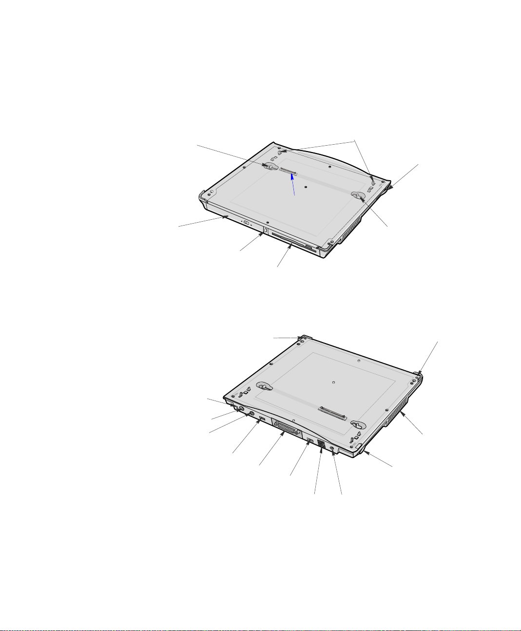
Docking Station Equipment Location
The figures in this section show you the location of important items on the docking
station. See “Using the Multi-Bays in the Docking Station” on page 33.
5.25"Multi-Bay
Release Latch
5.25 Multi-Bay
(CD/DVD Drive installed)
Eject PC B utton
Figure 5. Docking Station Front/Right/Top
Security Lock Port
(Composite)TV-OutPort
PS/2 Port
Docking Pins
Docking Release Lever
Docking Connector
3.5" Multi-Bay
Release Latch
3.5 Multi-Bay
(FDD installed)
Docking HookDocking Hook
Speaker
6 Users Manual
USB Port
Printer Port
USB Port
LAN Port
Figure6. Docking StationTop/Back/Left
DockingRelease
Lever
DC-in Port
Speaker
3.5" Multi-Bay Disk Drive
(FDD Drive)
5.25" Multi-Bay Disk Drive
(CD/DVD-ROM Drive)
Figure 7. Docking Station Bottom
Docking/Undocking your Computer
The docking station allows you to use this system a s a desktop PC.
Connect the AC adapter to the docking station when it is installed to the
computer.
Docking your Computer
You may dock your computer while the computer is off or on, however the preferred
and safer method is with the power off.
To install your computer into the docking station with the power off, completethe
following steps:
1. Disconnect the AC adapter from the system.
2. Place the front pa rt of a system on two hooks of the docking station.
3. Press the back part of a system until it clicks into the docking station fully.
Introducing Your Computer 7
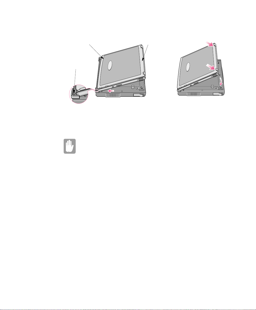
FrontoftheSystem
Docking Hook
Figure 8. Docking Sequence
Back of the System
Todockyourcomputerwith the power on simply placethe computer on the docking
hooks and press down on the area above t he keyboard.
Dock Change
When the docking station is connected properly then the "Dock Change"
messageshows.When the "Dock Change" messagedisappearsyou mayuse
the system. Press the system on both sides not the middle to ensure that the
docking connector is completely mated to the system.
Undocking your Computer
To re move your computer from the docking station with the power off, complete the
following steps.
1. Turn off the system.
2. Disconnect the AC adapter.
3. Grab the two docking release levers and pull themout until they click. The
4. Tilt the system up at the back.
8 Users Manual
computer will pop up approximately 1cm.
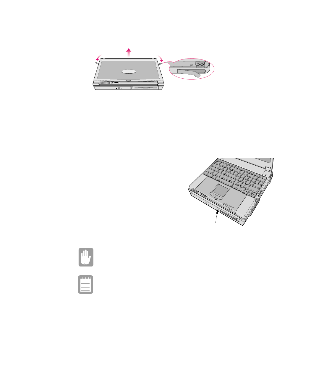
Figure 9. Docking Station Release Lever Operation
5. After tilting remove the system by sliding/lifting out toward the back of the
docking station.
6. Connect the AC adapter to the system.
To remove your computer from the docking station wit h the power on,
completethe following steps:
1. Press the Eject PC button on front of
the docking station for one second.
2. When “Dock Change” message
shows on the screen, pull the two
release levers outward until they
click and the computer pops up
approximately 1cm.
3. Remove the system.
4. AttachtheAC adapter to the system.
Eject PC Button
Figure 10. Undocking Computer (Power On)
Do not detach the computer if battery power is less than 20% power. The
system may crash and you will lose any unsaved data.
Use Start > Eject PC instead o f the Eject PC button i f the "Eject PC Button"
does not work and the dock change message is not displayed.
Introducing Your Computer 9
Using Your Computer for the First Time
This section gives you detailed information on using your c omputer for the first time.
Installing the Battery
The first step in using your notebook computer is to determine the normal use for your
computer. Two batteries (Standard and Long Life) come with the computer and both
go into the same s lot. The standardbatterymaybe used whether the computer is in the
docking stationor not. the long life batterymay only be used when the PC is not in the
docking station.
Ensure that both battery latches are slid fully toward the center of the
computer.
The long life battery cannot be used with the PC in the docking station.
Standard Battery
10 Users Manual
1
or
2
Long Life Battery
AC Adapter
Your computer runs on power f rom the battery in the computer or from an electrical
outlet.The firsttimethatyou use your computer, fully charge the battery using the AC
adapter, see Figure 11.
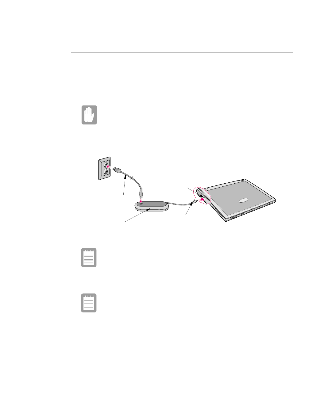
To attach the power cord complete the following:
Power Cords:
Many countries have differentpower cord configurations. Your computer
should be supplied with the correct one for your area. If not contact the
supplier.
1. Plug the AC adapter into the power connector on the back side of the computer.
2. Connect the power cord to the AC adapter and then to an el ectrical outlet.
DC-in Port
Power Cord
AC Adapter
Figure 11. Connecting the AC Adapter
The power connector may be plugged into either the computer or the
docking station. The preferred method when docked is to pl ug into the
docking station.
PowerConnector
The batterystarts chargingas soonas you plugthe powercordinto an electrical outlet.
The battery charges faster if the computer is turned off during charging.
Ensure you charge the battery fully the first time you use it.
See “Using the Battery” on page 46 for more information on using your computer’s
battery.
Using YourComputer for the First Time 11
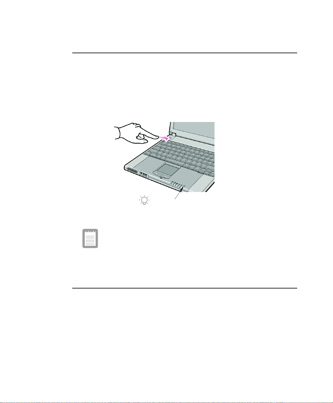
TurningOntheComputer
To turn on the computer’s power for the first time:
1. Slide the LCD latch, located on the front of the cover to the right.
2. Lift up the LCD display.
3. Press and then release the power button (Figure 12).
The power LED is on when the computer’s power is on.
Power LED
Figure 12. Turning on the Computer’s Power
Initial computer startup
The first time you start yo ur computer you will see the operating system
registration screen. There are several screens in the registration process.
Simplyreadeach screenand follow the simple directions.You must complete
thisprocess in order to use your computer. A tutorial is providedif you require
it.
Turning Off Your Computer
Prior to shutting down your computer ensure all of your data and current work are
saved. The shutdown process will ask if you wish to save your work, however by
saving your work first the shutdown process is quicker.
12 Users Manual
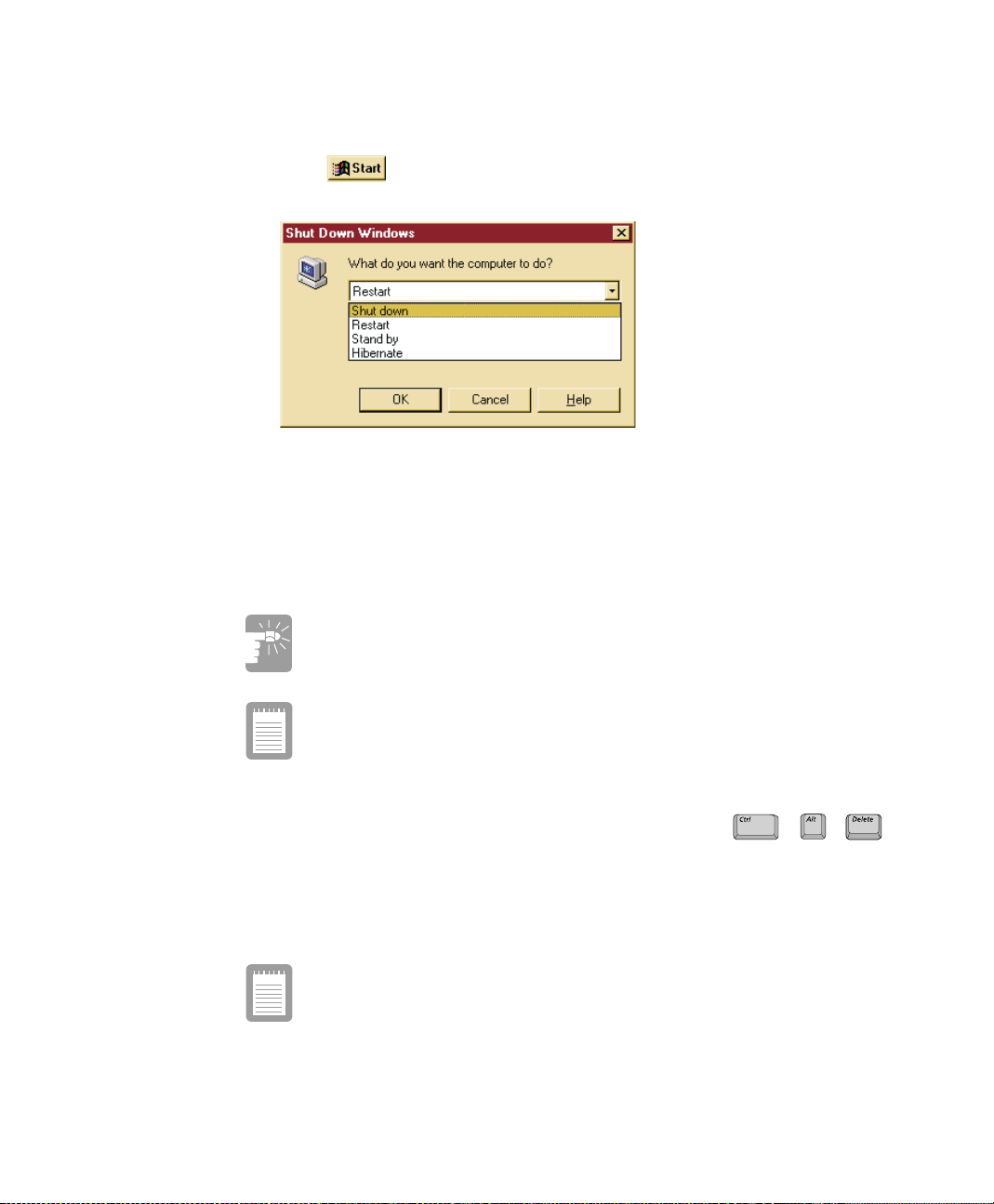
To turn off the computer, complete the following steps:
1. Click on the taskbar.
2. Click Shut Down.
Figure 13. Windows Shutdown Pop-up Window
3. Select Shut down.
4. Click OK.
If you need to restart your co mputer after software (re)installation or because it is not
responding select the Restart option in step 3 above instead.
If the system does not power off, then press and hold the power button
for over 4 seconds.
See “Using Power Management Options” on page 57.
System problems requiring a computer restart (Cold Boot):
Do not perform a cold boot unless your keyboardand touchpad have no effect
and you cannot perform a warm boot/software restart.
Whenyouperforma coldboot, you lose all data sinceitlastsavedto a storage
medium, i.e. Hard drive, Floppy disk.
You canalsoperformasoft boot by saving your filesandpre ssing
++
to pop-up the windows “Close Program” window. Click o n the Shut Down button.
You can perform a cold boot by pressing the power button for more than 3 seconds to
turn the computer off, waiting more than five seconds, and then pressing the power
button to turn the computer o n.
The power button has several functions other than just turning on and
off your computer, see “Using Power Management Options” on page 57.
Using YourComputer for the First Time 13

Using the LCD Display
This section will discuss using/changing the LCD display and its defaults:
The LCD display brightness adjustment is divided into 8 levels.
The key combination decreases LCD brightness.
•
The key combination increases LCD brightness.
•
+
+
The LCD display default settings are:
Level 6 when operating on AC power.
•
Level 4 when operating on battery power.
•
LCD Cleaning:
Cleaningthe LCD display should onlybe donewithasoftclothdampened with
denatured alcohol.
Even if you change the default LCD display brightness settings, the
defaults listed above will be restored once you power off and then back
on.
Notice: The limits of LCD manufacturing technology allow a maximum of 10
abnormal/bad pixels.
14 Users Manual

Tips for Using Your Computer
The following information helps you avoid potential problems as you use your
computer:
Do not try to disassemble your computer. Opening the system chassis
voids your warranty. Only an authorized manufacturerservice center
can replace or add any parts inside the chassis.
Follow all the instructions and cautions in your computer user documentation.
•
The LCD display has a polarized surface and can be damaged easily. To
•
prevent damage, avoid touching the LCD display screen.
Use only approved AC adapters, a uto adapters, memory m odules and other
•
options.
Becausea notebook computer is small and has restricted air flow around
•
components,it is more likely to overheat than a desktop computer. A fan inside
your computer runs when needed to help eliminate heat. Make sure the fan vent
on the right side of your computer is not blocked when you use the computer.
(See Figure 2 on page 4 for the location of the vent.) Occasionally ch eck the
vents and remove an y accumulateddust on the outside.
Avoid using or storing the computer in extremely hot or cold areas, such as a
•
car on a hot day. Keep the computer away from heatersand out of direct
sunlight.Exposure to e xcessive heat may damage computer components.
If you have left your computer in a hot place, let it cool down slowly to room
temperature (with the LCD panel open) before using it.
Do not remove the memory-module compartment door, or try to install a
•
memory module when the c omputer is on. (See Figure 4 on page 5 for door
location.)
(For information on installing a memory module, see “Installing a Memory
Module” on page 73.)
Set up your computer work area to avoid physical strain. Sit with your back
•
straight and supported by your chair. Adjust your chair or work table so that
your arms and wrists can remain in a relaxed position, parallelwith the floor.
Avoid bending or t wisting your wrists as you work. Your hands should “float”
slightly above the keyboard. Refer to a book on office ergonomics for more
information on setting up your work area.
Take frequent breaks from working at the computer to rest your eyes and
•
stretch your muscles.
Rememberto save your data files frequently and to makebackup copies of your
•
files.
Using YourComputer for the First Time 15
Travelling with Your Computer
Air Travel
If you are travelling by air, follow these tips:
Take the computer with you as carry-on luggage. Do not check the computer
•
with your baggage.
Allow the computer and disks to go through the X-ray security devices. Do not
•
hand-carry disks through the walk-through metal detectors, which can cause
loss of data.
Make sure that the battery is charged or the power cord is easily accessible.
•
You may be required to turn on the computer for airport security personnel.
Be prepared to turn offthe computer during take off and landing.
•
Locking your Computer
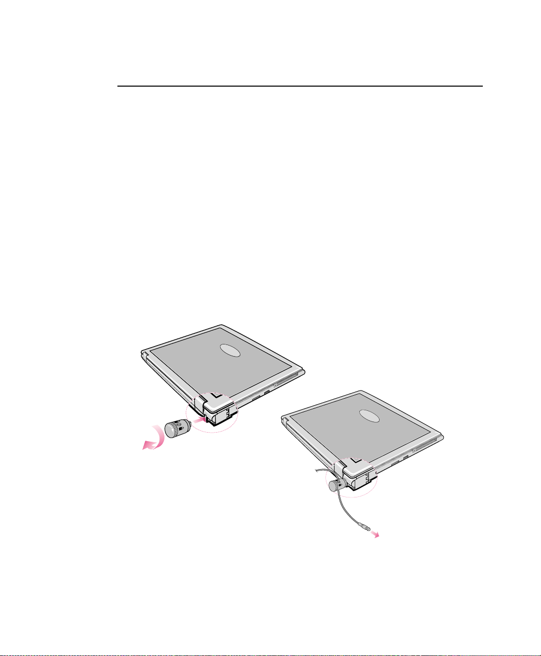
As a precaution when you aretravellingyou should keep your computer as safe as
possible. An option to do this is theSecurity Lock System. Follow the Security Lock
System manufacturers instructions for specificinstallation a nd use. The following
figure shows generally how to use the lock.
16 Users Manual
Figure 14. Security Lock System

Handling Spills
Sweet liquids leave a sticky residue that may jam the keyboard despite
your efforts to dry it.
Some liquids damage the polarized LCD screen. If your screen is
damaged, contact your authorized manufacturer’s service center for a
replacement.
Do not spill anything on your computer. The best way to avoid spills is to not eat or
drink around your computer. If you do spill something on your computer, turn it off
and unplug it immediately,then do the following:
If you spill liquid on the keyboard, drain as much of the liquid from the
•
keyboard as possible. Be careful not to let the liquid drip onto the LCD panel.
Allow the system to dry for several days before trying to use it.
If you spill liquid on an external keyboard or keypad,unplug it and drain as
•
much of the liquid as possible. Allow the keyboard to sit at room temperature
for a full day before trying to use it.
If you spill liquid on the LCD panel, clean it immediately with asoft cloth and
•
denatured alcohol. Do not use water, window cleaner, ac etone, aromatic
solvent,or dry, rough towels to clean it.
Using YourComputer for the First Time 17
Using the Keyboard
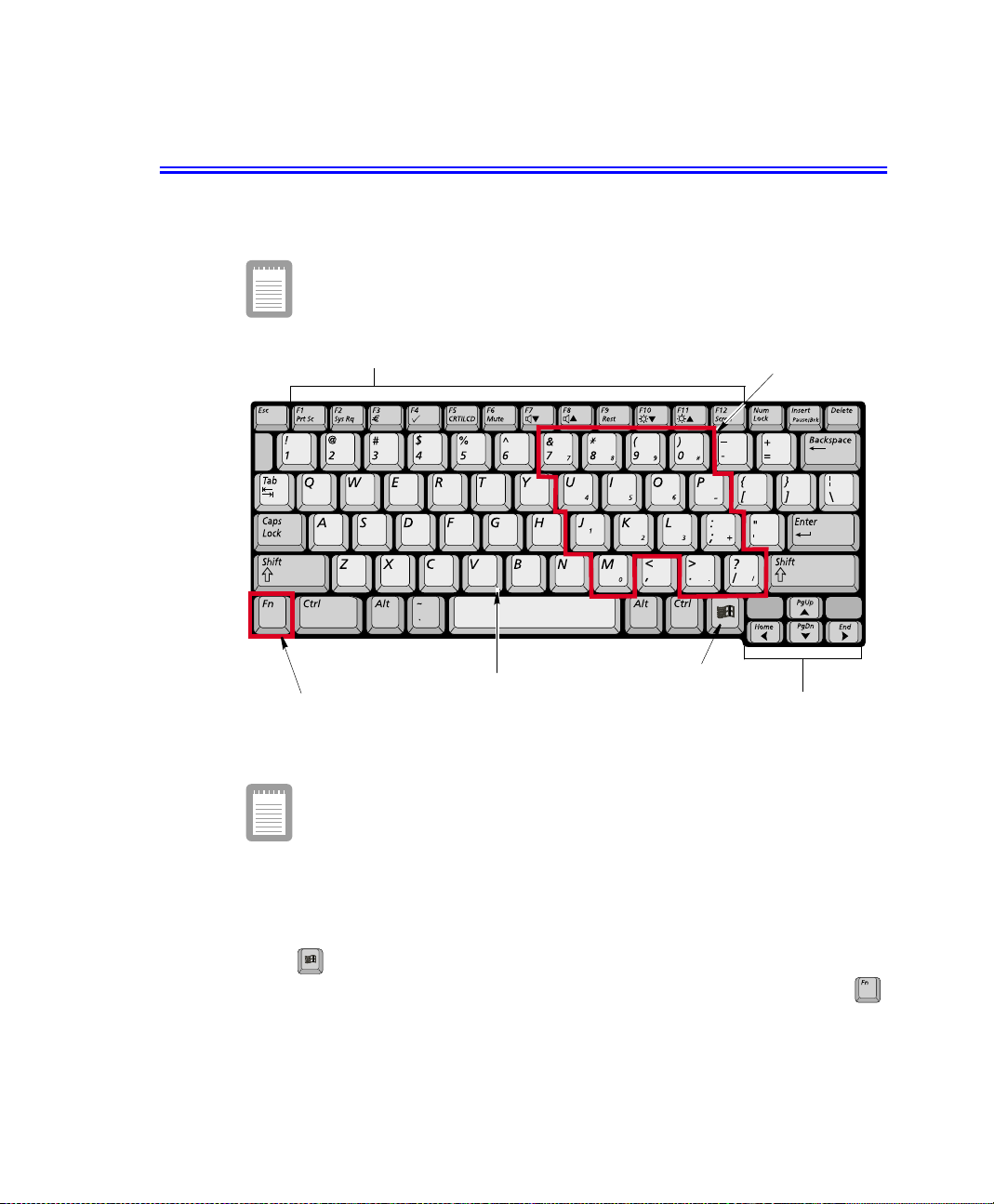
Your computer has an 81-key keyboard (Figure 15). By pressing designated key
combinations, you can haveaccess to all the key functions of a full-sized keyboard.
Keyboard configuration is different from one country to another,
however t he operation of the keys and key combinations remain the
same.
Function & Special purpose Hot Keys
Alphanumeric Keys
Function Key
Figure15. US Keyboard
Althoughthelayoutof the keys on your computer’s keyboardisdifferent
from that on a desktop computer’s keyboard, the keyboard feels like a
full-sized keyboard when you use it.
Windows Key
Embedded Numeric Keypad
Cursor/Screen Control Keys
The keys on the keyboard can be grouped into the followingcategories:
Full-sized Alphanumeric typewriter keys are arranged like a standard
•
typewriterkeyboard[QWERTY] and are used for text entry. The Windows key
opens Windows menus and performs other special functions.
F1 to F12 and the Cursor/Screen Control keys, when pressed together with
•
key, enable special functions.
18 Users Manual
The F1 to F12 keys are assigned to different functions depending on the
program in use, however the key is usually assigned to program
help.
Cursor and Screen control keys move the c ursor. They may perform other
•
functions, depending on your software.
Do not allow liquid to drip into the keyboard or you may damage the
keyboard.
To clean the computer keyboard, use slightly damp cotton swabs. Scrubthe keys and
the surface a round the keys.
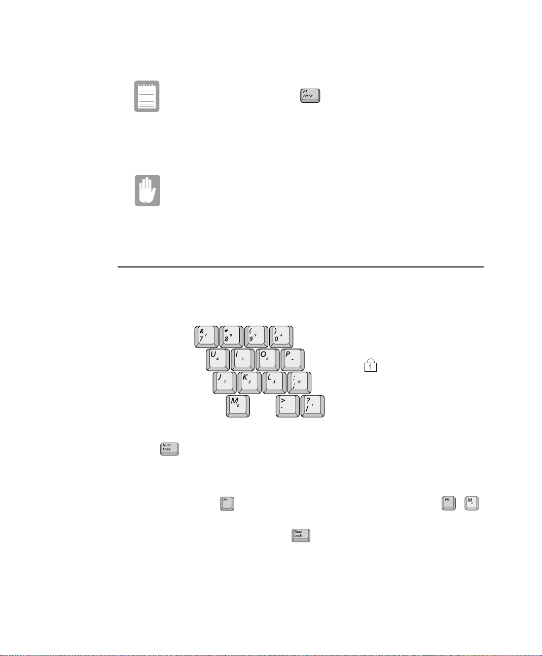
Using the Numeric Keypad
Your keyboard includes a numeric keypad, which is a group of keys that you can set to
type numbers and mathematical symbols, such as the plus sign(Figure 16). A number
or symbol on the right corner of each keypad key shows its nu meric function.
Num Lock LED
Figure 16. Numeric Keypad & Numlock LED
Press to turn on the embedded numeric keypad. The numeric functions of the
keypadareenabledand the Num Lock LED turns on. (See “Readingthe System Status
LEDs” on page 26 for thelo cation of the Num Lock LED.)
Whilethenumeric functionsa re enabled,youcantemporarily returnakeyto its normal
functionby pressing and the key. For e xample to type the letter m, press ,
+
this operation displays the letter m.
To turn the numeric keypad off, press again. The Num Lock LED turns off.
Using the Keyboard 19

Using Special Function Keys
The function key activates special functions when it is pressed in combination with
another keys. Table 2 shows the special key combinations.
Table2. Descriptionof Special Function Key Combinations
Key
Combinations
+
+
+
+
+
+
+
Key
Name
F1
PrtSc
F2
Sys Rq
F3 Euro key: This key combination can generate Euro Mark as
F4 Magic keyboard: Gives the user the ability to quick launch a program
F5
CRT/LCD
F6
Mute
F7 Volume down: Decreases the audio volume.
Key Function
Print screen: Takes a picture of the open screen, which you can
System request: Reserved for use in software programs.
CRT/LCD: Switches the display between the LCD, the external
Mute: Turns the audio output on and off.
paste into many graphics programs.
other Eurokey.
using the Magic keyboard key combination. Windows
Calculator is the default program.
monitor, and simultaneous display on both the LCD
and the external monitor.
+
+
+
+
+
+
+
+
+
20 Users Manual
F8
F9
Rest
F10 Brightness down: Decreases the LCD brightness.
F11
F12
Scroll
Home
PgUp
PgDn
End
Volume up:
Rest:
Brightness up:
Scroll:
Home:
PgUp:
PgDn:
End:
Increases the audio volume.
Puts the computer into Suspend mode. To resume
normal operation, press the power button. (See
“Power Management” on page 47.)
Increases the LCD brightness.
In some applications, sets the cursor-control keys to
scroll the page up or down while the cursor position
does not change. Pressing key combination again
turns off the scrolling function.
In some applications, moves cursor to the start of the
line.
In some applications, moves cursor up one screen, not
necessarily a full page.
In some applications, moves cursor down one screen,
not necessarily a full page.
In some applications, moves cursor to the end of the
line.

When you press a function key combination, the system sound may be
i
temporarily muted.
Internet Quick Start Button
Use the internet quick start button to start your connection to the internet just by
pressing one button.
Internet Quick
Start Button
Figure 17. Internet Explorer Quick Start Button
User Defined Keys (Magic Keyboard)
You may program the key combination to start any program you have
installed on your computer. By default the Windows calculator is assigned to the
Magic Keyboard key combination.
To reprogram the Magic Keyboard, follow the steps below:
1. Double-Click icon on the Windows taskbar or clickStart > Settings >
Control Panel.
2. Double-Click icon.
3. Select User Ke y from the drop down menu.
4. Use the Browse button to locate t he program you wish to assign to the Magic
Keyboard key combination.
5. Click on your program choice to select it.
6. Click OK.
+
Using the Keyboard 21

User Key
Figure 18. Magic Keyboard Program Interface
7. Click OK to close window and complete programming the Magic Keyboard.
You may also program the internet button to open the internet browser
program you wish to use.
22 Users Manual

Using the Touchpad
Your computer is equipped with a touchpad, which is an i ntegrated-pointing device
that is used to perform standard mouse functions (Figure 19). The touchpad is an
advanced and reliable pointing device that works with a touch of your finger.
Touchpad
Figure 19. Touchpad Operation
Touchpad Precautions:
Do not use sharp, magnetic or heavy items on your touchpad doing so may
cause damage.
Press on the touchpad gently. The touchpad responds to light pressure.
The following sectionswill basicallyexplain how to usethetouchpad.Table 3 liststhe
general a ctions associated with the touchpad.
Table 3.
Action Process Comment
Click Depress the touchpad left button and
Double-Click Quickly clicktheleft touchpad button
Click-Hold Depress the touchpad button and do
Right Click Depress the touchpad right button and
release
two times
not release
release
Touchpad
Touchpad buttons
Click Conventions
This will cause a process to begin
This will cause a process to begin
This is used to move/drag objects to new
locations
This is usually used to obtain information
about an object or start a process
PS/2 Mouse:
You may change the setup in Setup > Advanced M enu
Disabled preventsboththetouchpadand external PS/2 port from functioning.
Single mouse (default) enables the external PS/2 port or the touchpad, and
external PS/2 port has priority.Dual Mouse allows the use of both the
touchpad and PS/2 port.
Using the Touchpad 23

Double-Click/Tap
Selectthe window or icon bytappingonce on a touchpad. You can startprogram process
in the window by double tapping the touch pad quickly or you can use the touchpad
buttons.
Drag (Move)
To move a window to change the view on the desktop, compl ete the following:
1. Click the window title bar or icon in the bottom of the window which you want
to drag using the touchpad.
2. Press the left touchpad button and hold it.
3. Drag the window using the touchpad.
Cursor in
Windows Title Bar
Click theWindow
Title Bar and Hold
24 Users Manual
Drag your finger
to move the window
Figure20. Dragging a window
Area or multiple item selection:
The drag function may be used to select an area or multiple items in an area
byclickinginoneareaandthendraggingtocreateaselectionwindow.The
items inside the window will be selected.

Scroll
The touchpad has a scroll function. Scroll along the right edge of the touchpadto scroll
up and down. Scroll along the bottom edge of the touchpad to scroll right and left.
However, this function may not work in some programs.
Scroll Directions
Figure 21. Scrolling using the touchpad
Touchpad Buttons:
You can use the buttons below the touchpad in the same way you would use
standard wheel mouse buttons. For more information on these features and
other features supported by your mouse driver such as button assignment,
see the Mouse properties in the Control Panel.
Using the Touchpad 25

Reading the System Status LEDs
System Status LEDs show the status of computer functions.
Figure 22. System Status LEDs
Table 4. LED Functions
LED Name Function
Num Lock Changes a portion of the keyboard to a numeric keypad.
See “Using the Numeric Keypad” on page 19.
LEDs
26 Users Manual
Caps Lock Changes all alpha or letter input into capital letters.
Scroll Lock Scroll lock in certainsoftware.
HDD UsingHarddisk.
Power Green - System power on.
Battery Status Green - No battery pack installed/battery fully charged.
No changes occur to numeric and special keys.
Blinking - Standby mode.
Amber - Charging.

Connecting to the Internet
This section explains how to connect you to the internet. For program details on how
to establish the connection contact the Internet Service Provider [ISP]orsystem
administrator [SysAdmin].
Installing a Modem Cable
Before you can obtain information on the Internet or send e-mail you must verify t he
modem drivers are installed and connect the modem cable, See “Using the Modem”
on page 28.
To connect the modem cable. follow the steps below:
Figure23. Modem Cable Installation
1. Open the modem cable door located in the back left portion of the computer.
2. Plug the modem cable into the Modem port.
3. Contact your Internet Service Provider to obtain information required to make the
connection in your area.
4. After the cable is connected create a “Dialup” connection by clicking Start >
Settings > Dial-Up Networking.
5. Double-Click icon to pop up the connection wizard.
6. Follow the instructionsin provided in the Make New Connection wizard.
Connecting to the Internet 27

Using the Modem
Your Notebook computer will have a Modem/LAN installed in your computer.
Precautions Before Use
If you connect the modem to a digital phone line, the modem may be
damaged.
DOS support
WindowsMedoesnot support pureDOSmodeandthe modem doesnotsupporta DOS
box in Windows. So you can not use a communication application using in DOS.
Using the Modem on a PBX system
If you use a simple terminal program:
Type the “ATX3&W” or “ATX3” command as an initialization command.
If you use a Windows Communication Program:
Follow the instructions below.
1. Click Start > Settings > Control Panel.
2. Double-Click icon.
3. Click Properties in the General tabsection.
4. Check off “Wait for dial tone before dialing” check box in the Connection tab
5. Click OK to close the dialog box.
6. Click OK to close“Modem Properties”dialog box.
28 Users Manual
section.
MODEM Notes:
1. In the US due to FCC limitations,speeds of 53kbps are the maximum
permissible transmit power levels during download transmissions. Actual
data speeds will vary depending on line conditions.
2. In order to use the56Kfeature,be sure to checkifthestandardssupported
by the on-line service provider and the modem are identical.
3. If you use a PBX phone system, you can not connect using the 56K mode
due to line loss.

Installing a LAN Cable
Before you can obtain information on the Internet, send e-mail or transfer files to or
from another computer you must (re)install the LAN drivers, see “Windows Me LAN
Driver (Re)Installation” on page 85. There are two ways to hook up to a LAN. You
may plug directly into the back of the computer or us e a LAN cableadapter.
To install the LAN cable to the back of the computer simply plug in the cable in the
slot in the back of the computer or you may also use the LAN adapter cable to access
the LAN. Simplyplug the adapter cable into the LAN/Serial slot on the left side of the
computer.
To install the LAN cable complete the followingsteps:
1. Plug the LAN cable into the LAN port in the back of the computer or into the
portable LAN cable connector.
Figure24. LAN Cable Installation (Back/Left)
2. Contact your SysAdmin to obtain informationrequired to make the connection in
your area.
3. After the cable is connected create the connection by clicking on Start > Se ttings
> Control Panel.
4. Double-Click icon to pop up the network connection window.
5. If you require further assistance to connect to your n etwork, contact your
SysAdmin.
Connecting to the Internet 29

Portable LAN cable:
You may also connect to the LAN using the portable cable that plugs into the
port provided on the left side of the computer.
LAN/Serial Port
Portable LAN cable
Figure25. Using the Portable LAN Cable
30 Users Manual

Using the LA N
Configuring Network Environment
1. Complete the installation of the Network Adapter Driver.
2. Double-Click icon in the control panel.
3. Click Network Configuration tab, then ensure that the Samsung SEM-2100iL
MiniPCI LAN Adapter is installed.
Figure26. Installing the LAN Driver
4. Select TCP/IP-> Samsung SEM-2100iL M iniPCI LAN Adapter in the list of
network c omponents in the installed list.
5. Click Properties. The TCP/IP Properties window opens.
6. Click IP Address tab.
7. Select Specify an IP address and then enter your IP address and the appropriate
subnet mask. If you use a DHCP server, selectObtain an IP address
automatically.
8. Click Gateway tab.
Connecting to the Internet 31

9. Enter gateway address in the New gateway.
10. Click Add. If you use DHCP server, this process is not needed.
11. Click DNS Configuration tab.
12. Select Enable DNS.
Enter host name in the Host.
•
Enter domain name in the Domain.
•
Enter DNS server address in the DNS Server Search Order.
•
13. Click Add. If you use DHCP server, this process is not needed.
14. Click OK when you finish the TCP/IP set-up.
15. Click Add from the Network dialog box.
16. From the Select Network Component type dialog box, select protocol.
17. Click Add.
18. From the Select Network Protocol dialog box, select Microsoft in the
Manufactures list and then select IPX/SPX-compatibleProtocol.
19. Click OK.
20. Repeat steps 15 to 17. Select Microsoft in the Manufactureslist, and then select
NetBEUI.
21. Click OK.
22. In the Network window, click File an d Print Sharing. Select both check boxes,
23. Click Network Identificationtab, type in anything you wish to identify this
24. When you finish the network set-up, click OK from the Network dialog box.
25. Restart your c omputer to update the system.
32 Users Manual
then click OK.
computerin Computer Name, Workgroup, Computer Description.Keepin
mind that eachComputer Name is unique on a network.

Using the Multi-Bays in the Docking Station
Your computer includes the dockingstation that holds a 5.25" and a 3.5" device in the
two multi-bays.Below is a listing of the device types you may install in your docking
station.
The de fault system is purchased with CD/DVD-ROM and FDD devices.
5.25” Devices: CD-ROM drive DVD-ROM drive CD-RW drive
3.50” Devices: Zip (250Mb) drive 2nd HDD pack FDD
Changing Devices
This section will discuss changing the 5.25" and 3.5" devices.
Themulti-bayisthe portion ofthedocking stationwhe re you changedevices.See Figure
5onpage6.
Changing a 5.25” Device
To change from one 5.25” device to another simply follow the steps below (Figure 27).
5.25" Device
Figure 27. Changing 5.25" Device
1. Turn off the system.
2. Detach the system from the docking station.
3. Slide the 5.25” multi-bay latch toward the m iddle of the multi-bay.
4. The device w ill pop out approximately 2cm.
Using the Multi-Bays in the Docking Station 33

5. Remove the device.
6. Insert the new 5.25” device into the multi-bay until the multi-bay latch clicks.
Changing a 3.5” Device
The method of changing a 3.5” device is same as changing a 5.25” device except you
have to use 3.5” multi-bay latch instead of 5.25”s (Figure 28).
3.5" Device
Figure 28. Changing 3.5" Device
34 Users Manual

Using the Disk Drives
Using the Floppy Disk Drive
Your computer comes with a 1.44 MB, 3.5-inch, floppy drive.
To use a floppy disk in your computer, insert it into the floppy drive (Figure 29).
Figure 29. Inserting a Floppy Disk
Floppy Disk Eject Button
To remove a floppy disk, press the floppy disk eject button on the front of the floppy
drive.
To protect the data on your floppy disks, follow the manufacturers guidelines.
Using the CD/DVD-ROM Drive
Compact discs are designed so that you can easily insert one into the computer when
you need it, and then remove it.
DVDNotes:
You may also purchase an optionalCD/DVD device to view videos recorded
on the CD/DVD medium. You wi ll haveto installthe providedDVD software to
view the DVD Title.
Using theDiskDrives 35

1. Press the button on the CD-ROM or DVD-ROM drive, and the tray slides out. (Do
not lean on the tray; because it will not support much weight.)
CD/DVD drive precautions.
Do not place reflective objects in the disc slot because of possible hazardous
laser emissions.
Thelaserbeamusedinthis CD/DVD-ROM driveis harmfulto the eyes. Do not
attempt to disassemble the CD/DVD-ROM d rive. Refer se rvicing to your
authorized service center.
Do not touch the CD/DVD lens, doing so may damage the device.
CD/DVD tray fails to slide out
The tray may be stuck, in which case straighten out a paper clip, insert
it into the Emergency Eject hole in the front of the CD/DVD-ROM and push it
until the tray ejects.
CD/DVDLEDOn
A LED on the dr ive trayis on whenthe computer is reading from a CD. Do not
remove a disc when this LED is on.
Proper CD/DVD Handling Techniques.
To clean a CD/DVD, wipe from t he center outwards with clean and d ry cloth.
Remove the CD/DVD when the drive activity LED is o ff.
2. Insert a CD/DVD, label side up (or remove a disc, if you have finished using it).
3. Pushthetrayingentlytoclosethedrivetray(Figure30).
Install and/or start a CD-based program as you would run a program on a floppy disk.
See your operating system documentation for more i nformation on running programs.
36 Users Manual
Eject Button
Emergency Eject Hole
CD/DVD-ROM LED
Figure 30. Using the CD/DVD-ROM Drive

Working with PCMCIA (PC) Cards
By installing PC Cards, you can add functions to your notebook computer similar to
those found on add-in boards for desktop computers. Available PC Cards include:
Input/output, such as modem, network, video capture, and SCSI cards.
•
Storage, such as hard drive and flash memory cards.
•
Your computer includes the following PC Card support:
One PC-Card slot: You can install Type I or II cards in the slot.
•
CardBus hardware and software: CardBus enables the computer to use 32-bit
•
PCMCIA Cards. Windows Me supports 32-bit and 16-bit PC Cards.
Zoomed video: Both PC Card slots and the video chip on your computer
•
support zoomed video. When you install a zoom video PC Card slot, data can
be transferred directly from the PC Card to video and audio systems without
going through the m icroprocessor. Video conferencing and real-time
multimediadevices,such a s video cameras, are supported by zoomed video.
Maintaining PC Cards
To maintain your PC Cards, follow these guidelines:
Keep cards away from excessive heat, direct sunlight, and liquids.
•
Do not drop, bend, flex, or crush cards when handling.
•
Keep dust, oil, water, magnets, and static electricityaway from PC Cards.
•
When a card is not in use, carry it in its protective carrying case.
•
Some PC Cards include cables that extend from the back of the cards. Be
•
careful not to bend or put excessive strain on these cables.
Using PC Cards
You can install PC Cards while the computer is on.
To insert a PC Card into a slot:
1. Push the slot door in with the PC Card.
2. Alignthe card with a slot and insert the card into the slot until it locks in place. See
“Using PC Cards” on page 37.
Working with PCMCIA (PC) Cards 37

The eject button for the card slot operates in two steps, therefore to remove a PC Card:
1. Push the eject button once to pop it outward.
2. Push the eject button ag ain, then the card will be ejected.
Eject button
PC Card
InsertPC cardwithproduct
information facing up
Figure 31. Inserting a PC Card
Windows Me
WindowsMe automaticallyassignscomputerresources (such as communication ports
and memory addresses) to the PC Card installed in your c omputer.
To remove a PC Card from your computer if your operatingsystemis Windows
Me:
1. Click icon on the taskbar.
2. Select the name of the card you want toremove, and then click the Stop button.
3. PushthecardejectbuttononthesideofthePCCardslotwhenpromptedtodoso.
4. Pull the card out of th e PC Card slot.
38 Users Manual
Use the following procedures to r emove PC Cards, or you may lose data
that is being stored to a card.

Multi Media Functions/Equipment
Media Player
You can play video and audio CD files with the Windows Media Player, a s well as
watching TV, video and listening to the radio through internet. The on-board audio
hardware and software of your computer enable th e computer to play audio/video
compact discs. The instructionsto play a video CD-ROM are the same as the
instructions for t he audio CD below. If you wish to do so, you ca n attach external
speakers to the Headphone jack.
Playing a Audio/Multimedia CD-ROM
To play an Audio CD follow the instructions below:
1. Insert a compact disc into your CD-ROM drive.
2. Press the button on the CD-ROM drive to open the CD-ROM device.
3. Insert a CD, label side up.
4. Carefully push the tray in to close the drive tray. The Windows Media Player
button appears on the taskbar if not already there, and the m usic begins to play. If
the disk does not play click icon on the Windows task ba r then navigateto the
CD drive using the file open menu.
Display
Change Mode
Play List
Figure 32. Windows Media Player
Play List
StopButtonPlay Button
Volume Control
Multi Media Functions/Equipment 39

CD LED On
A LED on the dr ive trayis on whenthe computer is reading from a CD. Do not
remove a disc when this LED is on.
Removing the Audio CD
To remove the CD follow the instructions below:
1. Click on the Windows taskbar to open the Windows Media Player window, if
not already open.
2. Click Stop in the Windows Media Player window or simply close the Windows
media player. See Figure 32.
3. Pressthebutton on your CD-ROM drive. Thedrivet ray opens and you can remove
the CD from the CD-ROM drive.
4. For m ore information on playing compact discs, see the Help menu in the
Windows Me dia Player window.
40 Users Manual

Movie Maker
You can edit audio and video data using this Movie Maker that is included with
WindowsMe. It is also possible to m ake a slide show with each frame or picture.
To start the program:
Click Start > Programs > Accessories > Windows Movie M aker.
Tool Bar
Collections
Workspace
Figure 33. Windows Movie Maker
Please r efer to the on-line help manual to operate t he Windows Movie
Maker.
Monitor
Volume Control
Using the Keyboard
Changing the volume with your keyboard.
Use to decrease the volume or to increase the volume.
Using the Volume Control Icon
Double-Click icon in the active program tray. The Volume Control window pops
up. Use this window to adjust the volume. You can popup a simple volumeslider by a
single click icon.
+
+
Multi Media Functions/Equipment 41

MP3 Player
The flash memory size of the MP3 Player is 32 MB, but the memory size
could be different from system to system.
Your system has a MP3 player integrated inside the computer chassis. You can
download songs from internet and save them on your system. You can use the MP3
player to listen to music even though the system is powered off.
FF (Forward)
Play/Stop
REC/Erase
LCD
REW (Rewind)
Power slide bar
Off / Music / Voice
Equalizer
Preset: Classic/Rock/Pop
Ear-phone connector
Figure 34. MP3 Controller Top/Right View
REP (Repeat)
Repeat: repeat one MP3 file
All: repeat every MP3 file
Shuffle: mix the order of the file
VOL (Volume)
HOLD
Lock the MP3 controller buttons
except the Power slide bar.
42 Users Manual
Figure 35. MP3 Controller Bottom/Left View

Listening to a MP3 file
To listen to your MP3 files simply follow the steps below:
1. Make a new folder on your system hard drive to store your MP3 files.
2. Connect MP3 controller to its jack on front of a system.
Figure 36. Connecting MP3 Controller
3. Connect ear-phone to the MP 3 controller.
Ear-phones
Microphone
Figure 37. Headphone Hookup
4. Click Start > MP3 Loader > MP3 Loader.
Multi Media Functions/Equipment 43

Download Button
Flash Memory Used/Free
Indicator Bar
Figure38. MP3 Loader
5. Open the folder you saved the MP3 files on the hard disk. The files will be shown
in the middle part of the window in a similar manner to Windows Explorer.
6. Select files you want to save to the flash memory of MP3 Player.
7. Click .
You may also use the standard windows drag a nd drop method to move your files.
Repeat this step until you have downloadedall of your selectionsor you have run
out of memory.
8. Close the MP3 loader.
The MP3 player will not operate with the MP3 loader open. "PC" will be
displayed in the led window of the player.
9. Slide the Power Slide bar to Music mode. A musical note
icon will appear on
....
the LCD of MP3 controller.
10. Pre ss Play/Stop button to play MP3 files. The MP3 file number and the playing
44 Users Manual
time will be displayed on the LCD of the controller.
Refer to the on-line help of the program.

Voice Recorder
You can use the microphone attached to the ear-phone to record your voice or other
sounds into the MP3 Player.
Recording
1. Slide the Power Slide bar to Voice mode. A microphone ( ) icon will appear on
the LCD of MP3 controller.
2. Press REC/Erase button to record your voice. The track number and recording
timewillbeshownontheLCDoftheMP3controller.
3. Press REC/Erase button again to finish recording.
4. To listen to what you recorded, press Play/Stop button.
Delete Recording
1. Select a file (recorded file) from your MP3 controller that you wish to delete.
2. Press REC/Erase button for greater than 1 second. Next ‘ERASE’ message is
displayed and blinks on the LCD, it means that the MP3 Player is ready t o erase
what you have chosen.
3. When ‘ERASE’ message is blinking, pre ss REC/Erase button for greater than 1
second to erase the file.
If you are using MP3 Loader program, it is easier to erase the file by
deleting a file from flash memory.
Multi Media Functions/Equipment 45

Using the Battery
Your computer uses a smart rechargeable Lithium-ion (Li-ion) battery pack for power
when the AC adapter is not attached to an electrical outlet. The smart battery gives a
accuratemeasurem ent of the current battery capacity which helps extendoperating
time by enabling effective power management in operating systems that take
advantage of the accurate information supplied by the battery.
Charging the Battery
Your computer’s battery starts charging automatically when you connectthe power to
thecomputerand to an electricaloutlet.If thecomputeris off, thebattery chargesfaster
than if the computer’s power is on.
Approximate charging times for the Li-Ion battery are:
1.5 hours with the computer off (Standard battery) and 3 hours (Long Life
•
battery).
4 hours with the computer on (Standard b attery) and 8 hour s (Long Life
•
battery).
While the battery is charging normally, the battery Status LED on the computeris
amber (See “Reading the System Status LEDs” on page 26 for the location of the
battery Status LED). When the battery is fully charged, the LED changes to green.
When you use a new battery pack for the first time or use a battery after a long period
of storage, the initial battery life is shorter than normal. Normal battery life resumes
after a few discharge-recharge cycles.
Follow these rules for charging your battery:
46 Users Manual
A battery normally discharges power when not used for long periods of time.
•
Be sure to recharge the battery every two months when it is not in use.
Make it a practice to discharge your battery fully before recharging the battery.
•
This can help extend the life of the battery.
Do not attempt to charge the battery in temperatures of under
•
o
over 90
If you will not be using the computer for a long period of time (a month or
•
more), you should completely charge the battery. After you have done so,
remove the battery from the unit.
F(32oC
.)
50oF(10oC) or

All batteries eventually wear out and lose the ability to hold a charge.
You may need to replace your battery pack aftera year of average usage.
All batteries lose their charge if they sit unus e d for an extended time
period. When not used, battery can discharge fully in 2 to 3 months.
Increasing Battery Life
If youplanto use your notebookcomputer withoutthedockingstation,increasebattery
life using the following methods.
General Environment
Using the methods below you can increase battery life by as much as 1.5 times.
Detach the docking station.
•
Detach any unnecessary USB and PS/2 devices - (camera,mouse,keyboard
•
etc.)
Do not use any Multimedia programs - (Windows MediaPlayer, audio/video
•
CDs) unless absolutely necessary.
Adjust LCD Brightness
Reducing the LCD display brightness will reduce the power consumption of the
battery.However, if you requirethescreento be bright thecomputerwill automatically
reduce the brightness after 20 minutes of inactivity. The screen will be returned to
original settings when you resume your activities.
To reduce the LCD display brightness use the key combination.
+
Power Management
Tochangethe time untilyourcomputer goesintoreducedpower modes,usethe system
power management function.
1. Click Start > Settings > Control Panel.
2. Double-Click PowerOptions.
The power optionspanel enables you to reduce the time until your computer goesinto
standby m ode for example. See “Using Power Management Options” on page 57 for
instructions on how to use this battery saving tool.
Using the Battery 47

Battery Calibration
Calibrating your battery once a month is one of the recommended methodsof
increasingyour computer’sbatterylife. To calibratethebatterycompletethefollowing
steps:
Calibration Notes:
You should start the battery calibration process with afully charged battery,
battery status LED is green. The power meter may not show 100%.
Beforeyoucommencethebatterycalibration process you should fully charge,
then f ully discharge and finally fully recharge the battery again.
1. Disconnect the AC power adapter after turning off the system.
2. Restart your computer and press to enter BIOS setup.
3. Using the arrow keys, highlightBattery C alibration in the Power menu.
4. Press to start calibration process. The calibration usually takes 2 to 3 hours
depending on the current battery charge.
5. When the calibration process is complete, recharge the battery fully.
Safely Using the Battery
Follow these guidelines to safely use the battery:
Turn off yourcomputer and unplug it if you acciden tally:
•
48 Users Manual
– Expose the e quipment to liquid.
– Drop, jar, or damage the computer.
Use only approved battery chargers.
•
Do not disassemble the battery, heat it above 212° F (100° C), or burn it. The
•
battery used in this computer may cause a fire or chemical burn if mistreated.
Your computer's rechargeable battery may be considered hazardous waste.
•
If you replace your battery with a new one:
– Keep the old battery out of the reach of children.
– Dispose of the old b attery promptly.
– Makesure that you follow all local requirements when you dispose of the old
battery.

Removing the Battery
Your computer comes with the battery pack inserted in the computer. To remove the
battery from the computer:
1. Turn the computer’spower off and close the LCD display panel.
2. Undock the computer if docked. See “Docking/Undocking your Computer” on
page 7.
3. Turn the computer over so that the bottom of the unit is facing up.
4. Slide the locking battery latch to the unlock position.
Locking Battery Latch
Battery Latch
Figure 39. Removing the Battery Pack
5. Slide and hold the remaining battery latch outward and slide the battery out of the
compartment.
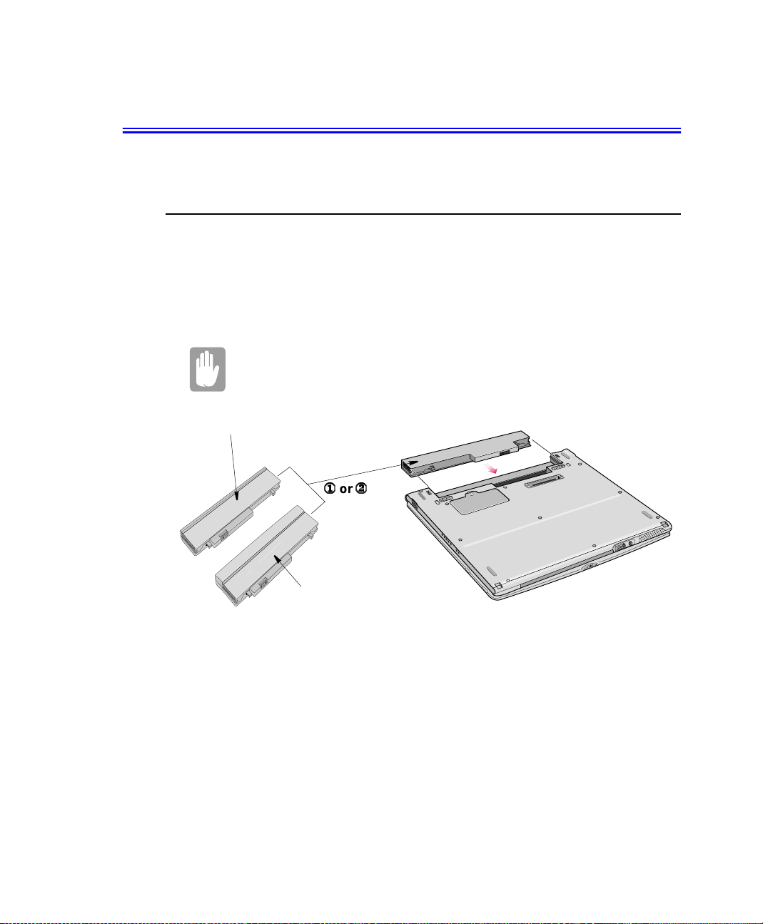
Installing the Battery
To install the battery pack, follow the steps below:
Insert the battery into the battery compartment. Ensure the correct
orientation so that the battery fits in its slot properly.
1. With the computer’s power off, close the LCD panel and turn the computer over
so the bottom of t he unit faces up.
2. Slidethe battery intothebatterypack into thecompartment(Figure40). Ensure the
battery is fully inserted into the compartment.
Using the Battery 49

3. Slide the battery pack latches toward the center of the computer. Make sure the
locking battery latch is in the lock position.
Locking Battery Latch
Figure 40. Installing the Battery
Monitoring the Battery Charge
Battery life is affected by factors such as the power-management settings in System
Setup, the applications you use, and the brightness settings of the LCD. Undernormal
usage, the battery charge lasts approximately3 hours for standard battery (undocked),
1 1/2 on standard battery (docked) and approximately 5 hours for the long life battery
(undocked).
50 Users Manual
Battery life estimates are subject to variation. The actual life of your
battery may be less than t he estimates given in the manual.

Power Meter
The Power Meter displays the charge of the batteries and the current source of
computer power, AC or batteries. You m ay monitor the battery charge or usage by
using the “Power Meter”. To access the power meter click icon on the task bar or
click Start > Control Panel > Power Opti o ns > Power Meter tab.
Figure 41. Power Meter
Youmayalso checkbatterycharge bymoving thecursor tothe icon, a smalldialog
box will display the % of charge.
Battery Warnings
If the battery charge is low (about 10%) you have approximately 5–10 minutes of
battery life left. You should:
Save your work and.
•
Connect the power cord the computer or turn off the computer and install a
•
fully charged battery.
You c an adjust the battery alarm features by using the operating systems power
management program (Control Panel > Power management in Windows Me).
If you cannotrun your computer from the battery and the battery will not c harge when
you attach the power cord, the problem may be that:
The battery temperature i s below 50° F (10° C) or over 90° F (32° C). If you
•
think the battery temperature is too hot or too cold, turn off the computer,
remove the battery, and let the battery reach room temperature. Then try
charging the battery again.
The battery is defective. Replace the battery with a new battery.
•
Using the Battery 51

Using System Setup
The System Setup program enables you to configure your computer hardware and set
security and power-savings options. The settings you choose a re stored in batterymaintained CMOS memory that saves the information e ven when the computer’s
power is turned off. When your computer is turned back on, it is configured with the
values found in this memory.
Run System Setup if you get a message prompting you to run the program. You may
also want to run System Setup, particularly the first time you use your computer,to set
the time and date, use security or power-management features, or alter the settings of
other features.
Your computer’s version of System Setup may not include all the f ields
listed here or may include additional fields. Field names and order of
appearance can vary according to the version of the BIOS (basic input/
output system) on your computer.
Starting System Setup
To start System Setup,turn on your computer and then press and hold until the
System Setup screen appears.
The topof theSystemSetupscreen has a menu bar with the selectionslisted in Table 5.
Table5. System Setup Menus
Menu Function
Main Changes the basic system configuration.
Advanced Configures advanced features on your computer.
Security Enables security features, including passwords and backup
Power Configures power-management features.
Boot Specifies the order of boot devices and configures boot
Exit Specifies how to exit System Setup.
and virus-check reminders.
features.
To open the menu you need to use, use the left or right arrow keys to select the menu
name.
Table 6 lists the keys you can use to navigate through System Setup.
52 Users Manual

Table 6. System Setup Navigation Keys
Navigation Key Function
Displays the General Help window.
Exits the current menu.
or
or
Selects different menus. Pressing the ESC key at the Main
menu brings you to the Exit menu.
Moves the cursor up and down between fields.
Moves the cursor forward through the cells for a highlighted
field. If the field has only one cell, the Tab key moves the
cursor down to the next field.
Scrolls backwards through the options for the highlighted field.
Scrolls forward through the options for the highlighted field.
Sets the parameters for the current menu to their default
values.
Sets the parameters for the current menu to their previous
values.
Executes commands or opens a submenu.
UsingSystem Setup 53

Changing Booting Priority
The Boot menu in System Setup enables you to select the booting device and to set
booting options.
Boot Device Priority field enables:
You to select the order in which the c omputer attempts to boot from different devices.
The field has four options:Diskette Drive, Removable Devices, Hard Drive, and
ATAPI CD/DVD-ROM Drive.
To change the booting device priority, choose the device positions by completing
the following:
1. At startup, press t o open System Setup.
2. Use to select theBoot menu.
3. Press in the Boot Device Priority field.
4. Highlight the option with keys.
5. Use keys until the option moves up or down in the list of options and
the number 1, 2, 3, or 4 appears beside the option.
6. Press to return to the Boot menu.
Thedefaultsettingis1.Diskette Drive,2. Removable Devices, 3. Hard Drive, 4. ATAPI
CD/DVD-ROM Drive.
7. Press togototheexitmenu.
8. Select E xit Save Changes, press .
9. Press again to restart the computer.
or
If you want to start the system using a bootable CD, change the ATAPI
CD-ROMDrivetobethef irst priority and make surethatAutois set in the
Type field of the Secondary Master Submenu at Main page.
or
54 Users Manual

Using System Security
This section describes the security options provided with your computer.
System Passwords
The computer provides t wo levels of password security: administrative-level
(supervisor)and user-level (user). Eitherpasswordprevents unauthorizedaccessto the
computer. The supervisor password enables full access to all System Setup fields. The
user password enables full access to only theSet User P assword and Password on
boot security fields and read access to all other System Setup fields.
If m ultiple users have access to the computer (such as in a network environment), a
supervisor password can prevent unauthorized access to certain security options.
Choose the type of password security that is appropriate for your work. If you want to
set a user password, you must set a supervisor password first.
If You Forget Your Password
It is very important that you do not forget your password. If you do, you cannot a ccess
your system. Write your password down and keep it in a safe place. If you do forget
and cannot find the written note, you will have to contact the resellerofyour computer
and possibly take or send it in to them so that you can access the computer again.
Creating a Password
To createa password follow the instructions below:
1. At startup, press t o open System Setup.
2. Use to select theSecurity menu.
3. Use to select Set Supervisor Passwo rd or Set User Password.
4. Press . The Set Password dialog box appears.
5. Type a password of up to seven characters.
Precautions for Password Ent ry:
You can enter letters or numbers, but you cannot use the function keys, such
as the Shift key. Your computerdoes not distinguish between capitalized and
lowercase letters in your password. As you type the password, the cursor
moves but your password does not appear on the screen.
Using System Security 55

6. Press after you have typed your password. The computer prompts you to
reenter your password for verification.
7. Type your password again and press . A message a ppears telling you that
the changes have been saved.
8. Press again to return to the Se cur i ty menu.
9. Press togototheExitmenu.
10. Select Exit Saving Changes,press .
11. Press again to restart the computer.
Deleting a Password
To delete the password follow the steps below:
1. At startup, press to open System Setup.
2. Type your password when prompted and press .
3. Use to select theSecurity m enu.
4. Use to select Set Supervisor Passwo rd or Set User Password.
5. Press . The computer prompts you to enter the current password.
6. Press . The computer prompts you to enter a password.Do not type
anything.
7. Press . The computer prompts you to re-enter the password. Do not type
8. Press . A message appears telling you that the changes have been saved.
9. Press again to return to the Security menu.
10. Press togototheExitmenu.
11. Select Exit Saving Changes,press .
12. Press again to restart the computer.
56 Users Manual
anything.
To enable the prompt, select the option
field in System Setup.
Enabled
in the
Password on boot

Using Power Management Options
Your computer includes Power Management options that can help the battery charge
last longer and extend the life of the battery. Power-management options will slow
down or shut off system components when the components are not being used.
Power management may slow down system performance. Your computer runs fastest
with the power cord attached, when power management is disabled.
In the next sections, basic and advanced methods of power management willbe
discussed.
Intel SpeedStep
There are two methods to change the Intel SpeedStepTMsetting, they are explained
below.
TM
BIOS Interface
Intel SpeedStepTMwillcontrol the CPU speed on your systemaccordingto thekind of
power supply as part of power saving management.
To use this function, your system must me et the conditions below:
Intel SpeedStepTMsupporting CPU
•
Application for SpeedStepTMfunction
•
BIOS Support
•
To start or verify Intel SpeedStep
1. Start your computer and press to enter BIOS setup.
2. Go to System Power m enu
3. Select the Intel(R) SpeedStep
Performance: The CPU runs at high speed regardless of the type of power
•
supply.Battery life is the shortest.
Battery: The CPU runs at low speed regardlessof the type of power supply.
•
Battery life is the longest.
Automatic: The CPU speed is changed according to the type of power supply.
•
(It is recommended you select this option)
Disabled: Disables this function
•
TM
is operational complete the following:
TM
field a nd select one of the following options:
4. Press to save and exit system setup
Using PowerManagement Options 57

Task Bar Interface
You m ay change the Intel SpeedStepTMsetting by double clicking on the icon on
the task bar. This will open the Intel(R) SpeedS tep
TM
technology popup window.
The following will explain each of the above numbered items.
1. This optionwill allow automaticor“Ask me before automatically changing” CPU
speed c hanges based on the power supply source.
2. Each power supply option has a drop down windowand when you click on the
arrow the drop down selector appears, displayed in n u mberabove. These
options allow the user to set operation of the CPU based on the power supply
source.
3. These are the available options for each type of supplied power.
TM
4. TheIntel(R) SpeedStep
that are self explanatory.
technology[Advanced] popup windowhas3 options
58 Users Manual

Basic Power Management Schemes
This section discusses the basic schemes of power management when the computer is
operating on battery power or usi ng AC power.
Standby vs. Hibernation
Standby unlike hibernation mode does not store unsaved information on your
hard disk;it's stored only in the computer memory. If there is an interruption in
power, the information is lost. So before putting your computer on standby,
you should save your files.
Changing Devices:
Do not change devices while in standby or hibernate modes.
To enter the power management window complete the following:
1. Click Start > Settings > Control Panel.
2. Double-Click icon to display thePower Options Properties window.
3. Click the Power Schemes tab to display the basic power management options.
4. Selectthe timethatyou wish each of the following actionsto occur inBatteryand
AC power mode.
•
Turn off the monitor.
•
Turn off the all hard disks.
•
System standby mode.
•
System hibernation mode.
Using PowerManagement Options 59

Power Schemes Tab
Figure 42. Power Options Properties - Power Schemes
Turning off the monitor and HDDs will save a substantial battery power, therefore
when in battery only mode select the shortest time practical.
,
Hibernate Mode (Power Management or Manual Method)
When hibernation is used, your computer turns off and when you power up again,
everythingis restoredexactly as youleft it—includingprograms and documentsyou
may not have saved or closed. Everything in me mory gets saved to the HDD, and
the monitor and hard disk get turned off.
Frequent Interruptions:
If you experience frequent interruptions, you might also consider putting your
computer into automatic hibernationaftera specified number of minutes using
the power management options.
,
Standby Mode(Power Management or Manual Method)
5. Click OK to set your power management options and close the window.
60 Users Manual
Standbyis used mainly for conservingbatterypower in your notebook computer. It
also gives you the benefit of getting right back to yourwork without waiting for the
computer to restart. Standby turns off your monitor and hard disks, placingyour
entiresystem in a low-power state. When you returntoyourco mputer, restoresyour
desktopexactly as you left it. It is recommended th at youdonotenterstandby mode
with less than 20% battery power.
The manual <Fn + F9> key combination will not work to go into Standby
orHibernatemodes while youareplayinga multimedia programorusing
the USB camera

Advanced Power Management Schemes
This section discusses the advanced power management schemes. There are two
buttons that you can use to manually conserve power.
To enter the power management window complete the following:
1. Click Start > Settings > Control Panel
.
2. Double-Click icon to display thePower Options Properties window
3. Click the Advanced tab to display the advanced power manag ement options.
Advanced Tab
ButtonProgramming
Windows
Figure 43. Power Options Properties - Advanced
4. Select the mode (Standby/Hibernate/Power Off) that you wish to assign to the
Power button and/or Sleep key.
The "Sleep" key is assigned to the key combination.
See “Basic Power Management Schemes” on page 59 for meaning of
Standby and Hibernate modes.
+
5. Click OK to set your power management options and close the window.
You can return to normal operation after you have used one of the “Power
Management” buttons by quickly pushing and releasing the Power button.
Using PowerManagement Options 61

Installing a New HDD
This section discusses installing a new HDD and other basic HDD operations.
Installing/Reinstalling a HDD
To installa new HDD you must contact your local servicerepresentative.He will
do the phy sical change of the drive. You should complete the instructions below
before you go to the s ervice center.
See the information below before you install your HDD:
•
Back up data files of your old hard drive.
•
For system boot with CD-ROM, under the Boot menu in System setup, set
Bootable CD Check to Enabled and set Boot Device Priority is ordered starting
from the [DVD/CD-ROM].
When you are ready to install the new HDD u se the Recovery CD-ROM to install the
device driver.
Using FDISK Utility
To use the FDISK utility:
1. Set the system boot with CD-ROM, press to boot with “Safe mode command
2. Operate Fdisk.exe, type A:\>fdisk.
3. Press Enter.
4. When Do you wish to enable large disk support (Y/N)...? shows.
5. Select Y and press Enter.
6. Select 1. CreateDOS partition or Logical DOS Drivefield in [FDISK Options].
7. Select Create PrimaryDOS Partition field in [Create DOS Partition or Logical
8. Press Enter to start creating Primary DOS Partition.
9. Finish the Fdisk by pressing .
62 Users Manual
prompt only”.
DOS Drive].

10. Display the HDD information using #4 in t he FDISK menu. verify the size of the
HDD partition.
11.
Press the power button to reboot the system.
Formatting the HDD
To format the HDD completethe following:
1. Boot system by CD-ROM.
2. Operate Format.exe,type‘A:/formatc:/s’ and press Enter
3. Warning message saying all the data will be removed shows, typeY
with Format (Y/N)?
4. Type the drive la bel (if one is desired) and press Enter.
and press
Enter
.
.
(Re)Installing Windows and Device Drivers
Use System Recovery CD to (re)install OS and System Software CD to (re)install
device’ drivers.
The System Recovery CD is used to (re)install the OS and
Software t o a new HDD
or recover from a system crash.
System
for
Proceed
Installing a New HDD 63

Video Features and Configuration
Your computer includes a TFT LCD or active-matrix display. The capabilities of the
screen plu s the video drivers installedon the computer determine the quality of the
image your LCD can display.
The following sections describe the display capabilities of your computer.
Adjusting the LCD Display
You may wish to adjust the LCD (Liquid-Crystal Display) when you begin using your
computer.ATFT(Thin-FilmTransistor) LCD doesnot requirea djustment for contrast
because the contrast is set to remain at maximum.
To adjust the LCD:
•
Press to decreasethe display brightness.
•
Press to i ncrease the display brightness.
+
+
64 Users Manual

Resolutionand Color Depth
z
- Display supported
5
- Display Supported except for DVD
X - Display not supported
Use either LCD or CRT when using the DVD player but not both.
LCD Only
CRT
R
e
f
Color
r
256 Color
16 bit
32 bit
CRT Only
R
e
f
Color
256 Color
16 bit
32 bit
r
640X 480 800 X 600 1024 X 768
e
s
h
R
a
t
e
Optimal Default Optimal Default Optimal Default
z z z z zz
z z z z zz
z z z z zz
640X 480 800 X 600 1024 X 768 1280 X 1064 1400 X 1050 1600 X1200
CRT
e
s
h
R
a
t
e
Optimal Default Optimal Default Optimal Default Optimal De fault Optimal Default Optimal Default
z z z z z z z z z z zz
z z z z z z z z z z zz
z z z z z z
x x x x
Dual Monitor (LCD & CRT)
CRT
640X 480 800 X 600 1024 X 768
e
s
h
R
a
t
e
Optimal Default Optimal Default Optimal Default
z z z z zz
z z z z
z z
Color
256 Color
16 bit
32 bit
R
e
f
r
z
z
z
Video Features and Configuration 65

Dual View(Using the LCD and CRT as 1 Display)
256 Color
CRT
R
LCD
640 X 480
800 X 600
1024 X 768
e
f
r
640 X480 800 X 600 1024X 768 1280 X 1064 1400 X 1050
e
s
h
R
a
t
e
Optimal Default Optimal Default Optimal Default Optimal Default Optimal Default
z z z z z z z z
z z z z z z z z
z z z z z z z z
16 bit Color
CRT
R
LCD
640 X 480
800 X 600
1024 X 768
e
f
r
640 X480 800 X 600 1024X 768 1280 X 1064 1400 X 1050
e
s
h
R
a
t
e
Optimal Default Optimal Default Optimal Default Optimal Default Optimal Default
z z z z z z z z
z z z z z z z z
z z z z z z z z
32 bit Color
CRT
R
LCD
640 X 480
800 X 600
1024 X 768
e
f
r
640 X480 800 X 600 1024X 768 1280 X 1064 1400 X 1050
e
s
h
R
a
t
e
Optimal Default Optimal Default Optimal Default Optimal Default Optimal Default
z z z z
z z z z
x x x x
z
x x x x
z
x x x x
Configuring Display Features
x x
x x
x x
x x
x x
x x
The following sections describe how to configure the display settings on your
computer.
Selecting a Monitor Type
When you attach an external monitor to your computer, Windows Me automatically
selects display settings for it. If you wish, you can adjust the display settings by
selecting a monitor type:
1. Click Start > Settings > Control Panel.
2. Double-Click icon. The Display Properties window a ppears.
3. Click the Settings tab. The Settings screen appears.
4. Click the Advanced button. The Advanced Properties screen appears.
5. Click the Monitor tab.
66 Users Manual

6. Click Change.TheUpdate Device Driver Wizard screen appears.
7. Click Next.
8. Select Display a list of all the drivers in a specific location, so you can select
the driver you want radio button.
9. Click Next.
10. Select Show all hardware radio button.
11. Select the manufacturer and model setting that matches your external monitor.
Your computer has an intelligent video chip set that automatically
matches your LCD panel resolution and frequency when an external
monitor is not present.
12. Click Next.
13. The UpdateDeviceDriver Wizardscreen appears showing the driver location of
the device you haveselected.
14. Click Next.
15. Follow any prompts that appear on the screen.
Changing Color Depth and Resolution
To change the colour depth and resolution of your LCD or external monitor:
1. Click Start > Settings > Control Panel.
2. Double-Click icon. The Display Properties window a ppears.
Video Features and Configuration 67

3. Click the Settings tab. The Settings screen appears.
Display Properties - Settings
Color Palette
Figure 44. Display Properties Window
Resolution Slider
4. To change the colour d epth, click the arrow next to Color palette and select the
colour depth you want.
5. To change the resolution,click anddragthe sliderunder theScreenarea until you
select the resolution you want.
6. Click OK.
7. Follow the prompts that appear on the screen.
68 Users Manual

Using the TV-Out Port
This feature is only available with Windows Me. Using the TV-out port, a compatible
TV or other compatible display devicecan be connected and an image displayed. No
Audio is transmitted through the TV-Out port. To check if and how your TV displays
the TV-out signal, see the documentation included with your TV.
Concurrent enabling of the LCD and TV is not supported. Therefore it is
recommended either the TV or LCD is used. While TV is ON, pressing
+
disables
TV-Out
To enable TV-out:
1. Connect the TV to the TV-Out port u sing an appropriate cable.
2. Enter System Setup and under the Advanced menu, set TV Out Mode to the
appropriate standard for your TV. (Default is NTSC, if you need to change go to
BIOS setup).
3. Reboot your computer.
4. Click the Start > Setting s > Control P anel.
5. Double-Click icon. The Display Properties window a ppears.
6. Click the Settings tab. The Settings screen appears.
.
7. Click the Advanced Properties button. The Advanced Properties screen a pp ears.
8. Click the S3DuoVue tab. The systemwill now try to detecta TV connected to the
TV-out port.
9. Put a tick in the box under the TV symbol if it is detected.
If the TV symbol is greyed out then the system has not detected a TV,
check that the TV standard in the System Setup is set correctly and that
the TV is turned on a nd connected properly.And you can not use TV-out
port in DOS m o de.
10. Click OK.
11. Follow the prompts that appear on the screen.
Video Features and Configuration 69

Using Duo View Mode
Single View mode is used to be the basic display method until now which displays
same view on all the display devices connected to a system. WhileDuo View mode is
the“Extendedscreen mode” supportedinWindows Me, which displaysseparate views
on each display devices connected to a system.
The default setting on your system is Single View mode.
Setting Duo View Mode
To set Duo View mode on your system:
1. Connect peripheral display device such as monitor or T V to your system and s tart
the system.
2. Select Start > Settings > Control panel.
3. Double-Click icon. The Display Properties window a ppears.
4. Click the Settings tab. The Settings screen appears.
5. Click the second monitor among two monitor pictures.
6. When ~ Do you want to enable this monitor?message appears, then select Yes.
7. Click OK.
To confirm whether the system is set properly with Duo View mode:
1. Open Display properties and click Settings tab.
2. Place the cursor on the first monitor picture and click and hold over a second, a
3. The m onitor displaysdigit number 1 is the primary monitor and number 2 is the
70 Users Manual
number1
the second monitor picture and click and hold over a second, then digit number2
will be shown on the second actual monitor screen.
secondary monitor.
InWindowsexplorer, theprogramis displayedontheprimary monitor,if you can
drag it to the secondary monitor, then Duo View mode is now working properly.
willbe shown on thefirstactualmonitorscreen.And place the cursor on

Figure 45. Dual View - Display Menu
The secondary monitor has a display of 256 colors (color depth) a nd 640x480 pixels
(resolution)at first. The color depth and resolution of primary/secondary monitors are
separately changeable.
To reset the system to SingleViewmode:
1. Start Display properties.
2. Click Settings tab.
3. Click the second monitor among two monitor pictures.
4. Uncheck Extend my Windows desktop onto this monitor.
5. Click OK.
Figure 46. Computer in Duo View Mode
Using Duo View Mode 71

Using Options
Youcanorderthe followingoptionsfor your Notebookcomputer from yourauthorized
reseller:
An extra AC adapter.
•
A battery pack. [Standard or Long Li fe size]
•
An upgraded hard drive. Optional hard drivesare available to fit in the hard
•
drive compartment or the 3.5" multi-bay of the docking station.
64,128and 256 MB SDRAM memory m odules that enable you to upgrade your
•
computer’s memory to a maximum of 320MB.
A CD-ROM drive module. [5.25" Multi-bay]
•
A DVD-ROM drive module. [5.25" Multi-bay]
•
A CD-RW drive module. [5.25" Multi-bay]
•
A Zip 250 Mb drive. [3.5" Multi-bay]
•
The options that are available may change periodically. Contact your reseller for
updated information on current and new options.
Memory Module
You can increase system memory by installingan optional64,128or 256 MB memory
module.
Before You Install Memory
Take the following precautions when installing a m emory module:
72 Users Manual
To prevent personal injury and damage to the equipment, follow the
precautions listed here before installing a me mory module.
Before you remove the memory module compartment door, turn off the
•
computer,unplugthe power cord, and remove the battery. Also, disconnect any
peripheral devices.
Before handling a memory module, discharge any static electricity by touching
•
a grounded surface or using a grounding wrist strap.

Do not insert objects with conductive material, such as metal screwdrivers or
•
graphitepencils, into the memory-module compartment.
Be careful in handling the metal plate of the memory door.
•
To avoid possible system problems, use only an approved memory
module in your computer.
Installing a Memory Module
Handle a memory module car efully. Hold them only by the edges.
To installa memory module:
1. Turn the computer over so that the bott om faces up.
2. Using a screwdriver, remove the screw that holds the m emory-module
compartment door in place. (Figure47).
Figure 47. Removing the Memory Module Compartment Door
3. Grasp the edge of the door and pull the door off the c hassis.
Memory Module Precautions:
When removing the module, pull on the plastic portion of the connector slots
tabs only. Do not pull on the metal part of thetabs, this may damage the tabs.
Using Options 73

4. Remove the installed m odule if necessary.
a. Pull the tabs on the connectorslot outward slightly, until the edgeof thememory
module pops up.
b.Hold the memory module by the edges and pull it forward out of the
compartment.
5. Align the connector on the memory module with the connector of the slot.
6. Pushthememory moduleintotheslot at a slightangle untiltheconnectors are fully
engaged (Figure 48).
Figure48. Installing a Memory Module
7. Push down on the edge of the memory module until the module snaps into place.
8. Align the memory module compartment door with the compartmentand push the
door down until it snaps into place.
9. Reinstall the screw you removed in s tep 2.
10. Turn on the computer and perform a complete POST to check the memory
integrity.
74 Users Manual

Troubleshooting
If you ever have d ifficulty running your computer, follow these steps:
1. Consult the following sections for adviceon how to h andle system problems.
2. If steps 1 do not help you to resolve the problem, contact your reseller.
3. Refer to warnings, cautions and notes within applicable portion of this manual.
4. Refer to “Windows” and other “Program” manuals as applicable.
Operating Problems
This section tells you what to do if you have problems running your computer. If any
problem persists after you take corrective action, contact your reseller for assistance.
The computer does nothing when you tur n it o n.
Has the battery run down? Connect the power cord to get power and recharge the
battery. Try turning on the computer again.
Some of the letter keys type numbers instead of the indicated letters.
IstheNumLock LED on? If so, the numeric keypad on the keyboard is active. To
return the keypad keys to typing letters, press .
Battery power se ems to run out faster than expected.
Ifyouarerunningthe computer from the battery ratherthanthepowercord, make
sure that you set the Idle Mode fieldinSystemSetuptoOn. This setting enables
the microprocessor and the hard drive to slow down when the computer is not
busy.
Certain software programs “hang” during operations when there is no
interaction with the keyboard or peripheral devices.
Your computer may be in Suspend or Rest mode. Tap the touchpad to resume
from Suspend or press the power button to resume from rest.
A PC Card does not work correctly.
Make sure that the PC Card is insertedleft sideup in the PC Ca rd slot.Checkthat
the card is inserted fully into the slot. If you are using a PC Card modem, ch eck
the modem c able connections.
Troubleshooting 75

The System Setup settings are not retained when you turn off the computer.
The CMOS battery inside the computer may need to be replaced. The CMOS
battery provides power to save the s y stem BIOS information when the computer
is turned off. Normally, the CMOS battery lasts for several years. Do not attempt
toopen the chassisandreplacethis batteryyourself oryourwarrantyis void.Have
an authorized the manufacturer’s service center replace the CMOS battery.
No sound.
Verify if the mute check box is checked or the volume is not turned down in the
pop up menu by clicking the speaker icon of the task bar.
Can not us e the ZV card.
Checkif the driverfortheZV card is VPE type.Contactthe ZV cardmanufacturer
for detailed information.
Video Problems
Nothing appears on the LCD panel when you turn on the computer.
Adjust the brightness on a TFT LCD. Are you using an external monitor? If so,
press to return to the LCD panel.
Error Message when entering Power Management while in Duo View mode.
If the secondary m onitor is set to 256 colors, this error message could appear.
Change the color of the secondary monitor to ‘high color (16bit)’.
+
76 Users Manual
Nothing appears on th e external monitor when you switch the display to it.
Is the monitor properly connected to the computer? Is the monitor’s power cord
connectedtoan AC wall outlet? Check the brightnessa nd contrast controlson the
monitor. Does the program appear on the LCD panel insteadof the external
monitor?If so, press to switch tothemonitor.Try turning themonitor
off and on again.
Only the LCD Display works when system returns from Power management
mode while in Duo View mode.
The system resets to the original BIOS setup when the system returns from the
power management mode. If the Display mode, in the A dvanced menu of BIOS
setup is set to LCD, then only the LCD will be turned on when the system wakes
up. Set the Display mode in the BIOS to Both to turn on the LCD & CRT on
wakeup.
+

The e xternal monitor displays flashes or waves.
Check the cables between the monitor and the computer. Are they properly
installed?
Cannot toggle between CRT and LCD while playing the 3D game.
If you are using the Duo View mode, you can not use the <Fn> + < F5/CRT/LCD>
key c ombination and also you cannot use this function in 3D games using
Direct-X.
There is LCD or CRT has noise while playing a MPEG file with the Media
player/ DVD software or using the USB camera.
Adjust the resolution and the color to 1024 x 768 and 16 bit to displayclearly,or
avoid playing two programs at the same time.
A desk,cplerroroccurs and the Duo View icondisappearswhile changingthe
resolution and color Display properties settings.
The resolution and the color you chose i n the Display propertiesis not supported
by the video chip. Change the resolution and the color to 1024x 768 and 16 bit.
If the connected CRT monitor display is not steady.
If the refresh rate is not optimal to the connected CRT, then this problem may
occur.
To correct this problem do the following:
1. Click Start > Settings > Control Pane l.
2. Double Click the Display icon to open the Display properties.
3. Select Settings
4. Click the Advanced button.
5. Click the Adapter tab
6. Adjust the Refresh rate to optimal or other selections until you see the CRT
clearly.
Modem Problems
My modem doesn't connect to services or disconnects during communication
If your modem has difficulty in connecting to on-line services and sustaining
communications, firstly check the quality of the phone line. Interference from
certain devices or poor line power conditions may degrade the quality of your
connection. Under theseconditionsgradually reducethecommunication speedof
your modem until a reliable connection is achieved.
Check your on-line service provider. Service line or s ervice may be halted.
Troubleshooting 77

Whenusing a PBX phonesystem I can't dial on my modem.
If you use a PBX phone system you may need to press a number i .e. '9' to connect
to an external line, you should enter the following command before trying the
connection and check modem initialization.
ATX3&W
And add “9,” as the external line prefix (in our example) of the phone number
when using the dial command “ATDT9, 123-4567”.
Screen displays random or garbage charactersduring communications.
After your modem has connected to the on-line service, your screen may display
garbage characters or after-images in screen transitions.This problem is caused
by a mismatch of the terminal modes between communications service and
communications programs. You need to match the terminal modes to each other.
Refer the user's guide of the communicationsprogram you're using.
Reports error message that insufficient Hard Disk space is available.
Delete the unnecessary messages or data you received by Modem or Fax every
one to three months as required.
If you're using WW W of the internet, many picture and data files can get
downloaded to your HARD DISK every time you visit a home page, which will
consume a lot of your HARD DISK space. Delete the unnecessary messages or
data you received by Modem or Fax every one to three months as required. For
more detailedinformation about the method of deleting, refer to the he lp of th e
Web browser you've been using or your user's guide.
78 Users Manual
Dependingon telephone line status,or types of Fax machines/programs
that send/receive the Fax, Fax transmission/reception may not work
correctly.In that case, please try other Fax programs. (e.g. Microsoft
Fax)

Driver Problems / Driver (Re)Installation
This section will discuss driver problems due to system crashes, accidental file
deletion, etc. Generally you will simply reinstallthe driver. More detail is provided in
the sections be low.
Windows Me Modem Driver (Re)Installation
Modem Driver (Re)Installation
Before you (re)install the modem drivers, check if the PCI Serial Controllerunder
Other devices of Device Manager tab of Control Panel on Windows exists. If it exists,
remove it first.
After that, (re)install the modem driveraccording to the instruction below.
You can also install the modem driver by specifying the directory
location of the modem driver file. When windows 98
detects the modem and starts the
you may follow the instructions in the wizard or click on the cancel
button. ( However, It is e asie r to not use the wizard)
Add New Hardware Wizard dialog
1. Insert the CD or floppy diskette that contains the modemdriver.
2. Click Start.
3. Click Run. Locate the directory that contain the modem driver.
automatically
box
4. Run setup.exe (e x D:\Driver\Combodrv\Modemdrv\WinMe\Setup.exe).
5. Click the OK button in the confirmation dialog box.
6. The s etup program will copy the driver files into the correct system locations.
7. Restart the system by clicking OK.
Troubleshooting 79

Selecting a Country
You have to check if the country is selected correctly before you use the modem.
Incorrect Country Selection:
If the country is not selected correctly, the modem may not work properly.
Therefore, you must check if the country you're calling from is selected
appropriately and then u se the mode m. If your modem only supports
“Domestic",you must select the country where you bought your notebook
computer.Ifyou use the modemin oth er countries,yourmodemmaynotwork
properly. If your modem supports "Worldwide",please check with your local
distributor which countries are supported by the SENS m odem.
1. Click Start > Settings >ControlPanel.
2. Double-Click the Telephony icon.
3. Go to the My Locations tab of Dialing Properties dialog. Select the country at
the I am in this country/ reg ion list box.
Confirming(Re)Installation of the Modem Driver
After the modem driver is (re)installed,check if the modem driver is (re)installed
properly.
1. Click Start > Settings >ControlPanel.
2. Double-Click icon.
3. Select the SE NS LT 56IDW Modem in the Diagnostics tab and then click More
4. The modem is properlyi nstalled if the contentsof Command and Response appear
80 Users Manual
Info... button.
in the More Info... window.

Modem Commands
The Modem includes the basic commands used by the Smart Modem of the Ha yes
Corporation. Some additionalcommands have been added to it to improveitscapacity.
What are AT Commands?
AT commands are the control commands of Fax modems developed by the Hayes
Corporation. AT commands are the industry standard and necessary for any fax
modem. It is used with the S-register to set the modem status.
Generally, AT commands are used by directly entering the command into any
communications program, like Hyper terminal.
You can do the jobs below more easily by using AT commands.
Calling up or hanging up the phone in order to c ommunicate by Computer
•
modem
Choosing a modem in order to make the most efficient communication status.
•
But,as the communication programs are becoming more efficientand more intelligent
nowadays,users do not have to know all the AT commands. Only a few basic
commands are enough for computer communications.
Before Using AT Commands
AT commands can be used by entering them intoterminal-based communication
programs directly. (Hyper terminal, CrossTalk, Procomm, etc.)
CompuServe, America On-line applications are not terminal-based communication
programs, but they are the communication programs based on a Graphic environment.
This kind of program can initiate the modem setting by entering ATcommands in a
menu having a modem initialization command.
What you have to know before using AT commands is that there are two kinds of
modes when you use it.
Command mode:
If you turn on your computer and start communication by a communication program,
you can see a prompt on the terminal screen. Under such conditions, you can use AT
commands like calling, etc.
DATA mode:
In command mode, you can call by using AT commands and communicatewithothers
by connecting to other modems. You can c all this status Data mode or On-line mode.
Troubleshooting 81

In data mode, You can't use any AT commands except the +++ command, which has
+++ a t the head.
If you stop communication and disconnect the phone, the Fax modem will run in
command mode again.
Using Command Mode during Communications
Sometimes,you have to use AT command while you're communicatingwithothers via
modem. In this case, you can use +++ command for AT command w ithout hanging up
your telephone. Pressing '+' three times makes fax modem change to c ommand mode.
Of course, the telephone is not disconnected. (Don't press the Enter key after
input +++)
Connection may be lost depending on the server.
If you want return to Data m ode from command m ode, you only have to input ATO
and press the Enterkey to start the communications again.
The mode can not be transferredfrom the command mode to data mode
depending on the server.
Using AT Commands
AT commands can be used in the following way. There's no d ifference betweencapital
lettersand small letters,andall commands should include 'AT' as a prefix except ones,
which include 'A/' instead.
Also, Carriage Return saved in the S3 register should be entered in order to sign the
end of the command.
Example: ATDT 123-4567Press Enter and the modem dials to 123-4567
Display the result value
After entering AT commands, the result value is displayed on the screen.
The result value can be displayedduringcommunication.Generally, the result will be
OK. According to the ATV command, the result canbe displayedas Wordsor numeral
letters. (ATV0: Display as numeral letters, ATV1: Display as English words)
82 Users Manual
AT c ommandPress Enter key

Basic AT Commands
A/ Repeats the previous command in the buffer
ATA Responds manually to incoming RING signals
+++ Switches from on-line mode to command mode
ATO Switches from command mode to on-line mode
ATEn Echo control
E0 Disables echoing of the commands to the screen
E1 Enables echoing of the commands to the screen
ATDT phone numberTouch tone dial
ATDP phone numberPulse dial
ATHn Hook control
H0 On-Hook (same as hang-up)
H1 Off-Hook (same as hold-on)
ATLn Modem speaker loudness control
L0~1 Low volume
L2 Medium volume
L3 High volume
ATMn Modem speaker control
M0 Disables modem speaker
M1 Enables only when in connection procedure
M2 Enables always
M3 Enables until carrier has been detected after connection
ATS0=n Sets S 0 register value (n range: 0~255). Sets the number of incoming
ring signals before answering. Modem responds after ringing as many
times as specified in n value. If the value of n is '0', ATA command
should be entered for auto answer
ATS0? Displays S0 register value on the terminal
ATX3 Dialsafter waiting for specified time
Troubleshooting 83

ATX4 Dialsafter dial toneis detected
ATZ Initializes modem
AT&F Loads the factory default configuration (profile)
AT&V Shows current c onfiguration
AT&W Saves user profile
AT&Zn=x Stores the dial string in modem memory (n=0~3, x=phone number)
e.g.) AT&Z0=1235678
Automatically calls the stored phone number by using the following
command.
ATDTS0Recalls the stored phone number as AT&Z0 by tone dial
ATDPS0Recalls the stored phone number as AT&Z0 by pulse dial
AT+MS=X Sets protocol for modem connection
(X=V90, V34)
AT+MS=V90 (default setting)
Try t o connect with V.90 (max 56 Kbps)
AT+MS=V34
Try t o connect with V.34 (max 33.6 Kbps)
84 Users Manual

Windows Me L AN Driver (Re)Installation
Before you begin verify that the “Samsung SEM-2100iL MiniPCI LAN Adapter” is
installed otherwise you will have to install it.
LAN Driver (Re)Installation
Windows Me has its own PCI Ethernet Adapter driver, simply install the LAN driver
according to the instructions below.
1. Start > Settings > Control Panel.
2. Double-click icon.
3. Click the Device Manager tab.
4. Double-click Network Adapters in the list area.
5. Click the “Samsung SEM-2100iL MiniPCI LAN Adapter”.
6. Click Update Driver in the Driver tab.
7. Select Specify the location of the driver (Advanced)
8. Click Next.
9. Select Display a list of all the drivers in a specific location, so you can select
the driver you want.
10. Click Next.
11. Click Have Disk. (Insert the Recovery CD in the CD Drive)
12. T ype “D:\Driver\Combodrv\Landrv\WinMe” in the “Copy manufacturer’s files
from:”
13. Select the “Samsung SEM-2100iL MiniPCI LAN Adapter”
14. Click OK.
15. Verify the “Samsung SEM-2100iL MiniPCI LAN Adapter”is displayed on the
device wizard.
16. Click Next.
17. Click Finish. (Windows has finished (re)installing an updated driver for your
hardware device)
18. Click Yes, to restart your c omputer and complete the driver (re) installation.
Troubleshooting 85

Windows Me Sound Driver (Re)Installation
When you add a new sound device Windows Me will recognize the addition of PCI
Multimedia Audio Device and start the driver (re)installation process automatically.
This also applies to reinstallation if problems occur.
SoundDriver (Re)Installation
When Windows ME automatically detects a 'PCI Multimedia Audio Device', click
Next and Finish.
1. Insert the System S oftware CD-ROM.
2. Click Start > Settings > Control Panel.
3. Double-Click System icon.
4. Choose Device Manager tab.
5. Select Sound, Vide o and Game controller and E SS Allegro PCI Audio(WDM).
6. Click Properties.
7. Click Update Driver.
8. Select Specify the location of the driver (Advanced)
9. Click Next.
10. Check Specify a location and type D:\ A udi o \W i nme
11. Click Next.
12. Click Next when the dialog appears saying that Windows is now ready to
13. Click OK when the dialog appears saying that Windows has finished installing.
14. Restart the system to update your files.
86 Users Manual
(re)install the driver.

Changing the Video Driver
It is possible that you may want to update your video driver or that your installedvideo
driver has become corrupt so that the display is unusable.
Windows Me Reinstallation
If your system crashesandyou have to reinstall Windows Me you will have to reinstall
the S3 Savage IX Video Driver.
To reinstall the driver completethe following steps.
1. Insert System Software CD-ROM to CD-ROM drive.
2. Click Start > Settings > Control Panel.
3. Double-Click icon.
4. Click Settings >Advanced in Display Properties.
5. Click Adapter tab
6. Click Change, The Update Device Driver W izard window appears.
7. Select Specify the location of the driver [Advanced]
8. Click Next
9. Select Specify a location and input “D:\Driver\Graphics\WinME”.
10. Click Next
11. Click Next
12. Restart your system.
Troubleshooting 87

Specifications
Table 7 gives the specifications for your slim notebook computer.
Dimension
LCD viewing area 12.1"
System 27.3 mm(w) x 22.7 mm(d) x 21-24.3 mm(h)
Docking 27.4 mm(w) x 23.0 mm(d) x 25-27 mm(h)
Total Weight 2.4~2.5 Kg
Environment
Ambient temperature, operating 50o–90oF(10o–32oC)
Ambient temperature, storage 23o–104oF(-5o–40oC)
Relative humidity (noncondensing), operating 20–80%
Relative humidity (noncondensing), storage 5–90%
Altitude, operating 0 to 8,000 ft (0 to 2,348 m)
Altitude, storage 0 to 40,000 ft (0 to 12,192 m)
Shock, operating 10 G for 11 ms half sine
Shock, nonoperating 60 G for 11 ms half sine
Lithium-Ion Smart Battery Long Life Standard
Normal Weight 420g 200g
Nominal open circuit voltage 7.4 VDC, 7200 mAh 7.4 VDC, 3300mAh
Capacity, typical 53.28 whr 24.42 whr
Charging time, approximate, with computer turned off, typical ~4.0 hr ~1.5 hr
Charging time, approximate, with computer turned on, typical ~8.0 hr ~3.0 hr
Average battery life, with no power management enabled ~5.0 hr ~2.0 hr
Table 7. Hardware Specifications
External AC Adapter
Operating voltage 100-240 VAC
Line frequency 50-60 Hz
Input current 1.2 A 100 VAC ~ 0.6 A 240 VAC
Output current 3.2 A
Output voltage 12.0 VDC
88 Users Manual

Abbreviations
Your computer’s documentation uses the following abbreviations:
A ......... Amperes
AC . . . . . . . . Alternating current
ACPI . . . . . . Advanced Configuration and Power management Interface
APM . . . . . . Advanced Power Management
ATA. . . . . . . AT attachment (refers to the hard-drive interface in an AT-
ATAPI. . . . . AT attachment packet interface
BBS .......Bulletinboardsystem
BIOS . . . . . . Basic input/output system
C ......... Centigrade
CD ........Compactdisc
CD-ROM . . Compact disc read-only memory
cm ........Centimeters
COM . . . . . . Communication (as in communication port)
CMOS. . . . . Complementary m etal-oxide semiconductor
DC . . . . . . . . Direct current
DMA ......Directmemoryaccess
DPMS . . . . . Display power-management signaling
DRAM . .. . . Dynamic random access memory
DSTN . . . . . Double layer super twist nematic
ECP . . . . . . . Extended capabilities port
EPP .. . . . . . Enhanced parallel port
F..........Fahrenheit
FIR . . . . . . . Fast infrared
ft. .........Feet
g..........gram
G ......... Gravity
GB . . . . . . . . Gigabytes
hr......... hour
compatible computer)
Abbreviations 89
 Loading...