

Page 1
2
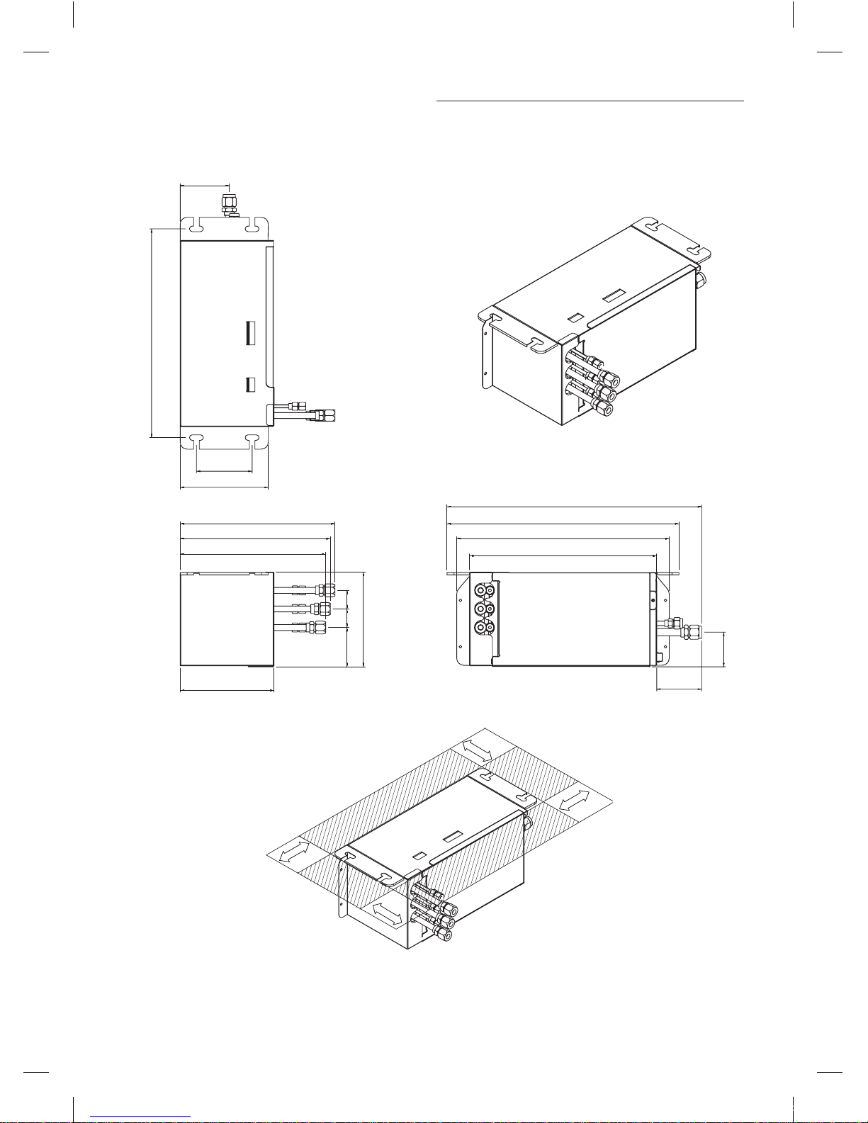
Preparation for Installation
Unit : mm(inch)
450(17.71)
105(4.13)
120(4.72)
100(3.93)
100(3.93)
50
(1.96)
380
(14.96)
190(7.48)
333(13.11)
Inspection area
549(21.61)
500(19.68)
458(18.03)
403(15.86)
97(3.81)
74(2.91)
85(3.34)
204(8.03)
40(1.57) 40(1.57)
323(12.71)
313(12.32)
Inspection area
NASA_Distributor Kit_IM_EN_03757A(1).indd 2 2013-01-18 오후 12:01:01
Page 2
3
ENGLISH
Electronic Expansion Valve Kit Installation
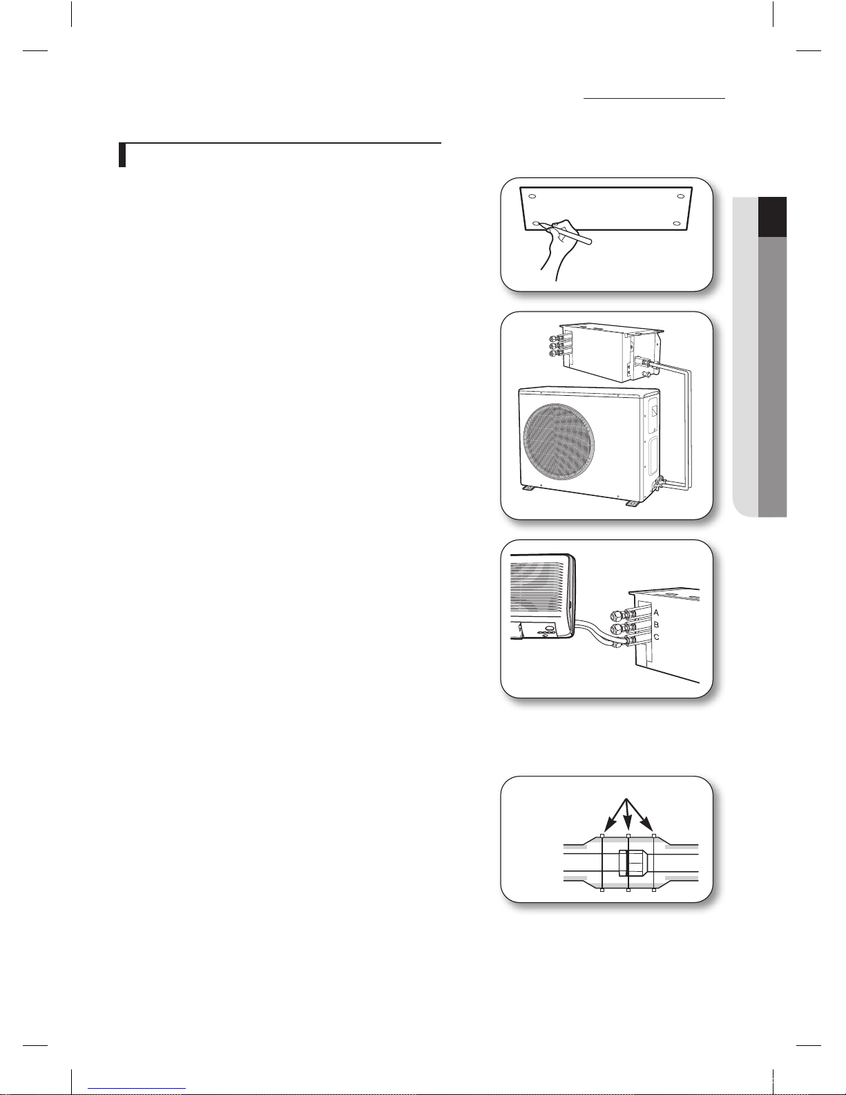
Connection of refrigerant piping & Installation
1. Decide an installation place that can support the electronic expansion
valve kit.
2. Connect the “IN” refrigerant pipe to the outdoor unit.
3. Connect the “OUT” refrigerant pipe to each indoor unit (A, B and C).
The liquid and gas pipes should not be crossed when piping
connection.
4. Insulate the connection piping. A joint part of pipe needs double
thickness of insulation.
5. The expansion valve has to be installed that the user has no access to
it.
Electronic
Expansion
valve
body
Nylon band
NASA_Distributor Kit_IM_EN_03757A(1).indd 3 2013-01-18 오후 12:01:02
Page 3
4
Electronic Expansion Valve Kit Installation (cont.)
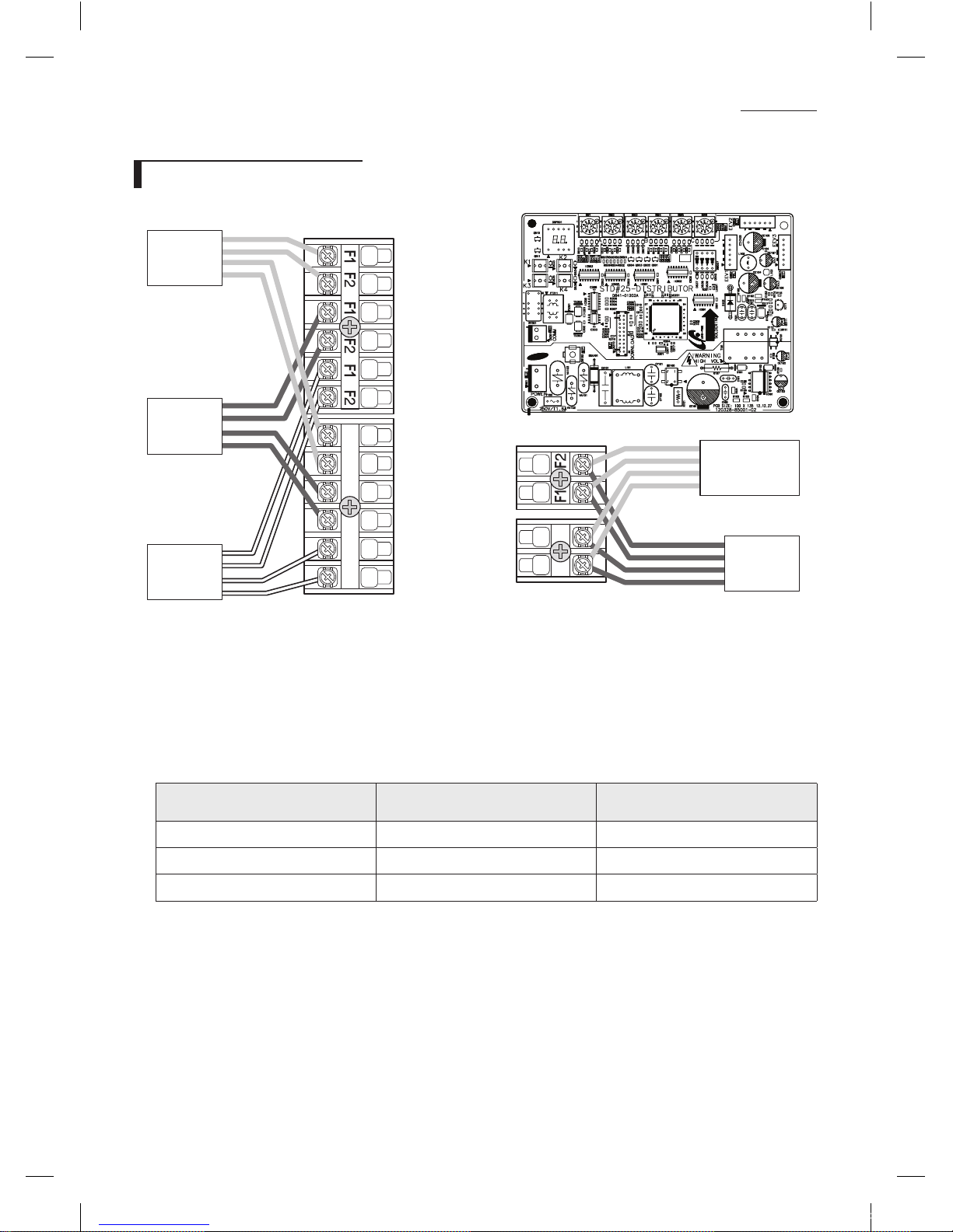
Wiring & Assigning address
1(L) 2(N)
1(L) 2(N) 1(L) 2(N) 1(L) 2(N)
Another
distributor kit
Outdoor
unit
Room A
Room B
Room C
1. Connect the AC power cable and communication cable from the outdoor unit to terminal, then connect the cable to
another electronic expansion valve kit.
2. Connect the AC power cable and communication cable to each indoor unit (A, B and C).
3. Align the SW01/SW02, SW03/SW04 and SW05/SW06’s addresses with A, B and C indoor units’.
Switch No.
Appropriate indoor unit
(Electronic expansion valve)
Connector No.
SW01/SW02 A EEV.1 CN801(YELLOW)
SW03/SW04 B EEV.2 CN802(BLUE)
SW05/SW06 C EEV.3 CN803(WHITE)
NASA_Distributor Kit_IM_EN_03757A(1).indd 4 2013-01-18 오후 12:01:03
Page 4
5
ENGLISH
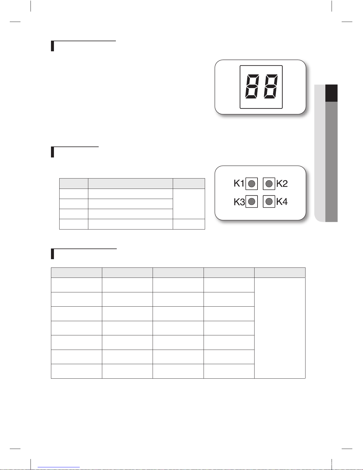
Function of Display
The numbers which is displayed on left are the status of indoor unit
checking status through communication with same outdoor unit. (If
it indicates 1, 3 and 7 that means the ADDRESS of indoor unit is set to
1, 3 and 7.)
The numbers which is displayed on right indicate the ADDRESS
of SW01/SW02, SW03/SW04 and SW05/SW06 in sequential. (If it
indicates 0, 1 and 2 that means the SW01/SW02 is set to 0, the SW03/
SW04 is set to 1, and the SW05/SW06 is set to 2.)
If the communication error occurs in distributor, the Er↔C0 message
will be shown on the display alternatively.
KEY function
If you press a KEY on the PCB, the display will show you a step of
appropriate electronic expansion valve.
KEY No. Meaning Example
K1 Step of electronic expansion valve A
19
(19 x 10 =
190 STEP)
K2 Step of electronic expansion valve B
K3 Step of electronic expansion valve C
K4 - -
Applicable capacity
Model A B C Refrigerant
MXD-E24K132✴
2 ~ 4.5 kW
(7000 ~ 15500 Btu/h)
5 ~ 9 kW
(17000 ~ 31000 Btu/h)
-
R-410A
MXD-E24K200✴
2 ~ 4.5 kW
(7000 ~ 15500 Btu/h)
2 ~ 4.5 kW
(7000 ~ 15500 Btu/h)
-
MXD-E24K232✴
2 ~ 4.5 kW
(7000 ~ 15500 Btu/h)
2 ~ 4.5 kW
(7000 ~ 15500 Btu/h)
5 ~ 9 kW
(17000 ~ 31000 Btu/h)
MXD-E24K300✴
2 ~ 4.5 kW
(7000 ~ 15500 Btu/h)
2 ~ 4.5 kW
(7000 ~ 15500 Btu/h)
2 ~ 4.5 kW
(7000 ~ 15500 Btu/h)
MXD-E32K200✴
5 ~ 9 kW
(17000 ~ 31000 Btu/h)
5 ~ 9 kW
(17000 ~ 31000 Btu/h)
-
MXD-E32K224✴
5 ~ 9 kW
(17000 ~ 31000 Btu/h)
5 ~ 9 kW
(17000 ~ 31000 Btu/h)
2 ~ 4.5 kW
(7000 ~ 15500 Btu/h)
MXD-E32K300✴
5 ~ 9 kW
(17000 ~ 31000 Btu/h)
5 ~ 9 kW
(17000 ~ 31000 Btu/h)
5 ~ 9 kW
(17000 ~ 31000 Btu/h)
NASA_Distributor Kit_IM_EN_03757A(1).indd 5 2013-01-18 오후 12:01:04
Page 5
NASA_Distributor Kit_IM_EN_03757A(1).indd 6 2013-01-18 오후 12:01:04
Page 6
Air Conditioner
installation manual
imagine the possibilities
Thank you for purchasing this Samsung product.
To receive more complete service, please
register your product at
www.samsung.com/register
This manual is made with 100% recycled paper.
Distributor Kit
MXD-E24K Series
MXD-E32K Series
EN IT ELES PT RU
FR DE AR
DB68-03757A(1)
NASA_Distributor Kit_IM_EN_03757A(1).indd 7 2013-01-18 오후 12:01:04
 Loading...