

Samsung MT3204 48A Installation Manual

MT3204 Series
Installation Manual
Describes product installation and requirement procedure.
Document Version 1.0
December 2018
Document Number: 2600-00NFJUGAA

This manual should be read and used as a guideline for properly installing and/or operating
the product. Owing to product variations across the range, any illustrations and photographs
used in this manual may not be a wholly accurate depiction of the actual products you are
using.
This manual may be changed for system improvement, standardization and other technical
reasons without prior notice.
© 2018 SAMSUNG Electronics Co., Ltd.
All Rights Reserved. The contents of this document/presentation contain proprietary information that
must be kept confidential. No part of this document shall be photocopied, reproduced, stored in a
retrieval system, or transmitted, in any form or by any means whether, electronic, mechanical, or
otherwise without the prior written permission of SAMSUNG Electronics Co., Ltd.
No warranty of accuracy is given concerning the contents of the information contained in this
publication. To the extent permitted by law no liability (including liability to any person by reason of
negligence) will be accepted by SAMSUNG Electronics Co., Ltd., its subsidiaries or employees for
any direct or indirect loss or damage caused by omissions from or inaccuracies in this document.
SAMSUNG Electronics Co., Ltd. reserves the right to change details in this publication without
notice.
SNMTC-v3-0312

Samsung Networks documentation is available at http://www.samsungdocs.com
MT3204 Series Installation Manual v1.0 iii
Copyright © 2018, All Rights Reserved.

Confidential
Contents
Preface ix
Conventions in this Document ........................................................................................................ ix
Revision History ................................................................................................................................ x
Organization of This Document ....................................................................................................... x
Related Documentation ................................................................................................................... x
Personal and Product Safety ........................................................................................................... xi
Equipment Markings ....................................................................................................................... xv
Chapter 1 Before Installation 1
MMU View and External Interface ................................................................................................... 1
MMU View ................................................................................................................................... 1
MMU External Interface .............................................................................................................. 2
Specifications ................................................................................................................................... 4
Cautions for Installation ................................................................................................................... 5
Before Installing ........................................................................................................................... 5
While Installing ............................................................................................................................ 5
After Installing ............................................................................................................................. 6
Installation Tools .............................................................................................................................. 7
Chapter 2 Installing System 10
Installation Procedure .................................................................................................................... 10
System Arrangement ..................................................................................................................... 11
Transporting and Unpacking .......................................................................................................... 14
Bringing in Items ........................................................................................................................ 14
Unpacking .................................................................................................................................. 14
MMU Handling ............................................................................................................................... 15
Fixing MMU .................................................................................................................................... 16
Fixing Unit Bracket ..................................................................................................................... 16
Fixing Pole Type ......................................................................................................................... 17
Fixing Wall Type ......................................................................................................................... 31
MMU Tilting & Swivelling .......................................................................................................... 40
Chapter 3 Connecting Cables 73
Cabling Procedure .......................................................................................................................... 73
Guidelines for Cable Connections .................................................................................................. 74
Cable Path Inspection ................................................................................................................ 74
Cable Cutting ............................................................................................................................. 75
Cable Installation ....................................................................................................................... 75
Cable Binding ............................................................................................................................. 76
Connector Attachment............................................................................................................... 76
Identification Tag Attachment ................................................................................................... 77
Cabling Diagram ............................................................................................................................. 78
Grounding ...................................................................................................................................... 79
Connecting Ground Cable .......................................................................................................... 79
Power Cabling ................................................................................................................................ 82
Connecting Power Cable ............................................................................................................ 83
Interface Cable Connection ............................................................................................................ 88
Remove/Insert Optical Module .................................................................................................. 88
MT3204 Series Installation Manual v1.0 iv
Copyright © 2018, All Rights Reserved.

Confidential
Contents
Connecting CPRI Cable ............................................................................................................... 90
Connecting UDA Cable ............................................................................................................... 94
Chapter 4 Inspect the Installation 99
Appendix A Acronyms 103
Appendix B Clean the Optical Connectors 104
Introduction ................................................................................................................................. 104
Measure the Optical Output and Connecting the Optical Connector ...................................... 104
Appendix C Standard Torque 106
MT3204 Series Installation Manual v1.0 v
Copyright © 2018, All Rights Reserved.

Confidential
List of Figures
Figure 1. MMU View ....................................................................................................................................... 2
Figure 2. MMU External Interface ................................................................................................................... 3
Figure 3. Procedure to Install the MMU ....................................................................................................... 10
Figure 4. MMU Arrangement_Pole Type Installation ................................................................................... 11
Figure 5. MMU Arrangement_Wall Type Installation ................................................................................... 12
Figure 6. MMU Arrangement_Swivelling ...................................................................................................... 13
Figure 7. Transporting the MMU .................................................................................................................. 15
Figure 8. Fixing Unit Bracket (1) .................................................................................................................... 16
Figure 9. Fixing Unit Bracket (2) .................................................................................................................... 17
Figure 10. Fixing Pole Mount Bracket-Bottom (1)........................................................................................... 18
Figure 11. Fixing Pole Mount Bracket-Bottom (2)........................................................................................... 19
Figure 12. Fixing Pole Mount Bracket-Bottom (3)........................................................................................... 20
Figure 13. Fixing Pole Mount Bracket-Top (1) ................................................................................................. 21
Figure 14. Fixing Pole Mount Bracket-Top (2) ................................................................................................. 22
Figure 15. Fixing Pole Mount Bracket-Top (3) ................................................................................................. 22
Figure 16. Lifting MMU & Pole Mount Bracket Assembly-Top (1) .................................................................. 23
Figure 17. Lifting MMU & Pole Mount Bracket Assembly-Top (2) .................................................................. 23
Figure 18. Lifting MMU & Pole Mount Bracket Assembly-Top (3) .................................................................. 24
Figure 19. Fixing Pole Mount Bracket Assembly-Top (1) ................................................................................ 25
Figure 20. Fixing Pole Mount Bracket Assembly-Top (2) ................................................................................ 25
Figure 21. Fixing Pole Mount Bracket Assembly-Top (3) ................................................................................ 26
Figure 22. Fixing Pole Mount Bracket Assembly-Top (4) ................................................................................ 26
Figure 23. Fixing Pole Mount Bracket Assembly-Top (5) ................................................................................ 27
Figure 24. Fixing Pole Mount Bracket Assembly-Top (6) ................................................................................ 27
Figure 25. Fixing MMU on the Pole (1) ........................................................................................................... 29
Figure 26. Fixing MMU on the Pole (2) ........................................................................................................... 30
Figure 27. Fixing MMU on the Pole (3) ........................................................................................................... 31
Figure 28. MMU Marking Dimensions ............................................................................................................ 33
Figure 29. Marking_Wall Mount Bracket-Top Assembly ................................................................................ 34
Figure 30. Drilling & Anchor (1) ....................................................................................................................... 35
Figure 31. Drilling & Anchor (2) ....................................................................................................................... 36
Figure 32. Fixing Wall Mount Bracket-Top Assembly (1) ................................................................................ 37
Figure 33. Fixing Wall Mount Bracket-Top Assembly (2) ................................................................................ 37
Figure 34. Assembling Wall Mount Bracket-Bottom....................................................................................... 38
Figure 35. Fixing MMU .................................................................................................................................... 39
Figure 36. MMU Down Tilting (1) .................................................................................................................... 42
Figure 37. MMU Down Tilting (2) .................................................................................................................... 43
Figure 38. MMU Down Tilting (3) .................................................................................................................... 44
Figure 39. MMU Down Tilting (4) .................................................................................................................... 45
Figure 40. MMU Down Tilting (5) .................................................................................................................... 45
Figure 41. MMU Down Tilting (6) .................................................................................................................... 46
Figure 42. Bracket Change for MMU Up Tilting (1) ......................................................................................... 48
Figure 43. Bracket Change for MMU Up Tilting (2) ......................................................................................... 49
Figure 44. Bracket Change for MMU Up Tilting (3) ......................................................................................... 50
Figure 45. Bracket Change for MMU Up Tilting (4) ......................................................................................... 52
Figure 46. Bracket Change for MMU Up Tilting (5) ......................................................................................... 53
Figure 47. Lifting MMU & Pole Mount Bracket Assembly-Top (1) .................................................................. 54
MT3204 Series Installation Manual v1.0 vi
Copyright © 2018, All Rights Reserved.

Confidential
List of Figures
Figure 48. Lifting MMU & Pole Mount Bracket Assembly-Top (2) .................................................................. 54
Figure 49. Lifting MMU & Pole Mount Bracket Assembly-Top (3) .................................................................. 55
Figure 50. Fixing Pole Mount Bracket Assembly-Top (Up-Tilting) (1) ............................................................. 56
Figure 51. Fixing Pole Mount Bracket Assembly-Top (Up-Tilting) (2) ............................................................. 56
Figure 52. Fixing Pole Mount Bracket Assembly-Top (Up-Tilting) (3) ............................................................. 57
Figure 53. Fixing Pole Mount Bracket Assembly-Top (Up-Tilting) (4) ............................................................. 57
Figure 54. Fixing Pole Mount Bracket Assembly-Top (Up-Tilting) (5) ............................................................. 58
Figure 55. Fixing Pole Mount Bracket Assembly-Top (Up-Tilting) (6) ............................................................. 58
Figure 56. Fixing Pole Mount Bracket Assembly-Top (Up-Tilting) (7) ............................................................. 59
Figure 57. Fixing MMU (Up-Tilting) on the Pole (1) ........................................................................................ 60
Figure 58. Fixing MMU (Up-Tilting) on the Pole (2) ........................................................................................ 61
Figure 59. Fixing MMU on the Pole (3) ........................................................................................................... 62
Figure 60. MMU Up Tilting (1) ........................................................................................................................ 64
Figure 61. MMU Up Tilting (2) ........................................................................................................................ 65
Figure 62. MMU Up Tilting (3) ........................................................................................................................ 66
Figure 63. MMU Up Tilting (4) ........................................................................................................................ 67
Figure 64. MMU Up Tilting (5) ........................................................................................................................ 67
Figure 65. MMU Up Tilting (6) ........................................................................................................................ 68
Figure 66. MMU Swiveling Adjustment (1) ..................................................................................................... 70
Figure 67. MMU Swiveling Adjustment (2) ..................................................................................................... 71
Figure 68. MMU Swiveling Adjustment (3) ..................................................................................................... 72
Figure 69. Procedure to Connect System Cable .............................................................................................. 73
Figure 70. Cable Connection Procedure.......................................................................................................... 74
Figure 71. Cable Diagram ................................................................................................................................ 78
Figure 72. Connecting Ground Cable (1) ......................................................................................................... 80
Figure 73. Connecting Ground Cable (2) ......................................................................................................... 81
Figure 74. Power Equipment Elements ........................................................................................................... 82
Figure 75. Connecting Power Cable (1) ........................................................................................................... 84
Figure 76. Connecting Power Cable (2) ........................................................................................................... 85
Figure 77. Connecting Power Cable (3) ........................................................................................................... 86
Figure 78. Optical Module Removal (1) .......................................................................................................... 88
Figure 79. Optical Module Removal (2) .......................................................................................................... 88
Figure 80. Optical Module Removal (3) .......................................................................................................... 89
Figure 81. Optical Module Insert .................................................................................................................... 89
Figure 82. Connecting CPRI Cable (1) .............................................................................................................. 91
Figure 83. Connecting CPRI Cable (2) .............................................................................................................. 91
Figure 84. Connecting CPRI Cable (3) .............................................................................................................. 92
Figure 85. Connecting CPRI Cable (4) .............................................................................................................. 93
Figure 86. Connecting CPRI Cable (5) .............................................................................................................. 93
Figure 87. Connecting UDA Cable (1) .............................................................................................................. 95
Figure 88. Connecting UDA Cable (2) .............................................................................................................. 96
Figure 89. Connecting UDA Cable (3) .............................................................................................................. 96
Figure 90. Connecting UDA Cable (4) .............................................................................................................. 97
Figure 91. Installation Inspection Procedure .................................................................................................. 99
MT3204 Series Installation Manual v1.0 vii
Copyright © 2018, All Rights Reserved.

Confidential
List of Tables
Table 1. Specifications ................................................................................................................................... 4
Table 1. Basic Installation Tools ..................................................................................................................... 7
Table 2. Parts and Tools for Fixing Unit Bracket on MMU ........................................................................... 16
Table 3. Parts and Tools for Assembling Pole Mount Bracket-Bottom ........................................................ 18
Table 4. Parts and Tools for Fixing Pole Mount Bracket-Top ....................................................................... 20
Table 5. Parts and Tools for Fixing Pole Mount Bracket Assembly-Top....................................................... 24
Table 6. Parts and Tools for Fixing MMU on the Pole.................................................................................. 28
Table 7. Tools for Marking ........................................................................................................................... 32
Table 8. Parts and Tools for Drilling & Anchoring ........................................................................................ 34
Table 9. Anchor Bolt Drill Bits and Hole Depth ............................................................................................ 34
Table 10. Parts and Tools for Fixing Mount Bracket-Top Assembly .............................................................. 36
Table 11. Parts and Tools for Assembling Wall Mount Bracket-Bottom ....................................................... 37
Table 12. Parts and Tools for Fixing MMU ..................................................................................................... 38
Table 13. MMU Down Tilting Adjustment Tools ............................................................................................ 40
Table 14. Parts and Tools for MMU Up Tilting ............................................................................................... 46
Table 15. Parts and Tools for Fixing Pole Mount Bracket Assembly-Top (Up-Tilting) ................................... 55
Table 16. Parts and Tools for Fixing MMU on the Pole.................................................................................. 59
Table 17. MMU Up Tilting Adjustment Tools................................................................................................. 62
Table 18. Tools for Swiveling MMU ............................................................................................................... 69
Table 19. Recommended Minimum Allowed Cable bend Radius .................................................................. 76
Table 20. MMU Connection Cable ................................................................................................................. 78
Table 21. Parts and Tools for Connecting Ground Cable ............................................................................... 79
Table 22. Parts and Tools for Connecting Power Cable ................................................................................. 83
Table 23. DC Power Cable/Connector Pin Map ............................................................................................. 83
Table 24. Parts and Tools for connecting CPRI Cable .................................................................................... 90
Table 25. Parts and Tools for Connecting UDA Cable .................................................................................... 94
Table 26. UDA Cable Pin Map ........................................................................................................................ 95
Table 27. Construction Situation Checklist .................................................................................................. 100
Table 28. Standard Torque Value for Fastening Bolts ................................................................................. 106
Table 29. Brass Bolts Torque Value.............................................................................................................. 106
Table 30. Connector Connection Torque Value ........................................................................................... 106
MT3204 Series Installation Manual v1.0 viii
Copyright © 2018, All Rights Reserved.

Preface
Symbol
Description
Indicates a task.
Indicates a shortcut or an alternative method.
Provides additional information.
Provides information or instructions that you should follow to avoid service
failure or damage to equipment.
Provides information or instructions that you should follow to avoid personal
injury or fatality.
Provides antistatic precautions that you should observe.
This manual describes how to install the 3.5 GHz CBRS MMU, MT3204-48A,
including how to connect cables.
Conventions in this Document
Samsung Networks product documentation uses the following conventions.
Symbols
Confidential
Menu Commands
menu | command
This indicates that you must select a command on a menu, where menu is the
name of the menu, and command is the name of the command on that menu.
File Names and Paths
These are indicated by a bold typeface. For example:
Copy filename.ext into the /home/folder1/folder2/bin/ folder.
User Input and Console Screen Output Text
The input and output text is presented in the Courier New font. For example,
context <designated epc-context-name>
The CLI command is presented in capital letters and Courier New, bold style.
For example, Type the RTRV-NE-STS command in the input field.
The YANG object is presented in the small letters and boldface. For example,
eutran-cell-conf-idle
MT3204 Series Installation Manual v1.0 ix
Copyright © 2018, All Rights Reserved.

Preface
Document Version
Publication Date
Remarks
1.0
December 2018
First version
Section
Title
Description
Chapter 1
Before Installation
This chapter introduces MMU and describes the items that
should be understood before installation.
Chapter 2
Installing System
This chapter describes the procedures to install the MMU.
Chapter 3
Connecting Cables
This chapter describes the procedures to connect the cables to
the installed MMU.
Chapter 4
Inspect the Installation
This chapter describes the procedures of inspecting installation
status after the MMU installation and cabling is completed.
Appendix A
Acronyms
This appendix describes the acronyms used in this manual.
Appendix B
Clean the Optical
Connectors
This appendix describes the procedure of cleaning the optical
connector and cleaning tool.
Appendix C
Standard Torque
This appendix describes the standard torque when fastening
the bolt.
Revision History
The following table lists all versions of this document.
Organization of This Document
Confidential
Related Documentation
LTE eNB System Description
MT3204 Series Installation Manual v1.0 x
Copyright © 2018, All Rights Reserved.

Preface
Personal and Product Safety
This product safety information includes European directives, which you must
follow. If these do not apply in your country, please follow similar directives that
do apply in your country.
Electrical
The product is designed to operate from a -48 V DC supply and is therefore
classified as Safe Extra Low Voltage (SELV) equipment.
All structural parts are grounded and all input and outputs have built-in isolation
from the network. All input and output ports that connect to external power
sources are designed to meet relevant national safety requirements.
The product contains hazardous energy levels as defined by EN 60950. Care must
be taken when maintaining this equipment as injury to personnel or damage to the
equipment could result from mistakes. Maintenance should only be carried out by
trained and competent engineers who are familiar with the relevant procedures and
instructions.
Confidential
Lasers
The product is fitted with optic modules rated as Class 1 radiation-emitting devices
under EN 60825-1. During installation, operation, and maintenance, never look
into the end of an optical fiber directly or by reflection either with the naked eye or
through an optical instrument. Do not operate equipment with exposed fiber
connectors-cover these with fiber cables or blanking caps. Do not remove
equipment covers during operation unless requested to do so in the documentation.
Carry out normal safety precautions when trimming fibers during installation.
Manual Handling
Care should be taken when handling equipment. Give due consideration to the
weight of the equipment, the physical capability of the individual(s) handling the
equipment, and movements such as twisting, bending and stooping, which could
lead to skeletal and muscular injuries.
Installation
Installation must be carried out by trained and competent engineers only. All
relevant safety measures should be taken to ensure equipment is not connected to
live power and transmission sources during installation. Equipment must be
correctly installed in order to meet the relevant safety standards and approval
conditions.
Each power feed to the unit requires a separate fused feed from the provided
power supply. The cable between the power distribution point and the installed
equipment must have a minimum cross-sectional area of 2.5 mm2.
MT3204 Series Installation Manual v1.0 xi
Copyright © 2018, All Rights Reserved.

Rack-mountable equipment must be placed in a standard 19-inch rack and secured
with the appropriate fixings as detailed in the installation manual.
Maintenance
Maintenance must only be carried out by a suitably trained and competent
technician. All safety instructions must be carefully observed at all times.
Equipment covers should not be removed while live power and transmission is
connected unless in a controlled environment by trained technicians.
Fire
The product is powered from a -48 V DC supply. To protect against fire, the
equipment is fused.
Environment
The product must be operated in an environment with the specified relative
humidity and ambient temperature ranges.
Confidential
Preface
Keep all liquids away from the equipment as accidental spillage can cause severe
damage.
Cooling
The product cools down by its own set of cooling fans housed in a fan module.
Each fan module detects a fan that is not operating normally. LEDs on the front
panel of the fan tray provide an alarm indication in the event of fan failure.
In the event of fan failure, take urgent remedial action to restore full cooling
capacity.
Take appropriate measures to ensure that fan modules do not start spinning during
repair and maintenance procedures.
Anti-Static Precautions
The circuit boards and other modules in the product are sensitive to and easily
damaged by static electricity. If any card or sub-assembly is removed from the
unit, the following anti-static precautions must be observed at all times:
Service personnel must wear anti-static wrist straps.
Circuit boards and sub-assemblies must be placed on ground conductive mats
or in conductive bags.
All tools must be discharged to ground before use.
The anti-static wrist strap and cord must be checked at regular intervals for
their suitability for use.
MT3204 Series Installation Manual v1.0 xii
Copyright © 2018, All Rights Reserved.

Preface
Grounding
To comply with EN 60950, the equipment must be connected to a safety
grounding point via a permanent link. Grounding points are located on the product
for this purpose. Always connect the ground cable before fitting other cables. The
product must remain grounded continuously unless all connections to the power
supply and data network are all removed.
If equipment is grounded through a cabinet or rack, make sure it is done so
properly according to the installation instructions.
Power Supply Connection
The equipment is designed to be powered from a -48 V DC supply. Power
connections and installation of associated wiring must be carried out by a suitably
qualified technician.
Only devices that comply with all relevant national safety requirements should be
connected to the unit's power supply inlets. Other usage will invalidate any
approval given to this equipment.
Confidential
Connection of this equipment to devices that are not marked with all relevant
national safety requirements may produce hazardous conditions on the network.
When the power supply is obtained by a rectifier/safety isolation transformer, the
supply must meet the requirements of EN 60950 providing double/reinforced
insulation between hazardous voltages and SELV/TNV circuits. Any battery must
be separated from hazardous voltages by reinforced insulation.
Indirect Connection
Before indirectly connecting any equipment to another device through a shared
power supply, ALWAYS seek advice from a competent engineer.
Devices that are not marked according to the relevant national safety standards
may produce hazardous conditions on the network.
Product Disposal
To reduce the environmental impact of products, Samsung has joined WEEE
compliance activities.
The WEEE symbol on the product indicates that the product is covered by the
European Directive 2002/96/CE for the disposal of Waste Electrical and Electronic
Equipment (WEEE). This means that the product should be disposed of separately
from the municipal waste stream via designated collection facilities appointed by
the government or the local authorities. This will help prevent potential negative
consequences for the environment and human health. Please check the terms and
conditions of the purchase contract for information about correct disposal.
MT3204 Series Installation Manual v1.0 xiii
Copyright © 2018, All Rights Reserved.

Preface
Battery Disposal
The product contains a battery on the processor card. The battery should not be
disposed of with other household waste. Where marked, the chemical symbols Hg,
Cd or Pb indicate that the battery contains mercury, cadmium or lead above the
reference levels in EC Directive 2006/66. The battery incorporated in this product
is not user replaceable. For information on its replacement, please contact your
service provider. Do not attempt to remove the battery or dispose it in a fire. Do
not disassemble, crush, or puncture the battery.
End of life recycling materials information is available from Samsung.
California USA Only
This Perchlorate warning applies only to primary CR (Manganese Dioxide)
Lithium coin cells in the product sold or distributed ONLY in California USA
‘Perchlorate Material-special handling may apply, See
www.dtsc.ca.gov/hazardouswaste/perchlorate.’
Confidential
Compliance Statements for the USA
Any changes or modifications that art not expressly approved by the manufacturer
for compliance could void the user's authority to operate the equipment.
MT3204 Series Installation Manual v1.0 xiv
Copyright © 2018, All Rights Reserved.

Preface
This marking on the product, accessories or literature indicates that the
product and its electronic accessories (e.g. charger, headset, USB cable)
should not be disposed of with other household waste at the end of their
working life. To prevent possible harm to the environment or human
health from uncontrolled waste disposal, please separate these items
from other types of waste and recycle them responsibly to promote the
sustainable reuse of material resources.
Household users should contact either the retailer where they purchased
this product, or their local government office, for details of where and how
they can take these items for environmentally safe recycling.
Business users should contact their supplier and check the terms and
conditions of the purchase contract. This product and its electronic
accessories should not be mixed with other commercial wastes for
disposal.
Correct disposal of batteries in this product
(Applicable in countries with separate collection systems.)
The marking on the battery, manual or packaging indicates that the
battery in this product should not be disposed of with other household
waste. Where marked, the chemical symbols Hg, Cd or Pb indicate that
the battery contains mercury, cadmium or lead above the reference levels
in EC Directive 2006/66.
The battery incorporated in this product is not user replaceable. For
information on its replacement, please contact your service provider. Do
not attempt to remove the battery or dispose it in a fire. Do not
disassemble, crush, or puncture the battery. If you intend to discard the
product, the waste collection site will take the appropriate measures for
the recycling and treatment of the product, including the battery.
Hot surface warning
Allow to cool before servicing.
Do not touch before cooling.
Notice! Be careful not to touch due to high temperature.
The system must be installed in a restricted area, and make sure the
work is done by personnel properly trained for the job.
Protective earth
MMU should be grounded.
Equipment Markings
Confidential
MT3204 Series Installation Manual v1.0 xv
Copyright © 2018, All Rights Reserved.

Chapter 1 Before
Installation
This chapter introduces the MMU system and describes the items that you should
know before installation.
MMU View and External Interface
This section provides the physical structure of the MMU and its interfaces.
MMU View
The figure below depicts the physical structure of the MMU.
Confidential
MT3204 Series Installation Manual v1.0 1
Copyright © 2018, All Rights Reserved.
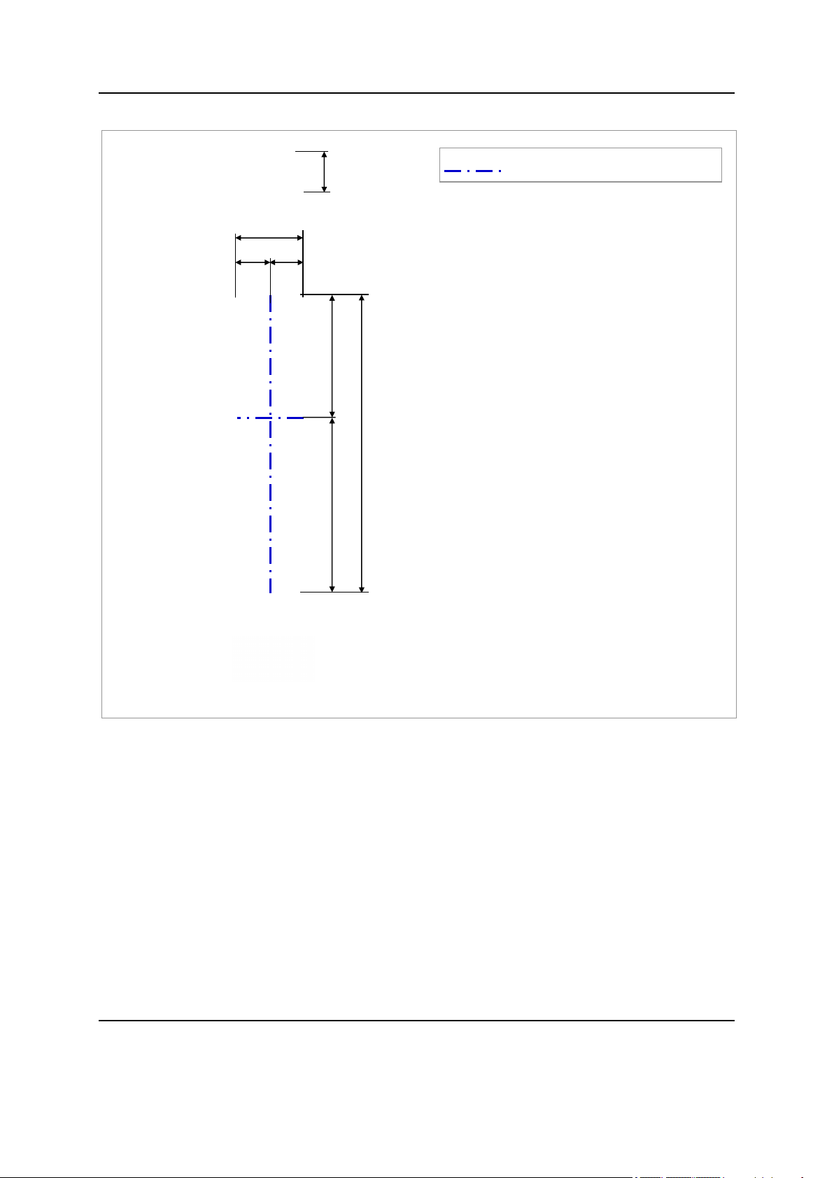
Figure 1. MMU View
[Bottom View]
[Front View]
5.27
(134)
[Right View]
[Left View]
[Rear View]
[Top View]
9.0 (230)
40.3 (1023)
15.6 (396.5)
4.5
(115)
4.5
(115)
24.7 (626.5)
Unit: in. (mm)
: Center Line for the Antenna Element
Confidential
Chapter 1 Before Installation
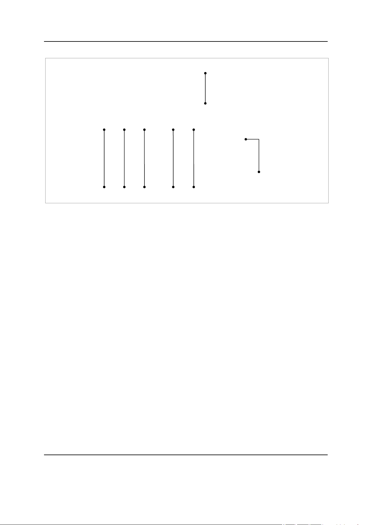
MMU External Interface
The figure below depicts the external interface structure of the MMU.
MT3204 Series Installation Manual v1.0 2
Copyright © 2018, All Rights Reserved.
Chapter 1 Before Installation
DC_PWR
L0
Ground Terminal
[MMU Bottom View]
L1
L2
L3
UDA
Figure 2. MMU External Interface
Confidential
MT3204 Series Installation Manual v1.0 3
Copyright © 2018, All Rights Reserved.

Chapter 1 Before Installation
Item
MT3204-48A
Air technology
LTE
Operating Frequency (MHz)
3,550 to 3,700
RF Chain
32T32R
Antenna Element
96 (4V8H)
IBW/OBW
150 MHz/40 MHz
Channel Bandwidth/Capacity
20 MHz × 2 Carrier
RF Output Power/EIRP
6.3 W (47 dBm per 10 MHz EIRP)
Modulation (DL/UL)
Up to 256 QAM/64 QAM
MIMO Layer
DL: 8L, UL: 2L
Fronthaul
CPRI (10 Gbps × 4 port, Duplex)
Input Voltage
-48 V DC (-38 to -57 V DC)
Power Consumption
428 W (100% Load, U/D 2-7)
Dimension (W × D × H)
9.0 in.(230 mm) × 5.3 in.(134 mm) × 40.3 in.(1023 mm)
Weight
< 53.57 lb (24.3 kg, with port guard)
Operating Temperature
-40 to +50°C (without Solar load)
Operating Humidity
5 to 100[%](RH), condensing, not to exceed 30 g/m3
absolute humidity
Cooling Method
Natural convection cooling
Function Split
LTE:DL-Option 7-2a, UL-Option 8
Spectrum Analyzer
TX, RX
Altitude
-60~1,800 m
Earthquake
Telcordia GR-63-CORE Section 4.4.1
(Earthquake Risk Zone4)
Vibration in Use
Transportation Vibration
Telcordia GR-63-CORE Section 4.4.4
Telcordia GR-63-CORE Section 4.4.5
IP rating
IP65
EMC
FCC part 15
RF
FCC CFR 47 Part 96
Beam Steering Range
Horizontal
TBD
Vertical
TBD
Safety
UL 60950-1
Installation
Pole/Wall mounting
Specifications
The table below outlines the main specifications of the MMU.
Table 1. Specifications
Confidential
MT3204 Series Installation Manual v1.0 4
Copyright © 2018, All Rights Reserved.

Chapter 1 Before Installation
Cautions for Installation
Observe the safety instructions described in this section when installing the
system.
Installation should be done in accordance with the applicable local electric codes.
Before Installing
Before starting the installation, ensure the following:
Post warning signs in areas where high-voltage cables are installed.
Post ‘off limit’ signs in areas where accidents are most expected.
Use guardrails or fences to block open areas such as ditches, open roof areas,
and scaffolds.
Install the system in the restricted access area.
Confidential
While Installing
During installation, ensure the following:
The system power must be cut off before installing.
Ensure that the power switch of the power supply is off when installing the system.
Installing the system with power on may cause system damage or fatal human
injury when connecting or disconnecting cables.
Ensure that workers wear protection gloves and goggles to prevent injury from
debris while drilling holes in a wall or ceiling.
Do not wear accessories such as watches and rings to prevent electrical shock.
Cover unused ports with a cap. This prevents foreign substances from entering into
the unused ports.
To prevent foreign substances, outdoor air, and moisture from entering the cable
inlet (including cable gland and conduit), finish the inlet as follows:
- Unused inlet: Use the hole finishing materials including cap and rubber packing.
- Cable-installed inlet: After cable installation, block any space in the inlet with
tape, compressed sponge, rubber packing, and silicone.
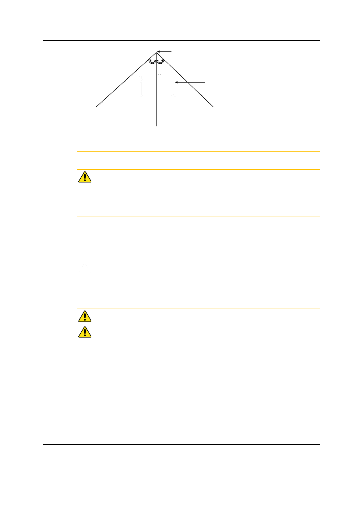
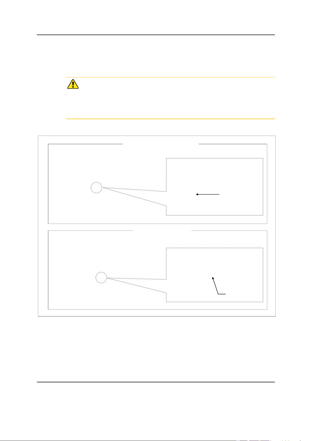
When operator installs the MMU, the MMU must be within the protective angle
(left/right side 45° each from the central axis) to prevent the MMU from lightning
damage.
MT3204 Series Installation Manual v1.0 5
Copyright © 2018, All Rights Reserved.
Confidential
Lightning Rod
45°
45°
MMU
Chapter 1 Before Installation
Keep a safe distance (1.3m) between the base station antenna and people.
Do not co-locate nor operate in conjunction with any other antenna or transmitter
for the protection of general public from exposure to radio frequency
electromagnetic field
After Installing
After installation, remove any debris produced during the work and clean up the
installation site.
In the system, the laser beam light runs through the optical cable. The workers
must handle the optical cables with care as the laser beam can seriously damage
the eyes.
Ensure that the workers do not damage installed cables while cleaning the system.
While cleaning the power supply device, take precaution that the device does not
come in contact with foreign objects that may cause power failure.
MT3204 Series Installation Manual v1.0 6
Copyright © 2018, All Rights Reserved.

Chapter 1 Before Installation
No.
Name
Specification
Purpose of use
1
Torque Driver
Apply a torque range: 20 to 90
lbf·in
Fastening M6 SEMS
2
Screw Driver Bit
'+', No. 3
Fastening M6 SEMS
3
Screw Driver
'+', No. 3
Fastening M6 SEMS
4
Torque Wrench
Apply a torque range: 10 to 50
lbf·in
Tightening M6 hexagonal. bolt
Apply a torque range: 100 to 400
lbf·in
Tightening M10, M12 hexagonal.
bolt
5
Torque Wrench Spanner
Head
Apply hexagonal bolt head: 10
mm (for 10 to 50 lbf·in)
Tightening M6 hexagonal bolt
Apply hexagonal bolt head: 17
mm (for 100 to 400 lbf·in)
Tightening M10 hexagonal nut
Apply hexagonal bolt head: 19
mm (for 100 to 400 lbf·in)
Tightening M12 hexagonal nut
6
Spanner
10 mm
Tightening M6 hexagonal. bolt
17 mm
Tightening M10 hexagonal. bolt
19 mm
Tightening M12 hexagonal. bolt
7
Tape Measure
16 ft./150 ft.
Measuring length
8
Level
Normal
Levelling horizontality and verticality
9
Power Extension Cable
100 ft.
Basic tool
10
Hammer Drill
Normal
Wall Type Drilling
Installation Tools
The basic tools required for installation are listed in the table below. The
additional tools required for each site need to be identified and arranged during a
site survey before starting the installation.
Table 1. Basic Installation Tools
Confidential
MT3204 Series Installation Manual v1.0 7
Copyright © 2018, All Rights Reserved.

Confidential
No.
Name
Specification
Purpose of use
11
Optical Connector Cleaner
For LC Connector
Cleaning Optical Connector
12
Concrete Drill Bit
17 mm
Setting M12 Anchor
13
Anchor Punch
M12
Setting M12 anchor
14
Hammer
Normal
Fixing anchor
15
Vacuum Cleaner
Normal
Removing dust during the drilling
work
16
Cable Cutter
0.2-1.3 in. (6-32 mm)
Cutting cable
17
Crimping Tool
14 AWG-4 AWG (1.5 to 16 mm2)
Crimping pressure terminal
18
Cable Stripper
Apply cable thickness: 1.5 to 6.2
in. (4 to 16 mm)
Removing cable sheath
19
Nipper
Basic Tool
Cutting cable
20
Flush cutter
Basic Tool
For cutting cable tie
21
Industrial Scissor
Basic Tool
Cutting
22
Knife
Basic Tool
Cutting
23
Heating Gun
50°C to 300°C
Shrinking the feeder cable tube
24
Multi tester
Digital Pocket Tester
Checking voltage and current to
Chapter 1 Before Installation
MT3204 Series Installation Manual v1.0 8
Copyright © 2018, All Rights Reserved.

Confidential
No.
Name
Specification
Purpose of use
detect cable disconnection
25
Angle Meter
Normal
Checking MMU Tilting
26
Fiber Optical Test Set
Wave length:
1270 nm, 1310 nm, 1550 nm
(single mode)
850 nm, 1310 nm (multi-mode)
Checking optical level
27
Antenna Alignment Tool
-
Checking azimuth and tilting
Chapter 1 Before Installation
The required installation tools may vary depending on the site conditions.
In addition to the basic tools, protractor, ladder, safety equipment, and cleaning
tools must also be arranged, considering the site conditions.
MT3204 Series Installation Manual v1.0 9
Copyright © 2018, All Rights Reserved.
Chapter 2 Installing System
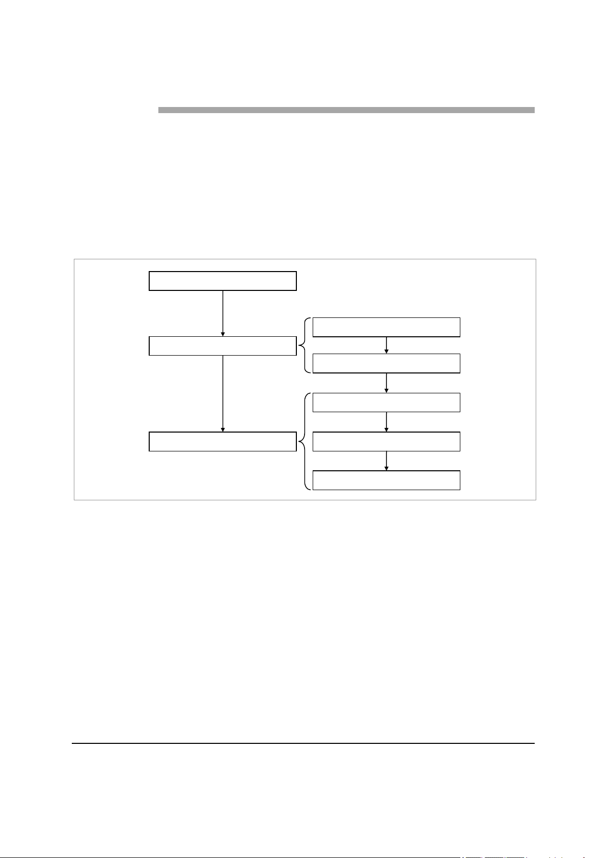
Foundation Work
Unpacking and Transporting
Fixing System
Unpacking Items
Bringing in Items
Fixing Unit Bracket
Fixing Mounting Bracket
Fixing MMU
This chapter describes the procedures for transporting, unpacking, and installing
the MMU.
Installation Procedure
The figure below depicts the overall procedures for installing the MMU.
Figure 3. Procedure to Install the MMU
Confidential
MT3204 Series Installation Manual v1.0 10
Copyright © 2018, All Rights Reserved.
Chapter 2 Installing System
Unit: in. (mm)
[Down Tilting 15o]
[Tilting 0o]
[Top View]
20.1 (510)
[Top View]
28.3 (720)
≥ 31 (800)
≥ 12 (300)
[Front View]
≥ 12 (300)
≥ 16 (400)
≥ 31 (800)
Example Pole size
(Ф 4.5 in./114.3 mm)
Pole Size (Diameter)
Length of Stud Bolt
50 A, 65 A, 80 A, 90 A, 100 A
8.7 in. (220 mm)
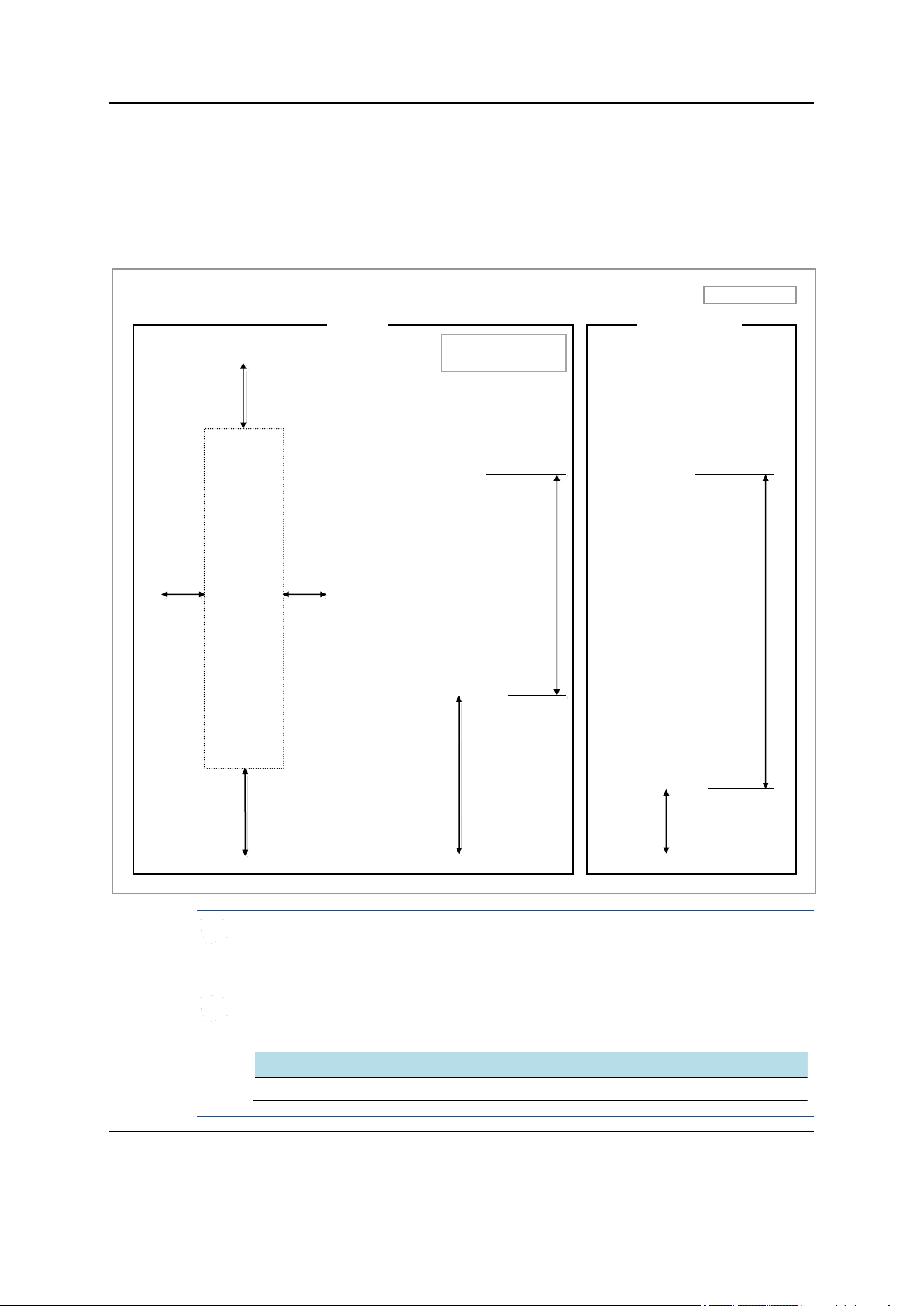
System Arrangement
A minimum distance must be secured around the MMU, in each direction for
installation and maintenance.
Figure 4. MMU Arrangement_Pole Type Installation
Confidential
MT3204 Series Installation Manual v1.0 11
Copyright © 2018, All Rights Reserved.
The dimensions of the front of the MMU change according to the tilt angle, and
the maximum dimensions are described in the figure below (MMU Arrangement_
Down Tilting 15°).
When fixing a mounting bracket, the length of stud bolts are 8.7 in. (220 mm) for
the pole diameter 50~100 A.
Chapter 2 Installing System
Unit: in. (mm)
[Down Tilting 15o]
[Tilting 0o]
[Front View]
[Top View]
≥ 16 (400)
≥ 12 (300)
18.6 (476)
W: 230
H: 1023
[Top View]
26.8 (686)
Wall
Wall
≥ 31 (800)
≥ 12 (300)
≥ 31 (800)
≥ 31 (800)
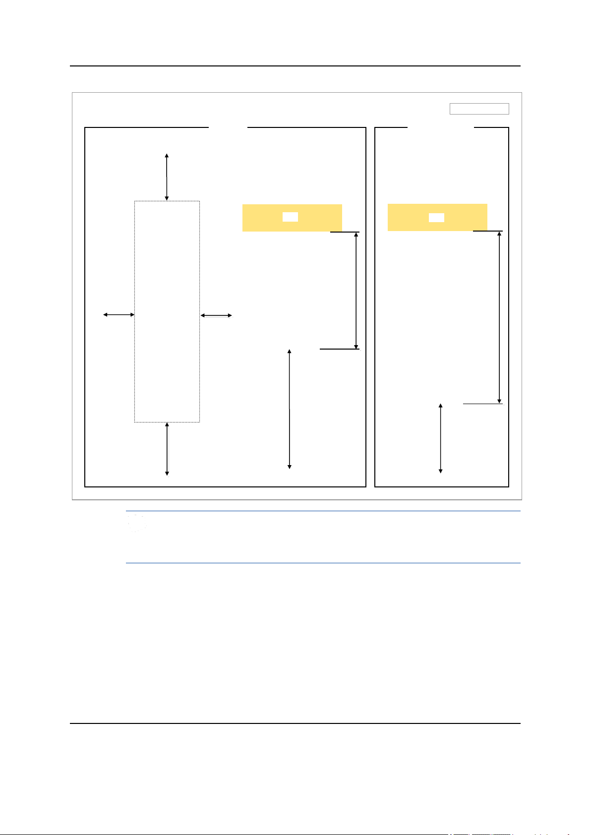
Figure 5. MMU Arrangement_Wall Type Installation
Confidential
The dimensions of the front of the MMU change according to the tilt angle, and
the maximum dimensions are described in the figure below (MMU Arrangement_
Down Tilting 15°).
MT3204 Series Installation Manual v1.0 12
Copyright © 2018, All Rights Reserved.
Chapter 2 Installing System
Unit: in. (mm)
[Left Swivelling 30o]
[Right Swivelling 30o]
[Top View]
18.8 (479)
[Top View]
17.6 (448)
17.6 (448)
18.8 (479)
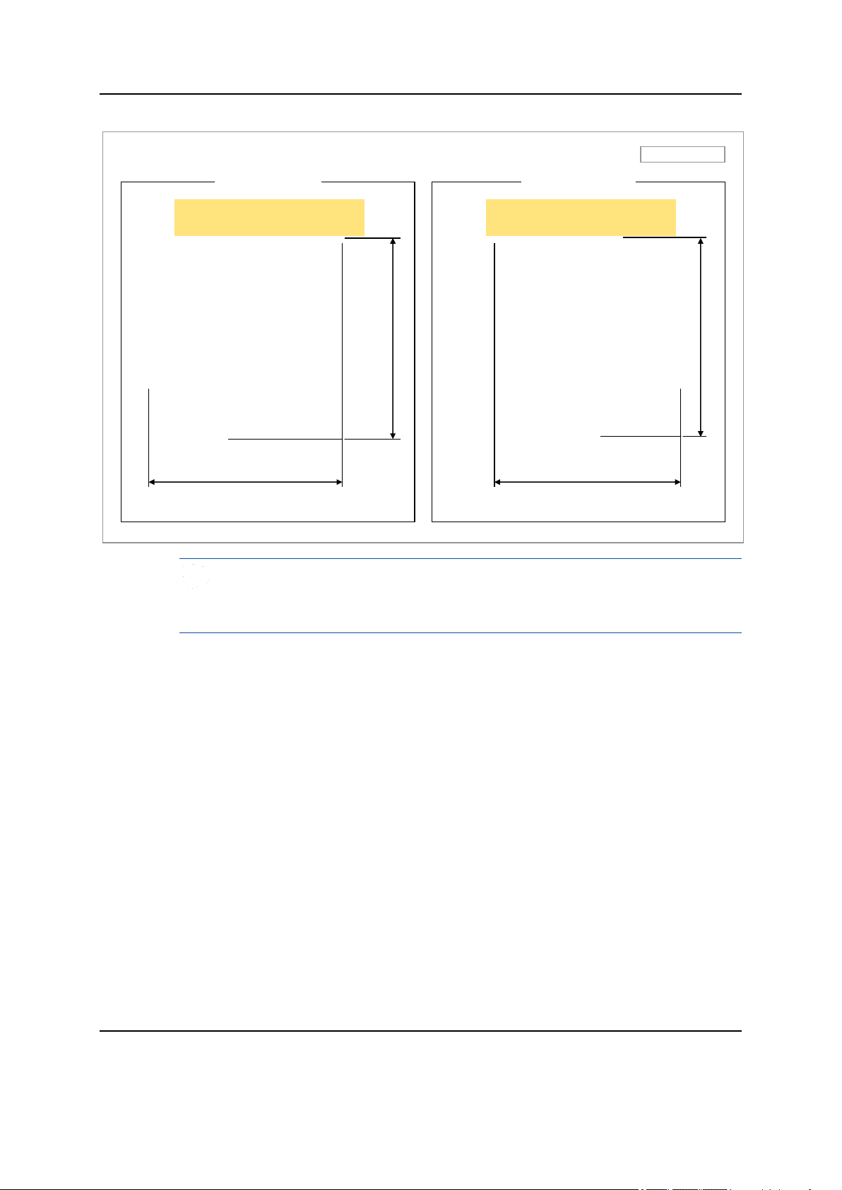
Figure 6. MMU Arrangement_Swivelling
Confidential
The dimensions of the front of the MMU change according to the tilt angle, and
the maximum dimensions are described in the figure below (MMU Arrangement_
Left, Right Swivelling 30°).
MT3204 Series Installation Manual v1.0 13
Copyright © 2018, All Rights Reserved.

Chapter 2 Installing System
Transporting and Unpacking
This section describes how to transport the items to the installation place and
provides the procedure to unpack cabinets and other components.
Bringing in Items
Ensure the following at each stage of transportation of the items:
Before moving a system, check storage place for the system and remove
obstacles in advance.
When carrying the system:
o Fasten the system firmly to the transport vehicle or carrier to prevent
damage to the system from a vibration or shock.
o Use an elevator to prevent accidents. However, if the system must be
carried by people, ensure there are enough people to carry the system.
The system must not be shocked physically.
Confidential
Unpacking
The system should be protected from dust, moisture, and static electricity.
To unpack the items, ensure the following:
The items must be packed until they reach the installation place.
The items are classified in accordance with each job specification and stored at
a place that does not interfere with working.
Unpacked systems must be installed immediately. If immediate installation of
the systems is not planned, the systems must be stored in the installation place
temporarily.
Unpack only external packing, leaving the internal packing in unpacked status.
Unpack the inner packaging after each system is placed on its installation
location.
Dispose by-products (packaging waste) in accordance with waste management
rules. Do not recycle the by-products.
MT3204 Series Installation Manual v1.0 14
Copyright © 2018, All Rights Reserved.
Chapter 2 Installing System
MMU Handle
[MMU Rear]
[Transporting the Packaging Box]
[Transporting the MMU]
Packaging Box
Handle
MMU Handling
When moving the MMU or its packaging box, use the handles located on both
sides of the MMU or its packaging box.
Lifting Hazard
Single person lift could cause injury. Get help when moving or lifting.
Figure 7. Transporting the MMU
Confidential
MT3204 Series Installation Manual v1.0 15
Copyright © 2018, All Rights Reserved.
 Loading...