

Samsung Msys 730 Service Manual
SERVICE
SAMSUNG FACSIMILE
Msys 730
Manual
SAMSUNG FACSIMILE CONTENTS
1. Precautions
2. Specifications
3. Disassembly and Reassembly
4. Troubleshooting
5. Exploded Views and Parts List
6. Block Diagram
7. Connection Diagram

ELECTRONICS
© Samsung Electronics Co.,Ltd. MAY
2002
Printed in Korea.
VERSION NO. : 1.00 CODE : JC-0073A
This service manual is also provided on the web,
the ITSELF system Samsung Electronics Co., Ltd.
“http://itself.sec.samsung.co.kr”

This manual is stated and
provided for service description.
All rights reserved. Any parts of the
information in this manual are prohibited
from free duplication, use or translation
without prior written approval except in
cases allowed by the Copyright Act.
Specifications are subject to change without
prior notice.
Copyright (c) 2002. 5.
Samsung Electronics Digital Printing CS Group
1-1
Samsung Electronics
1. Precautions
Please read the following carefully to prevent any accidents and not to damage the unit during service.
1-1 Safety Precautions
1-2 Precautions on Disassembly and Reassembly
1. Safety Precautions
There are some electric or machinery parts with safety
related property. If the parts replaced are different from
the original, the safety may not function. Even if the part
could allow higher voltage than that of the part used, do
not replace it and use a regular product clarified in specifications.
2. Be careful not to leave a switch, a cover or a safety device
out when reinstalling or assembling the product after
repair.
3. Replacing Precautions
Do not change or add parts as you like. You cannot benefit from such a remodeled product at your will during the
term of guarantee.
4. You must replace overheated or damaged parts or cords
with regular products. Please solve the problem causing
any damage or overheating and troubles beforehand.
Especially mind the safety on the part with this
mark.
You must use regular parts described in specifications for the parts inflammable and where the current can be flown. Otherwise any hazard such as
an electric shock or a fire could occur.
LASER STATEMENT (LASERTURVALLISUUS)
WARNING : NEVER OPERATE AND SERVICE THE PRINTER
WITH THE PROTECTIVE COVER REMOVED
FROM LASER/SCANNER ASSEMBLY. THE
REFLECTIVE BEAM, ALTHOUGH INVISIBLE, CAN
DAMAGE YOUR EYES.
Class 1 laser product
Luokan 1 laserlaite
Klass 1 laser apparat
Allonpituus 770-795nm
Teho 0.3mW±0.03mW
CAUTION
VORSICHT
ATTENTION
ATTENZIONE
PRECAUCION
CAUTION : Avoid exposure to invisible laser radiation when the
development unit is not installed.
INVISIBLE LASER RADIATION WHEN
THIS COVER OPEN. DO NOT OPEN
THIS COVER.
UNSICHTBARE LASERSTRAHLUNG,
WENN ABDECKUNG GEOFFNET.
NIGHT DEM STRAHLAUSSETZEN.
REYONNEMENT LASER INVISIBLE EN CAS
D’OUVERTURE. EXPOSITION DANGERUSE AU
FAISCEAU.
RADIAZIONE LASER INVISIBLE IN CASO DI
APERTURA. EVITARE L’ESPOSIZONE LA FASCIO.
REDIACION LASER INVISIBLE CUANDO SE
ABRE. EVITAR EXPONERSE AL RAYO.
Very careful precautions should be taken when replacing
parts. Before replacing, please check cables because you
cannot put the cables that you removed for replacing parts
into the proper place if you would not make sure of where
they were connected and in which condition.
Please do the following before disassembling
for a repair or replacement of parts.
1. Pull out paper cassette, printer cartridge installed.
Especially careful not to be scratched by the surface of
developer or not to expose them to light.
2. Turn the power switch off.
3. Take out the power plug, printer cable from the printer.
4. Use only the same type of part as original when replacing
parts.
5. Do not force to open or fasten plastic material components.
6. Be careful that small parts such as screws should not get
in the printer.
7. When disassembling, assembling, also observe small
components are located in place.
8. If you uncover and turn the machine over to replace some
parts, toner or paper particles may contaminate the LSU
window. Protect the LSU window with clean paper.
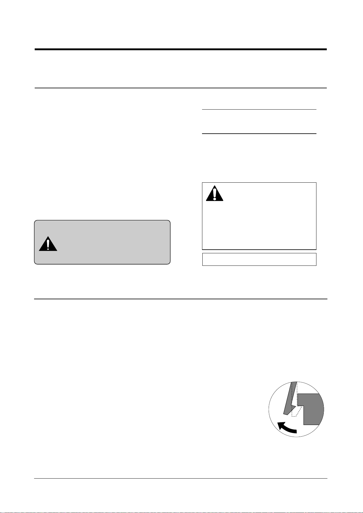
Releasing Plastic Latches
Many of parts are held in
place with plastic latches.
The latches break easily :
release them carefully.
To remove such parts,
press the hook end of the
latch away from the part to
which it is latched.

Certain semiconductor devices can be easily damaged by
static electricity. Such components are commonly called
“Electrostatically Sensitive (ES) Devices”, or ESDs.
Examples of typical ESDs are: integrated circuits, some field
effect transistors, and semiconductor “chip” components.
The techniques outlined below should be followed to help
reduce the incidence of component damage caused by static electricity.
1. Immediately before handling a semiconductor component or semiconductor-equipped assembly, drain off any
electrostatic charge on your body by touching a known
earth ground. Alternatively, employ a commercially available wrist strap device, which should be removed for your
personal safety reasons prior to applying power to the unit
under test.
2. After removing an electrical assembly equipped with
ESDs, place the assembly on a conductive surface, such
as aluminum or copper foil, or conductive foam, to prevent electrostatic charge buildup in the vicinity of the
assembly .
3. Use only a grounded tip soldering iron to solder or desolder ESDs.
4. Use only an “anti-static” solder removal device. Some solder removal devices not classified as “anti-static” can
generate electrical charges sufficient to damage ESDs.
5. Do not use Freon-propelled chemicals. When sprayed,
these can generate electrical charges sufficient to damage ESDs.
6. Do not remove a replacement ESD from its protective
packaging until immediately before installing it. Most
replacement ESDs are packaged with all leads shorted
together by conductive foam, aluminum foil, or a comparable conductive material.
7. Immediately before removing the protective shorting
material from the leads of a replacement ESD, touch the
protective material to the chassis or circuit assembly into
which the device will be installed.
8. Maintain continuous electrical contact between the ESD
and the assembly into which it will be installed, until completely plugged or soldered into the circuit.
9. Minimize bodily motions when handling unpackaged
replacement ESDs. Normal motions, such as the brushing together of clothing fabric and lifting one’s foot from a
carpeted floor, can generate static electricity sufficient to
damage an ESD.
1-3 ESD Precautions
Precautions
1-2
Samsung Electronics
CAUTION:
Be sure no power is applied to the chassis or circuit, and observe all other safety precautions.
Precautions
1-3
Samsung Electronics
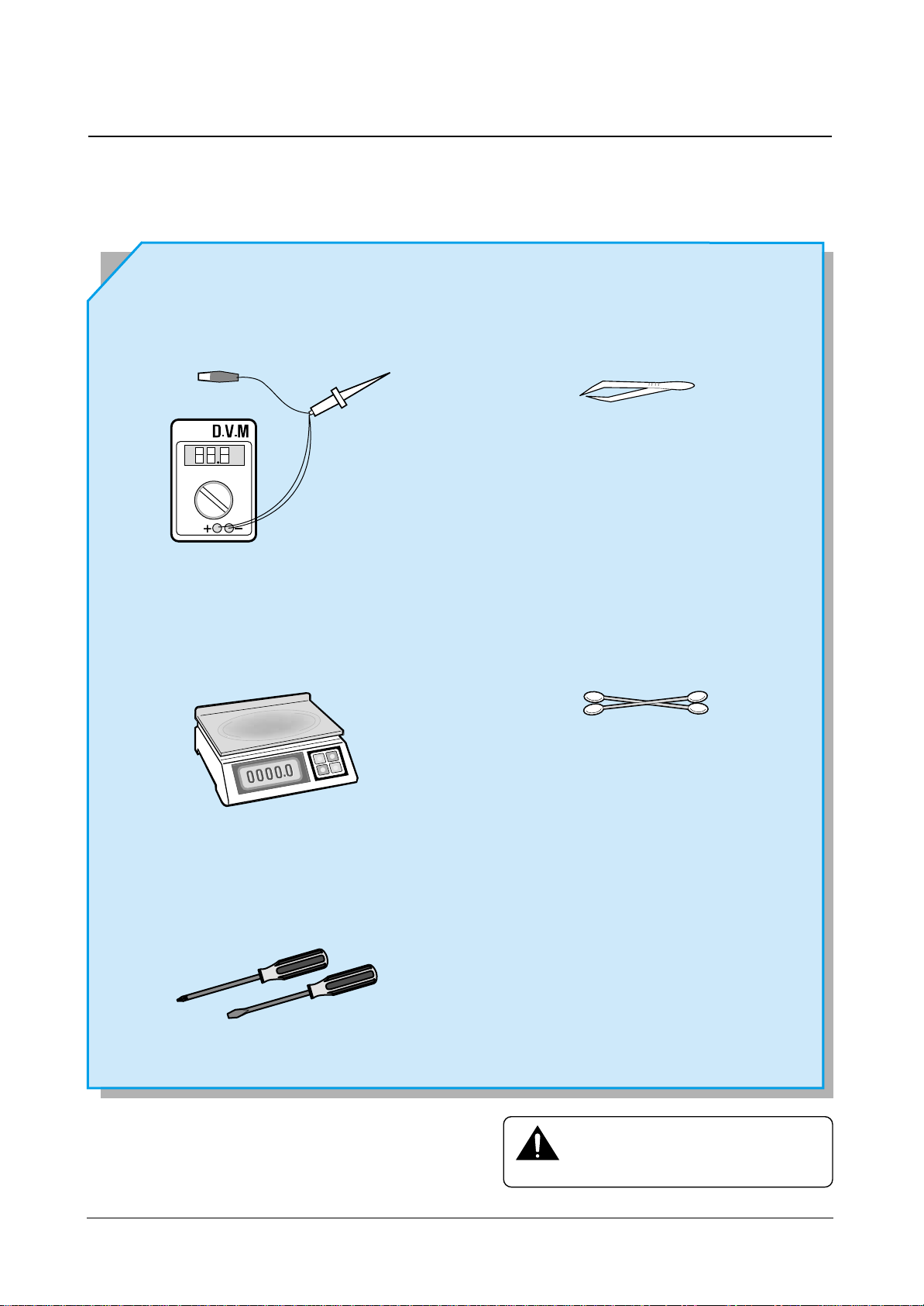
1-4 Tools for Troubleshooting
The following tools are recommended for safe and smooth troubleshooting described in this service manual.
DVM(Digital Volt Meter)
Standard : Indicates more than 3 digits.
Electronic Scale
Standard : Equipment to check the weight of con-
sumables(toner cartridge) . (The gram unit
can be measured.)
Driver
Standard: "-" type, "+" type (M3 long, M3 short, M2
long, M2 short)
Pinset
Standard : For general home use, small type.
Cotton Swab
Standard : For general home use, for medical ser-
vice.
Cleaning Equipments a IPA(Isopropyl
Alcohol) dry cloth or a soft stuff neutral
detergent.
Mind your hands not to be touched when
you disassemble and reassemble PBAASS'Y,
such as the main board, SMPS, HVPS.
Note
2. Specification
2-1 Facsimile
Machine type Desk Top
Applicable line Public Switched Telephone Network (PSTN) or behind PABX
Compatibility CCITT Group 3
Data coding MH/MR/MMR
Modem speed
33600/31200/28800/26400/24000/21600/19200/16800/
14400/12000/9600/7200/4800/2400 bps
Transmission speed Approx. 6 sec.(14.4K,ECM,4% Letter)
Effective scanning width 8.2 inches (208 mm)
Effective printing width 8.2 inches (208 mm : LTR)
Scanning method Sheet-fed scanning using a Contact Image Sensor (CIS)
Memory 5 MByte
Halftone 256 levels
Printing speed 8 PPM (Letter size)
Automatic document feeder 50 pages (75g/m2, 20lb : 0.09 ~ 0.10 mm thickness)
Documents size
Width 5.8 to 8.5 inches (148 to 216 mm)
Length Single page : 5 to 59 inches (128 to 1,500 mm)
Multi pages : 8.3 to 11.7 inches (279 to 297 mm)
Weight Single page : 12.5 to 32 lb (50 to 100g/m
2
) (0.07 to 0.15 mm)
(thickness) 20 pages: 12.5 to 28 lb (50 to 90g/m
2
) (0.07 to 0.13 mm), Uncoated paper
50 pages : 20 lb (75g/m
2
) (max 0.1 mm), Uncoated paper
One-touch dial :
Registration for 38 numbers
Speed dialing Registration for 150 numbers
LCD : 16 characters x 2 lines
2-2 SCANNER
Scanning Method : Sheet-fed scanning by CIS and feeding of the document by a
stepping motor
Resolution Horizontal 11.8 lines/mm (300 dpi)
Vertical STANDARD : 3.85 lines/mm (98 Lpi)
FINE : 7.7 lines/mm (196 Lpi)
SUPER FINE : 11.8 lines /mm (300 Lpi)
Gray Scale : 256 shades
Scanning period : STANDARD : 2.5 ms/line
FINE : 2.5 ms/line
SUPER FINE : 2.5 ms/line
Samsung Electronics 2-1

2-2 Samsung Electronics
2-3 Printer
Print Speed 8 PPM (A4 Size, 5% Charcter Pattern) : At Copy Mode
Resolution 600 X 600 DPI
Source of Light Laser Diode(LSU)
Print Method Non-impact Electrophotography, Laser Beam
Feed Method Multi-Purpose Feeder and Manual
Feed Reference Side Reference Loading
Paper Size Cassette Type Normal Paper : A4,Letter,Legal,B5,Executive
A5 (for manual)
Length 148 ~ 356mm
Width 98 ~ 216mm
Paper Weight For MPF 60 ~ 90g/m
2
For Manual 60 ~120g/m
2
Paper Capacity MPF 250 Sheets (based on 75g/m2)
Manual Slot 1 Sheet
Paper Stacker Capacity Face up : 150 Sheets (75g/m2,20 lb)
Warming up Time About 20 sec
First Printing Time Stand-By About 25 sec
Power Save Mode About 40 sec
Power Rating AC 110V ~127V ± 15% 50/60Hz ± 3Hz,
AC 220V ~ 240V ± 15% 50/60Hz ± 3Hz
Power Consumption Max. 210Wh
Stand-by 50Wh
Avg. 13Wh
Power Saving Consumption Sleeping Mode
Certification & Compliance FCC, cUL, CE, CB, IC CS-03
Acoustic Noise Standby Less than 36dB
Operating Less than 50dB
Toner Cartridge One-Cartridge type
Expected Life Span 100,000 Sheets
Operating Environment Temperature : 10 ~ 30°C , Humidity : 30 ~ 80%RH
Storage Environment Temperature : 0 ~ 35°C , Humidity : 20 ~ 95%RH
Weight SET Net : 9 kg Gross : 14.3 kg
SCF Net : 4.8 kg Gross : 6.0 kg
External Dimension 386(W) X 405(D) x 270(H)mm
Developer Life Span 5% Pattern,Min. 6,000 Sheets
Developing Non-magnetic Contact Developing
Charging Conductive Roller Charging
Density Adjustment Dark, Medium
Toner Supply Method Exchanging Toner Cartridge
New Developer Checkable YES
Transfer System Pre-transfer By LED & Conductive Roller Transfer
Fusing System Temperature & Pressure
OZONE Emission Max. 0.1 PPM(8 Hours)
Specification

Samsung Electronics 2-3
Specification
2-4 Quality
Conditions
Paper Normal Paper , 75g/m
2
Environment Temperature : 20 ~ 25°C
Humidity : 40 ~ 60%
Print Quality Image Density Min. 1.3
Min. 1.0(Temperature : 10 ~ 15°C) ,Samsung Paper
Background Max. 0.2
Uniformity Max. 0.2(Including Continuous Print)
Fusing Min. 75% (All Black)
Start Position Top : 4.23mm ± 2, Side : 4mm ± 2 From Left
Skew Top : Max. ± 1.5mm/200mm
Side : Max. ± 2.0mm/250mm
Orthogonality ± 1.0mm
Horizontal Scan ± 0.6mm/200mm
(Bowed Line Skew : Pattern 1)
Special Paper Exception Image Density : Min 1.0 (Envelope)
Fusing : Min. 70% (All Black)
(Envelope/OHP/Postcard)
Paper Jam Less than 1/1,000(75g/m
2
Paper)
Paper Curl First : Less than 16mm (10 Sheets, 75g/m2Paper)
After Cooling : Less than 16mm (10 Sheets, 75g/m2Paper)
Reliability Insulation Resistance Less than 10 MΩ (at DC 500V)
Dielectric Strength AC 1000V (DC 1420V), 10mA
Ground Continuous Less than 0.1Ω
Voltage DIP Rated Voltage ± 15%
AC Impulse Noise AC 1000V 10, 100, 200, 400, 1000ns Rated Power
Leakage Current Less than 3.5mA
Surge 6 KV, 500A
OZONE Emission Less than 0.1 ppm (8 Hours)
Top Cover Open Isolating the input power of the LSU,
High Voltage Part, and Fuser
Overcurrent Protect Fuse inside the Engine Controller
Fusing System Trouble Sensing .The temperature doesn’t rise to the specific
temperature in the specific time.
.The temperature is too high.
Overheat Sensing 240 ~ 250°C (The thermostat cuts off the Fuser from the
power.)
Thermistor Open Sensing : Without the initial temperature
change of the Fuser
2-4 Samsung Electronics
Specification
2-5 SMPS (Switching Mode Power Supply)
Input (AC) AC Input Voltage American
Minimum 90V
Typical 120V
Maximum 135V
Max. AC Input Currents 3Amps
Max. Inrush Current) 40 Ap-p (at 25°C)
Output (DC) Line Regulation 24V ± 10%
12V ± 5%
Road Regulation -12V ± 5%
5V ± 5%
Ripple Noise 24V : Peak 500mVp-p
12V : Peak 500mVp-p
-12V : Peak 500mVp-p
5V : Peak 300mVp-p
Over Current Protect 24V : 2.7A ± 10% (by Circuit)
5V : 3A ± 10% (by Circuit)
Over Voltage Protect 24V : 33V
5V : 5.6V

Disassembly and Reassembly
3-1
Samsung Electronics
3. Disassembly and Reassembly
3-1 General Precautions on Disassembly
When you disassemble and reassemble components, you must use extreme caution. The close proximity of cables to
moving parts makes proper routing a must.
If components are removed, any cables disturbed by the procedure must be restored as close as possible to their original positions. Before removing any component from the machine, note the cable routing that will be affected.
Whenever servicing the machine, you must perform as follows:
1. Check to verify that documents are not stored in memory.
2. Be sure to remove the toner cartridge before you disassemble parts.
3. Unplug the power cord.
4. Use a flat and clean surface.
5. Replace only with authorized components.
6. Do not force plastic-material components.
7. Make sure all components are in their proper position.
3-2 Releasing Plastic Latches
Many of the parts are held in place with plastic latches. The latches break easily; release them carefully.
To remove such parts, press the hook end of the latch away from the part to which it is latched.
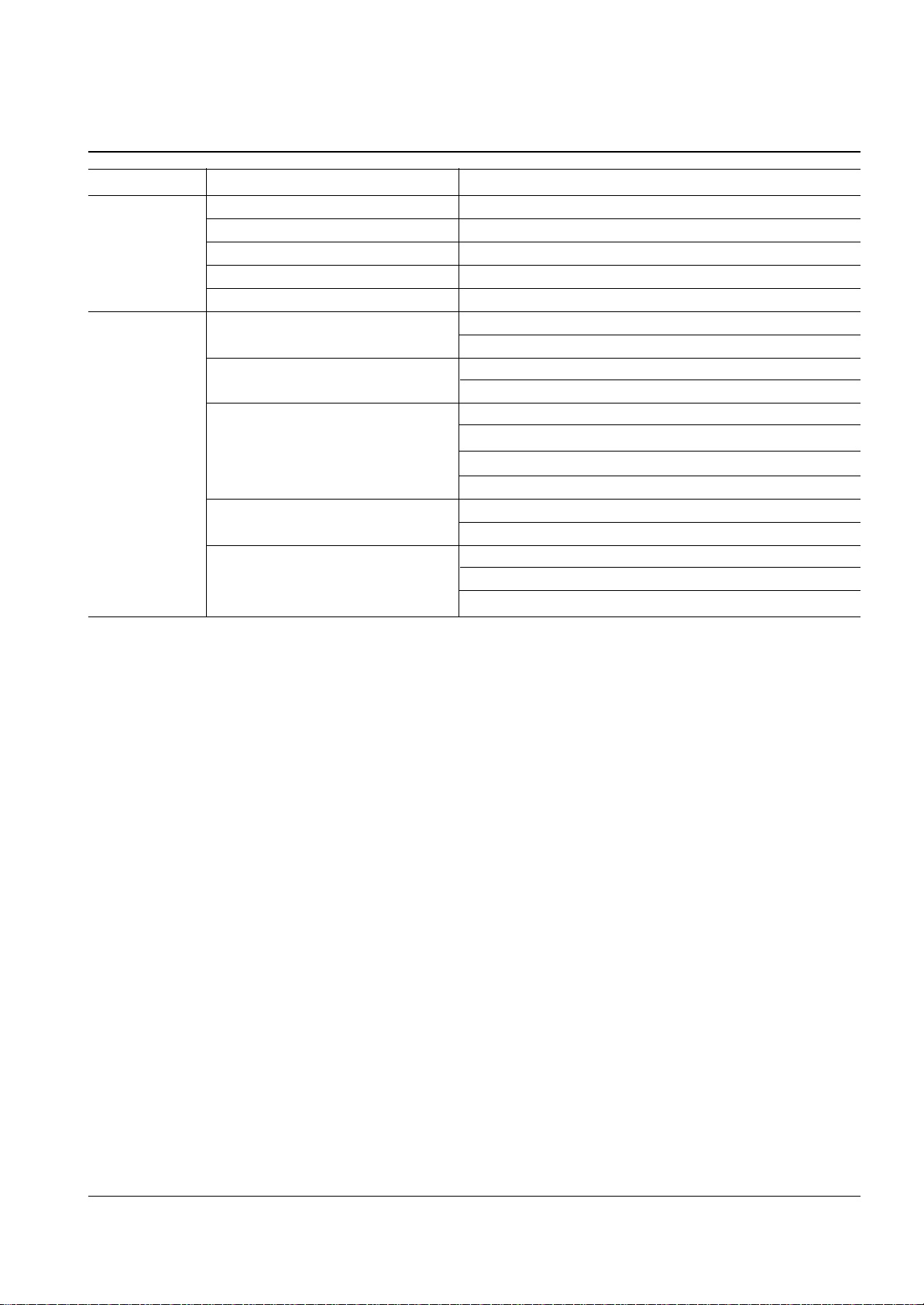
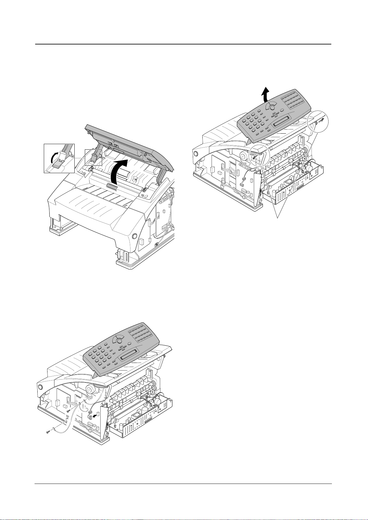
1. Open the OPE panel, then set the support-OPE to
the OPE panel.
2. Push the bushing on the both ends of the roller
slightly inward, then rotate it until it reaches the slot.
Then lift the roller out.
Note: Check the roller for any dirt. If dirty, wipe it off with
soft cloth dampened with water. If the roller is heavily worn, replace it with a new one.
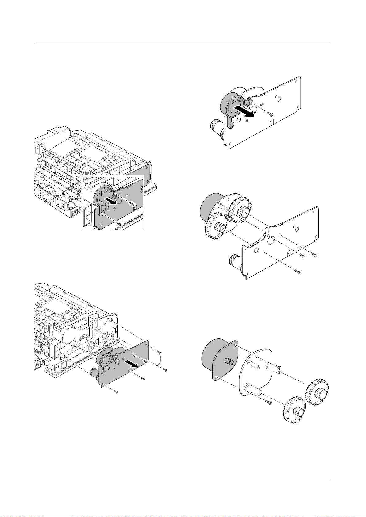
1. Open the front cover, and release one end of the
roller using a proper tool as shown in the square.
2. Pull the other end of the roller slightly inward, then lift
it up.
Disassembly and Reassembly
3-2
Samsung Electronics
3-3 White Roller
Bushing
Transfer roller
3-4 Transfer Roller
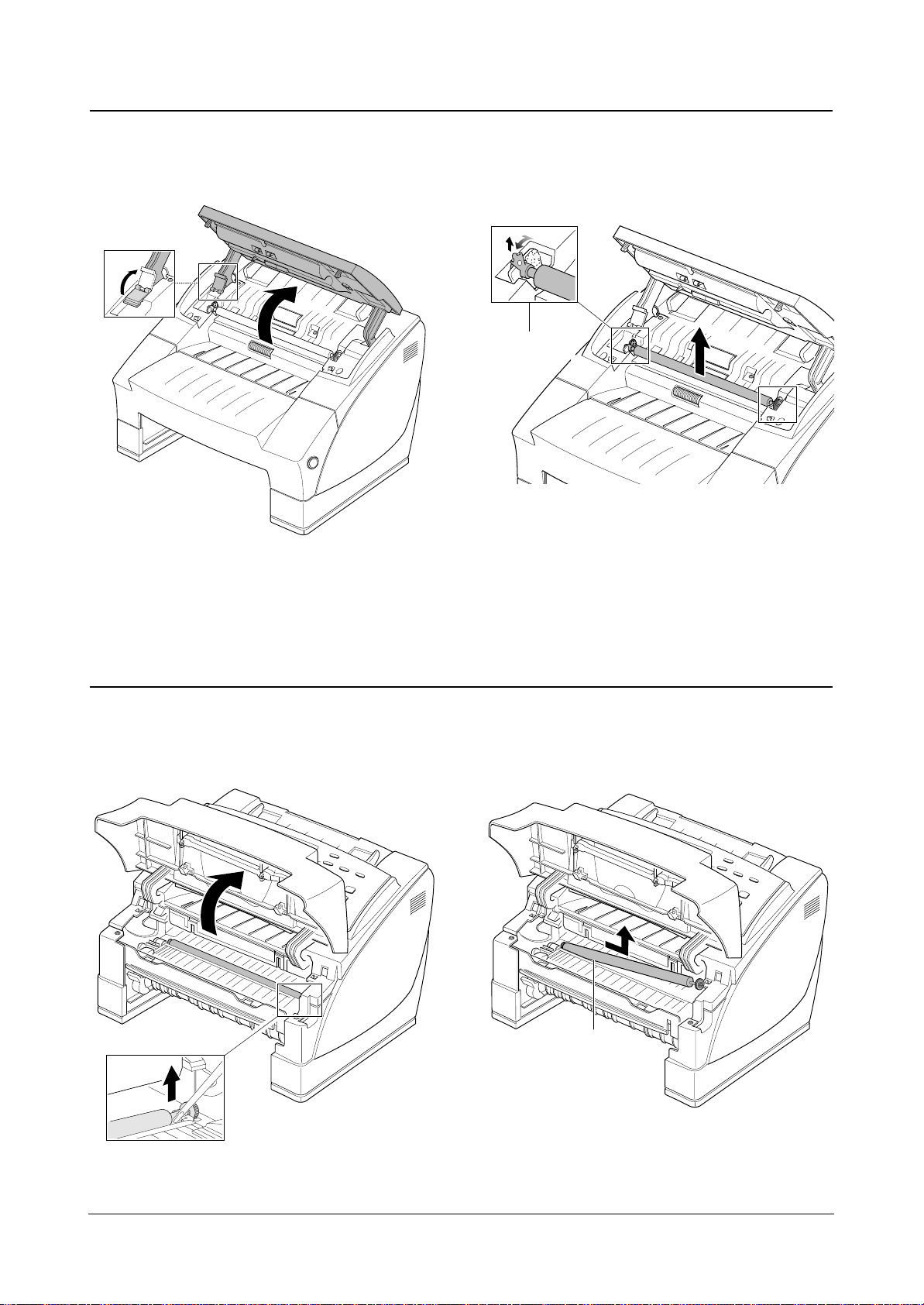
1. Remove four screws, unplug one harness, then
remove the rear cover.
2. If you want to remove the dummy fan from the rear
cover, remove two screws and release two latches,
then take it out.
1. Before you remove the cover, you should remove:
– Rear cover (see page above)
2. Open the front cover, remove one screw, then
remove the left side cover.
Disassembly and Reassembly
3-3
Samsung Electronics
3-5 Rear Cover
3-6 Left Side Cover
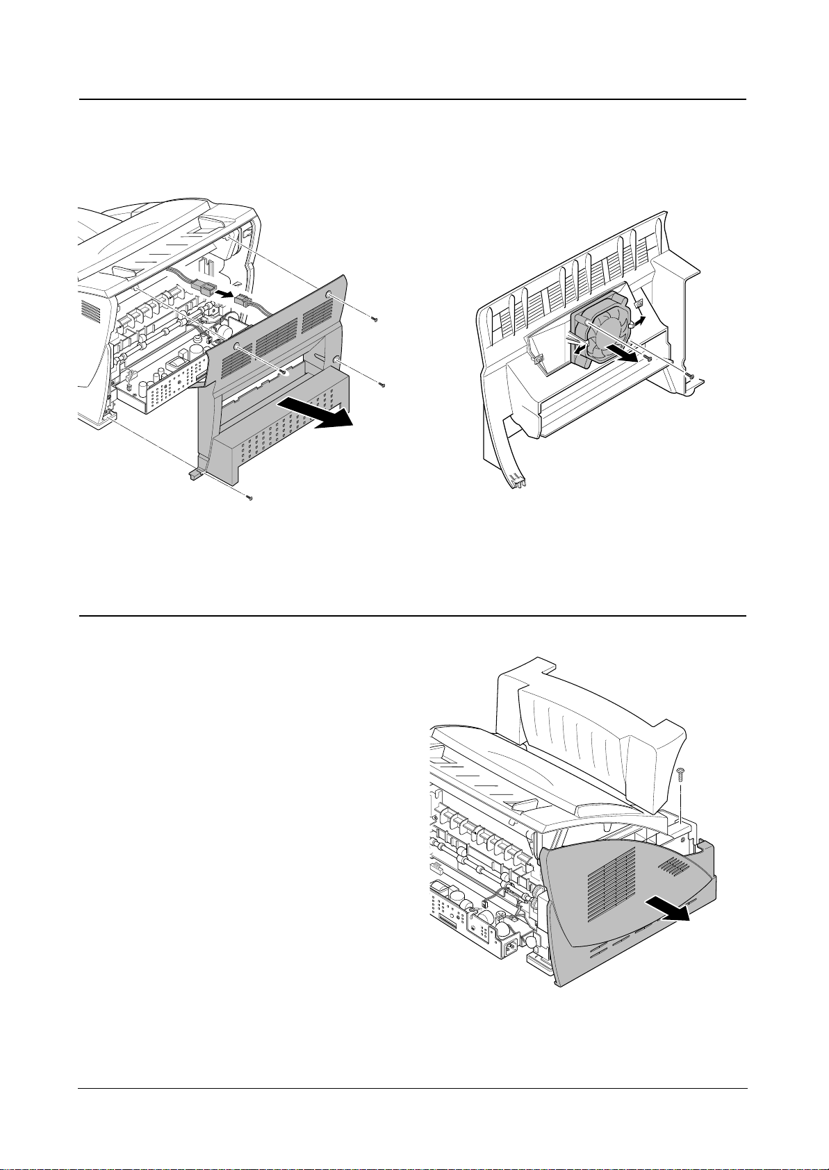
1. Before you remove the cover, you should remove:
– Rear cover (see page 3-3)
2. Open the front cover, and remove one screw.
3. Remove three screws, then pull the plate slightly
toward you to release the side cover.
4. Unplug the speaker harness from the main board,
then remove the right side cover.
5. If you remove the fan from the side cover, remove
two screws, then take it out.
Disassembly and Reassembly
3-4
Samsung Electronics
When you reassemble
the fan, make sure
that the fan is placed
correctly.
3-7 Right Side Cover
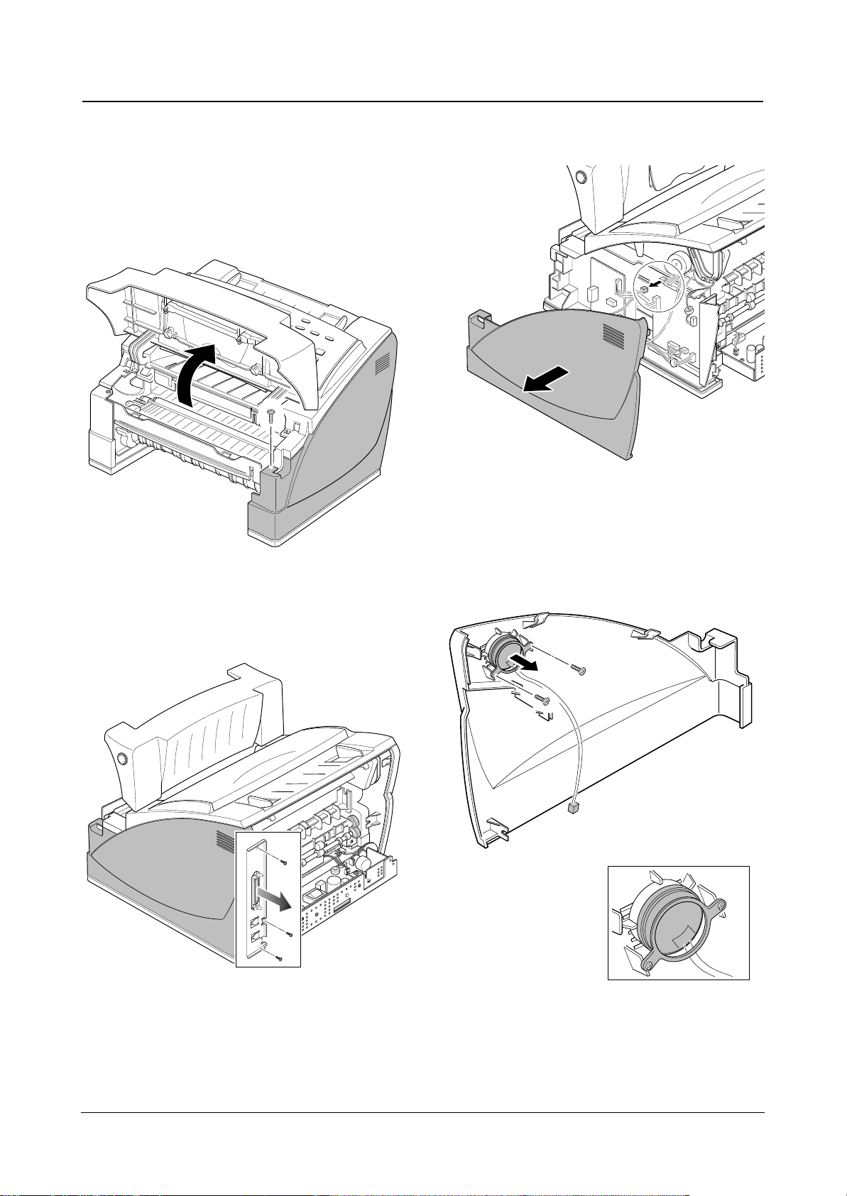
1. Before you remove the cover, you should remove:
– Rear cover (see page 3-3)
– Left/Right side covers (see page 3-3, 3-4)
2. Open the OPE panel, then set the support-OPE to
the OPE panel.
3. From the right side of the main body, remove two
ground screws and unplug one OPE harness. .
4. To unlatch the OPE ass’y, spread the both ends of
the OPE ass’y shown in circles in the figure below,
then remove the OPE ass’y.
Disassembly and Reassembly
3-5
Samsung Electronics
3-8 OPE Assembly
Spread the both ends of the OPE ass’y.
Disassembly and Reassembly
3-6
Samsung Electronics
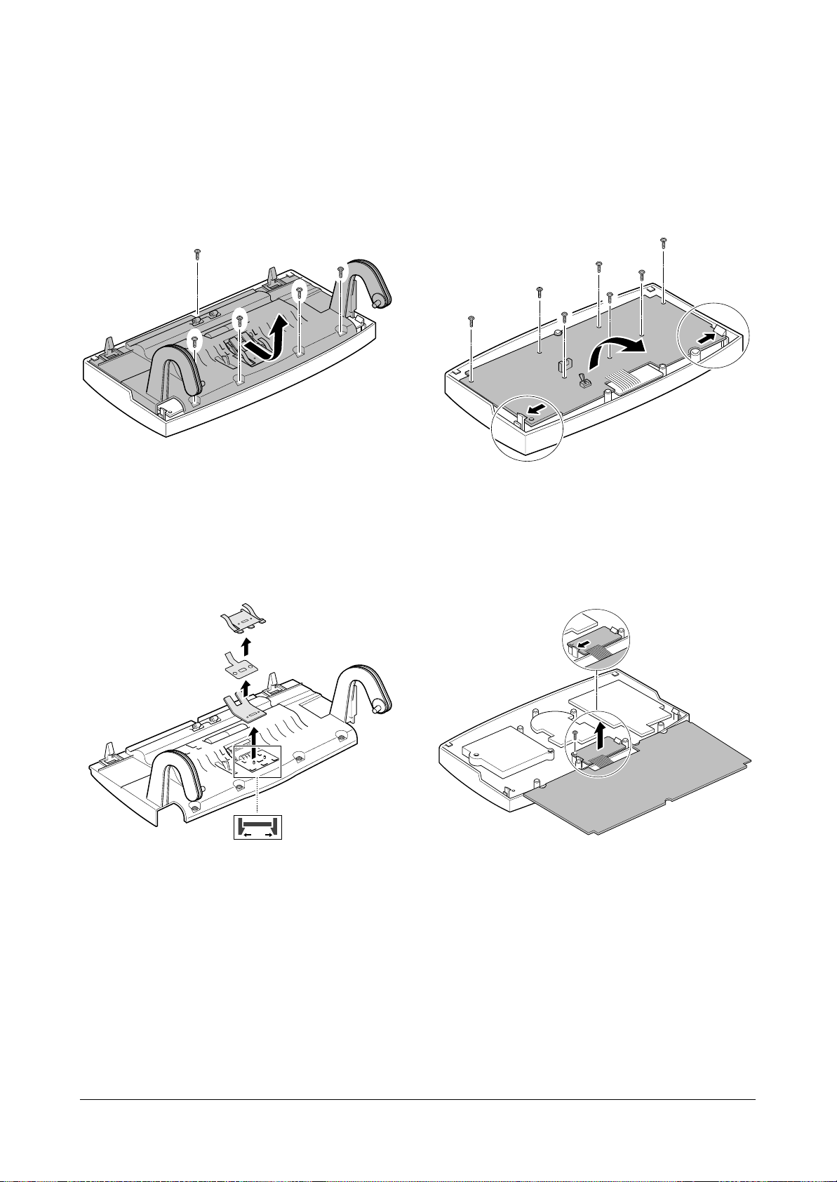
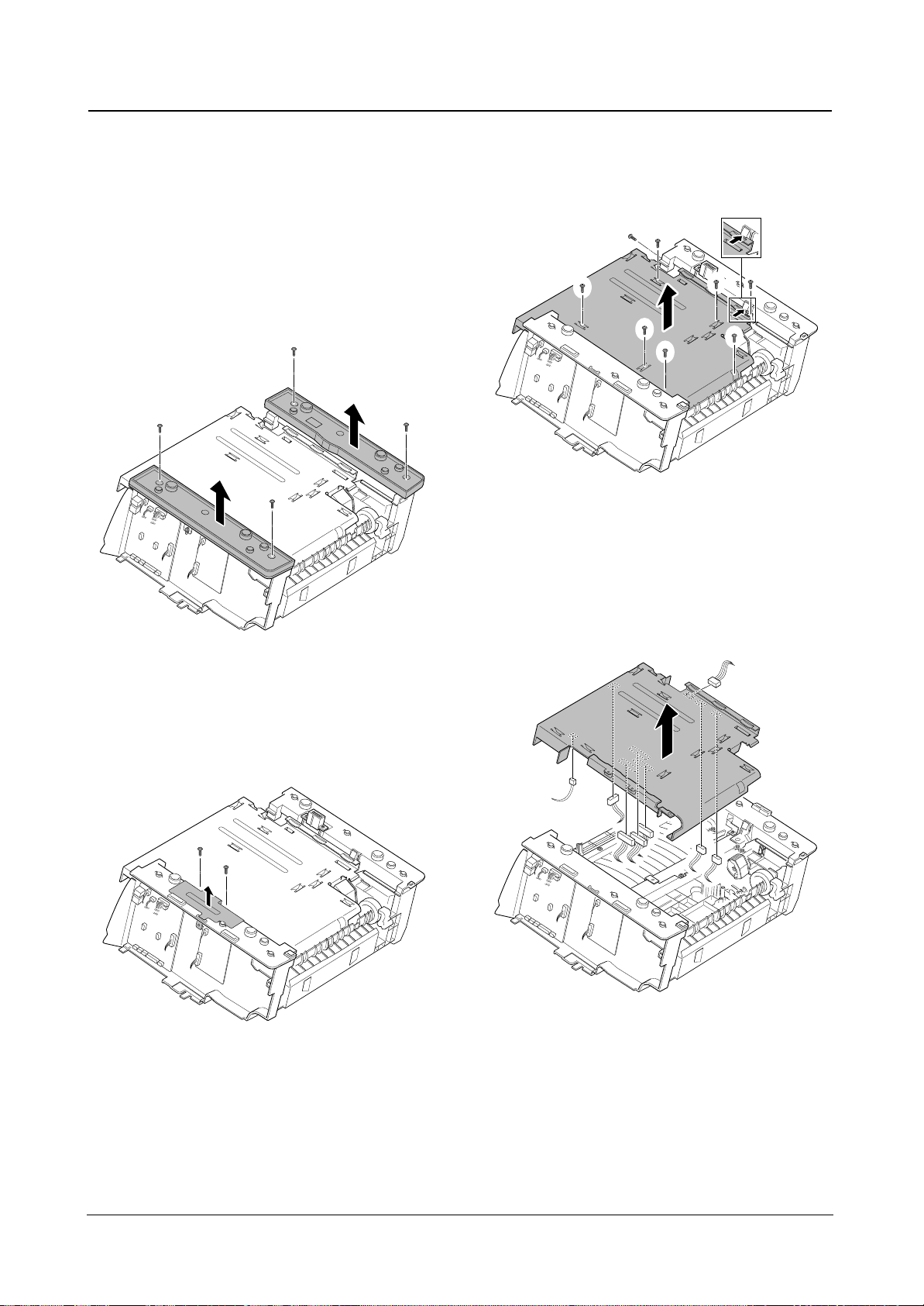
ADF Rubber on the OPE Ass’y
1. Remove five screws, then remove the scan upper
frame.
2. To unlatch the ADF rubber, push the plastic latches
on the ADF rubber from the bottom of the OPE ass’y.
Then remove the ADF rubber..
OPE PBA on the OPE Ass’y
1. Remove seven screws, release the plastic latches
securing the board, then turn the board upside down.
2. Remove a screw and release one of the latches
securing the LCD board, then remove the OPE
board with the LCD board.
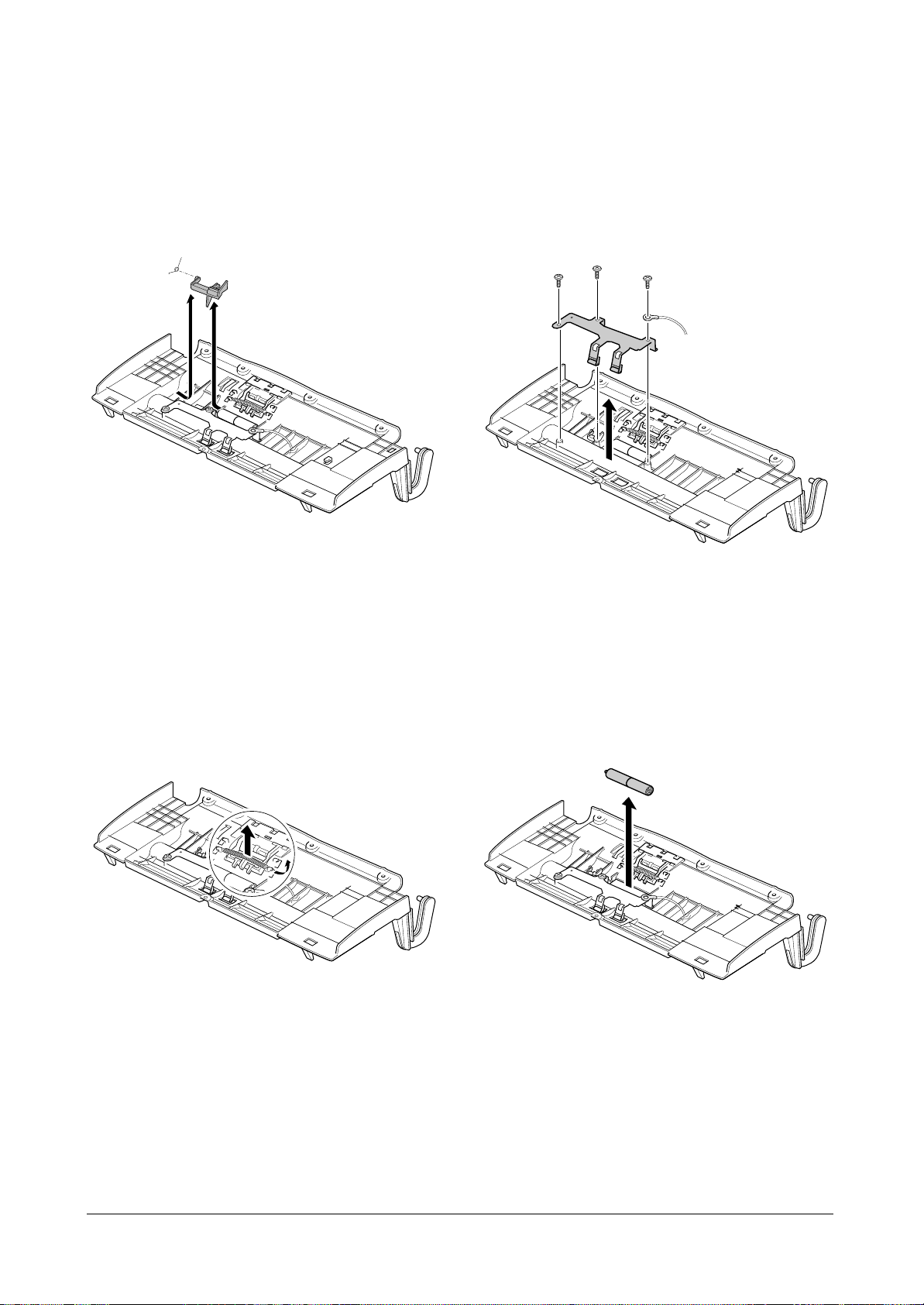
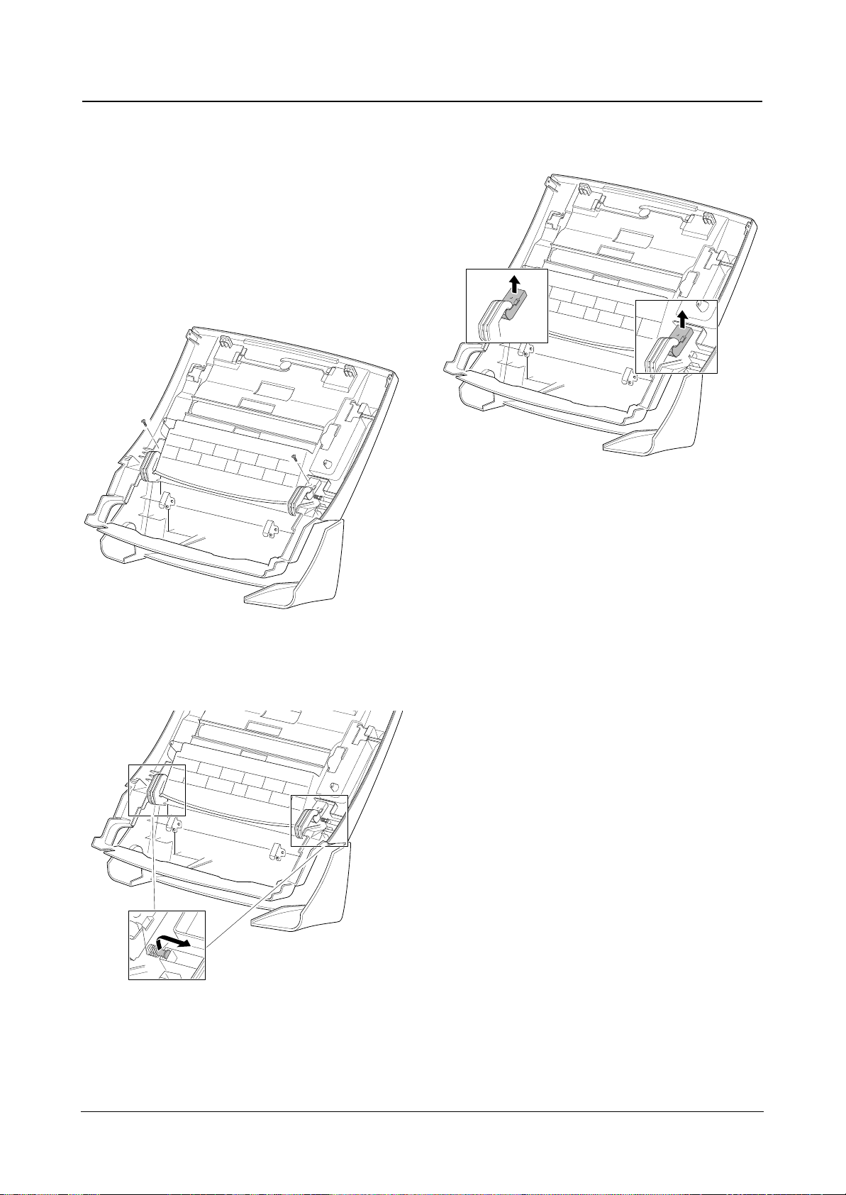
Lever Sensor on the OPE Ass’y
Squeeze the both ends of the lever sensor and lift it up.
Spring on the OPE Ass’y
Release one end of the spring and take it out from the
OPE ass’y.
Pinch Spring on the OPE Ass’y
Remove three screws securing the pinch spring then
take it out.
Pinch on the OPE Ass’y
Remove the pinch from the OPE ass’y.
Disassembly and Reassembly
3-7
Samsung Electronics
Disassembly and Reassembly
3-8
Samsung Electronics
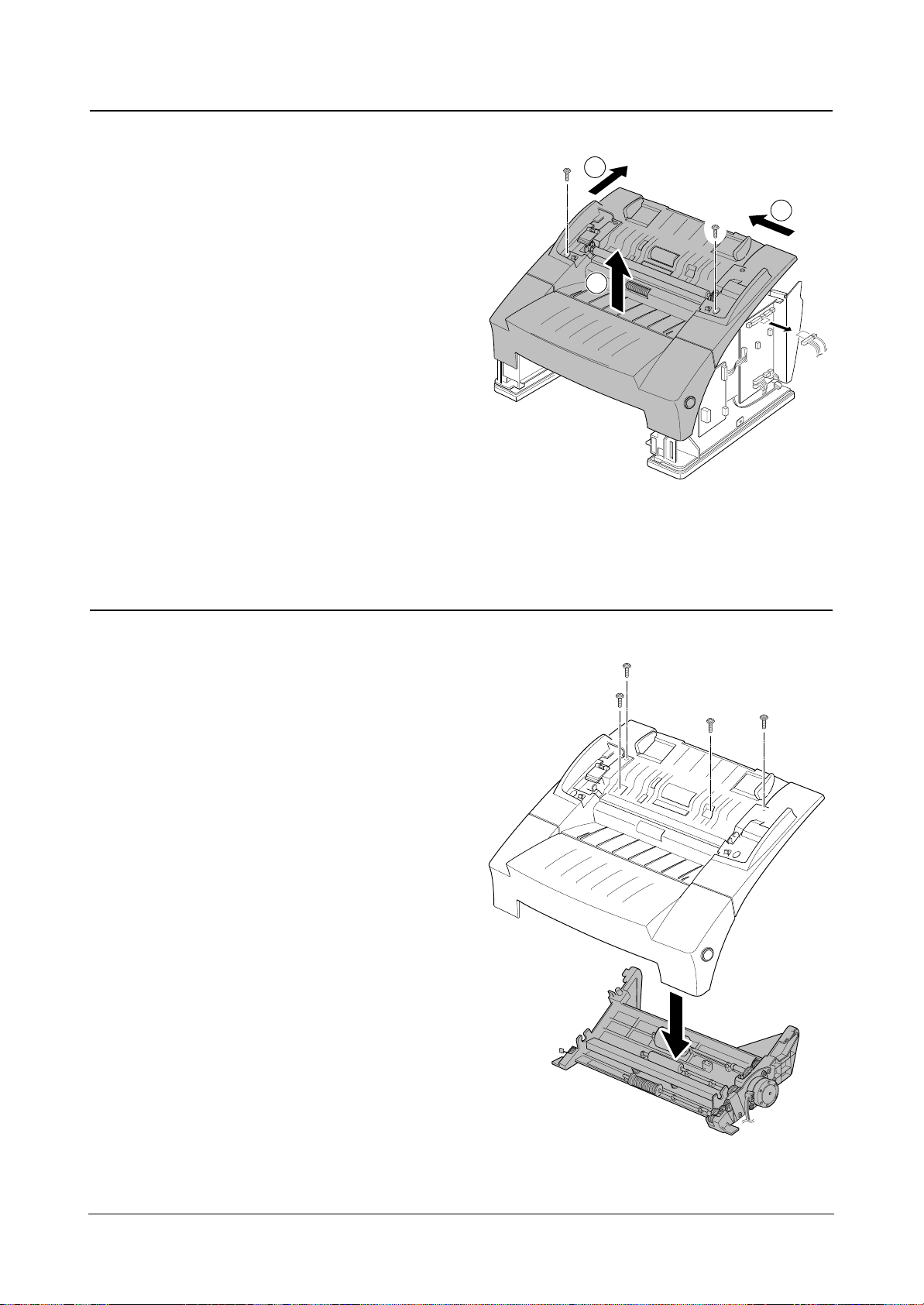
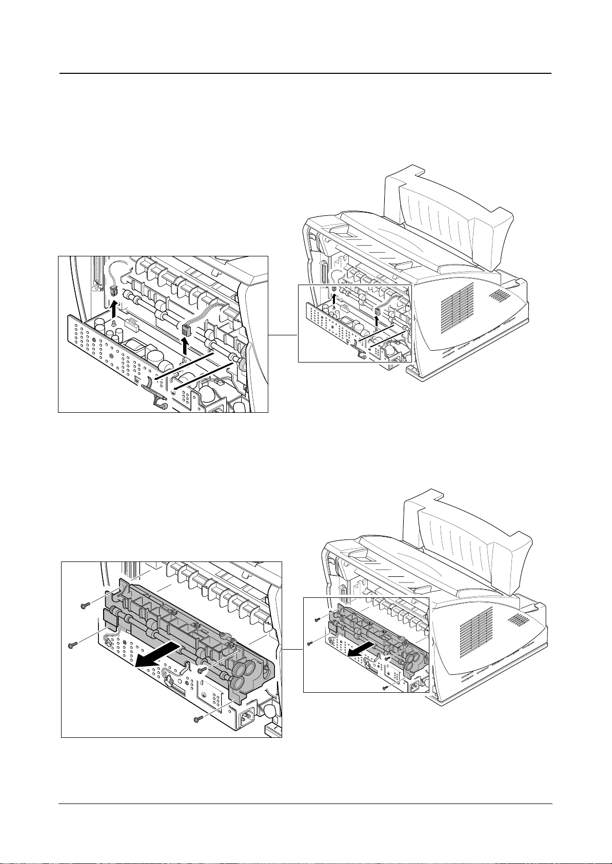
1. Before you remove the scan lower frame, you should
remove:
– Rear cover (see page 3-3)
– Left/Right side covers (see page 3-3, 3-4)
– Top Assembly (see page above)
2. Remove four screws and remove the scan lower
frame.
3-10 Scan Lower Frame
3-9 Top Assembly
1. Before you remove the cover, you should remove:
– Rear cover (see page 3-3)
– Left/Right side covers (see page 3-3, 3-4)
– OPE ass’y (see page 4-8)
2. Remove two screws and unplug two connectors from
the main board, then remove the Top ass’y pushing
in the direction of the arrows in order.
1
2
3
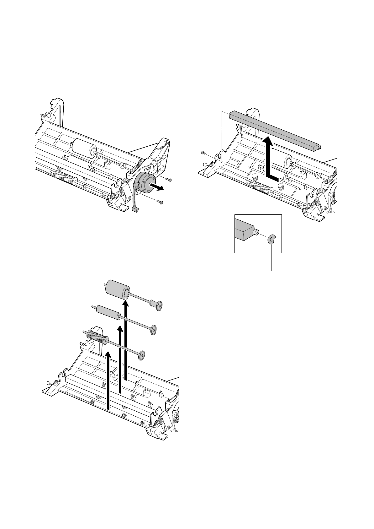
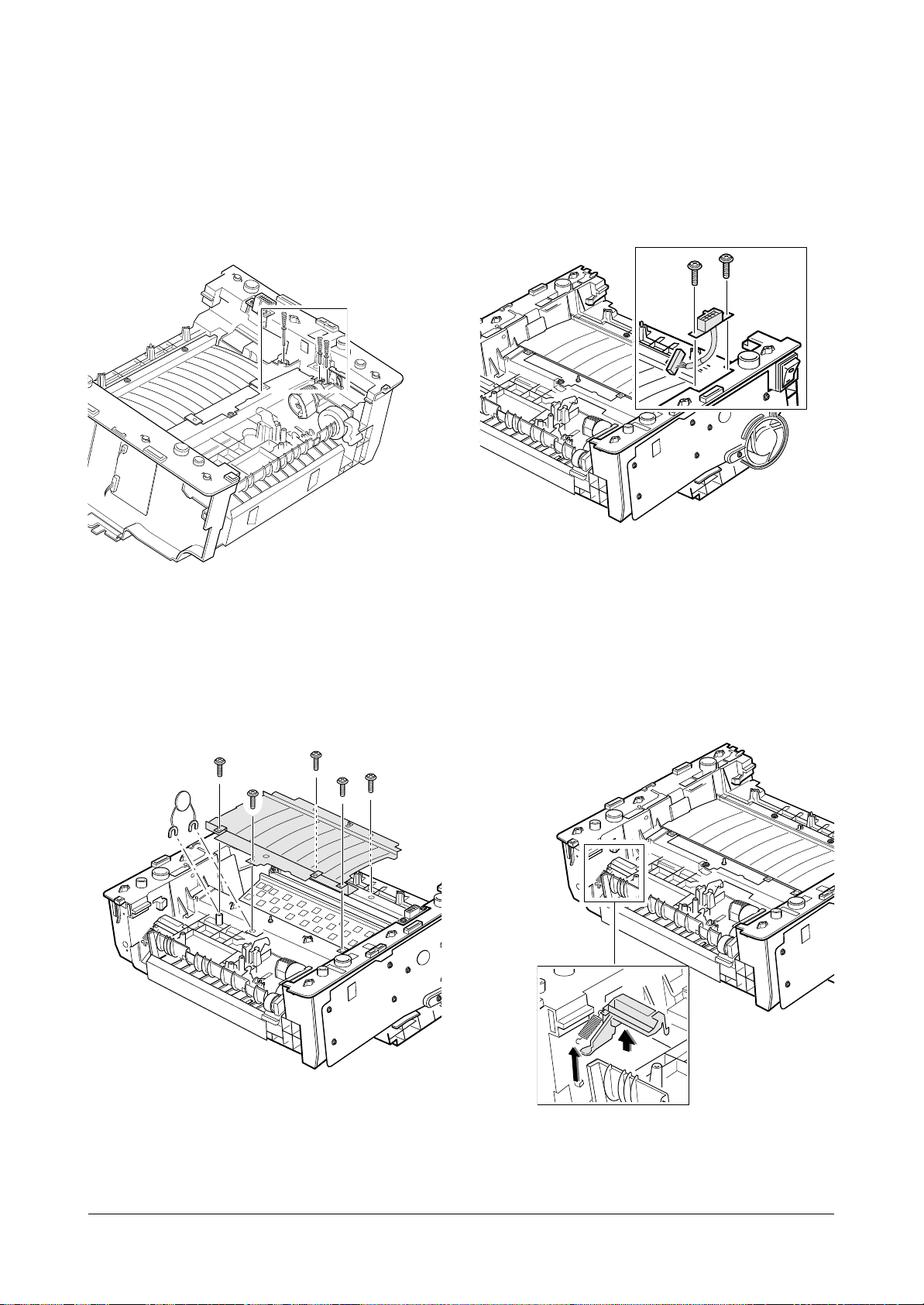
Scan Motor on the Scan Lower Frame
Remove two screws, and remove the scan motor.
Rollers on the Scan Lower Frame
Remove rollers.
CIS on the Scan Lower Frame
Remove one screw, slide the CIS slightly in the direction
of arrow, then lift it up.
Disassembly and Reassembly
3-9
Samsung Electronics
When you reassemble the CIS,
be careful for the direction of
this part.
1. Before you remove the covers, you should remove:
– Rear cover (see page 3-3)
– Left/Right side covers (see page 3-3, 3-4)
– OPE assembly (see page 3-5)
– Top assembly (see page 3-8)
– Scan lower frame (see page 3-8)
2. Remove two screws.
3. Remove shafts and springs connecting the two cov-
ers.
4. Remove the left and right hinge shafts. Now the two
covers can be separated.
Disassembly and Reassembly
3-10
Samsung Electronics
3-11 Main Cover and Front Cover
Disassembly and Reassembly
3-11
Samsung Electronics
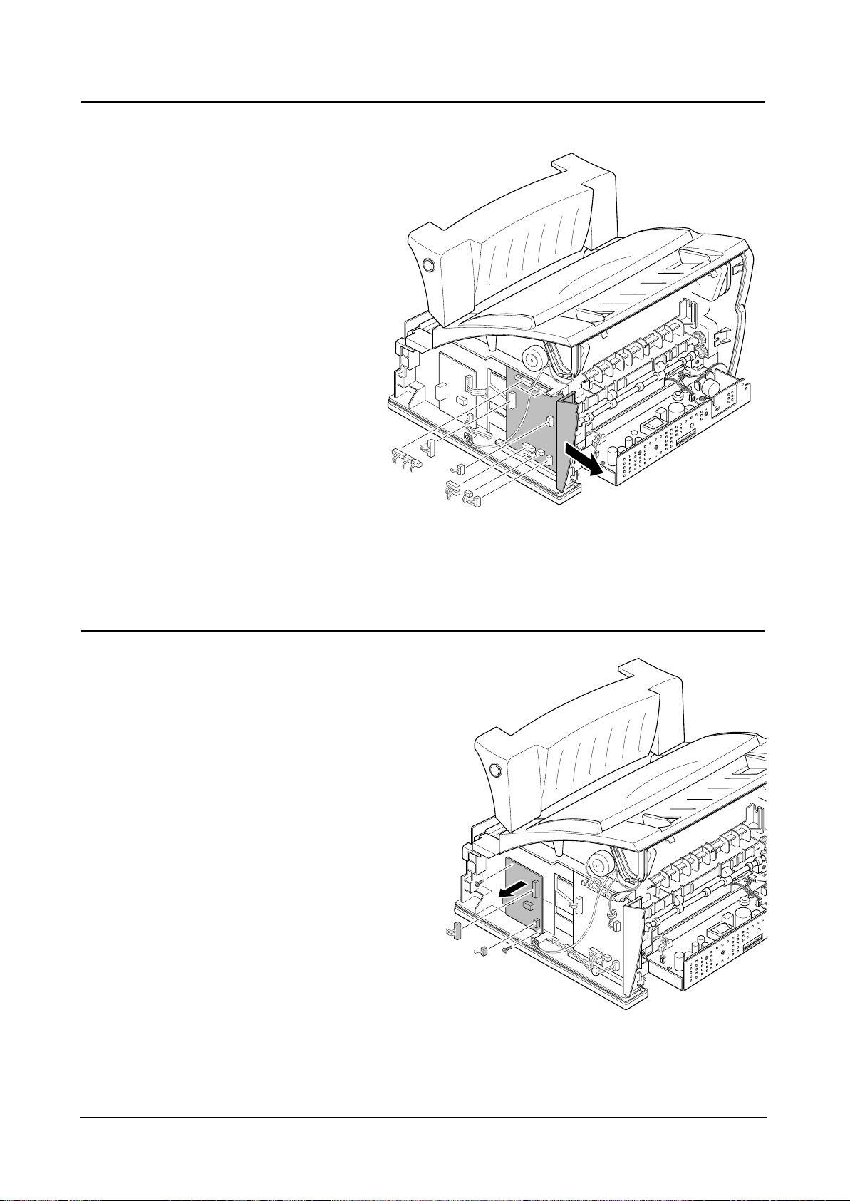
3-12 Main Board
1. Before you remove the main board, you should
remove:
– Rear cover (see page 3-3)
– Right side cover (see page 3-4)
2. Unplug all connectors from the main board, then
remove the board.
3-13 LIU Board
1. Before you remove the LIU board, you should
remove:
– Rear cover (see page 3-3)
– Right side cover (see page 3-4)
2. Remove two screws, then unplug all connectors from
the LIU board, then remove the board.
Disassembly and Reassembly
3-12
Samsung Electronics
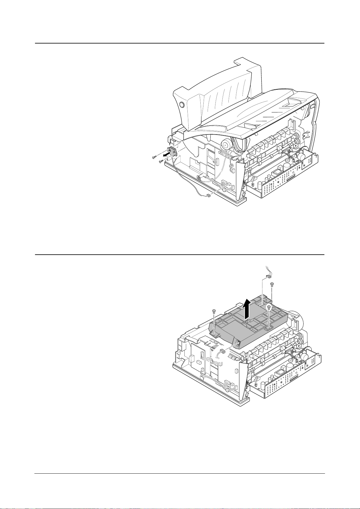
1. Before you remove the assembly, you should
remove:
– Rear cover (see page 3-3)
– Right side cover (see page 3-4)
– LIU board (see page 3-11)
2. Remove two screws, and unplug one connector from
the main board, then remove the socket contact
ass’y.
3-14 Socket Contact Assembly
1. Before you remove the LSU, you should remove:
– Rear cover (see page 3-3)
– Left/Right side covers (see page 3-3, 3-4)
– Top assembly (see page 3-8 )
2. Remove three screws, unplug two connectors, then
remove the LSU.
3-15 LSU
Disassembly and Reassembly
3-13
Samsung Electronics
3-16 Motor Assembly and Fan
1. Before you remove the motor assembly, you should
remove:
– Rear cover (see page 3-3)
– Left/Right side covers (see page 3-3, 3-4)
– Top assembly (see page 3-8)
2. Remove two screws securing the fan.
3. Remove five screws, unplug two connectors, then
remove the motor assembly.
4. Remove a screw securing the fan and remove the
fan.
5. Remove three screws from the motor assembly.
6. Remove two screws from the motor bracket and
remove the motor.
Disassembly and Reassembly
3-14
Samsung Electronics
1. Before you remove the fuser, you should remove:
– Rear cover (see page 3-3)
2. Remove the exit actuator and unplug two connectors.
3. Remove four screws, then remove the fuser.
3-17 Fuser
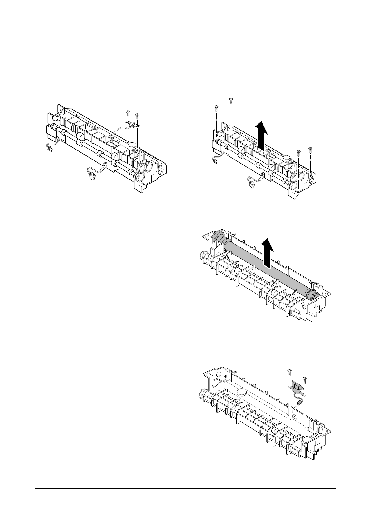
Thermostat on the Fuser
Remove two screws securing the thermostat and take it
out.
Thermistor on the Fuser
1. Remove four screws and remove the upper cover.
2. Remove the heat roller.
3. Remove two screws securing the thermistor, then
take it out.
Disassembly and Reassembly
3-15
Samsung Electronics
Disassembly and Reassembly
3-16
Samsung Electronics
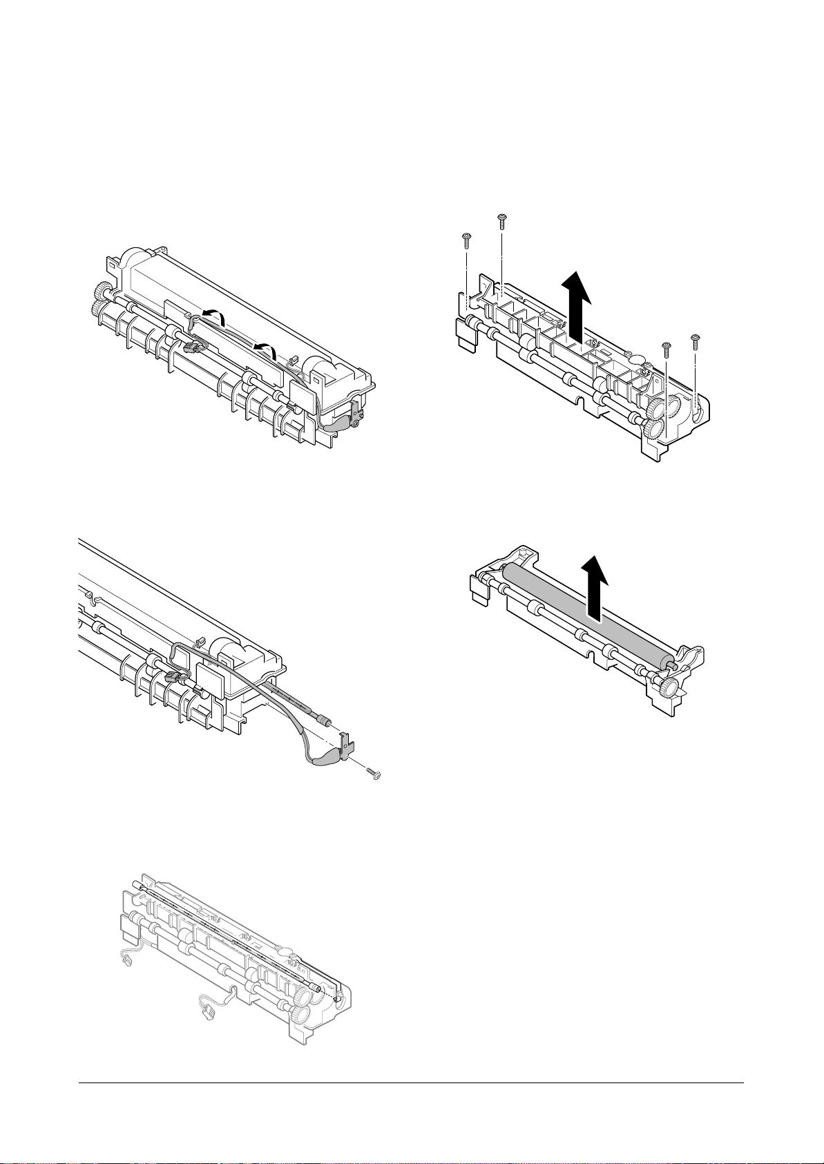
Halogen Lamp on the Fuser
1. Release the connector cable from its recessed channel.
2. Remove one screw and remove the halogen lamp.
Note: When you reassemble the lamp, make sure that
the halogen lamp is inserted in place.
Roller on the Fuser
1. Remove four screws and remove the upper cover.
2. Remove the roller.
Disassembly and Reassembly
3-17
Samsung Electronics
1. Before you remove the engine board, you should
remove:
– Rear cover (see page 3-3)
– Left/Right side covers (see page 3-3, 3-4)
– Top assembly (see page 3-8)
2. Remove four screws and remove the right and left
base brackets.
3. Remove two screws and remove the ICU ground.
4. Remove seven screws, and release the latch securing the PCU shield.
5. Unplug all connectors and remove PCU shield.
3-18 Engine Board and Others
Disassembly and Reassembly
3-18
Samsung Electronics
HV Terminals
Remove HV terminals. When you reassemble the terminals, make sure that the terminals are inserted in place.
Transfer Guide
Remove five screws and remove the transfer guide.
SCF Connector
Remove two screws and remove the connector.
Cover Open Sensor
Remove the spring and remove the sensor.
 Loading...