

Page 1
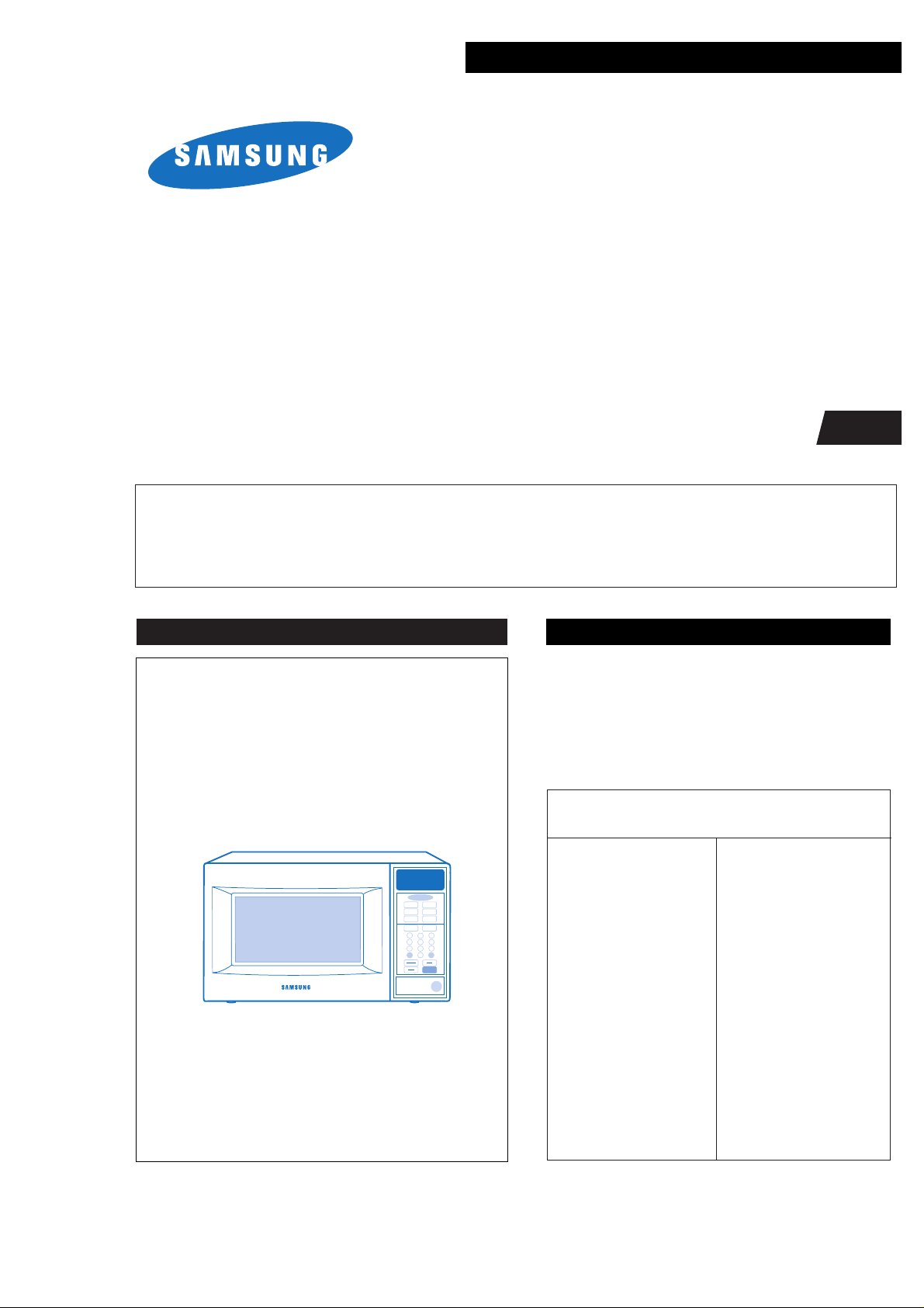
MICROWAVE OVEN
MR5483G / MR5484W
SERVICE
Manual
Supplement
MICROWAVE OVEN CONTENTS
Auto
Defrost
Auto
Reheat
Pause
Cancel
Start
Clock
Auto Start
Hold
Timer
One Minute +
Popcorn
Diet Cook
Potato
Frozen
Dinner
Fresh
Vegetable
Frozen
Breakfast
1
2
3
4
5
6
7
8
9
0
More/LessPower Level
1. Precaution
2. Control Panel
3. Exploded View & Parts List
4. P.C.B Diagram
5. Schematic Diagrams
SEA
THIS SUPPLEMENT CONTAINS EXPLODED VIEW AND PARTS LIST FOR MODEL MR5483G/MR5484W. FOR
MORE SERVICING INFORMATION, PLEASE CONSULT THE PREVIOUS SERVICE MANUAL FOR
MR5481G/MR5482W WHICH WAS DISTRIBUTED IN APRIL 1998.
Specifications
TIMER 99 MINUTES 99 SECONDS
POWER SOURCE 120V/60Hz, AC
POWER CONSUMPTION MICROWAVE : 1,300W
OUTPUT POWER 90W/900W
(IEC-705 TEST PROCEDURE)
OPERATING FREQUENCY 2,450MHz
MAGNETRON OM75PH(31)ESS
COOLING METHOD COOLING FAN MOTOR
OUTSIDE DIMENSIONS 20
11/32
(W) x 11
11/32
(H) x 14
5/8
(D)
Page 2

Samsung Electronics
(a) Do not operate or allow the oven to be
operated with the door open.
(b) Make the following safety checks on
all ovens to be serviced before activating
the magnetron or other microwave
source, and make repairs as necessary:
(1) Interlock operation,
(2) proper door closing,
(3) seal and sealing surfaces (arcing,
wear, and other damage),
(4) damage to or loosening of hinges
and latches,
(5) evidence of dropping or abuse.
(c) Before turning on microwave power
for any service test or inspection within
the microwave generating
compartments, check the magnetron,
wave guide or transmission line, and
cavity for proper alignment, integrity,
and connections.
(d) Any defective or misadjusted
components in the interlock, monitor,
door seal, and microwave generation
and transmission systems shall be
repaired, replaced, or adjusted by
procedures described in this manual
before the oven is released to the owner.
(e) A Microwave leakage check to verify
compliance with the Federal
performance standard should be
performed on each oven prior to release
to the owner.
PRECAUTIONS TO BE OBSERVED BEFORE AND DURING
SERVICING TO A VOID POSSIBLE EXPOSURE TO EXCESSIVE
MICROWAVE ENERGY
Page 3

1. Precaution
1-1 Safety precautions ( )
Samsung Electronics 1-1
1. All repairs should be done in accordance
with the procedures described in this
manual. This product complies with
Federal Performance Standard 21 CFR
Subchapter J (DHHS).
2. Microwave emission check should be
performed to prior to servicing if the oven is
operative.
3. If the oven operates with the door open :
Instruct the user not to operate the oven and
contact the manufacturer and the center for
devices and radiological health immediatly.
4. Notify the Central Service Center if the
microwave leakage exceeds 5 mW/cm
2
5. Check all grounds.
6. Do not power the MWO from a "2-prong"
AC cord. Be sure that all of the built-in
protective devices are replaced. Restore any
missing protective shields.
7. When reinstalling the chassis and its
assemblies, be sure to restore all protective
devices, including: nonmetallic control
knobs and compartment covers.
8. Make sure that there are no cabinet openings
through which people--particularly
children--might insert objects and contact
dangerous voltages. Examples: Lamp hole,
ventilation slots.
9. Inform the manufacturer of any oven found
to have emmission in excess of 5 mW/cm2,
Make repairs to bring the unit into
compliance at no cost to owner and try to
determine cause.
Instruct owner not to use oven until it has
been brought into compliance.
CENTRAL SERVICE CENTER
10. Service technicians should remove their
watches while repairing an MWO.
11. To avoid any possible radiation hazard,
replace parts in accordance with the wiring
diagram. Also, use only the exact
replacements for the following parts:
Primary and secondary interlock switches,
interlock monitor switch.
12. If the fuse is blown by the Interlock Monitor
Switch: Replace all of the following at the
same time: Primary and secondary switches,
as well as the Interlock Monitor Switch. The
correct adjustment of these switches is
described elsewhere in this manual. Make
sure that the fuse has the correct rating for
the particular model being repaired.
13. Design Alteration Warning:
Use exact replacement parts only, i.e., only
those that are specified in the drawings
and parts lists of this manual. This is
especially important for the Interlock
switches, described above. Never alter or
add to the mechanical or electrical design
of the MWO. Any design changes or
additions will void the manufacturer's
warranty.10.Always unplug the unit's AC
power cord from the AC power source
before attempting to remove or reinstall
any component or assembly.
14. Never defeat any of the B+ voltage
interlocks. Do not apply AC power to the
unit (or any of its assemblies) unless all
solid-state heat sinks are correctly installed.
15. Some semiconductor ("solid state") devices
are easily damaged by static electricity. Such
components are called Electrostatically
Sensitive Devices (ESDs). Examples include
integrated circuits and field-effect
transistors.
Immediately before handling any
semiconductor components or assemblies,
drain the electrostatic charge from your
body by touching a known earth ground.
16. Always connect a test instrument's ground
lead to the instrument chassis ground before
connecting the positive lead; always remove
the instrument's ground lead last.
Follow these special safety precautions. Although the microwave oven is completely safe during ordinary
use, repair work can be extremely hazardous due to possible exposure to microwave radiation, as well as
potentially lethal high voltages and currents.
Page 4
17. When checking the continuity of the witches
or transformer, always make sure that the
power is OFF, and one of the lead wires is
disconnected.
18. Components that are critical for safety are
indicated in the circuit diagram by
shading, or .
19. Use replacement components that have the
same ratings, especially for flame resistance
and dielectric strength specifications. A
replacement part that does not have the
same safety characteristics as the original
might create shock, fire or other hazards.
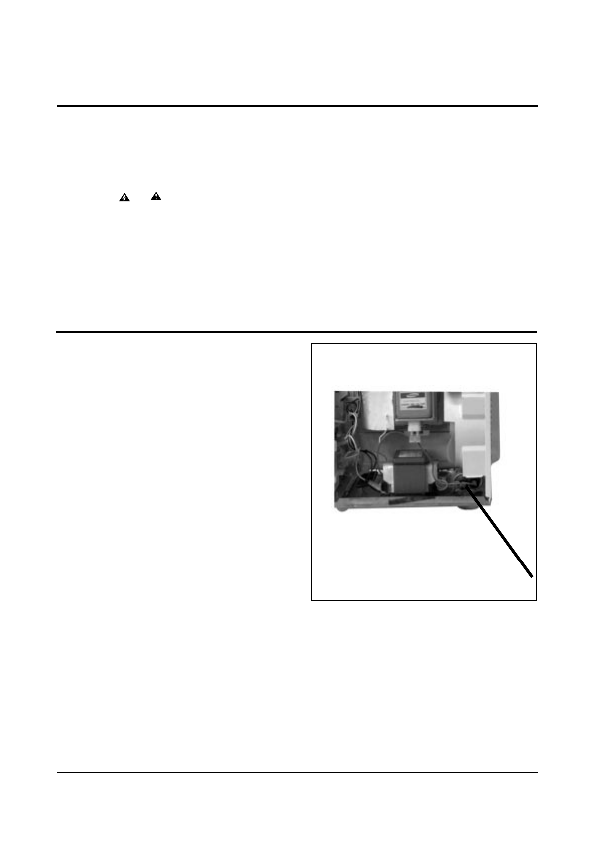
1. High Voltage Warning
Do not attempt to measure any of the high
voltages--this includes the filament voltage
of the magnetron. High voltage is present
during any cook cycle.
Before touching any components or wiring,
always unplug the oven and discharge the
high voltage capacitor (See Figure 1-1)
2. The high-voltage capacitor remains charged
about 30 seconds after disconnection. Short
the negative terminal of the high-voltage
capacitor to the oven chassis. (Use a
screwdriver.)
3. High voltage is maintained within specified
limits by close-tolerance, safety-related
components and adjustments. If the high
voltage exceeds the specified limits, check
each of the special components.
1-2
Pretaution
Samsung Electronics
1-2 Special Servicing Precautions (Continued)
1-3 Special High Voltage Precautions
Fig. 1-1. Discharging the High Voltage Capacitor
Page 5

2. Control Panel
8
6
5
0
A
1
9
2
3
4
7
1. One Minute + Button
2. Auto Defrost Button
3. Power Level Selection Button
4. Clock/Auto Start Button
5. Hold/Timer Button
6. More/Less Button
7. Pause Canel Button
8. Start Button
9. Instant Cook Buttons
10. Auto Reheat Button
11.Number Key Buttons
Auto
Defrost
Auto
Reheat
Pause
Cancel
Start
Clock
Auto Start
Hold
Timer
One Minute +
Popcorn
Diet Cook
Potato
Fresh
Vegetable
Frozen
Breakfast
Frozen
Dinner
1
2
3
4
5
6
7
8
9
0
More/LessPower Level
MR6472W
Samsung Electronics 2-1
Page 6

3. Exploded Views and Parts List
3-1 Exploded Views
M1
M2
M29
M21
M22
M23
C1
C2
C3
C4
C5
C6
M24
D1
D2
D3
D5
D8
D6
M25
M26
M11
M13
M14
M15
M12
M16
M17
M18
M19
M32
M20
M3
M4
M5
M6
M7
M8
M9
M10
B1
B2
B4
B3
I 1
I 3
M27
D4
D8
D7
M28
M31
M30
I 2
I 4
C7
3-1 Samsung Electronics
Page 7

3-2 Main Parts List
Samsung Electronics 3-2
Exploded Views and Parts List
Ref. No. Parts No. Description/Specification Q'ty Remarks
M 1 DE70-30001W PANEL-OUTER;V/STEEL T0.5+T0.2 W360 L1128 1 MR5483G
M 1 DE70-30001U PANEL-OUTER;SECC T0.6 W360 L1128 WHT MR548 1 MR5484W
M 2 DE91-40100A ASSY NOISE FILTER;SN-U15A 250V 15A SECA 1
M 3 DE63-90192A CUSHION-GUIDE;PUT-FOAN T35 W20 L325 BLK MR54 1
M 4 DE31-10156B MOTOR-FAN;SMF-557UC 120/60 2600 MW5574W 1
M 5 DE39-40594A WIRE HARNESS-A;120V60HZ MR6471G/MR5471G R/V 1
M 6 DE47-20009A THERMOSTAT;CS-7SA(160/60)187Y 250V7.5A 1 1
M 7 DE03-30035A MAGNETRON;OM75PH(31)ESS 1
M 8 4713-001012 LAMP-INCANDESCENT;130V,-,40W,ORG,B/L,-,2 1
M 9 DE71-60016A COVER-AIR;PP 2 WHT M945/MB45 1
M 10 DE93-20001B ASSY BODY LATCH;MW5371G 2ND-W1 R/V 1
M 11 DE66-90013A LEVER-DOOR;POM(F20-01) NTR MW5630T 1
M 12 DE26-10134A TRANS-H.V;SHV-5574UC1 120V 2160V/3.35V 1
M 13 2501-001011 C-OIL;910nF,2100V,BK,54x35x75,20mm 1
M 14 DE61-50106A BRACKET-HVC;SECC T0.8 W31 L125.8 1
M 15 DE91-70063A ASSY-H.V.D;V2M6 PI9.0 0.05MT 1
M 16 DE74-20015B TRAY-COOKING;GLASS T6.0 PI318 1050G MW56 1
M 17 DE92-90189D ASSY-GUIDE ROLLER;D19 STD 1
M 18 DE67-60026C COUPLER;PTFE 12G WHT MB245 1
M 19 DE61-40065A FOOT;PP BLK T2x22x17mm 2
M 20 DE80-10001C BASE-PLATE;SGCC T0.8 W345 L565 MR5481G 1
M 21 DE31-10154A MOTOR-DRIVE;M2HJ49ZR02,ST-16 21V 5/6 1
M 22 DE71-60011A COVER-MGT;PP T2.0 WHT M745 1
M 23 ASSY CONTROL-BOX;120V60Hz MR5483G/XAA D/GRY 1 MR5483G
M 23 ASSY CONTROL-BOX;120V60Hz MR5484W/XAA WHT 1 MR5484W
M 24 ASSY DOOR;TOUCH GRAY MW5471G 1 MR5483G
M 24 ASSY DOOR;TOUCH WHT MW5470W 800W 1 MR5484W
M 25 DE61-80003A HINGE-LOWER;SCP1 T2.3 26 77 ZPC3 WHT CHR 1
M 26 DE61-80002A HINGE-UPPER;SCP1 T2.3 26 77 ZPC3 WHT CHR 1
M 27 DE39-20037G ASSY POWER CORD;KKP-30B 120V60HZ 1150 GRY 1
M 28 DE47-20173A THERMOSTAT;PW-2N(90/60)30 187Y 250V7.5A 1
M 29 DE63-90035G CUSHION-RUBBER;DFA20 T2 W190 L100 BLK 1
M 30 DE61-50490A BRACKET-TCO;SECC1 T0.6 34 58 1
M 31 DE91-70101C ASSY-THERMOSTAT;MW5574W 160/60 187-HORIZ 1
M 32 DE60-60025A PIN-FOOT;PP-JI350 BLK 1
: Option Parts
: Warning
:Electrostatically Sensitive Devices
Page 8

Samsung Electronics3-3
Exploded Views and Parts List
Ref. No. Parts No. Description/Specification Q'ty Remarks
D 1 DE64-40241B DOOR-A;ABS WHT (HRO370) GRY MW5471G 1 MR5483G
D 1 DE64-40241A DOOR-A;ABS WHT M841 1 MR5484W
D 2 DE64-40006A DOOR-KEY;POM(TC3005) T2.0 12GR BLK CE945G 1 MR5483G
D 2 DE64-40006B DOOR-KEY;POM(TC3005) T2 12GR WHT MW5574 1 MR5484W
D 3 DE61-70032A SPRING-KEY;ES HSWR PI0.6 D5.4 L25 MW8640 1
D 4 DE67-20157B SCREEN-DOOR;PC T0.5 181.5 331.5 GRY MW5471G 1 MR5483G
D 4 DE67-20157A SCREEN-DOOR;PC T0.5 188 331 PURE-WHT NEWGU 1 MR5484W
D 5 DE92-50127G ASSY DOOR-E;WELDING T0.8 1
D 6 DE64-40012A DOOR-C;RESIN-PP(TB53) T2.0 CE945GF BLACK 1
D 7 DE01-00002B FILM-DOOR;PC T0.15 275 175 MW5574W 1
D 8 DE92-40207B ASSY DOOR-SUB;MW5575G BLK DOOR-FILM 1 MR5483G
D 8 DE92-40207A ASSY DOOR-SUB;MW5574W WHT DOOR-FILM 1 MR5484W
Ref. No. Parts No. Description/Specification Q'ty Remarks
C 1 DE66-20010B BUTTON-PUSH;ABS D-GRY MW4371G 1 MR5483G
C 1 DE66-20010A BUTTON-PUSH;ABS (VH-080) WHT 17.6G MW4370W 1 MR5484W
C 2 DE61-70076A SPRING-BUTTON;HSWR PI0.6 1
C 3 DE34-10217Y SWITCH-MEMBRANE;PET W91.5 L174.5 MR5483G 120V 1 MR5483G
C 3 DE34-10217Z SWITCH-MEMBRANE;PET W91.5 L174.5 MR5484W 120V 1 MR5484W
C 4 DE72-70161B CONTROL-PANEL;ABS(HR0370U) GRY MW5471G 1 MR5483G
C 4 DE72-70161A CONTROL-PANEL;ABS(VH-0800) PURE-WHT MW5470W 1 MR5484W
C 5 DE67-40003A WINDOW-DISPLAY;ACRYL T2.3 W36.8 L91.8 SM 1
C 6 DE91-10368A ASSY P.C.B-MAIN;120V/60HZ NS V.F.D N/HEL 1
C 7 DE93-30402F ASSY CONTROL-PANEL;MR5481G WINDOW SHEET 1 MR5483G
C 7 DE93-30402J ASSY CONTROL-PANEL;M94B/SBW 1 MR5484W
3-4 Control Parts List
3-3 Door Parts List
7-5 Body Latch Parts List
Ref. No. Parts No. Description/Specification Q'ty Remarks
B 1 DE66-40001A LATCH-BODY;POM(F20-02) 40GR NTR 1
B 2 3405-000178 SWITCH-MICRO;VP-533A-OF-PS(T85) 250V,15A 3
B 3 3405-000175 SWITCH-MICRO;VP-531A-OF(T85) 250V,15A,20 1
B 4 DE66-90001A LEVER-SWITCH;P.O.M(F20-02) 2 6 NTR 2ND-W 1
Page 9

Samsung Electronics 3-4
Parts No. Description / Specification Q'ty Remarks
DE60-10082A SCREW-A;M4 L12 2S TOOTHED 2 BASE
DE60-10088A SCREW-TAP PH;PH M3 L8 FEFZY PLAIN 2 PCB
DE60-10082A SCREW-A;M4 L12 2S TOOTHED 2 B-LATC
DE60-10082A SCREW-A;M4 L12 2S TOOTHED 2 C-PANE
DE60-10082A SCREW-A;M4 L12 2S TOOTHED 5 O-PANEL
DE60-10082A SCREW-A;M4 L12 2S TOOTHED 1 P/EART
DE60-10080A SCREW-WASHER;M5 L12 2S 4 HVT
DE60-10080A SCREW-WASHER;M5 L12 2S 4 MGT
DE60-10033A SCREW-TH;TH + M4 L10 MSWR10 FEFZY 2 HI-LOW
DE60-10082A SCREW-A;M4 L12 2S TOOTHED 2 C-BLOW
DE60-10033A SCREW-TH;TH + M4 L10 MSWR10 FEFZY 2 HI-UPP
DE60-10045A SCREW-TAP PH;PH M3 L6 FEFZY 2 MGT-TC
DE60-10082A SCREW-A;M4 L12 2S TOOTHED 1 MEM-PN
DE60-10098A SCREW-ASSY TAPTITE;PH TC M4X8 SWRCH18A Z 1 CV-TCO
DE60-10098A SCREW-ASSY TAPTITE;PH TC M4X8 SWRCH18A Z 2 M/GEAR
DE60-10113A SCREW-TAP PH;2S-4X12 FE ZPC3 1 FUSE-H
DE60-10188A SCREW-ASSY TAP;2S-4X8 MSW3ZPC YEL WS 1 B/HVC
3-6 Standard Parts List
Exploded Views and Parts List
3-7 Installation Parts List
Ref. No. Parts No. Description/Specification Q'ty Remarks
I 1 DE70-40311A PLATE-BOTTOM;SGCC T0.6 W253 L264.5 MR5481 1
I 2 DE72-50092A DUCT-AIR;SGCC T0.6 W150 L212 MR5481G 1
I 3 TRIMMER-LOWER 1
I 4 TRIMMER-UPPER 1
Page 10

Samsung Electronics4-1
4. P.C.B Diagrams
4-1 P.C.B Diagrams
3. DOOR IS OPENED.
4. OPTION KEY : II ( 9 & 13SHORTED)
Page 11

4-2Samsung Electronics
P.C.B Diagrams
Parts No. Description / Specification Q'ty Remarks
0401-001002 DIODE-SWITCHING;1N4148M,100V,200mA,500mW 16 D05~20
0402-000559 DIODE-RECTIFIER;D4G,400V,1A,T-1 3 D01,02,04
0501-000283 TR-SMALL SIGNAL;KSA539-Y,PNP,400mW,TO-92 1 Q08
0504-001014 TR-DIGITAL;KSR1005,NPN,300mW,4.7K-10K,TO 5 Q01,06,07,09,10
0504-001015 TR-DIGITAL;KSR2005,PNP,300mW,4.7K-10K,TO 4 Q02~05
1405-000129 VARISTOR;INR14D271K 270V,4500A 17X12MM,T 1 ZNR1
2001-000037 R-CARBON(S);330ohm,5%,1/2W,AA,TP,2.4x6.4 2 R03~04
2001-000273 R-CARBON;100Kohm,5%,1/8W,AA,TP,1.8x3.2m 2 R17,21
2001-000290 R-CARBON;10Kohm,5%,1/8W,AA,TP,1.8x3.2mm 5 R07,10,14,15,19
2001-000429 R-CARBON;1Kohm,5%,1/8W,AA,TP,1.8x3.2mm 4 R05,06,11,12
2001-000515 R-CARBON;220ohm,5%,1/8W,AA,TP,1.8x3.2mm 1 R09
2001-000577 R-CARBON;2Kohm,5%,1/8W,AA,TP,1.8x3.2mm 1 R13
2001-000613 R-CARBON;3.9Kohm,5%,1/8W,AA,TP,1.8x3.2m 8 R16,18,20,26~30
2001-000780 R-CARBON;470ohm,5%,1/8W,AA,TP,1.8x3.2mm 2 R01,02
2001-000786 R-CARBON;47Kohm,5%,1/8W,AA,TP,1.8x3.2mm 20 R31~50
2001-000904 R-CARBON;620ohm,5%,1/8W,AA,TP,1.8x3.2mm 1 R08
2011-000582 R-NETWORK;47Kohm,5%,1/8W,A,SIP,9P,TP 1 AR01
2202-000121 C-CERAMIC,MLC-AXIAL;UP050B101KBB 100PF,1 1 C09
2202-000127 C-CERAMIC,MLC-AXIAL;TP050F103ZB 10NF,+80 1 C10
2202-000780 C-CERAMIC,MLC-AXIAL;UP050F104Z 100NF,+80 4 C05~07,11
2401-000247 C-AL;1SA1ANB107MAN 100UF,20%,10V,GP 6.3X 1 C14
2401-000466 C-AL;CESSM1V100M0507 10UF,20%,35V,GP 5X7 1 C08
2401-000914 C-AL;CESSL1C220M0511AA 22UF,20%,16V,GP 5 1 C03
2401-001412 C-AL;1SG1VFB477MAN 470UF,20%,35V,GP 10X1 2 C01,02
2802-000161 RESONATOR-CERAMIC;CST4.00MGW-TF01-3/CN 4 1 X-TAL
3501-001014 RELAY-POWER;OM1F-S-124LM 24V,21.8MA,17A 1 RY02
3501-001016 RELAY-MINIATURE;JV24-KT 24V,12.5MA,5A 1F 1 RY01
3708-000529 CONNECTOR-FPC/FC/PIC;FCZ254-14SL,BLK 14P 1 CON05
3711-000240 CONNECTOR-HEADER;1WALL,4P,1R,3.96mm,STRA 1 CON01
3711-000881 CONNECTOR-HEADER;SMW250-03,WHT BOX,3P,1R 1 CON04
A4106-0154 DIODE-ZENER;TZP5.1B 5.1/5.7V 40MA T 1W 3 ZD01~03
DE07-10035A V.F.DISPLAY;SVM-07SS10 SEA 1 VFD1
DE09-30491A IC-MCU;MB89143AP-168 8K DIP 64PIN 1 IC01
DE13-20009A IC;KA7533 DIP 1 IC02
DE26-20144A TRANS-L.V;DN-5574W,CE-5574W 120V 60HZ AC 1 LVT1
DE30-20016A BUZZER;CBE2220BA STICK 1 BUZ1
DE39-60001A WIRE-SO COPPER;PI0.6 SN T 52MM 25 J01~25
DE60-60012A PIN-EYELET;ID2.1 OD2.5 L3.0 SN BSP T0.25 8
DE61-90164A HOLDER-DIGITRON;NYLON#66 T1.8 BLK MW4370 1*
4-2 P.C.B Parts List
Page 12

5-1
Samsung Electronics
5. Schematic Diagrams
VARISTOR
L.V.TRANS
LAMP
MAIN
RELAY
MAIN
RELAY
POWER
RELAY
POWER
RELAY
SECONDARY S/W
PRIMARY S/W
CAVITY
TCO
FAN
MOTOR
DRIVE/MOTOR
MONITOR
SWITCH
H. V. TRANS
H. V. CAPACITOR
H. V. DIODE
0V
F FA
MAGNETRON
POWER CORD
AC 120V/60Hz
(N)
(L)
BLK
BLK
BLU
BLK
BLKBLKBLK
BLK
BLK
YEL
YEL
WHT
WHT
WHT
WHT
WHT
WHT
WHT
1. INPUT : 120V 60HZ
2. DOOR : OPEN
3. LAMP : ON
4. : P.C.B PATTERN
5. : P.C.B IN/OUT POINT
WHT : WHITE
BLK : BLACK
YEL : YELLOW
BLU : BLUE
ORG : ORANGE
GRN : GREEN
RED : RED
MGT
TCO
COM
NC
120V
120V
130V
40W
21V
0V
NO
L
FM DM
ASSY CHOKE P.C.B
FUSE
GRN
GRN
ORG
ORG
G
GND
GND
C1
C3
C2
0.9mH
500K
2200pF2200pF
BLK BLK
BLK
WHT
BLU
ORG
NO
COM
ORG
NO
COM
BLK
NC
COM
DOOR
SENSING
SWITCH
DOOR
SENSING S/W
INTERLOCK
MONITOR
SWITCH
PRIMARY
INTERLOCK
SWITCH
WHT WHT
WHT
NO
COM
SECONDARY
INTERLOCK
SWITCH
(CON1)
ASS'Y P. C. B
WARNING
POWER MUST BE DISCONNECTED
BEFORE SERVICING THIS APPLIANCE
CONDITION
NOTE : FOR SERVICE REPLACEMENT USE 16 GA 105˚ C
THERMOPLASTIC COVERED WIRE EXCEPT
FOR HIGH VOLTAGE LEADS OR AS NOTED
ON SPECIAL LEADS.
RED
RED
RED
ORG
WHT
BLK
MAGNETRON
HIGH VOLTAGE
DIODE
TO CHASSIS
FA F
HIGH VOLTAGE
TRANSFORMER
HIGH VOLTAGE CAPACITOR
BLK
 Loading...