

SAMSUNG Ml85 Service Manual

2-4 Recommended Test Equipment
Samsung recommends the following equipment when servicing the Laser Printer.
Digital Multimeter A digital multimeter with attached LED or LCD 4-digit Panel.
Oscilloscope A digitizing oscilloscope which can measure more than
High Voltage probe
DCU (Diagnostic Control Unit) DCU can be supplied from Samsung which can easily shows the engine’s
A high voltage probe which can measure about less than
Error status
Table 2-4-l Equipment List
QUIDCK
REFERANCE
+
0
STATUS
+
0
MAGNOSTIC
DIAGNOSTIC CONTROL
5PPM
LASER BEAM PRINTER
+
cl
ON OFF
UNIC
1OOMHz
1OKV
UP
DOWN SHIFT
Figure 241 DCU
28
ENTER
STOP
2-5 DCU Control
2-5-l DCU Setup
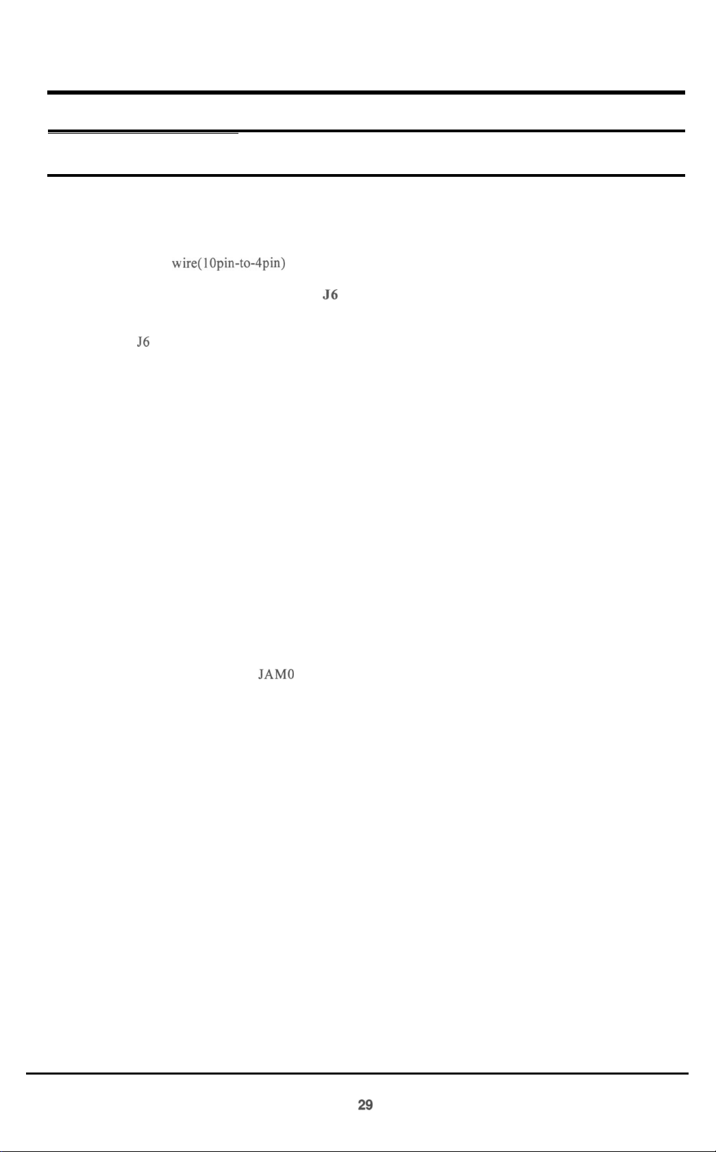
The DCU is used to diagnose Printer malfunctions.
The DCU harness wire(lOpin-todpin) is connected to the Printer engine via:
1) Engine Board connector, CN2 (4pins)
2) (Video) Controller Board connector, 56 (4pins)
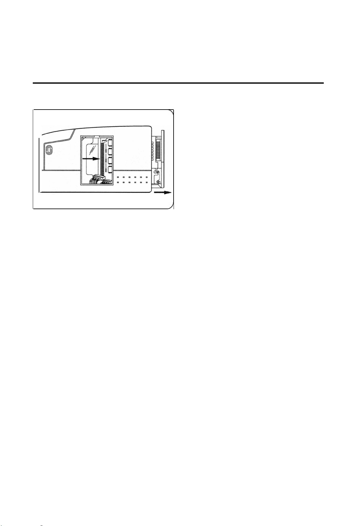
Open the Printer’s side cover(=SIMM Cover) and remove the shield cover and connect the DCU
to connector 56 on the Controller Board.
2-5-2 DCU Error messages (LED Display)
If an error occurs, connect the DCU to the Printer. DCU messages will indicates malfunctioning
areas of the machine.
(Consult Service Manual for detailed troubleshooting information)
Display
60
62
64
68
70
71
72
73
95
Error messages
OPEN FUSER ERROR
LOW HEAT ERROR
COVER OPEN ERROR
OVERHEAT ERROR
NO PAPER OR CASSETTE
PAPER
JAM1 (REGISTER SENSOR TO EXIT SENSOR)
JAM2 (EXIT SENSOR TO FUSER)
LSU NOT READY
JAM0
(CASSETTE PICK-UP TO REGISTER SENSOR)
29

2-5-3 DCU diagnostic messages (LED display)
After receiving an error message, use the DCU to locate malfunction unit.
Displav
0
1
2
3
4
5
6
I
8
9
10
11
12
13
14
Error messaee
MAIN MOTOR OPERATING SYSTEM
MAIN HIGH VOLTAGE ON (- 14KV)
TRANSFER HIGH VOLTAGE
THV
(+)
REFERENCE VOLTAGE
DEVSUPPLY HIGH VOLTAGE ON
LSU OPERATING TEST
PICKUP CLUTCH ON
PAPER EMPTY SENSOR TEST
FEED & EXIT SENSOR TEST
COVER OPEN SENSOR TEST
FUSER TEST
HOT BURN TEST
CLEAN (MESSAGE) PRINT
THV TRIGGER & THV ON DUTY
THV PLUS DUTY
(-)
ON
(+9OOV)
2-5-4 DCU Diagnostic Mode
1) Connect DCU to Controller or Engine Board
2) To apply power, simultaneously press tand hold ‘DOWN’, ‘SHIFT’, and ‘STOP’ keys. 78 will display
3) After 2-3 seconds, release the keys. 00 will display
4) Press ‘UP’ or ‘SHIFT+DOWN’ keys until the desired number is displayed in the DCU display.
5) Press ‘ENTER’ to begin operating.
30

6) Example
Select numbers 13 and 14 to adjust the electrophotography trigger voltage.
1: Turn power on by simultaneously pressing ‘DOWN’, ‘SHIFT’, and ‘STOP’ for 2-3 seconds.
2: Press
‘SHIFT+DOWN’
until diagnostic cocde
#14
is displayed.
4: Press ‘SHIFT’ and ‘STOP’ to exit routine.
5: Press ‘SHIFT’ and ‘DOWN’ to display diagnostic code
#13.
6: Display will antemate between electronc photography trigger voltage and On duty voltage.
7: To end operation, press ‘SHIFT’ and ‘STOP’ keys.
7) DCU Error Message
a) Error messgae
Error message
Error message
‘60’,
‘THERMISTOR OPEN ERROR’
‘62’,
‘LOW TEMPERAURE ERROR’
‘68’,
‘OVERHEAT ERROR’
Action:
1) Measure Fuser’s Thermistor resistance
Normal Thermistor resistance is 2-3 ohms (1
lOV),
6-10 ohms (220V)
2) Confirm Fuser Lamp operation
3) Measure Engine Board resistances at QlOl (Triac Thyrister)
4) Replace Engine Board Q 10 1
5) Replace Engine Board Q3 (KSC 1008-Y)
6) Replace Engine Board PC 15 1 (Triac Photo Coupler)
b) Error message
‘70’,
‘PAPER EMPTY’
Action:
1) Check for paper in cassete tray
2) Replace 0P2 Sensor (Photo Interrupter)
3) Confirm Feed Clutch operation (mode ‘06’)
4) Replace Feed Clutch or Engine Board’s 44 (KSC 1008-Y)
c) Error message ‘7
1’)
‘PAPER JAM- 1’
Action:
1) Check for paper in cassette tray
2) Check for Pick-up unit wear
3) Replace OP 1 sensor (Photo Intermpter)
31

d) Error message
Error message
‘72’,
‘PAPER JAM-2’
‘73’,
‘PAPER JAM-3’
Action:
1) Confirm that normal paper is being used
2) Check for Paper Jam in Fuser
3) Replace sensor ‘SW 1’ on Engine Board
4) Check for Fuser Roller contamination
8) Error message
‘95’,
‘LSU READY ERROR’
a) Confirm normal readings at Engine Boards, QS
b) Replace LSU
(KSC1008-Y)
32

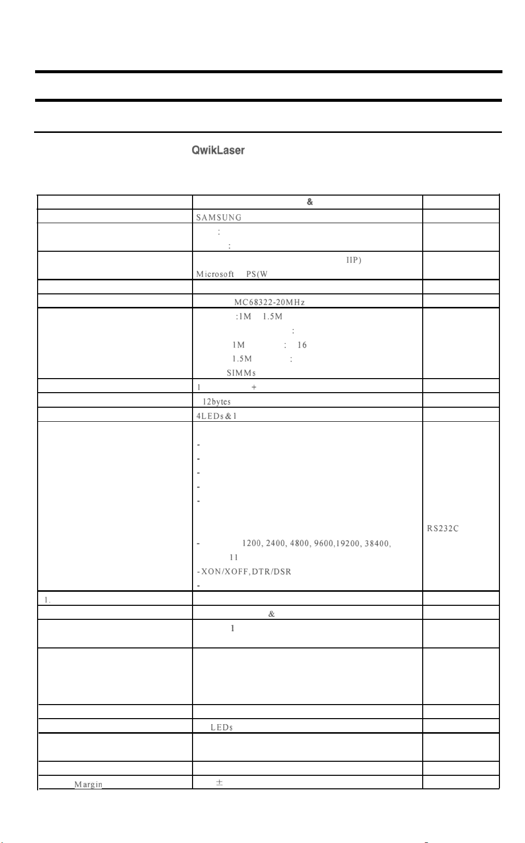
3. Product Information
3-1 Specifications
3-l -1 Engine(ML-80)
Specifications are correct at the time of printing. Product specifications are subject to change without notice.
I
1. Engme
3. Print Speed
Resolution
Source Of
Print Method
Feed Method
Feed Stde
Paper Handling (input)
I.
Paper Handling (output)
1 I
Feed
112.
Warm-up Time
113. Ftrst
114.
Print Time
Power
15. Power Consumption
Item
Ltght
Capactty
Rating
r
16.
Power Saving Consumption
r---
1 I7
Power Swatch
18.
Certification & Compliance
19.
Acoustic Standby
Noise
Operating
Specification & Description
VlL-80
Desktop Page Printer
I
ppm(page per minute)
A4 Size, 5% Character Pattern)
frue
600 X 600 dpi(dot per inch)
,aser
Diode (LSU: Laser Scanner
\Jon-impact
3assette & Manual
side
L
Size
0
0
Electrophotography
Loading
Standard : A4, Letter, Legal, B5, Executive
Envelope : manual feed only
Untt)
)I
0
Universal type
Length : 150 - 356 mm
Width:
k
Weight : For Cassette, 60 - 90
t
Recommended Paper
90-216mm
For Manual, 60 -
120
g/in’
g/m’
USA: X420, X4024, NEKOSA, BOISE CASCADE
EC: REFLEX, ADAGIO
Transparancies:
Label: AVERY 53XX series
:ace
Down :
Tace
Up : lsheet
3M (CG3300 or 3360)
150sheets
50-sheet Tray
!50-sheet Tray and one opttonal 250-sheet Drawer
3etween 25seconds
setween 25seconds
\C
100-I
2OV/220-240V (*
15%) 50Hz/60Hz (+ 3%)
‘eak: 720W
luring
Printing :
luring
Sleeping
,ess
than 28W during I hour at first
Vane
3E,
TUV, SEMKO, NEMKO, DEMKO, C-tick,
FCC, UL,
Less than 29dB
Less than 47dB
l50WH
(Average)
:
Max 1 SW
CSA, CDRH, CB,
MEEI
CClB
Remarks
Small Footprint
At Copy Mode
Left Adjust
ML-84/85G
ML-84/85G plus
ML-85, ML-85 plus
For EPA
Class B for EMC
33

item
3. Reliability
1.
Toner Supply
2. Expected Life Span
3. Operating Environment
4.
Storage Environment
5. Weight
5. External Dimension
7. Print Cartridge
8. Packing
MPBJ
MPBF
MTBF
Main Kit
Specification & Description
2,500 pages/75g Paper
30,000 pages
2,250 hours
(MTBF =
Print Cartridge
100,OOOsheets
Temperature : 10 - 30
Humidity : 30 - 80 %RH
Temperature : 0 - 35
Humidity : IO - 90 %RH
Net : Max 9.3kg
Gross : Max
ML-84/85G, QwikLaser 84/856
ML-85, QwikLaser 85
Ml-84
ML-85 plus
Life Span : 5,000 pages, 5% Pattern and 50% Duty
Developing : Non-magnetic Contact Developing
Charging : Conductive Roller Charging
Density Adjustment : 3steps (Light, Medium, Dark)
Toner Supply Method Exchanging The Developer
Toner Checking Sensor : None
Transfer System: Conductive Roller Transfer
Fusing System : Temperature & Pressure
Erasing Method: Light Using LED
Ozone Emission : Less than
Printer
Cassette
Developer Cartridge1 Piece
Guide Manual and Diskettes
Power Cord
7.5hours
10.5Kg
pIus/85G
X 20days X MPBF /Monthly Use)
“C
“C
360(W) X 367(D) X 176(H)
360(W) X 367(D) X 188(H)
plus
I
Set
1
Piece
1
Piece
360(W) X 375(D) X 176(H)
360(W) X 367(D) X 188(H)
O.IPPM
Remarks
Jam Rate
For machine
Normal:22 “C 65%
mm
mm’
mm’
mm’
Negative(-)
PWM Control
Quenching Lamp
33-l
3-l-2 ML-84, ML-84 plus or
Specifications are correct at the time of printing. Product specifications are subject to change without notice,
And ML-84 plus has the new front cover.
QwikLaser
84
Item
Interface Engine
Resolution
Emulation
Including the driver
Font
CPU
RAM MEMORY
ROM
EEPROM
Front Control Panel
0. Interface
Specification & Description
SAMSUNG ML-SO
WPS : 600 X 600 dpi
PCL4.5 : 300 X 300 dpi
PCL4.5 (Compatible with HP LaserJet IIP)
Mtcrosoft W
7 bitmaps
Motorola MC68322-20MHz
Standard : IM or
Optional SIMM Module
* These SIMMs are compatible with the Computer’s,
1
Mbyte (Font + Program)
5 12bytes
4LEDs
Bidirectional Parallel Standard
-
IEEE1284 COMPATIBLE MODE
-
IEEE1284 NIBBLE MODE
-
IEEE1284 BYTE MODE
-
IEEE1284 ECP WITHOUT RLE
-
IEEE1284 ECP WITH RLE
PS(W
indows Printing System)
1.5M
bytes
:
For IM Standard : 4, I6 Mbytes
For
1.5M
Standard : 4, 16 Mbytes
&
1
key
Remarks
NVRAM
Centronics
Use ECP cable
I. Copy Capacity
2. Interface Switching
3. Interface Time Out
4. Jam Recovery
5 AEP
6. Engine Interface Error
7. Status Monitor
8. PRS Buffer
9. Top Margin
Serial Interface Optional
-
300,600,
57600, I1 5200 bps
-
XON/XOFF, DTR/DSR Protocol
-
Robust XON for XON/XOFF
Enable up to 999
Automatic (Serial & Parallel)
1 step is I second from 20 seconds to 5 minutes.
(Zero is disable)
Jam 0, 1, 2 according to the Jam position
The recopy of Jam 0, 1 is default.
The recopy of Jam2 is optional.
(Don’t use Jam2 recovery under WPS status.)
Emulation switching according to Emulation code.
All LEDs blink when communication is error
Bidirectional Status Feedback
Animation for printing
755Kbytes
4.23 f 2.0 mm
1200,2400,4800,9600,
19200,38400,
33-2
RS232C
WPS only
PC L Pattern

3-l-3 ML-85, ML-85 plus or
Specifications are correct at the time of printing. Product specifications are subject to change without notice
And ML-85 plus has the new front cover.
QwikLaser
85
Item
Interface Engine
Resolution
Emulation
Including the driver
4
Font
5
CPU
RAM MEMORY
6
ROM
EEPROM
Front Control Panel
0. Interface
I
SAMSUNG ML-80
WPS : 600 X 600 dpi
PCL5e (Compatible with HP LaserJet
Microsoft WPS(W indows Printing System)
1
bitmap
45 scalable (35 intelligent, 10 truetype)
Motorola MC68322-20MHz
Standard : 2Mbytes
Option SIMM Module : 2, 4, 8, 16 Mbytes
* These SIMMs are compatible with the Computer’s,
2Mbyte (Font + Program)
5 12bytes
4LEDs &
Bidirectional Parallel Standard
-
IEEE1284 COMPATIBLE MODE
-
IEEE1284 NIBBLE MODE
-
IEEE1284 BYTE MODE
-
IEEE1284 ECP WITHOUT RLE
-
IEEE1284 ECP WITH RLE
Specification & Description
SP)
lkey
1
Remarks
NVRAM
Centronics
Use ECP cable
1.
Copy Capacity
2. Interface Switching
3. Interface Time Out
4. Jam Recovery
5. AEP
6. Engine Interface Error
7. Status Monitor
8. PRS Buffer
9. Top Margin
Serial Interface Optional
-
300, 600,
57600, 115200 bps
-
XON/XOFF, DTR/DSR Protocol
-
Robust XON for XON/XOFF
Enable up to 999
Automatic (Serial & Parallel)
1 step is 1 second from 20 seconds to 5 minutes.
(Zero is disable)
Jam 0, 1, 2 according to the Jam position
The recopy of Jam 0, 1 is default.
The recopy of Jam2 is optional.
(Don’t use Jam2 recovery under W PS status.)
Emulation switching according to Emulation code.
All LEDs blink when communication is error
Bidirectional Status Feedback
Animation for printing
755Kbytes
1
4.23 * 2.0 mm
1200,2400,4800,9600,
19200, 38400,
RS-232C
WPS only
1
PCL Pattern
33-3

3-l-4 ML-85G, ML-85G plus or QwikLaser 85G
Specifications are correct at the time of printing. Product specifications are subject to change without notice.
And ML-S% plus has the new front cover.
Item
1.
Interface Engine
2. Resolution
3 Emulation
Including the
4. Font
5. CPU
6. RAM MEMORY
7 ROM
8
EEPROM(=NVRAM)
9 Front Control Panel
IO. Interface
I I
Copy Capacity
12.
Jam Recovery
13.
Engine Interface Error
14. Status Monitor
115.
PRS Buffer
drover
Specification & Description
SAMSUNG ML-SO
WPS : 600 X 600 dpi
Computer 16Mbytes RAM : 300 X 300 dpi
PCL4
(Compatible with HP LaserJet II)
Microsoft WPS(Windows Printing System)
HP LaserJet II Internal fonts
None (ASIC dependent on host computer)
Standard :
None
ML-85G, ML-85G
QwikLaser 85G
ML-85G,
ML-85G
Bidirectional Parallel Standard
-
IEEE1284 COMPATIBLE MODE
-
IEEE1284 NIBBLE MODE
-
IEEE1284 BYTE MODE
-
IEEE1284 ECP WITHOUT RLE
-
IEEE
Serial Interface : None
Enable up to 999
Jam 0, I, 2 according to the Jam position
The recopy of Jam 0, I is default.
The recopy of Jam2 is optional.
(Don’t use Jam2 recovery under WPS status.)
All
Bidirectional Status Feedback
Animation for printing
755Kbvtes
O.SMbytes
plus
QwikLaser 85G
plus
1284
ECP WITH RLE
LEDs
blink when communication is error
None
X24COl
5
4
LEDs
LEDs
P
only
only
Remarks
S/W Driver
No option memory
POWER LED
READY LED ON
Centronics
Use ECP cable
WPS only
33-4
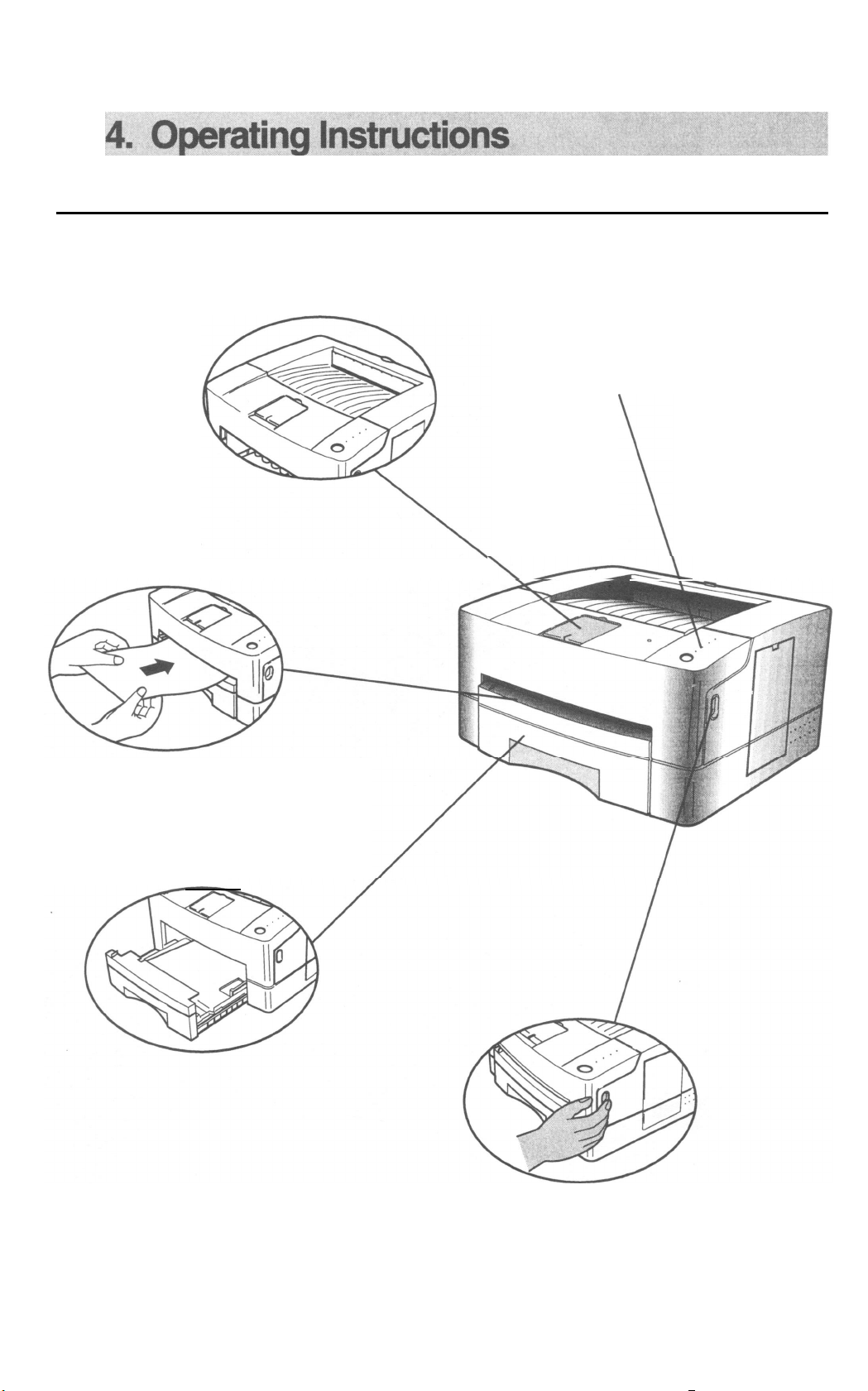
4-1. External Views and Functions
Face Down Tray
Control Panel
Each LED indicates printer status.
Manual Feeder
Cassette
\
\-
35
Cover Open Button

Parallel Connector
It connects
parallel port
Computer
Facu
up Tray
Open Face up Tray and it will
stacks one page.
Air Flow hole
Emits internal
thermal air
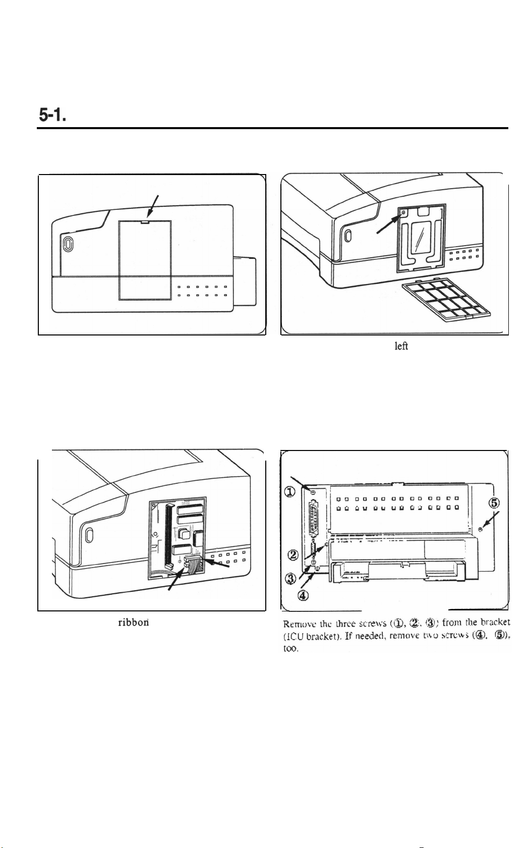
5. Disassembly
5-l.
Controller Disassembly
Remove the SIMM cover.
Push the tab down and pull the SIMM cover away from
the printer.
Remove the two
controller board.
ribboa
connectors on the video
Remove the screw in upper
panel, then remove the panel to expose the video
controller board.
left
comer of the metal
37
c
/
Pull the rear metal panel out and slowly slide the video
controller out of the LBP and put it on a flat surface.
38

5-2.
Cover Housing Disassembly
Remove the Drum unit, and place it in a place isolated from direct sunlight.
wire
panel
Locate and remove the two screws along the rear side
of the printer.
Turn the printer’s front to you then lift the door and
remove the two screws. If the printer has the Cleaning
roller, there should be a connection between OUT of
Cleaning board and IN of Cleaning roller.
From underneath the door, using your thumb, as shown,
pull the hook to the left and then pull out the cap wire
panel.
Remove the Panel PBA harness and locate it not to
prevent you from working.
39
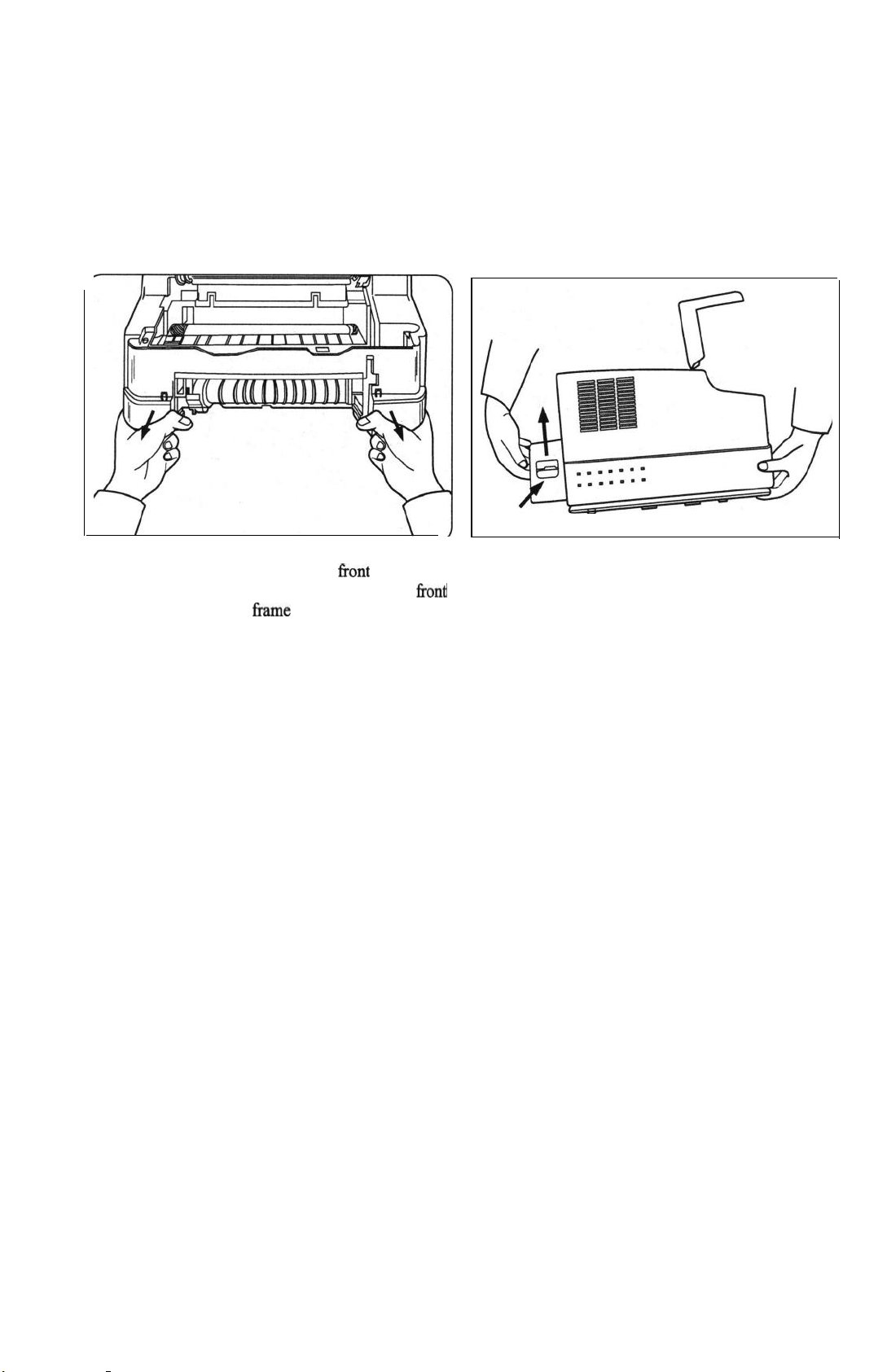
To remove the entire cabinet, release the hook that is
near the bottom and towards the right front side of the
cabinet. To do this, use both hands to elevate the front
of the printer, push the frame lock inward while you
The cabinet also has a lock on the inlet side. Push the
inlet inward and pull the cabinet upward. Gently pull
the cabinet outward to release the lock as shown in the
diagram.
pull the cabinet outward.
40

53. Fuser Disassembly
If you have not already done so, remove the printer
Disconnect the thermistor wire and the heater wire.
cabinet.
Remove the two screws holding the SMPS Shield and
lift the shield up and away from the SMPS.
,
AC wire
\ thermistor wire
Remove the four screws holding the fkser assembly and
pull it away from the printer.
41
Fuser Assembly.

Release the lock holding the actuator and lift one end of
the actuator and then the other end up and away from
Remove the screw at the end of the f&er assembly and
pull the right electrode off the fuser assembly.
the fuser assembly.
Gently, pull the lamp out of the heat roller.
Remove the two screws around the thermostat as
shown in the diagram.
Lift the thermostat out of the f&er assembly and left
electrode.
42

Upper Fuser Frame
Lower Fuser Frame
Remove the four screws holding the upper and lower
fuser frame together.
Gear Exit-Laud
Pull the upper and lower
fker
frames apart.
Pull off and reserve the gear exit-land the CS ring.
Pull the heat roller up and out of the upper fuser
43
fkame.

Remove the
firser
gear from the right end and the
bearings from each end of the heat roller.
Gently lift the spring lock point to release the
thermistor assembly Corn the underside of the upper
fuser frame.
Locate the two exit rollers on the underside of the
Locate and remove the three guide claws and springs.
upper Iuser Came. Gently lift the sprint lock points and
remove the exit rollers.
44

Pressure Roller
Lift the pressure roller up and out of the lower
fi-ame
assembly.
fuser
Remove the two pressure roller bearings and their
springs.
Remove the gear exit from the end of the pressure
roller.
Remove the left bearing exit Roller and right bearing
exit roller.
45
5-4.
Gear Bracket Disassembly
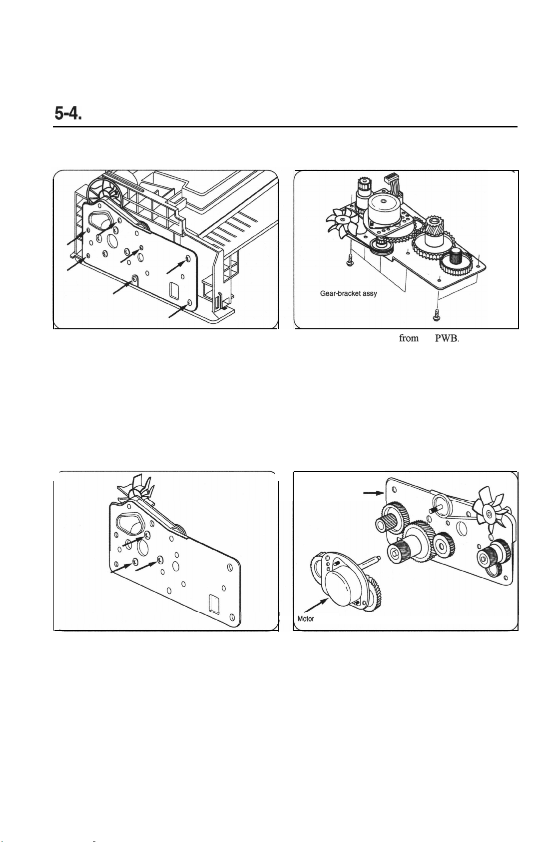
Along the power inlet side of the printer, locate and
remove the seven screws which hold the gear bracket
assembly on the printer.
Detach the motor harness from the
Gear Bracket Assy
M&or Bracket
-_)
PM.
Remove the three screws holding the motor bracket to
the gear bracket assembly and pull the motor away.
Pull up on the gears individually to remove them.
46
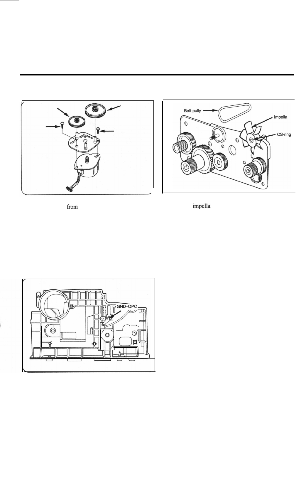
Remove the two screws on the motor bracket to
separate the motor
from
the motor bracket.
On the gear train, remove the belt pulley and CS ring to
remove the
impella.
Other gears on the gear train have
permanently welded gear locks.
The OPC Ground can be removed after taking off the
gear bracket.
47

5-5. LSU Disassemblv
Remove the three screws holding the LSU in the lower
part of the printer.
Detach the 5-pin scanner motor wire then
while you detach the 6-pin LD wire.
lift
the LSU
48

5-6.
Shaft-Exit Disassembly
If you have not already done so, remove the ICU
Shield.
Release
the exit bearing on both sides of the exit shaft.
Roller
Holder exit face down
exht
\
Lift the exit shaft up and away from the printer.
Locate and remove the face down exit spring, face
down exit holder and exit roller.
49

5-7. Top Cover Disassembly
If you have not already done so, remove the printer
cabinet and cap wire panel.
Working on the underside of the top cover, release the
spring hook lever and remove the hook lever.
C/O
B&on
To remove the top cover from the cabinet, remove the
four screws holding the two spring-C/OS.
Pull out the C/O shaft and separate the top cover Tom
the cabinet.
Remove the C/O button by pressing in the hook and
pulling the button and its spring out of the cabinet.
50
 Loading...