

Page 1
10. PortThru (Network Printer Card) Circuit Description
10-1. Introduction
The purpose of the Network Printer Card(PortThru) is to enable the Samsung Printer to function as a network printer.
The PortThru is a plug-in card that plugs into the Samsung Printer. The PortThru provides a Ethernet Local Area
Network interface through which the printer can be connected to the network.
ITEM Description
Novell Netware Version 3.x, 4.x, 5.0
MS Windows Windows 95/98, Windows NT(3.x, 4..x)
Support system
UNIX
AT & T System V(Rel 3.2, Rel 4.2), BSD 4.3 HP-UX(Rel 9.x, Rel 10.x)
SCO 5.x, SUN OS 5.5, SOLARIS 2.5
Macintosh APPLE
Netware IPX/SPX, Pserver, Rprint mode, NDS/Bindery
Windows IPX/SPX, TCP/IP, DLC/LLC
Support protocols UNIX TCP/IP
APPLE EtherTalk Phase 2
Network Management SNMP MIB-II, Private MIB
CPU 32bit RISC controller
Hardware Flash memory 1M byte
RAM 64 Kbyte SRAM / 8M byte DRAM
Interface with
Shared memory 64K byte SRAM
Printer
Logical connection IEEE 802.2 802.3
Attachment 10/100Base-Tx
CPU Samsung NetARM, 33MHz
PHY Chip ICS1892, 25MHz
Flash ROM 1M Byte
Memory
DRAM 8M Byte
SRAM 64K Byte
EEPROM 32K Bit
Printer Interface
NetBridge, 33MHz
60 Pin Connector
Dimension(HxWxD) 15 x 80 x 124mm
Power Consumption Max. 0.6A/ +5Vdc
Product Information
Samsung Electronics 10-1
Page 2
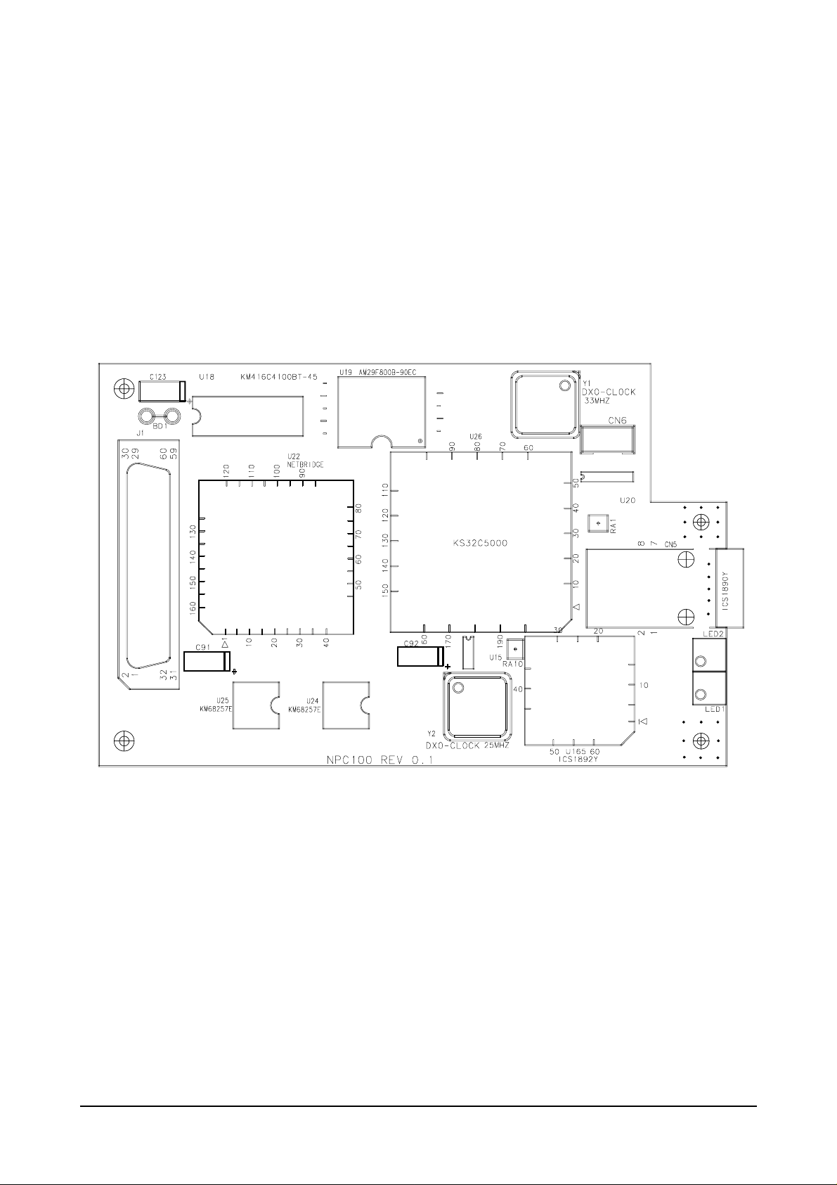
10-2. Board Description
10-2-1 Configuration of Network Board
Service Part : JC92-01119A
Product Information
Samsung Electronics10-2
Page 3
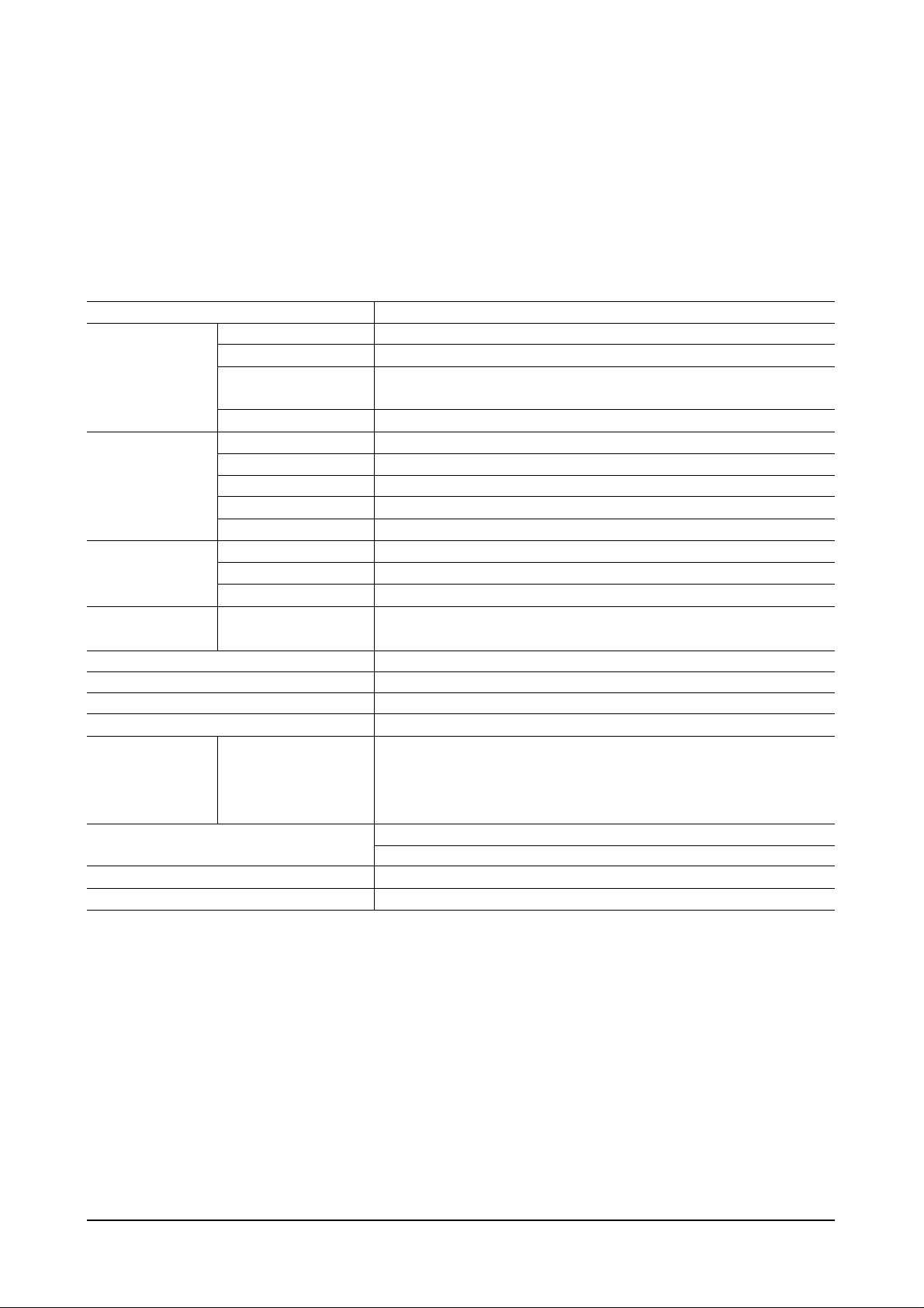
10-2-2 Network Board Connector Pin Assignment
Product Information
Samsung Electronics 10-3
Connector Description Pin No. Idle Active In/Out
21, 19, 18, 17, 37, 44,
Addr 0 ~ Addr 15 42, 40, 38, 36, 34, 32 Pulse Pulse I
30, 28, 26, 24
35, 33, 31, 29, 27, 25
Data 0 ~ 15 23, 22, 14, 13, 11, 10 Pulse Pulse I/O
9, 7, 6, 5
nPrnWait 41 +5V DGND O
PRES_L 57 DGND DGND -
nPrnlrq 15 +5V DGND O
nPrnCS 4 +5V DGND I
nPrnRE 50 +5V DGND I
nPrnWE 51 +5V DGND I
nResetIn 39 +5V DGND I
+5V 3, 58, 59, 60 +5V +5V -
DGND 8, 12, 16, 48, 52, 56 DGND DGND -
RxD 1 +5V Pulse I
TxD 2 +5V Pulse O
+5V 3 +5V +5V -
DGND 4 DGND DGND -
Printer Interface
J1
Serial Connector
CN6
Page 4

10-3 Troubleshooting of Network Card
10-3-1 Troubleshooting Flow Chart
Product Information
Samsung Electronics10-4
Status LED Blinking ?
Does it light up the LEDs?
Turn off power and turn on again in
approx.5 seconds and wait 1 minute.
Go to Power Error
No
Yes
Yes
Yes
Yes
Link LED on ?
Go to System Error
No
Is it possible detecting
using syncThru from PC ?
Is it possible printing
through network ?
Go to Network Error
No
Go to PHY chip Error
No
Go to Shared Memory Interface Error
No
Page 5

Product Information
Samsung Electronics 10-5
Power Error
Network board's input
voltage = +5V ?
Check the BD1 of the Network Card
Power Error
Go to System Error or Network Error
Section
Go to System Error or Network Error
Section
Replace the board
No
Is it short between
+5V and GND in the
Network board?
No
Yes
Yes
Page 6

Product Information
Samsung Electronics10-6
System Error
CPU's input
voltage = +5V ?
CPU's pin No. 82
Reset input level = High ?
Check the Network Board
(1) ROM installing ?
(2) Soldering status ?
Check the TMODE(pin no. 63, 64) input
level : Low
Check the EXTMREQ(pin no. 108) input
level : Low
Replace the board
If you can't repair the board
System Error
Check the filter (BD1)
No
Yes
Yes
Yes
Yes
Yes
No
U19(pin no 12)
and U165(pin no 22)'s
Reset input level = High ?
No
CPU(pin no 80)'s
input Clock = 33MHz ?
Check the Y1, R104 and R113
No
U22(pin no 63)'s
input clock = 33MHz ?
No
Check the soldering status
Check the CPU(pin no 77) and R102
Check the U22's pin no. 75
Reset signal :
Nomally High during operation
Check the connector J1's pin no. 39
Check the U22's pin no. 123
Check the U22's pin no. 75
Reset signal :
Nomally High during operation
CPU : U26
NetBridge : U22
Flash ROM : U19
DRAM : U18
PHY Chip : U165
Page 7

Product Information
Samsung Electronics 10-7
Network Error
U165's input
voltage = +5V ?
U165(pin no 82)'s
Reset input level = High ?
U165(pin no 53)'s
input Clock = 25MHz ?
Check the Network Board
Soldering status ?
Check the R79, R80, R112 and CN5
Check the LED1 and R106
Replace the board
If you can't repair the board
Network Error
Check the filter (L1, L2)
No
Yes
Yes
Yes
No
No
Check the soldering status
Check the Y2, R97 and R105
Check the connector J1's pin no. 39
Check the U22's pin no. 123
Check the U22's pin no. 75
Reset signal :
Nomally High during operation
Page 8

Product Information
Samsung Electronics10-8
PHY Chip Error
U165's input
voltage = +5V
U165(pin no. 82)'s
Reset input level = High ?
U165(pin no. 53)'s
input clock = 25MHz ?
U165(pin no. 36 and 43)'s
input clock = 2.5MHz or 25MHz ?
Check the Network Board
Solering status ?
Check the RA1, RA10, R138, R144
and R145
Check the LAN Cable
Replace the board
If you can't repair the board
PHY Chip Error
Check the filter (L1, L2)
No
Yes
Yes
Yes
Yes
No
No
Check the Y2, R97 and R105
No
Check the Y2, R97 and R105 and
check the soldering status of U165
Check the connector J1's pin no. 39
Check the U22's pin no. 123
Check the U22's pin no. 75
Reset signal :
Nomally High during operation
Page 9

Product Information
Samsung Electronics 10-9
Shared Memory Interface Error
U22's input
voltage = +5V ?
U22(pin no. 123)'s
Reset input level = High ?
U22(pin no. 63)'s
input Clock = 33MHz ?
U22(pin no. 65, 66)'s
input level = Low ?
Check the Network Board
Solering status ?
Check the R68, R69, R70, R72,
R73, R92, R127 and R128
Check the J1 connector and DRAM(U18)
Replace the board
If you can't repair the board
Shared Memory Interface Error
Check the filter (BD1)
No
Yes
Yes
Yes
Yes
No
No
Check the Y1 and R102
No
Check the soldering status of the U22
Check the connector J1's pin no. 39
Reset signal :
Nomally High during operation
Page 10

Product Information
Samsung Electronics10-10
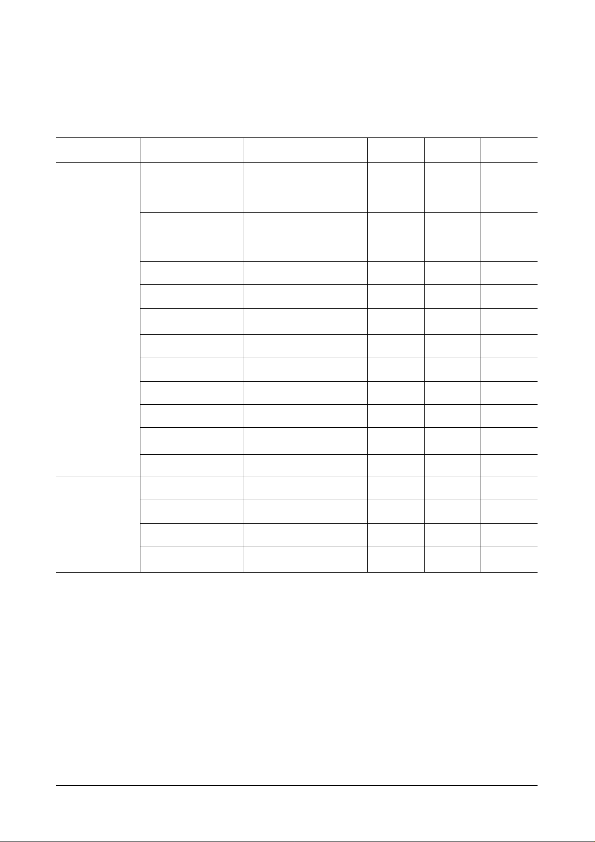
10-3-2 Troubleshooting Table of Network Card
No. Error Type Check List Repair
Power Connection Check the BD1 of Network Card
VCC voltage (nominal is +5V) level Refer to the section of Power Error
1 VCC voltage should be in the range between Troubleshooting
+4.75 and +5.25V
Short between VCC and GND. Repair board
Reset Error : Reset signal is normalhigh during operation
System source clock is 33MHz.
Check point : Y1’s pin 5 and U26’s pin 80 Replace the Y1.
The output clock of U26 is 33MHz. Check the R102 and R122. If these two
2 The input clock of U26 is 33MHz. resistors are OK then replace the board.
Check the ROM Chip select signals
(Pin no U26-75 and U19-26)
Check the DRAM control signals(pin no U26-89, 95, 96,
99, 100 and U18-13, 14, 36, 37, 38)
Reset Error : Reset signal is normal high during operation
Check the Y2, R97 and R105.
The input clock of U165 is 25MHz. If these two resistors are OK then
3 replace the Y2
Check the R79, R80 and R112
Check the output and input signal of U165 of RJ45
connector side. Pin no. 5, 6, 10, 11 of U165.
Check the MII signals between U26 and U165
(Pin no. 30, 31, 32, 33, 34, 35, 36, 37, 38, 42, 43, 44, Refer to the section of PHY chip
4
45, 46, 47, 48, 49, 50) error
Check RA1, RA10, R138, R144 and R145.
The output clock of U26 is 33MHz. Check the R102 and R122. If these two
The input clock of U22 is 33MHz. resistor are OK then replacethe board.
5
Check the Shared Memory Cotrol signals. Refer to the Shared Memory Interface
U22-37, 38, 39 and R68, R69 and R70 Error Section.
The LEDs
does not lit
up
The status
LED does
not blinking
The status
LED is OK
but the
LINK LED
does not lit
up
The two
LEDs are
OK but can’t
detect the
Network
Printer using
SyncThru
from PC
The
SyncThru
can detect
the Network
Printer card
but Printer
does not
printing.
 Loading...