

Samsung ML-7300N Service Manual
ML-7300 Series
LASER PRINTER CONTENTS
SERVICE
Manual
1. Precautions
2. Reference Information
3. Product Information
4. Disassembly
5. Trouble Shooting
6. Exploded Views & Parts List
7. Electrical Parts List
8. Block Diagrams
9. PCB Diagrams
10. Port Thru
(Network Printer Card)
11. schematic diagrams

Samsung Electronics Co., Ltd. September. 2001
Printed in Korea
VERSION NO. : 1.02 P/N. JC-0024A
ELECTRONICS

Contents
1. Precautions
2. Reference Information
3.Product Information
4. Disassembly
1-1 Safety precautions______________________________1-1
1-2 Laser Safety Statement __________________________1-2
2-1 Abbreviations and Acronyms
_____________________2-1
2-2. Diagnostic Control Unit
_________________________2-3
2-2-1. Abstract
________________________________2-4
2-2-2. List of code description
_____________________2-5
3-1 General Specifications ________________________3-1
3-2 Controller Specifications _______________________3-2
3-3 Electrical Specifications _______________________3-2
3-4 Environmental Condition_______________________3-3
3-5 Image Cartridge(Developer) ____________________3-3
3-6 Paper Handling Specifications __________________3-4
4-1 Front View
__________________________________
4-1
4-2 Rear View
__________________________________4-1
4-3 Cabinet Disassembly
__________________________4-2
4-3-1. Cover Right
_____________________________4-2
4-3-2. Cover Left
_____________________________4-4
4-3-3. Cover Front
____________________________4-5
4-3-4. Cover Main
____________________________4-5
4-3-5. Cover Rear
____________________________4-6
4-4 Video Controller board & Joint board
_______________4-7
4-5 Fuser Ass’y
________________________________4-9
4-6 Bracket Motor Ass y & Cover Open Switch Unit
_____4-12
4-7 Pickup Ass’y __________________________________4-14
4-8 Laser Scanner Unit_____________________________4-15
4-9 Multi Purpose Tray _____________________________4-17
4-10 Control Pane_________________________________4-20
4-11 Engine Controller Board ________________________4-22
4-12 SMPS & Bracket Duplex Ass y __________________4-26
4-13 Transfer Roller Ass’y___________________________4-28

ii Samsung Electronics
5. Troubleshooting
6. Exploded Views
& Parts List
7. Electrical
Parts Lists
8- Bloack Diagrams
5-1 Print Quality
________________________________5-1
5-2 HVPS Output Spec _____________________________5-3
5-3 Malfunction____________________________________5-4
5-4 .Connector Pin Assignment
_________________________5-8
5-4-1. Engine Board Connector Pin Assignment
______5-8
5-4-2. Joint Board Connector Pin Assignment
_________5-9
5-4-3. S.C.F Board Connector Pin Assignment ________5-11
5-5 .Troubleshooting of Video Controller
_________________5-12
5-5-1. Troubleshooting Flow Chart __________________5-12
Power Error__________________________________5-13
System Error_________________________________5-14
Engine Error _________________________________5-15
Self Test Error________________________________5-15
Parallel Interface Error _________________________5-16
Printing Error_________________________________5-16
5-5-2. Troubleshooting Table of Video Controller Board__5-16
6-1. Main Ass’y _________________________________6-2
6-2. Cover Ass’y ________________________________6-4
6-3. Frame Ass’y________________________________6-8
6-4. Cassette Ass’y ______________________________6-12
6-5. MP Tray Ass’y ______________________________6-14
6-6. Pick Up Ass’y_______________________________6-16
6-7. Fuser Ass’y ________________________________6-18
6-8. Shield Ass’y ________________________________6-20
6-9. Bracket Duplex Ass’y_________________________6-22
6-10. Bracket Motor Ass’y_________________________6-24
6-11. Frame SCF Ass’y___________________________6-26
6-12. Cassette SCF Ass’y_________________________6-29
7-1. Main Engine PBA ___________________________7-1
7-2. Main Controller PBA ________________________7-5
7-3. FLASH MEMORY PBA _____________________7-8
7-4. PTL PBA __________________________________7-8
7-5. CASSETTE PBA ____________________________7-8
7-6. POSTSCRIPT PBA __________________________7-8
7-7. DISP-PANEL PBA ___________________________7-9
7-8. DISP-LCD PBA _____________________________7-9
7-9. TONER PBA _______________________________7-9
7-10. NETWORK CARD PBA(100BASE) _____________7-10
8-1 WIRING DIAGRAM
___________________________
8-1
8-2 Engine Controller Block Diagram___________________8-2
8-3 Video Controller Block Diagram____________________8-3

iiiSamsung Electronics
9. PCB Diagrams
10. PortThru (Network Printer Card)
Circuit Description
1 1. Schematic Diagrams
9-1. Engine Control & Joint Board _____________________9-1
9-2. Cassette Sensor Board__________________________9-2
9-3. Video Controller Board __________________________9-3
9-4. Panel & LCD Board_____________________________9-4
9-5. PTL (Pre Transfer Lamp) Board ___________________9-5
9-6. SCF(Second Cassette Feeder) Board ______________9-6
9-7. Infrared Adapor Board __________________________9-7
9-8. Flash SIMM Board _____________________________9-8
9-9. Postscript Board _______________________________9-8
9-10. Local Talk ___________________________________9-9
9-11. Serial/IrDA Board_____________________________9-10
10-1. Introduction__________________________________10-1
10-2. Board Description _____________________________10-2
10-2-1 Configuration of Network Board_______________10-2
10-2-2 Network Board Connector Pin Assignment ______10-3
10-3 Troubleshooting of Network Card _________________10-4
10-3-1 Troubleshooting Flow Chart__________________10-4
Power Error __________________________________10-5
System Error _________________________________10-6
Network Error ________________________________10-7
PHY Chip Error _______________________________10-8
Shared Memory Interface Error___________________10-9
10-3-2 Troubleshooting Table of Network Card ________10-10
11-1 Main Circuit Diagram_________________________11-1
11-2 Engine Circuit Diagram_______________________11-13
11-3 Cassette Circuit Diagram _____________________11-19
11-4 Panel Circuit Diagram________________________11-20
11-5 PTL Circuit Diagram _________________________11-21
11-6 SCF Circuit Diagram_________________________11-22

1. Precautions
1-1 Safety precautions
Read each caution carefully
1. Do not use the pinter near water or when exposed to inclement weather.
2. Do not place this printer on an unstable cart, stand or table, the product may fall, causing serious damage to the
product.
3. Slots and openings on the cabinet are provided for ventilation. To ensure reliable operation and to protect the
printer from overheation, do not block or cover any of these openings. Do not place the printer in an enclosure
unless the enclosure providesadequate ventilation.
4. Never push any kind of objects into the printer through the cabinet ventilaition slots as they may touch dangerous
hihg voltage points, create short circuits, cause a fire, or produce an electrical shock. Never spill any kind of
liquid on the printer.
5. Do not place the printer in a lacation where someone may trip on the cord.
6. Select a work surface that is lartge enough to hold the printer.
7. Operate this printer using the power source (110V, 220V, etc) indicated on the marking label. If you are not sure
of the type of power source available, consult your dealer or local power company.
8. If you need to use an extension power cord with this printer, make sure that is uses a three-wire grounded cord
and that the total ampere ratings for all of the products using the extension, do not exceed the extension cord
ampere ration.
9. Do not allow anything to rest on th power cord or data communications cable.
10. Unplug this printer from the wall outlet before cleaning. Do not use liquid cleaners or aerosol sprays. Use a damp
cloth for cleaning.
11. Do not touch the surface of the photo-sensitive drum as marks ro scratches may impair print quality.
12. Do not expose the drum unit to direct light for prolonged periods.
13. Use only standard papers, OHP films and approved envelopes.
Precautions
Samsung Electronics 1-1
2. Reference Information
2-1 Abbreviations and Acronyms
Tables 2-1 and 2-2 List abbreviations and acronyms which may be found in this service manual.
Table 2-1. Abbreviations
Abbv Definition Abbv Definition
amps amperes lb pound(s)
lin linearity
ass’y assembly lock bus lock
badac bad assess mm millimeter(s)
neg negative
bps bits per second od open drain
clk clock OSC oscillator
cm centimeter(s) OUT output
CON connector PIC picture
GND ground pos positive or position
HLDA hold acknowledge pot potential
HLDAR hold acknowledge received psynrq page synchronization request
HLDR hold request pwr power
HOR horizontal qty quantity
in inch(es) or input sw switch
INTA interrupt Acknowledge sync synchronous or
synchronization
INT Interrupt tach tachometer
INTR Interrupt request Vcc collector supply voltage(dc)
I/O Input and Output vert vertical
mpx multiplex Vp-p peak-to-peak voltage
VR variable resistor
Reference
Samsung Electronics 2-1
Table 2-2. Acronyms
Acronym Definition Acronym Definition
ABL Automatic Blanking Limiter IDE Intelligent Drive electronics or
Imbedded Drive Electronics
ACC Automatic Color Control IF Intermediate Frequency
ADC Analog to Digital Converter IPM Images Per Minute
ADS Address/Data Status ISA Industry Standard Architecture
ALE Address-Latch Enable KBC Keyboard Controller
ASCII American Standard Code for LAD Local Address/Data Bus
Information Interchange
BIOS Basic Input/Output System LCD Liquid Crystal Display
BPF Band Pass Filter LED Light Emitting Diode
BPS Bits Per Second MCA Micro Channel Architecture
CCFT Cold Cathode Fluorescent Tube MDA Monochrome Display Adapter
CGA Color Graphics Adapter NC No Connection
CMOS Complementary Metal Oxide NF Noise Figure or Noise Factor
Semiconductor
CPU Central Processing Unit PA Power Amplifier
CRT Cathode Ray Tube PBA Printed Board Assembly
CRU Customer Replacement Unit
DMA Direct Memory Access or PBM Primary Bus Master
Dynamic Memory Address
DMAC Direct Memory Access PCB Printed Circuit Board
Controller
DVM Digital Voltmeter PCMCIA Personal Computer Memory
Card International Association
EEPROM Electronically Erasable Pro- PLCC Plastic Leaded Chip Carrier
grammable read Only Memory
EGA Enhanced Graphics Adapter PMS Power Management System
EISA Extended Industry Standard POST Power On Self Test
Architecture
ESDI Enhanced Small Device PPM Pages Per Minute
Interface
FDC Floppy Disk Controller PQFP Plastic Quad Flat Package
FDD Floppy Disk Drive QFP Quad Flat Package
FL Fluorescent Light(Lamp) RAM Random Access Memory
HDD Hard Disk Drive ROM Read Only Memory
HPF High Pass Filter RTC Real-Time Clock
SCSI Small Computer Systems SBM Secondary Bus Master
Interface
SIO Serial Input/Output Controller TSTN Triple Super Twisted Nematic
SOP Small Outline Package UHF Ultrahigh Frequency
SSOP Shrink Small Outline Package VCO Voltage Controlled Oscillator
STN Super Twisted Nematic VESA Video Electronics Standard
Association
SCC Serial Communications VGA Video Graphics Array
Controller
TFT Thin Film Transistor VHF Very High Frequency
TS Tri-State XO Crystal Oscillator
TSOP Thin Small Outline Package
Reference
Samsung Electronics
2-2
2-2. Diagnostic Control Unit
2-2-1. Abstract
The diagnostic Control Unit(DCU) is useful for troubleshooting the Laser beam printer ML Series engines,
and for checking printer status.
The DCU can be used in common for ML series, but each model has several different code description.
Refer to the code description for ML-7300 in next page.
Reference
Samsung Electronics 2-3
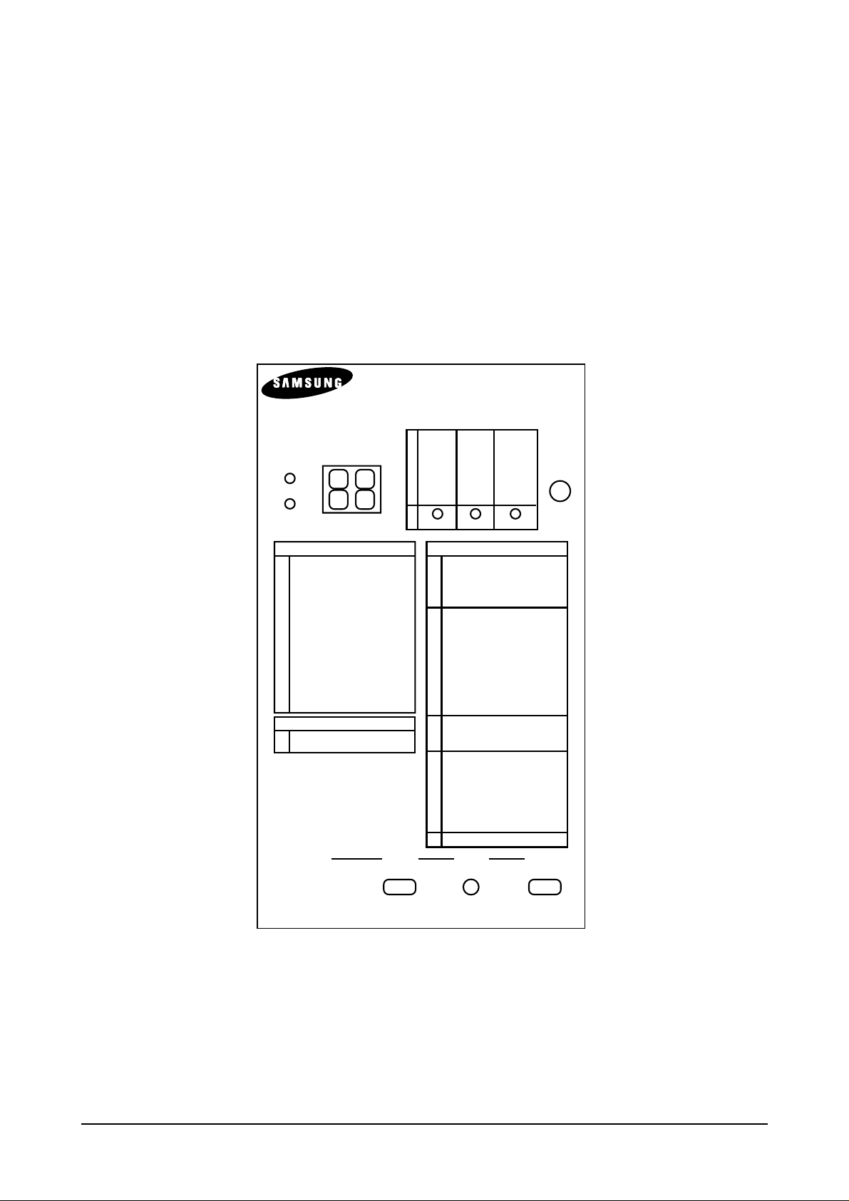
ML-80 DIAGNOSTIC CONTROL UNIT
QUICK REFERANCE
04
05
07
08
09
10
BIAS 3
LSU READY
PAPER EMPTY
COVER OPEN
OVER HEAT
BIAS 1
LSU MT&LD
EXIT SENSOR
PRINT HEAT
BIAS 0
LSU MOTOR
FEED SENSOR
STANDBY HEAT
ON OFF
STATUS
SELF
TEST
DIAGNOSTIC
DIAG NOSTIC CODE
00
01
02
03
04
05
06
07
08
09
10
11
12
13
14
MAIN MOTOR OPERATION
MAIN HIGH VOLTAGE ON
TRNSFER HIGH VOLTAGE (-)ON
THV(+) REFERANCE VOLTAGE
DEV/SUPPLY V OL TAGE ON
LSU OPERATING TEST
PICKUP CLUTC ON
PAPER EMPTY SENSOR TEST
FEED & EXIT SENSOR TEST
COVER OPEN SENSOR TEST
FUSER TEST
HOT BURN TEST
CLEAN (MESSAGE)PRINT
THV (+) TRIGGER & THV ON
THV (+) DUTY
GREEN STATUS CODE
8899GREEN MODE READY
GREEN MODE WARM UP
STATUS CODE
00
01
02
03
04
20
21
23
30
31
33
34
40
43
47
50
60
62
68
61
64
69
70
71
72
73
90
95
READE (LEGAL)
READE (LETTER)
READE (A4)
READE (EXECUTIVE)
READE (B5)
PRINT START
PRINT START (MAMUAL)
PRINT START (2'nd PAPER)
FEED SENSOR 1'st ON
FEED SENSOR 1'st OFF
FEED SENSOR 1'st ON (2'nd PAPER)
FEED SENSOR 1'st OFF (2'nd PAPER)
FEED SENSOR 2'st ON
FEED SENSOR 2'st ON (2'nd PAPER)
FEED SENSOR 2'st OFF
PAPER OUT
OPEN FUSER ERROR
LOW HEAT ERROR
OVERHEAT ERROR
WARM UP
COVER OPEN ERROR
SLEEP MODE
NO PAPER or CASSETTE
PAPER JAM 0
PAPER JAM 1
PAPER JAM 2
MANUAL PRINT MODE
LSU NOT READY
* THE CONTROL CODES 13 & 14
ARE USEFU FROM THE EPROM
VERSION 5. X. X. FOR THE
ENGINE BOARD
DCU MODE DOWN SHIFT STOP
UP ENTER
IF YOU ENTER THE DCU MODE
TURNTHEPOWER SWITCH ON WITH HOLDING THREEKEYS DOWN
< Fig 1-1. ML-80 DCU >
2-2-2. List of code description
Reference
Samsung Electronics
2-4
Code Description
1. DIAGNOSTIC CODE 2.STATUS CODE
00 MAIN MOTOR OPERATING 78 SYSTEM ERROR
01 MAIN HIGH VOLT ON / OFF TEST 00 Ready to print from LEGAL paper tray
02 THV (-) ON / OFF TEST 01 Ready to print form LETTER paper tray
03 THV (+) ON / OFF TEST 02 Ready to print form A4 paper tray
04 DEV, SUPPLY ON / OFF TEST 03 Ready to print form EXEC paper tray
05 LSU OPERATING TEST 04 Ready to print from B5 paper tray
06 PICK UP CLUTCH ON 05 Ready to print from FOLIO paper tray
07 PE, DS1, DS2 SENSOR TEST 20 PRINT START (1st CASSETTE)
08 MP, EXIT, FEED SENSOR TEST 21 PRINT START (MULTI PURPOSE)
09 TOP & REAR COVER OPEN, 22 PRINT START (2’nd CASSETTE)
OUT BIN SENSOR TEST 23 PRINT START (DUPLEX)
10 FUSER TEST 50 PAPER OUT
11 HOT BURN TEST 60 OPEN FUSER ERROR
12 DUPLEX CLUTCH TEST 62 LOW HEATER ERROR
13 MULTI PURPOSE CLUTCH TEST 68 OVER HESTER ERROR
14 THERMISTOR 2 TEST 61 WARM-UP
15 PAPER SIZE SENSOR TEST 64 COVER OPEN ERROR
16 FAN SPEED TEST 69 SLEEP MODE
17 PTL TEST 70 NO PAPER or CASSETTE
71 PAPER JAM “0”
72 PAPER JAM “1”
73 PAPER JAM “2”
74 DUPLEX JAM “1”
75 DUPLEX JAM “2”
76 OUT BIN FULL
95 LSU NOT READY
2-2-3. The Diagnostic Control Unit (DCU) Operating Guide
The DCU has functions as follows:
1) Engine Status and Error Code Display mode
Display the engine status and error status code. Refer to List of Code Description.
2) Self-Test mode.
When the engine is ready, this button starts printing a streak pattern.
3) Green mode
Transfer high Voltage adjustment mode
With the power off, hold down the Self-Test button and turn on the pinter. Continue holding down the button
for 4 seconds to start Green mode.
4) Diagnostic Control mode.
With the power off, hold down the 3 button (up/down, shift, stop/enter) and turn on the printer
Continue holding down the button for 5 seconds to start Diagnostic Control mode on the engine.
The DCU has three diagnostic control buttons.
UP : Steps the function of the other two buttons:
SHIFT : Controls the function of the other two buttons:
SHIFT+UP means step down and SHIFT+START means stop.
START : Starts or stops the current diagnostic test.
Code Key Operation LED Display
00 ENTER Run Main Motor Lighten ON LED
SHIFT+STOP Stop Main Motor Lighten OFF LED
UP Increment DCU Code No. (01, MHV)
SHIFT+DOWN Decrement DCU code No. (13, MP)
01 ENTER MHV ON Lighten ON LED
SHIFT+STOP MHV OFF Lighten OFF LED
UP Increment DCU Code No. (02, THV Negative)
SHIFT+DOWN Decrement DCU code No. (00, Main Motor)
02 ENTER THV Negative ON Lighten ON LED
SHIFT+STOP THV Negative OFF Lighten OFF LED
UP Increment DCU Code No. (03, THV)
SHIFT+DOWN Decrement DCU code No. (02, MHV)
03 ENTER THV ON Lighten ON LED
SHIFT+STOP THV OFF Lighten OFF LED
UP Increment DCU Code No. (04, Dev)
SHIFT+DOWN Decrement DCU code No. (02, THV Negative)
04 ENTER DEV, SUPPLY ON Lighten ON LED
SHIFT+STOP DEV, SUPPLY ON Lighten OFF LED
UP Increment DCU Code No. (05, LSU)
SHIFT+DOWN Decrement DCU code No. (03, THV)
05 ENTER LSU Motor On Lighten 3rd LED
UP LSU Ready and LD On Lighten 1, 2nd LED
SHIFT+STOP LSU Motor OFF
UP Increment DCU Code No. (06, Pickup Clutch)
SHIFT+DOWN Decrement DCU code No. (04, Dev)
Reference
Samsung Electronics 2-5
Code Key Operation LED Display
06 ENTER Pickup Clutch ON Lighten ON LED
SHIFT+STOP Pickup Clutch OFF Lighten OFF LED
UP Increment DCU Code No. (07, Sensor TEST)
SHIFT+DOWN Decrement DCU code No. (06, Pickup Clutch)
07 No Action Paper Empty Sensor ON/OFF 1st LED ON/OFF
No Action Duplex 1 Sensor ON/OFF 2nd LED ON/OFF
No Action Duplex 2 Sensor ON/OFF 3rd LED ON/OFF
UP Increment DCU Code No. (08, Sensor TEST)
SHIFT+DOWN Decrement DCU Code No. (06, Pickup Clutch)
08 No Action Multi Purpose Sensor ON/OFF 1st LED ON/OFF
No Action Exit Sensor ON/OFF 2nd LED ON/OFF
No Action Feed Sensor ON/OFF 3rd LED ON/OFF
UP Increment DCU Code No. (09, Sensor TEST)
SHIFT+DOWN Decrement DCU Code No. (07, Sensor TEST)
09 No Action Cover Open Sensor ON/OFF 1st LED ON/OFF
No Action Cover Open Sensor ON/OFF 2nd LED ON/OFF
No Action Out Bin Sensor ON/OFF 3rd LED ON/OFF
UP Increment DCU Code No. (10, Fuser TEST)
SHIFT+DOWN Decrement DCU Code No. (08, Sensor Clutch)
10 ENTER Fuser ON Lighten ON LED
SHIFT+STOP Fuser OFF Lighten OFF LED
UP Increment DCU Code No. (04, Dev)
SHIFT+DOWN Decrement DCU code No. (02, THV Negative)
12 ENTER Duplex Clutch ON Lighten ON LED
SHIFT+STOP Duplex Clutch OFF Lighten OFF LED
UP Increment DCU Code No. (13, MP Clutch)
SHIFT+DOWN Decrement DCU code No. (11, Self-Test)
13 ENTER Multi Purpose Clutch ON Lighten ON LED
SHIFT+STOP Multi Purpose Clutch OFF Lighten OFF LED
UP Increment DCU Code No. (14,Thermistor 2 Test)
SHIFT+DOWN Decrement DCU code No. (12, Duplex Clutch)
14 No Action Temperature 15 1st LED ON
No Action 15 Temperature 30 2nd LED ON
No Action Temperature 30 3nd LED ON
No Action Thermistor 2 Open All LED ON
No Action Thermistor 2 Short All LED OFF
UP Increment DCU code No.
(15, Cassette sensor TEST)
SHIFT + DOWN Decrement DCU Code No. (13, MP Clutch TEST)
15 No Action Cassette Sensor 1 ON/OFF 1st LED ON/OFF
No Action Cassette Sensor 2 ON/OFF 2nd LED ON/OFF
No Action Cassette Sensor 3 ON/OFF 3nd LED ON/OFF
UP Increment DCU Code No. (16, Fan Speed TEST)
SHIFT + DOWN Decrement DCU Code No. (14, Thermistor 2 Test)
16 Enter Fast Speed
UP Low Speed 2nd LED ON/OFF
SHIFT + STOP Fan OFF 3nd LED ON/OFF
UP Increment DCU Code No. (17, PTL TEST)
SHIFT + DOWN Decrement DCU Code No. (15,
Cassette sensor TEST
)
17 Enter Dark Light
UP Bright Light 2nd LED ON/OFF
SHIFT + STOP Light OFF 3nd LED ON/OFF
UP Increment DCU Code No. (00, Main Motor)
SHIFT + DOWN Decrement DCU Code No. (16,
Fan Speed TEST
)
Reference
Samsung Electronics
2-6
3 Product Information
Specifications are correct at the time of printing. Product specifications are subject to
change without notice. See below for product specifications.
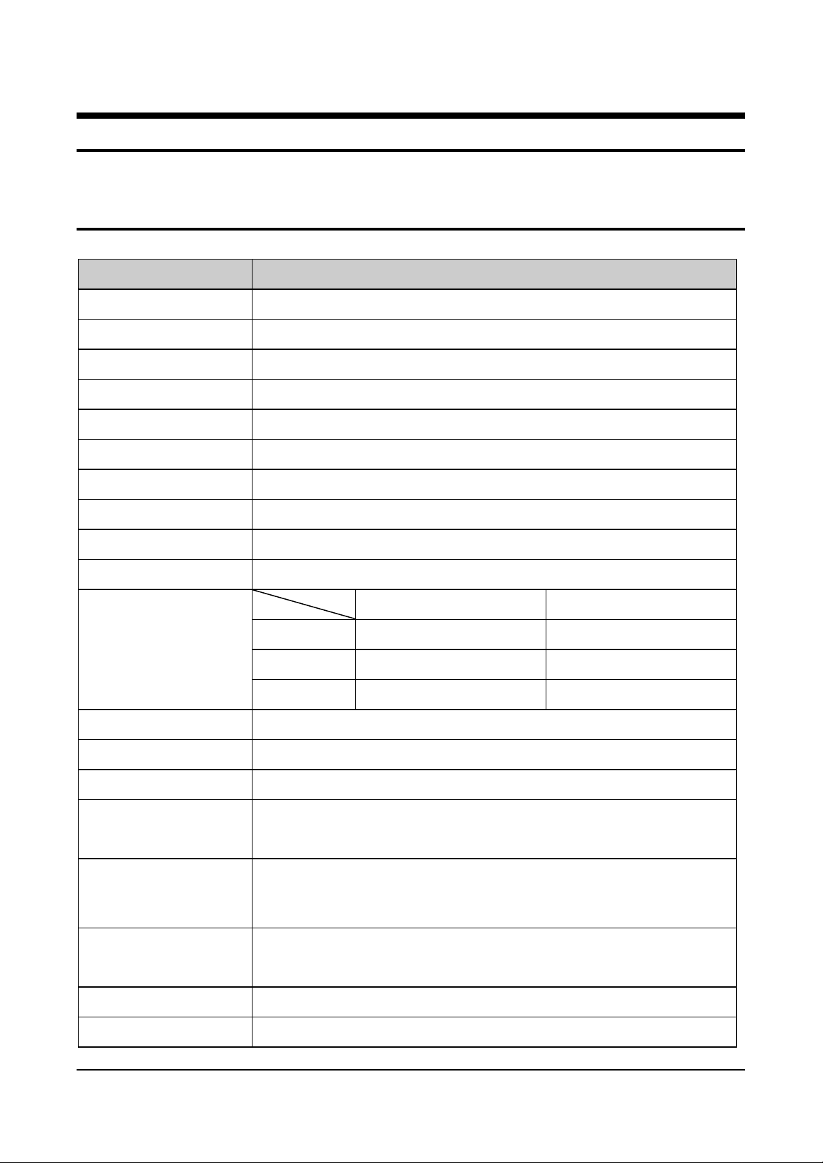
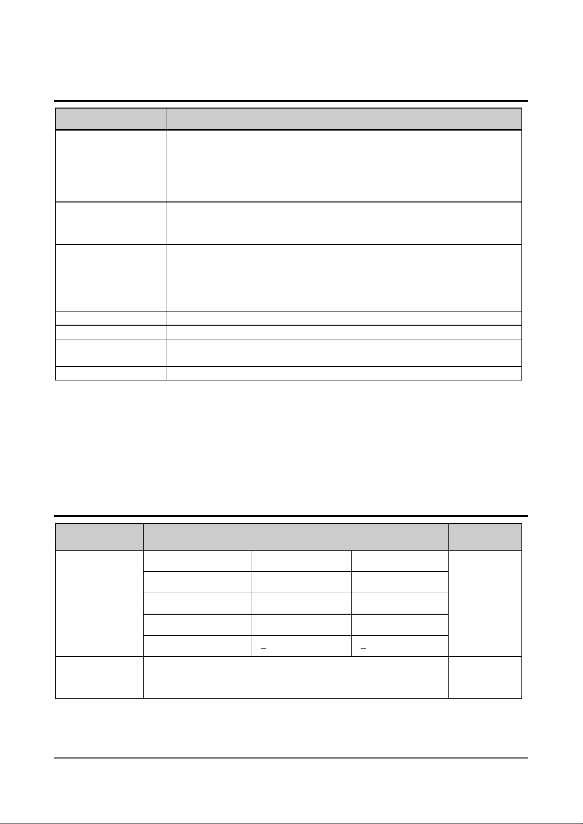
3-1 General Specifications
Item Description
Print Method •Non-impact Electro-photography
Transfer system •Conductive roller transfer
Developing • Non-Magnetic, Mono-Component Toner, Ozoneless
Fuser Unit(Toner fix) • Pressure and Heating with Lamp
Print Speed • 20ppm : A4 size , 5% Character pattern
Resolution • Addressable 1200 X1200 dpi
Source of Light • Laser diode (LSU : Laser Scanner Unit)
Warm-Up Time • Power-on boot : 70 seconds or less
First Print Time • 12 seconds or less
Feed Method • Cassette & Manual , Option Feeder
A4 Letter
Top 4mm 0.20”
Print Margin
Bottom 4mm 0.25”
Left & Right 4mm 0.25”
Print Width Min: 75mm Max: 213
Print Length Min: 148mm Max: 356
Dimension(W X D X H) • 427 X 442 X 301(without option cassette feeder)
• Net : 16.5 Kg(Max.)
Weight
• Gross : 18.5 Kg (Max.)
•Stand by : Less than 30 dB
Acoustic Noise
Certification &
•Printing : Less than 50 dB
•Sleep mode : Background Noise
•110V : UL, CSA,FDA,FCC Part15
Compliance
Power save mode •Enable
Toner save mode •Enable
Samsung Electronics 3-1
•220V : TUV,CE
Product Information
3-2 Controller Specification
Item Description
Processor(CPU) •Motorola Power PC 603e 100Mhz
•ROM : 2MB flash
Memory
Emulation
Interface
Interface switching •Automatic
Interface time-out •5min(Max.)
Font
Compatibility •Dos, Win 3.1 / 9.5/9.8/2000,WinNT4.0,Linux,iMac
•RAM : 16MB
•Option SIMM module :8,16,32,64MB (standard EDO RAM)
•EEPROM :512byte
•PCL6: win 3.1/95/98/200 , win NT 4.0
•Postscript Lever3: win 95/98 PPD , win NT4.0 PPD , Mac PPD
•PCL5e: Linux
•Parallel :IEEE1284
•Serial : RS232C
•Local Talk
•IrDA(Infra-Red Adaptor connector)
• Network Interface : 100 Base T(Auto select),Ethernet
•45 Scalable Font , 1 Bitmap Font
•Postscript 3 internal font 136
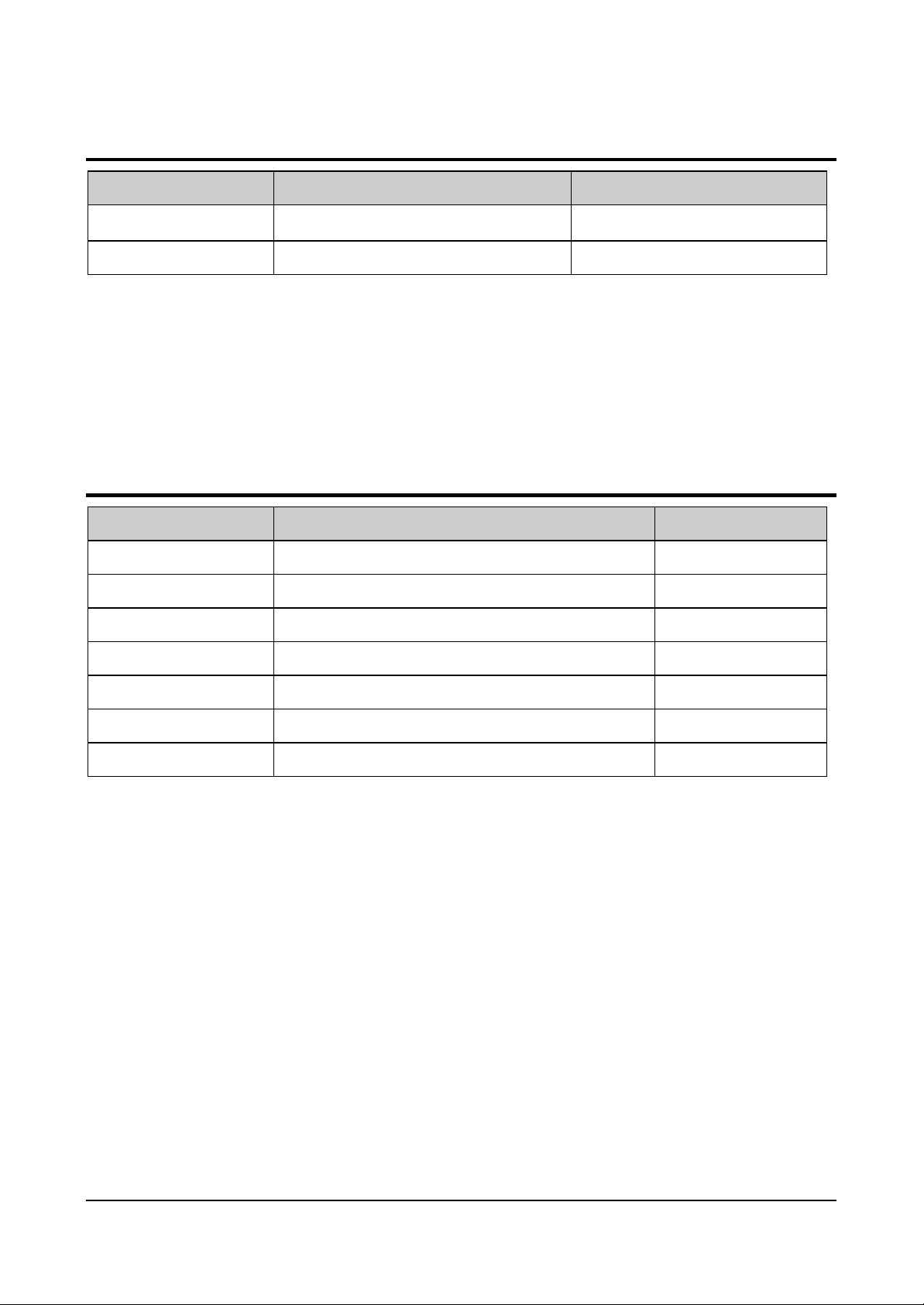
3-3 Electrical Specification
Item Description Remark
Low-voltage mode High-voltage mode
Nominal input voltage 100-120 VAC 200-240 VAC
Input Voltage
Power
Consumption
3-2 Samsung Electronics
Input voltage range 90-132 VAC 189-264 VAC
Nominal frequency 50/60 MHz 50/60 MHz
Frequency tolerance +3Hz +3Hz
•340W Avg or less
•Sleep mode : 30W Avg or less
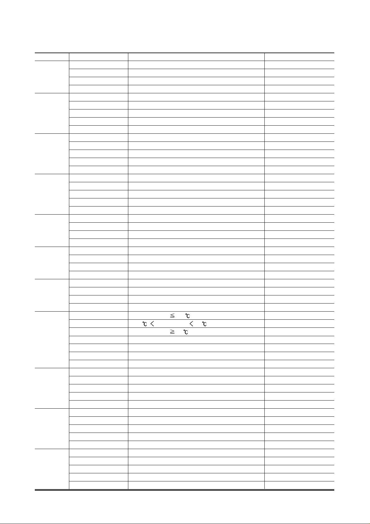
3-4 Environmental Condition
Item Operating Storage
Product Information
Temperature
Humidity • 20~80%RH • 10~80%RH
• 10~30℃(50-86℉) •0~40℃(32-104℉)
3-5 Image Cartridge (Developer)
Item Description Remark
Life span •Running : 10,000 sheets 5% pattern A4 page
Developing • Non-magnetic Contact Developing
Charging • Conductive Roller Charging
Toner supply Method • Exchange the Developer
Toner checking sensor • Enable
Ozone •0.1PPM or less 8hours
Style •Single cartridge
Samsung Electronics 3-3
Product Information
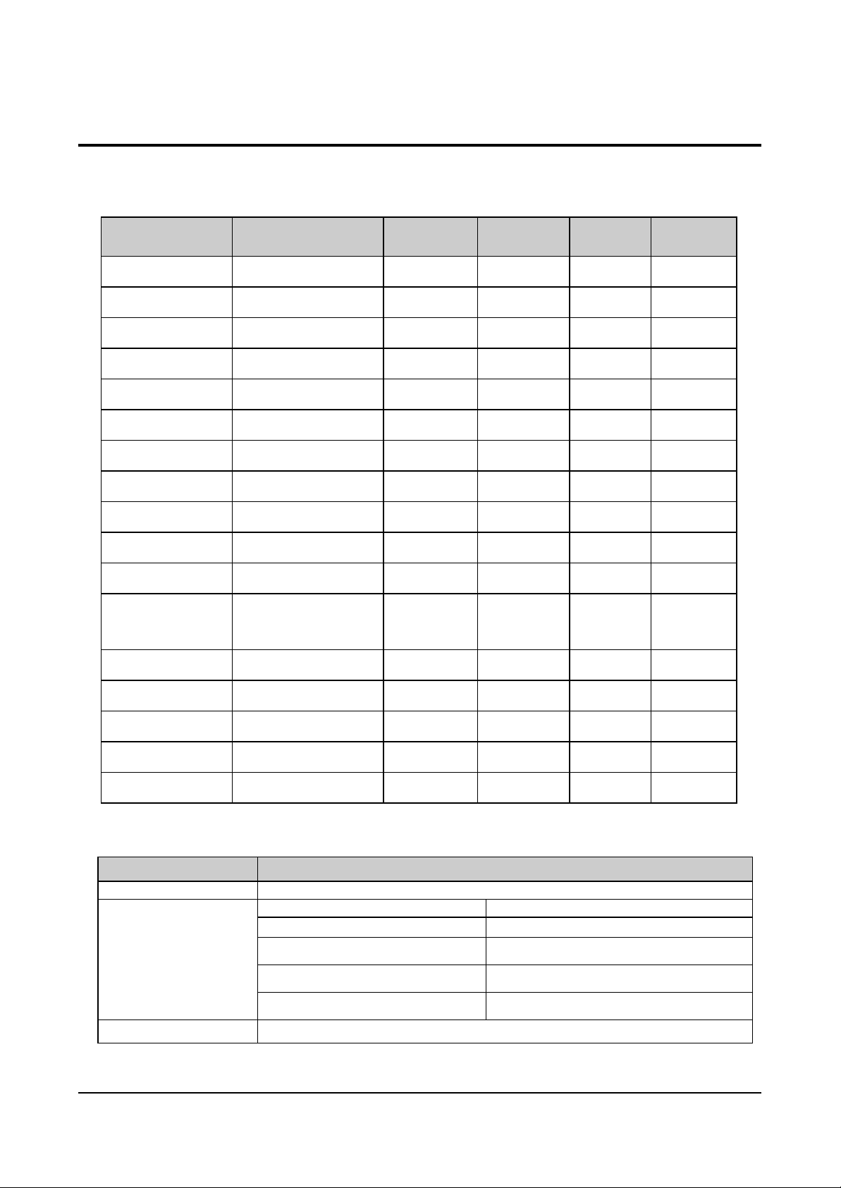
3-6 Paper Handling Specifications
•Input Paper Size
Paper Type Size
1st Cassette 2nd Cassette MP tray Duplex
A4
Letter
Folio(Legal13”)
Legal(Legal14”)
Executive
Statement
ISO B5
JIS B5
A5
A6
Com-10 Envelope
Monarch
Envelope
DL Envelope
210 X 297 mm
216 X 279(8.5 X 11”)
216 X 330(8.5 X 13”)
216 X 356(8.5 X14”)
184 X 267((7.25 X10.5”)
140 X 216(5.5 x8.5”)
176 X 250
182 X257
148.5 X 210
105 X148.5
105 X 241(4.15 X 9.5”)
98 X191(3.87 X 7.5”)
110 X 220(4.33 X 8.66”)
O O O O
O O O O
O O O O
O O O O
O O O
O
O O O
O O O
O O
O O
O O
O O
O O
C5 Envelope
C6 Envelope
Transparency(OHP)
Label paper
162 X 229(6.38 X 9.01”)
114 X 162(4.49 X 6.38”)
A4 or Letter
A4 or Letter
•Feed capacity
Item Description
Cassette 500sheets
Paper 100 sheets
Transparencies 30 sheets
MP tray
Option Cassette 500sheets
Envelopes 10 sheets
Card stocks 10 sheets
Labels 25 sheets
O O
O
O
O
3-4 Samsung Electronics
4. Disassembly
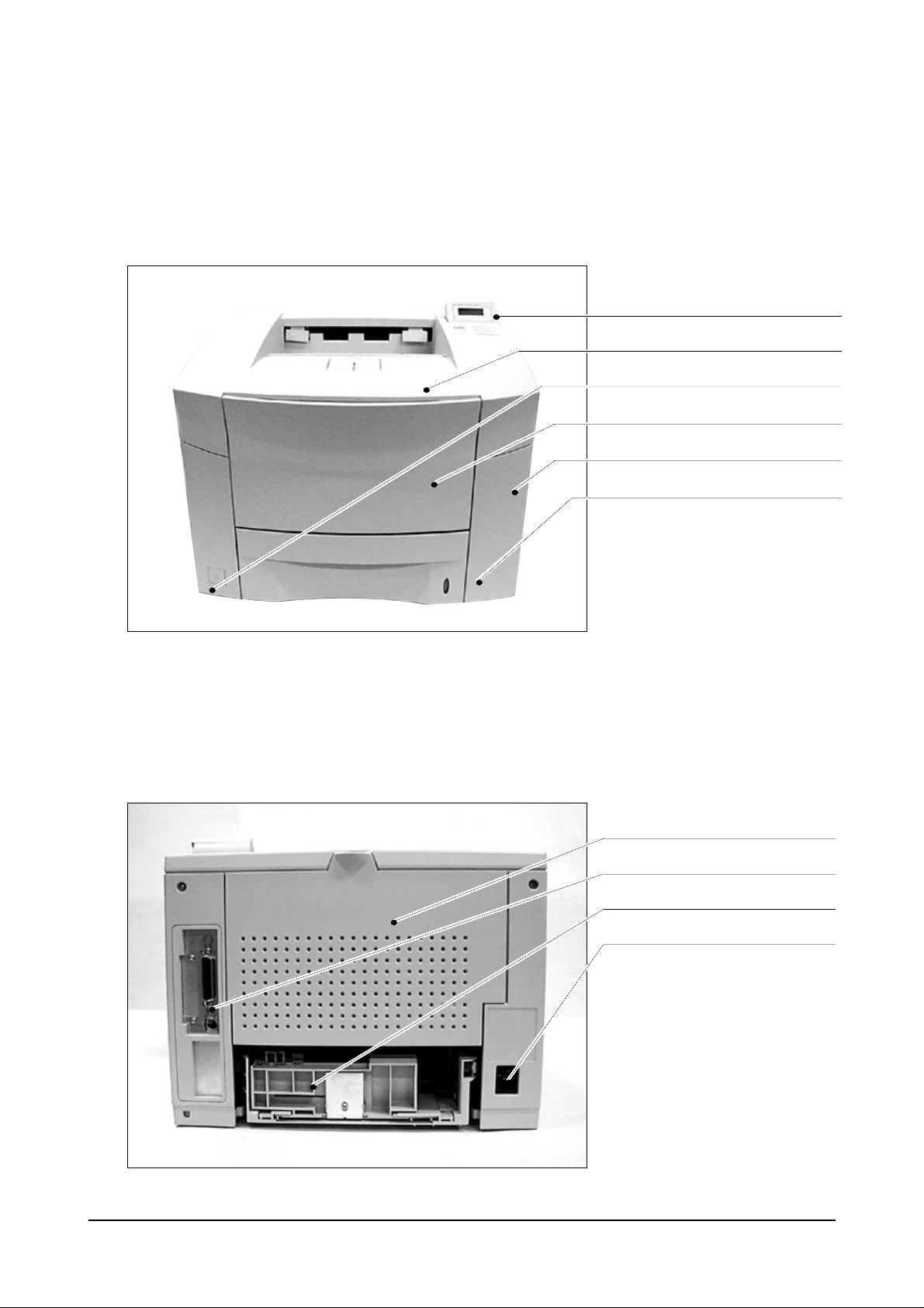
4-1 Front View
4-2 Rear View
Disassembly
Samsung Electronics 4-1
Control Panel
Cover Open
Cover Front
Cover Tray
Power Switch
Paper Level Indicator
Cover Rear
Controller
Cassette
Power Inlet
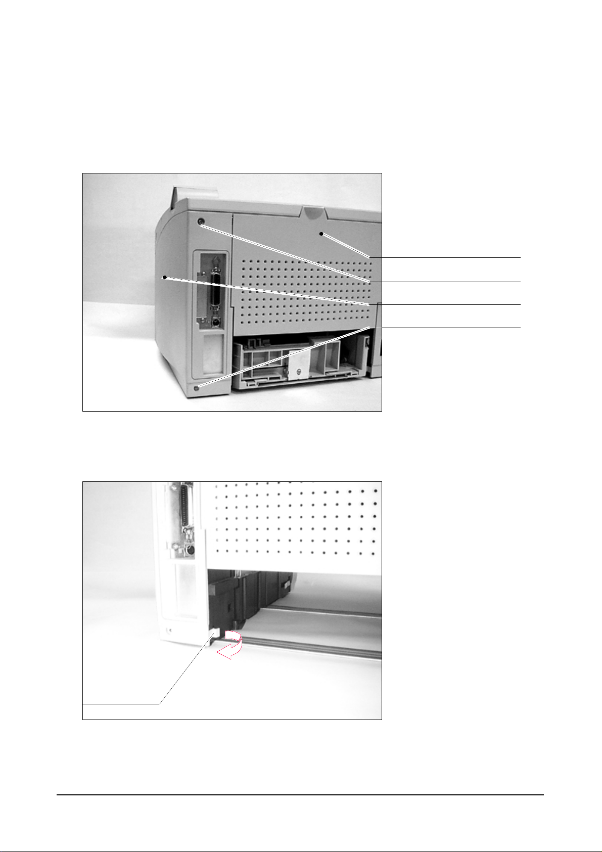
4-3 Cabinet Disassembly
4-3-1. Cover Right
Disassembly
Samsung Electronics4-2
Remove the screws and open the
Cover Rear.
In order to remove the Cover Right.
Please see the hook which locks
the cabinet to the frame, right hand
should first grab the hook and pull it
out for releasing the hook from the
frame.
Screw
Cover Rear
Cover Right
Screw
Hook
Disassembly
Samsung Electronics 4-3
The left hand should slide the
Cover Right to the backward.
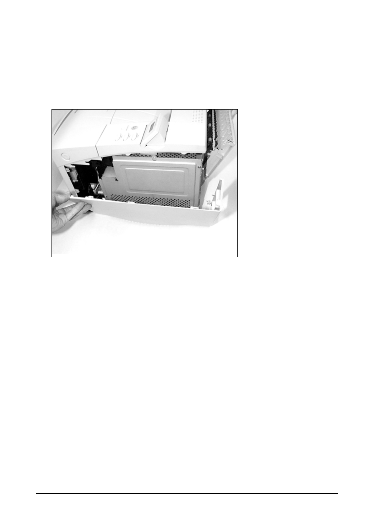
4-3-2. Cover Left
Disassembly
Samsung Electronics4-4
Remove screw and open the Cover
Rear.
Please see the hook of the Cover
Left. Pull the Hook and release it
from the frame.
Slide the Cover Left to the
backward with pulling the hook out.
The Cover Left can be easily
removed.
Pull
Hook
Screw
4-3-3. Cover Front
Please see the MP tray disassembly. (4-9)
4-3-4. Cover Main
Disassembly
Samsung Electronics 4-5
Open the Cover Open.
Remove two screws.
See the hooks.
Push the hooks up and pull them
upward.
With holding Cover Main, remove
the panel wire.
Cover Open
Screw
Cover Top
Screw
Cover Main
Up
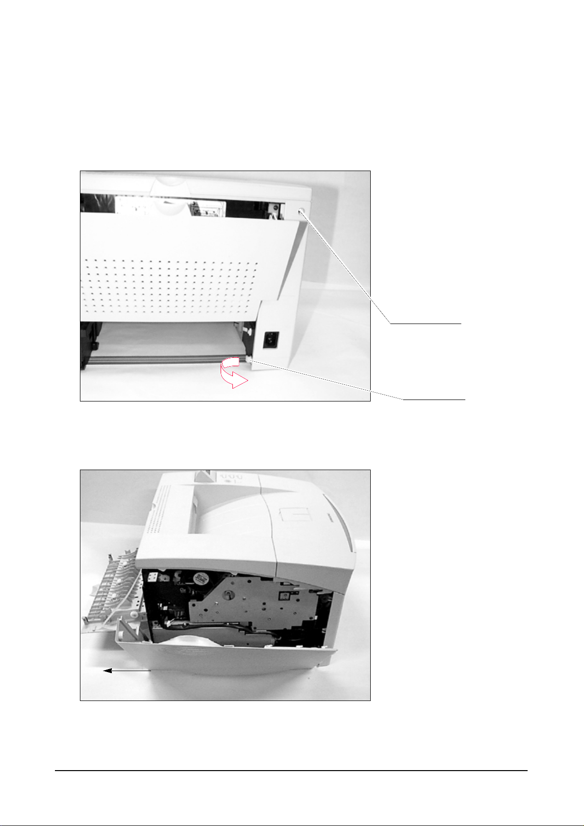
4-3-5. Cover Rear
Disassembly
Samsung Electronics4-6
Open the Cover Rear.
Detach the stripe by pushing the
stripe.
There is a hook holding the stripe.
After detaching the stripe from the
Cover Rear,
Release the Cover Rear from the
hinge.
Cover Rear
Stripe
Ground ICU
Hinge
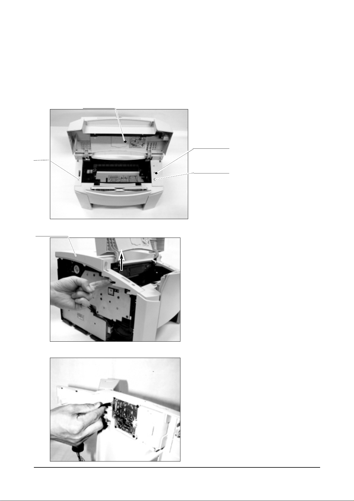
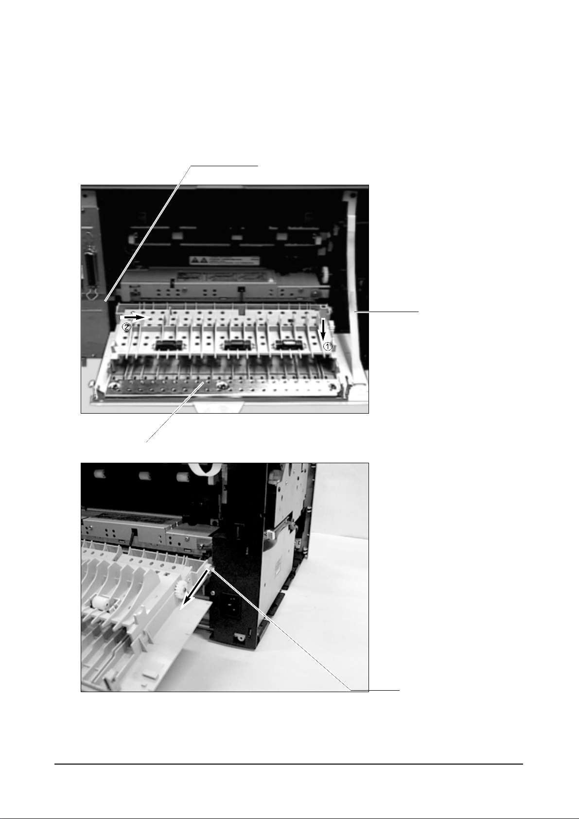
4-4 Video Controller board & Joint board
Disassembly
Samsung Electronics 4-7
After removing external cabinet,
see the 5 screws and you should
remove them.
The Shield ICU is important for EMI
and protection for Controller.
After removing Shield ICU, you can
see the assembled controller.
Unplug the panel cable and engine
I/F cable with care and remove the
screws from the frame.
Joint Board
Panel Cable
Frame ICU
RAM Simm Socket
Controller Board
Engine I/F cable
Flash SIMM or
Postscript SiMM
Socket
Shield ICU
Screw
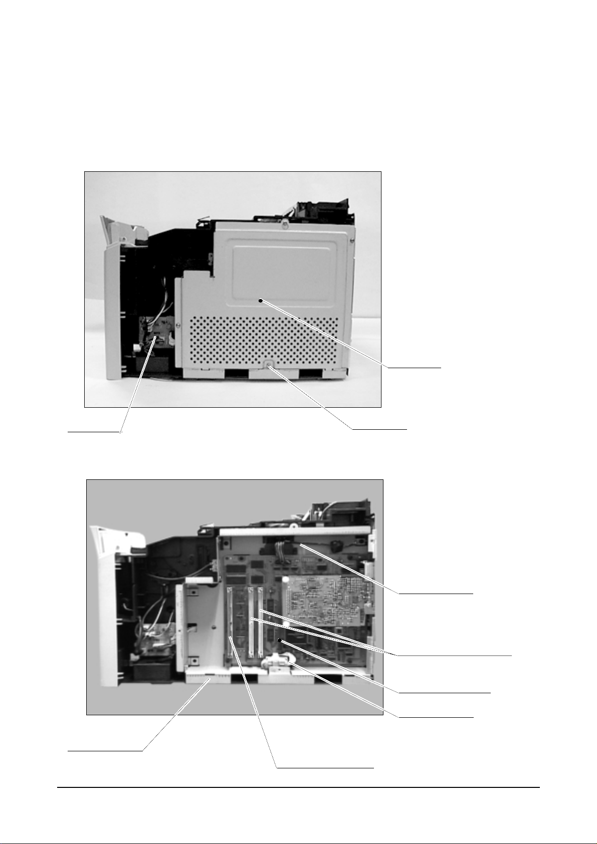
Disassembly
Samsung Electronics4-8
Remove the screws which hold the
Bracket ICU to the frame and
detach controller from the frame.
You can see the Frame ICU.
Screw
Screw
Reserved for
Serial
Parallel I/F
Reserved for
Network
Ground ICU
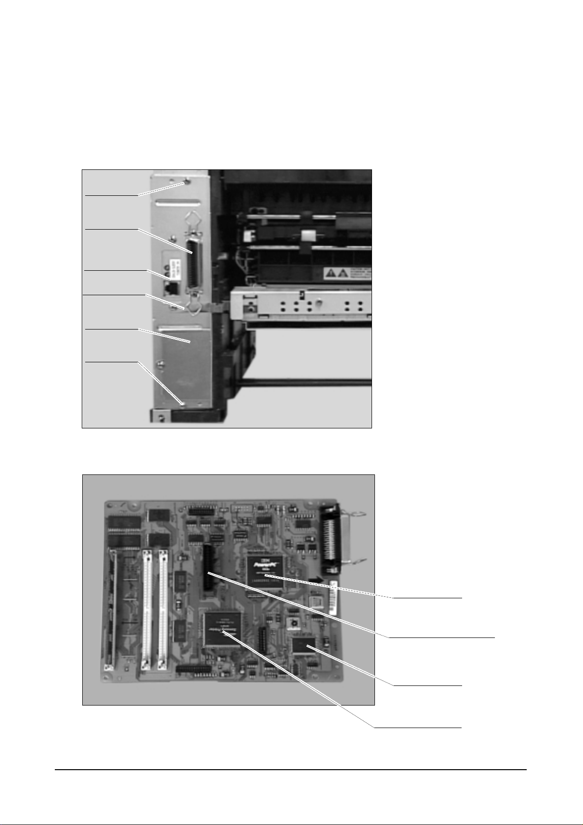
CPU
Connector for Network
ASIC (SPGP1)
Video Controller Board
Hyper chip
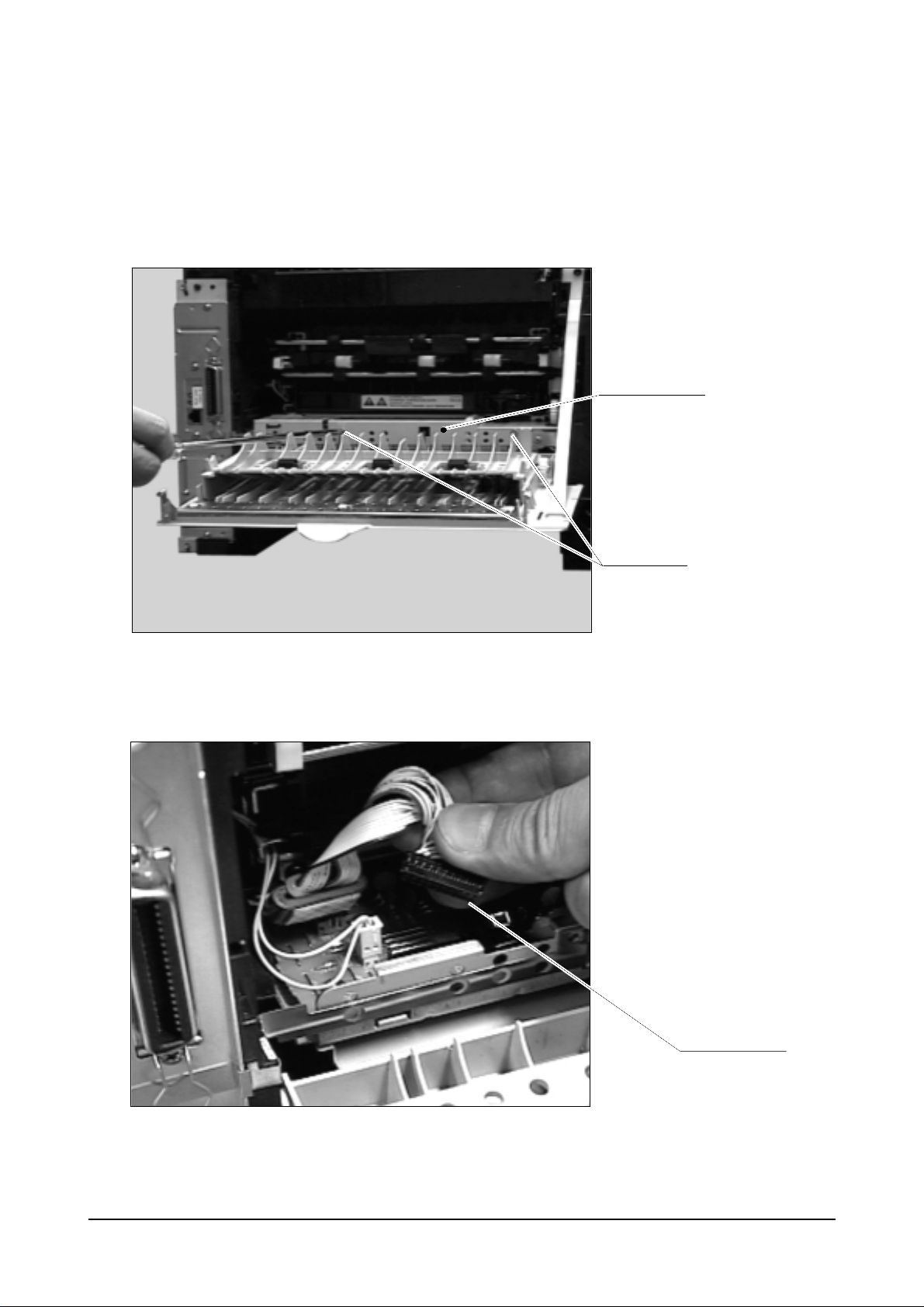
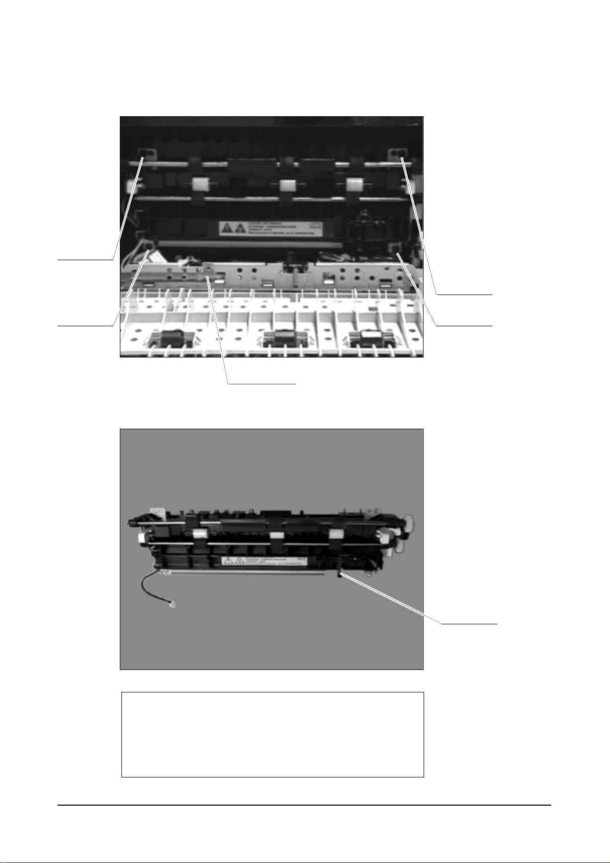
4-5 Fuser Ass’y
Disassembly
Samsung Electronics 4-9
Open the Cover Rear and see the
screws and unscrew and remove
the Cover pcb.
After removing the Cover pcb,
unplug the Thermistor connector
from the Engine Board.
Screw
Cover PCB
for engine B’d
Thermistor
connector
Disassembly
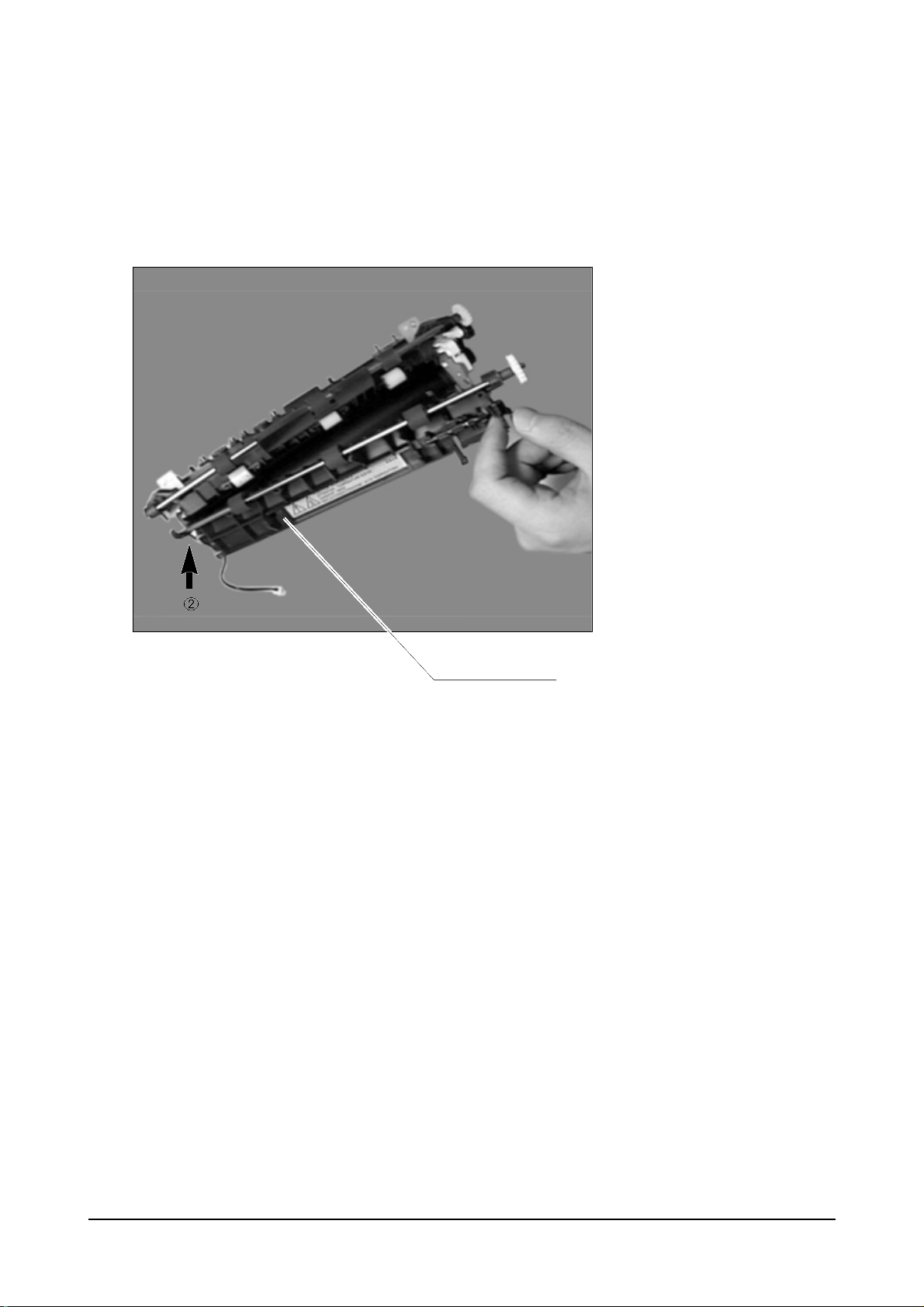
Samsung Electronics4-10
See the 4 screws which hold
the fuser ass'y to the frame.
You should unscrew and pull
the fuser out and it will be
removed.
The AC connector for fuser
is
designed to be directly
connected to the AC socket
which is positioned in the
frame.
Notice : After you confirm exactly SEC. code,
you have to exshange the defective
“Fuser ass’y” for goods
=> Do use the exclusive “Fuser ass’y” in the ML-7300 model
(ML-7300 model is different from ML-7000 & ML-7050)
Screw
Screw
exit sensor
actuator
< Fuser Ass’y >
Screw
Screw
Ground ICU
Disassembly
Samsung Electronics 4-11
When Jam happens, you can easily
remove it by pulling the Guide Rear
out like figure. In order to remove
Guide Rear, opening the Guide
Rear out like figure and pull out
hinge of Guide Rear.
Guide Rear
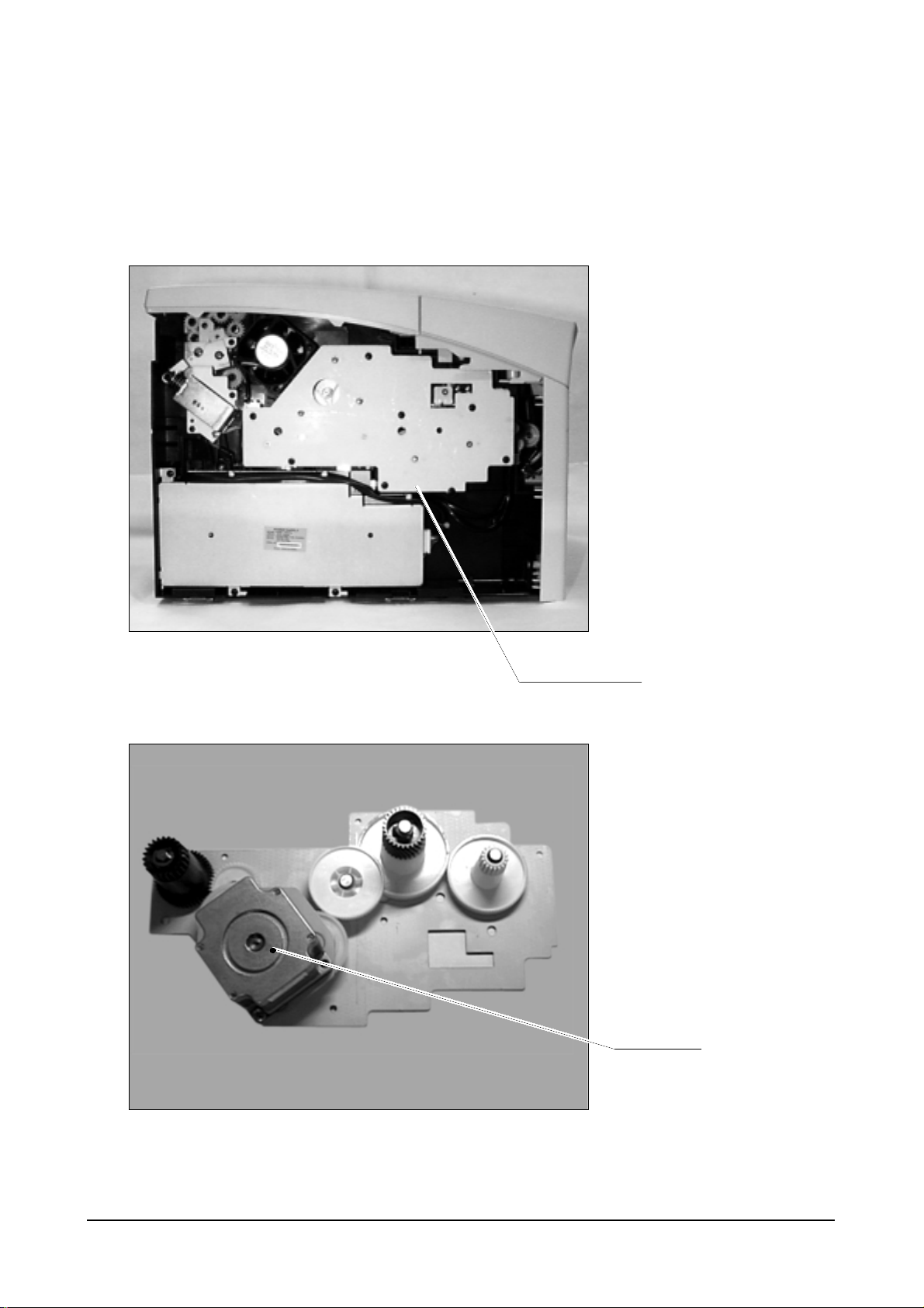
4-6 Bracket Motor Ass’y & Cover Open Switch Unit
Disassembly
Samsung Electronics4-12
Bracket Motor ass’y is located in
the right-upper side. Remove 7
black screws and detach the ass’y
from the frame and unplug the
motor connector from the motor.
You can see the Bracket Motor ass’y.
Motor and several gears are
assembled in one gear bracket.
Bracket Motor Ass’y
Motor
< Bracket Motor Ass’y >
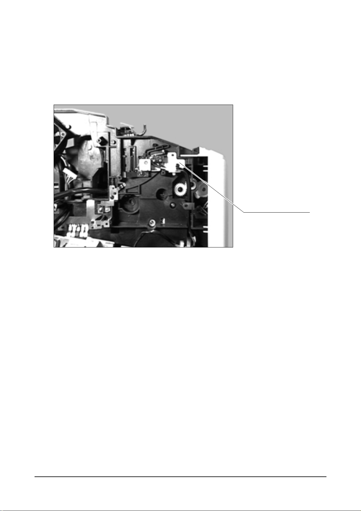
Disassembly
Samsung Electronics 4-13
After removing the Bracket Motor
ass’y, you can see the Cover Open
Switch Unit.
Remove the SMPS.
Refer to SMPS & Bracket
Duplex Ass’y disassembly (4-12)
Detach two Connectors form the
SMPS.
Remove 2 screws and detach the
unit from the frame.
Cover Open Switch unit
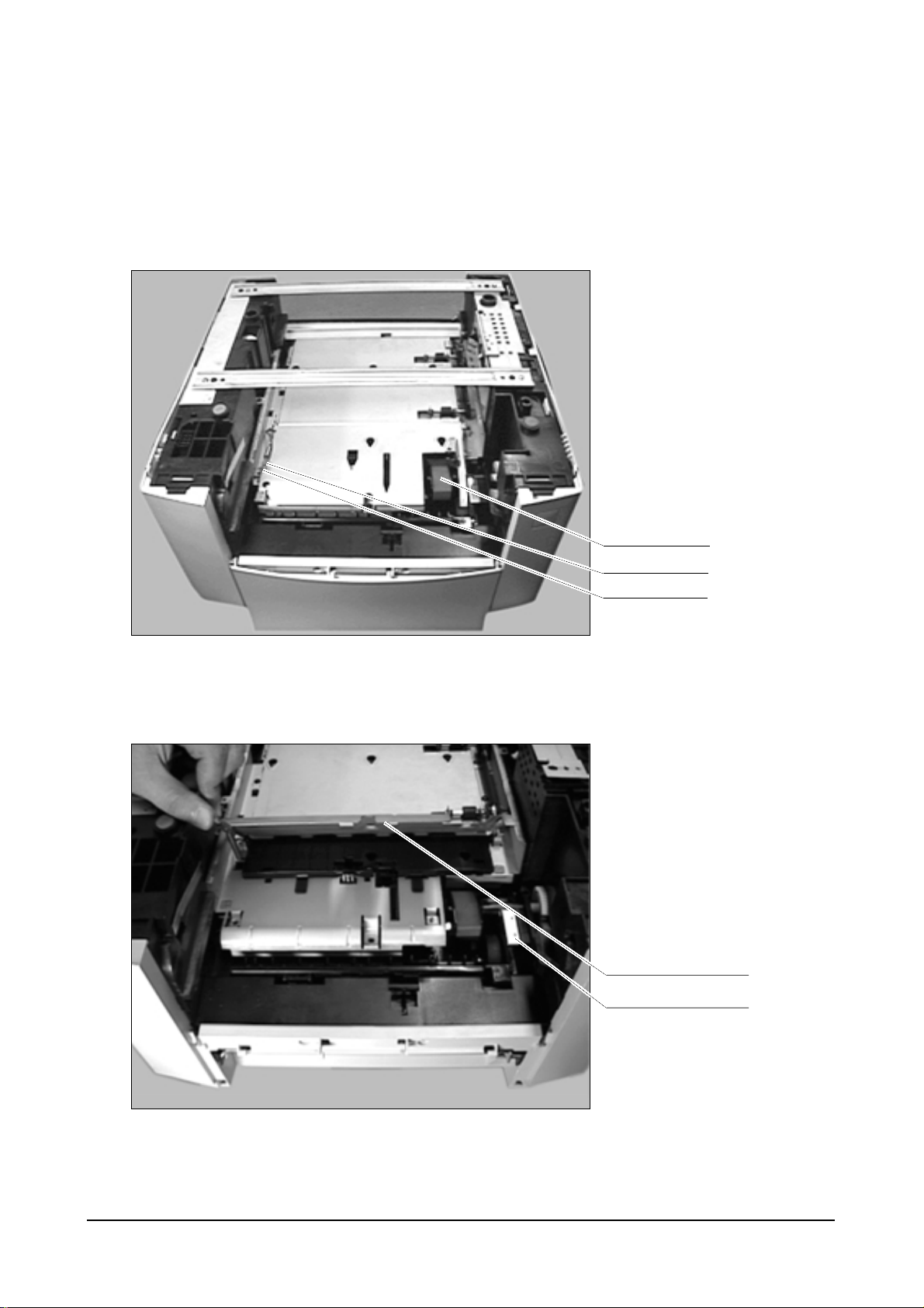
4-7 Pickup Ass’y
Disassembly
Samsung Electronics4-14
After running about more than
100,000 pages, the pickup ass’y
may be needed to be replaced
depending on feeding quality.
Remove the screw of Bracket
Support and tension spring.
Lift Guide Front Duplex and
remove the 3 mounting screws of
Pickup Ass’y.
Pickup Ass’y
Tension Spring
Guide Front Duplex
Screws
Screw
 Loading...