

SAMSUNG ML-7300 Service Manual
ML-7300 Series
LASER PRINTER CONTENTS
SERVICE
Manual
1. Precautions
2. Reference Information
3. Product Information
4. Disassembly
5. Trouble Shooting
6. Exploded Views & Parts List
7. Electrical Parts List
8. Block Diagrams
9. PCB Diagrams
10. Port Thru
(Network Printer Card)
11. schematic diagrams
Download Service Manual And Resetter Printer at http://printer1.blogspot.com
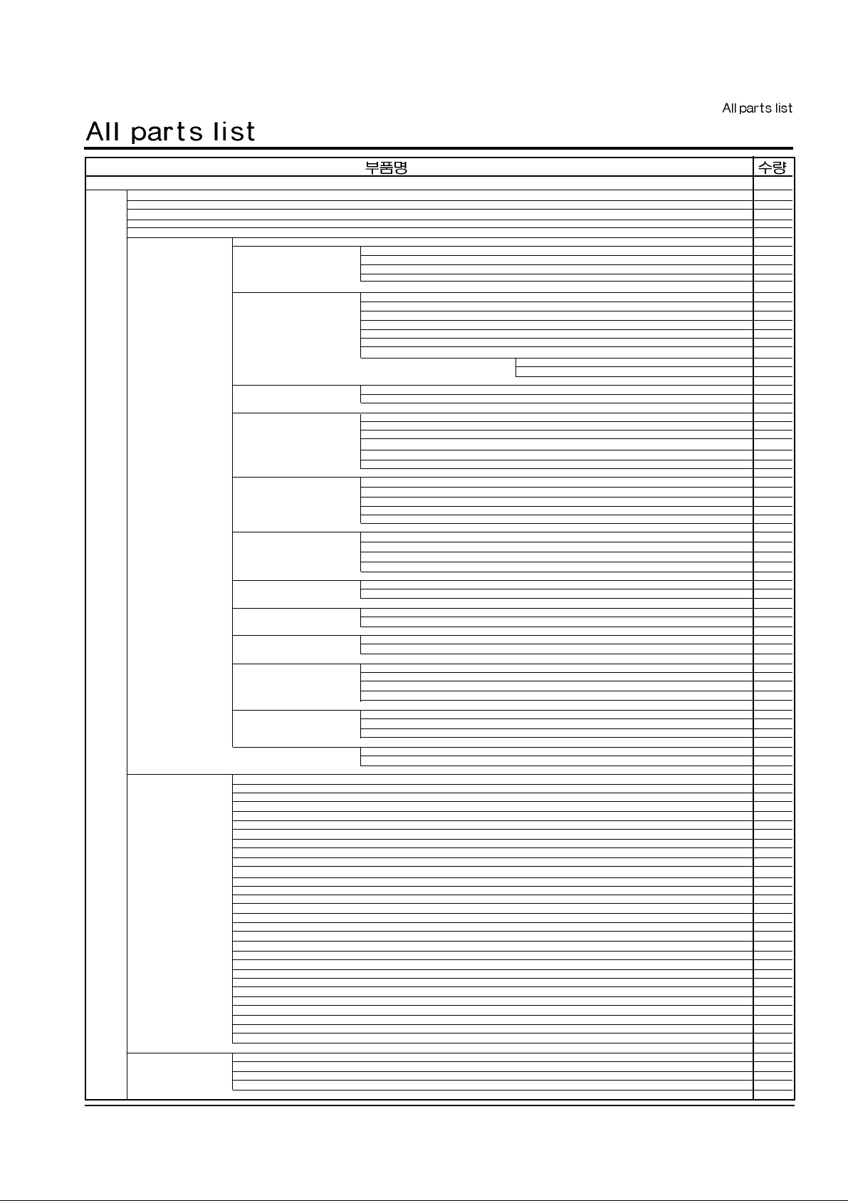
ML-7300N
CORE-FERRITE 1
UNIT-LSU 1
MAN(CARD)- QRG CARD 1
BOX-MAIN 1
ELA HOU-FRE BASE OUT 1
ELA HOU-CST SENSER 1
SCREW-MACHINE 2
IPR-BRKT PAPER SIZE 1
IPR-PUSH PLT SPRING 1
PBA SUB-CASSETTE 1
ELA UNIT-B/K C/O(KME) 1
SCREW-MACHINE 2
CABLE TIE 1
CBF HARNESS-COVER ASS’Y 1
SPRING-C/O 1
SPRING-C/O COM 1
PMO-ACTUATOR C/O 1
MEA RACK-BRKT C/O 1
IPR-BRKT C/O 1
IPR-GROUND BRKT C/O 1
ELA UNIT-PTL 1
PMO-COVER QUENCHING 1
PBA SUB-PTL 1
ELA UNIT-FUSER TERMINAL 1
SCREW-ASS’Y MACH 2
NUT-HEXAGON 2
CABLE TIE 1
CBF HARNESS-FUSING 1
IPR-TERMINAL FU 2
PMO-HOUSING TERMINAL 1
MEA RACK-GUIDE T/R 1
CABLE CLAMP 1
IPR-PLATE SAW 1
PPR-INSULATOR G/TR 1
PMO-GUIDE TRANSFER 1
PMO-HOLDER SAW 1
MEA RACK-EXIT ROLLER 4
SPRING-EXIT ROLL FD 1
PMO-HOLDER EXIT ROLL 1
PMO-ROLLER FD F 1
PMO-ROLLER FD R 1
MEA RACK-TERMINAL HV 1
SPRING-CS 3
ICT-TERMINAL HV 3
MEA UNIT-GUIDE DEVE:L 1
“SPRING-PS,G/DEV” 1
PMO-GUIDE DEV L 1
MEA UNIT-GUIDE DEVE:R 1
“SPRING-PS,G/DEV” 1
PMO-GUIDE DEV R 1
MEA UNIT-HOLDER TR:R 1
SPRING-PLATE TR 1
SPRING-TR_R 1
PMO-BUSH 1
PMO-HOLDER TR R 1
MEA UNIT-HOLDER TR:L 1
SPRING-TR_L 1
PMO-BUSH 1
PMO-HOLDER TR L 1
MEA UNIT-GUIDE P/UPPER 1
IPR-GUIDE P/UPPER 1
UNIT/AGITATOR-BRUSH G/P 1
ELA HOU-MP TRAY 1
PHOTO-INTERRUPTER 1
SCREW-TAPTITE 1
SCREW-TAPTITE 1
SCREW-TAPTITE 2
RING-E 1
SOLENOID-MP 1
CBF HARNESS-MP 1
SPRING-C/O COM 1
SPRING-KNOCK UP MP 1
SPRING-F/P MP 1
BEARING-PICK UP 2
GEAR-CAM 1
IPR-K/UP PLATE MP 1
IPR-BKT SOLENOID MP 1
ICT-SHAFT PICK UP MP 1
PMO-FRAME MP 1
PMO-BUSHING K/UP MP 1
PMO-IDLE PICK UP MP 2
PMO-HOUSING P/UP MP 1
PMO-LIMIT SOLENOID 1
PMO-HOLDER PAD MP 1
PMO-BKT HOLDER MP 1
PMO-ACTUATOR EMPTY 1
PMO-SUB GUIDE MP 1
PMO-GUIDE RING 1
PMO-ACTUATOR PAPER 1
RPR-PAD KNOCK UP MP 1
RPR-RUBBER P/UP MP 1
RPR-FRICTION PAD MP 1
ELA HOU-BRKT DUPLEX 1
SCREW-TAPTITE 1
SCREW-TAPTITE 2
RING-CS 3
RING-E 3
Samsung Electronics
I
Download Service Manual And Resetter Printer at http://printer1.blogspot.com
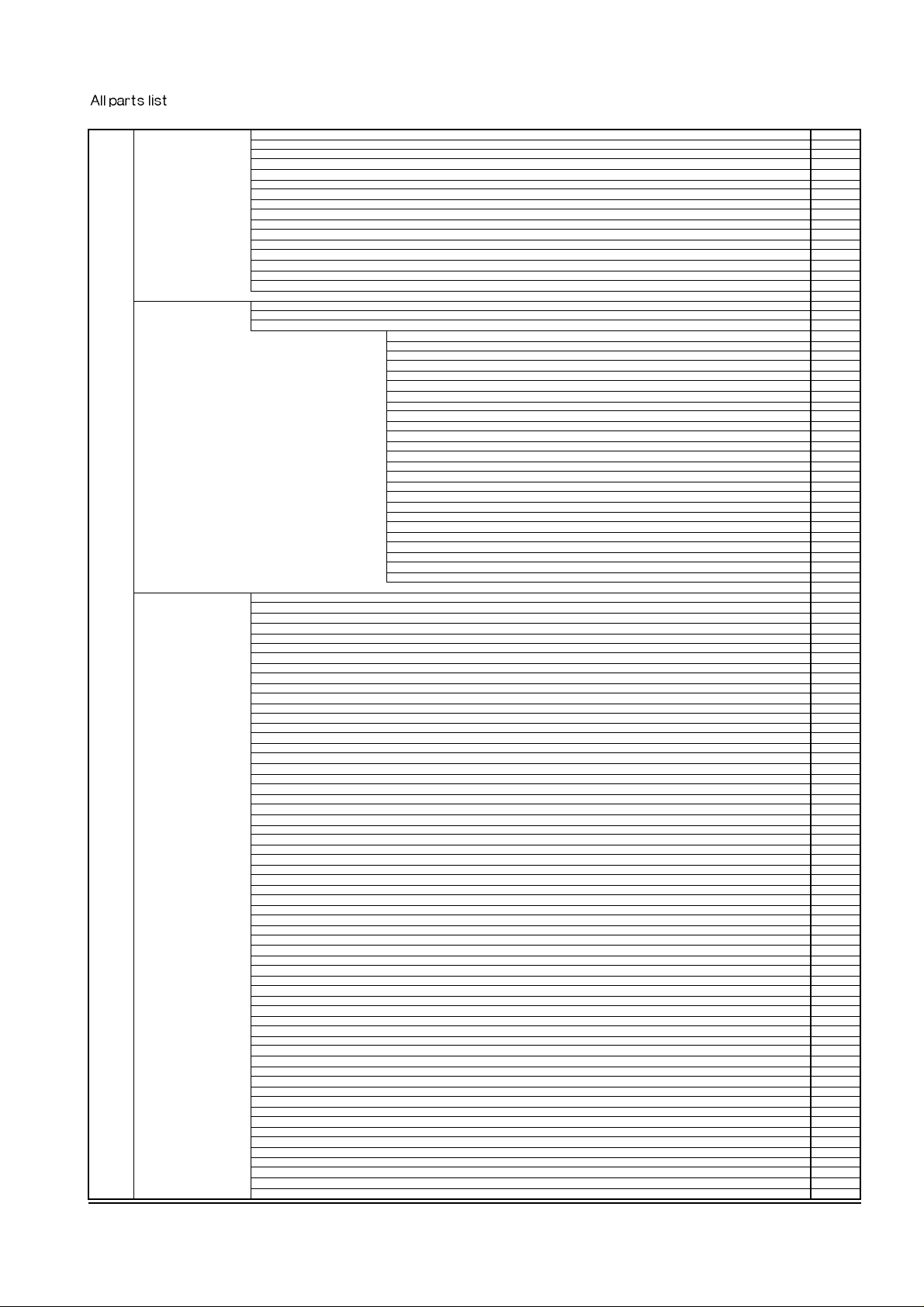
SOLENOID-DUPLEX 1
SPRING-SOLENOID DP 1
SPRING-PLATE K/UP 1
BELT-TIMMING 1
“GEAR-EXIT/U,ID” 1
“GEAR-DP,IDLE” 2
GEAR-DUPLEX 2
IPR-BRKT DUPLEX 1
IPR-LINK DUPLEX 1
ICT-SHAFT BELT 1
ICT-SHAFT BELT2 1
ICT-SHAFT SWING 1
PMO-BRKT GEAR LOWER 1
PMO-BEARING LARGE DP 4
“PMO-BEARING SMALL,DP” 2
PMO-PULLEY DUPLEX 2
ELA HOU-ENGINE_7300 1
PPR-INSULATOR PCU 1
PBA MAIN-ENGINE_7300 1
MEA UNIT-SHIELD PCU 1
SCREW-TAPTITE 2
SCREW-TAPTITE 4
SCREW-TAPTITE 2
SCREW-TAPTITE 3
CBF HARNESS-DUPLEX GND 1
SPRING-FRONT DP 1
BELT-TIMMING 1
GEAR-DUPLEX 1
IPR-BRKT SUPPORTER 1
IPR-GUIDE DUPLEX 1
IPR-GUIDE FRONT DP 1
IPR-SHIELD PCB 1
IPR-SPRING UPPER DP 2
IPR-BRKT IDLE ROLLER 1
IPR-SHEET FRONT DP 1
PMO-ACTATOR FRONT DP 1
PMO-GUIDE UPPER DP 1
“PMO-LEVER-OPEN,DP” 1
PMO-BEARING LARGE DP 4
PMO-PULLEY DUPLEX 2
PMO-ROLLER UPPER DP 2
PMO-ACTUATOR EMPTY 1
PMO-IDLE ROLLER 1
RPR-CUSHION GUIDE 1
RCT-ROLLER LOWER DP 2
ELA HOU-FRAME BASE IN 1
PHOTO-INTERRUPTER 1
FAN-DC 1
SCREW-MACHINE 1
SCREW-MACHINE 2
SCREW-TAPTITE 4
SCREW-TAPTITE 2
SCREW-TAPTITE 2
SCREW-TAPTITE 8
SCREW-TAPTITE 1
SCREW-TAPTITE 4
SCREW-TAPTITE 2
SCREW-TAPTITE 1
SCREW-TAPTITE 7
SCREW-TAPTITE 4
SCREW-TAPTITE 3
SCREW-TAPTITE 1
SCREW-TAPTITE 4
SCREW-TAPTITE 1
SCREW-TAPTITE 3
SCREW-TAPTITE 3
SCREW-TAPTITE 1
SCREW-TAPTITE 4
SCREW-TAPTITE 2
SCREW-TAPTITE 2
SCREW-TAPTITE 2
SCREW-TAPTITE 1
SCREW-TAPTITE 1
SCREW-TAPTITE 1
SCREW-TAPTITE 1
SCREW-TAPTITE 1
SCREW-TAPTITE 1
SCREW-TAPTITE 2
SCREW-TAPTITE 1
SCREW-TAPTITE 2
SCREW-TAPTITE 1
SCREW-TAPTITE 1
SCREW-TAPTITE 2
SCREW-TAPTITE 2
SCREW-TAPTITE 4
SCREW-TAPTITE 2
SCREW-TAPTITE 3
SCREW-TAPTITE 2
SCREW-TAPTITE 5
SCREW-TAPTITE 1
SCREW-TAPTITE 2
RING-CS 8
CABLE TIE 2
CABLE TIE 1
CABLE CLAMP 2
SPRING-CLUTCH 2
CBF-HARNESS-LSU(18P) 1
CBF HARNESS-DUPLEX GND 1
CBF HARNESS-BRUSH GND 1
CBF HARNESS-JOINT+ENGINE 1
CBF HARNESS-EMI WIRE 1
CBF HARNESS-CASSETTE 1
CBF HARNESS-SCF1 1
CBF HARNESS-VIDEO 1
CBF HARNESS-SMPS 1
Samsung ElectronicsII
Download Service Manual And Resetter Printer at http://printer1.blogspot.com
CBF HARNESS-MP GND 1
CBF HARNESS-JOINT 1
SPRING-G_FRONT 1
FOOT-RUBBER 2
BEARING-E/UP R 1
GEAR-EXIT 1
“GEAR-EXIT/U,ID” 4
GEAR-P/UP DRIVE 2
“GEAR-DP,IDLE” 1
“GEAR-EXIT,IDLE(Z17)” 1
ICT-BRKT SUPPORTER2 1
IPR-GROUND ICU 1
IPR-GROUND BOTTOM 1
IPR-FRAME ICU 1
IPR-PLATE CST GUIDE 1
IPR-SHIELD ICU 1
IPR-GROUND BRKT GEAR 1
IPR-GROUND FUSER 1
IPR-GROUND OPC 1
IPR-TERMINAL T/R 1
IPR-BRKT DUST 1
IPR-COVER PCB 1
IPR-GROUND DU BRKT 1
IPR-GROUND EXIT ROLL 1
IPR-BAR CROSS BOTTOM 2
IPR-GUIDE P/FRONT 1
IPR-GND SHIELD SMPS 1
IPR-GROUND MP CON 1
IPR-GND BAR BOTTOM 1
IPR-GROUND FUSER R 1
IPR-PLATE GRIP CST 1
ICT-SPACER FRAME 1
PMO-ACTATOR REAR DP 1
PMO-FRAME BASE 1
PMO-ACTUATOR FEED 1
PMO-CAP WIRE 1
PMO-CAP ACT FEED 1
PMO-CAP WIRE CST 1
PMO-CAP TERMINAL TR 1
PMO-HINGE GUIDE R 1
PMO-STRIPE 1
PMO-GUIDE EXIT FD 1
PMO-HOLDER-G/PAPER 1
PMO-CLEANER LSU 1
PMO-CAP WIRE LSU 1
PMO-LEVER STACKING 1
PMO-LEVER SEESAW 1
PMO-LEVER STACKING 2 1
PMO-REAR CST ALIGN 2
RCT-ROLLER EXIT FD 1
“MEC-BEARING,EXIT” 1
MEC-BRUSH 1
ELA HOU-SOCKET CON 1
SPRING-TONER SENSOR 3
PMO-HOLDER_LOWER 1
PMO-HOLDER_UPPER 1
MEA RACK-ROLLER TR 1
RING-E 1
GEAR-TRANSFER 1
MEC-ROLLER TRANSFER 1
CABLE CLAMP 1
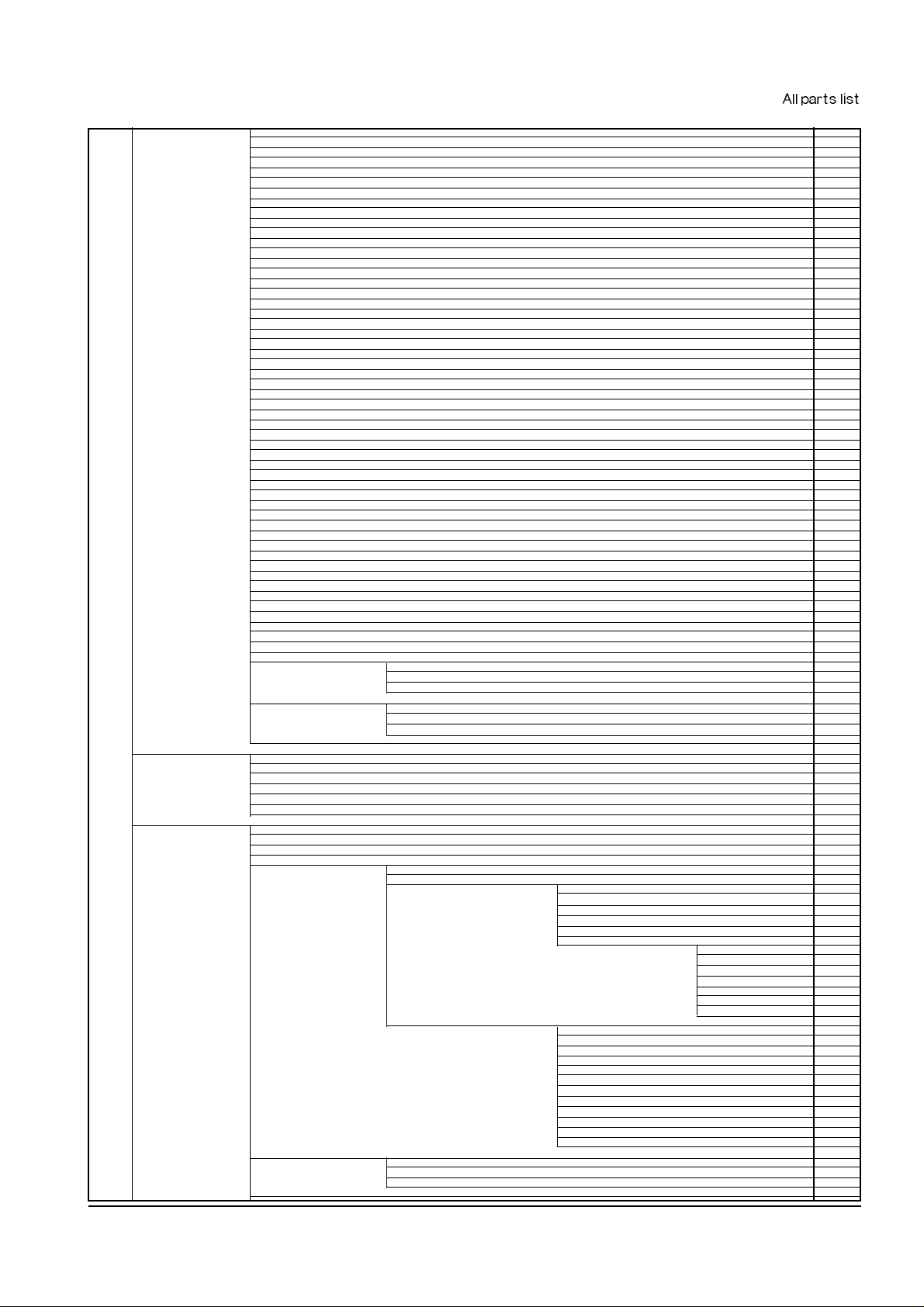
ELA HOU-SMPS 1
SMPS 1
SPRING-LINK WIRE 1
HEAT SINK-SMPS 1
IPR-SHIELD SMPS 1
PMO-CAP POWER 1
PMO-CAP WIRE SUPPORT 1
ELA HOU-COVER MAIN 1
PMO-COVER-RIGHT 1
PMO-COVER EXIT 1
PMO-LINK TRAY 2
ELA HOU-COVER HOUSING 1
SCREW-TAPTITE 6
ELA HOU-COVER TOP 1
SCREW-TAPTITE 2
SCREW-TAPTITE 1
IPR-SPRING HINGE 2
PMO-COVER TOP 1
PMO-STOPPER HINGE 1
MEA RACK-COVER OPEN 1
SPRING-CS 1
SPRING-HOOK LEVER2 1
LABEL(P)-LSU CLEAN 1
PMO-COVER OPEN 1
PMO-BUTTON-OPEN 1
PMO-HOOK OPEN 1
PMO-STACKER 1
ELA UNIT-PNL&LCD 1
SCREW-TAPTITE 1
SPRING-LCD LOCKER 1
IPR-INSULATOR PANEL 1
PMO-HOUSING PANELU 1
PMO-HOUSING-PANEL.L 1
PMO-KEY-SEESAW 1
PMO-WINDOW PANEL 1
PMO-KEY ONLINE 1
PMO-LCD LOCKER 1
PBA SUB DISP-PANEL 1
PBA SUB DISP-LCD 1
PBA SUB DISP-PNL&LCD 1
MEA UNIT-COVER FRONT 1
SPRING-CS 1
PMO-COVER-FRONT 1
PMO-BUTTON-POWER 1
MEA UNIT-COVER LEFT 1
Samsung Electronics
III
Download Service Manual And Resetter Printer at http://printer1.blogspot.com
PMO-COVER-LEFT 1
PMO-AIRDUCT 1
MEA UNIT-RACK COVER REAR 1
SCREW-TAPTITE 3
SPRING-FEED RLL 3
SPRING-REAR 2
GEAR-DUPLEX 1
ICT-BRKT REAR COVER 1
IPR-SPRING UPPER DP 1
PMO-COVER-REAR 1
PMO-BEARING LARGE DP 2
PMO-ROLLER UPPER DP 1
PMO-GUIDE INNER DP 1
PMO-IDLE PICK UP 3
RCT-ROLLER REAR DP 1
MEA UNIT-COVER TRAY 1
PMO-COVER-TRAY 1
PMO-COVER COLOR 1
PMO-SUBTRAY-FIRST 1
PMO-SUBTRAY-SECOND 1
MEA UNIT-TRAYMP 1
ICT-SHEET SIDE GUIDE 1
PMO-SIDE GUIDE TRAY 1
PMO-TRAY-MP 1
ELA HOU-BRKT MOTOR 1
GREASE-BEARING 0.001
MOTOR-STEP 1
SCREW-MACHINE 3
SCREW-MACHINE 2
WASHER-PLAIN 2
WASHER-PLAIN 1
RING-E 1
GEAR-118/23 1
GEAR-RDCN OPC 1
GEAR-IDLE 97 1
GEAR-IDLE FU 1
GEAR-OPC DRV2 1
GEAR-FUSER DRIVE 1
GEAR-OPC DRIVE(12) 1
GEAR-FEED DRIVE 1
IPR-BRACKET MOTOR J 1
IPR-BRACKET(MOTOR 21) 1
ELA HOU-DEVE UNIT(E) 1
ELA HOU-CONTROLLER(N) 1
PBA ETC-POSTSCRIPT 1
PBA MAIN-CONTROLLER 1
ELA HOU-ABZO 1
SCREW-MACHINE 2
CAP-BRKT NET OPT 1
PBA SUB-NPC(NEC) 1
MEA ETC-CONTROLLER BRKT(N) 1
SCREW-TAPTITE 3
IPR-BKT SERIAL 1
MEC-BRKT ICU & GASKET 1
IPR-BRKT ICU(B) 1
RPR-GASKET ICU(10) 1
RPR-GASKET ICU(20) 1
RPR-GASKET ICU(90) 1
ELA HOU-FUSER ASS’Y 1
LAMP-HALOGEN 1
SCREW-TAPTITE 2
SPRING-RAIL 2
ELA HOU-COV FU UPPER 1
THERMOSTAT 1
SCREW-TAPTITE 1
SCREW-TAPTITE 1
SCREW-TAPTITE 2
IPR-ELECTRODE FU R 1
IPR-ELECTRODE FU/L 1
IPR-ELECTRODE M 1
PMO-COVER FUSER UP 1
PMO-CAP TERMINAL 1
ELA HOU-FRAME FUSER 1
THERMISTOR-NTC 1
SCREW-TAPTITE 2
SCREW-TAPTITE 2
SCREW-TAPTITE 1
SCREW-TAPTITE 3
SPRING-PR(7300) 2
BEARING-PRESSURE/R 2
BEARING-H/R L 1
BEARING-H/R R 1
GEAR-FUSER 1
IPR-FRAME FUSER 1
IPR-SPR THERMISTOR 1
PMO-GUIDE FRONT 1
PMO-RAIL FUSER L 1
PMO-RAIL FUSER R 1
RCT-ROLLER HEAT 1
MEC-ROLLER PR(7300) 1
MEA RACK-COV FU LOW 1
SPRING-SAPERATION 4
SPRING-FUSER EXIT 3
BEARING-EXIT FU L 2
BEARING-EXIT FU 2
GEAR-EXIT 2
LABEL(P)-CLEAN FELT 1
PMO-GUIDE CLAW 4
PMO-COVER FUSER LOW 1
ROLLER-EXIT 3
RCT-ROLLER EXIT FU 2
MEA RACK-BRK GEAR FU 1
RING-CS 4
“GEAR-EXIT/U,ID” 2
“GEAR-EXIT,IDLE(Z17)” 2
PCT-SHEET H/R 1
Samsung ElectronicsIV
Download Service Manual And Resetter Printer at http://printer1.blogspot.com
Samsung Electronics
V
PMO-BRKT FUSER GEAR 1
MEA RACK-GUIDE REAR 1
SPRING-ACTUATOR 1
LABEL(P)-FUSER JAM 1
LABEL(P)-HIGH TEMPER 1
PMO-REAR FUSER 1
PMO-ACTUATOR EXIT 1
MEA UNIT-FEEDER CST 1
TAPE-FILAMENT 0.1
SCREW-MACHINE 1
SCREW-TAPTITE 1
SCREW-TAPTITE 1
SCREW-TAPTITE 2
SCREW-TAPTITE 1
SCREW-TAPTITE 2
RING-E 1
SPRING-PLATE K/UP 1
SPRING-LEVER 1
SPRING-SUB PLATE 2
LABEL(R)-CST REAR 1
LABEL(R)-INSTRUCTION 1
IPR-FINGER 1
IPR-GUIDE EXT LOCK 1
IPR-GUIDE PAPER SCF 1
IPR-GUIDE PLT PAPER 2
IPR-PLATE KNOCK UP 1
IPR-PLATE SPR LOCK 1
IPR-PLATE SUB K/UP 1
IPR-SPR PLATE G/SIDE 1
ICT-SHAFT SPR K/UP 1
PMO-COVER-GUIDE EXT 1
PMO-BUSH K/UP 2
PMO-CAP PLATE K/UP 1
PMO-FRAME-CASSETTE 1
PMO-GUIDE-EXT CST 1
PMO-GUIDE-PAPER 1
PMO-GUIDE PAPER SIZE 1
PMO-GUIDE-SIDE CST 1
PMO-LINK LEVER 1
PMO-SIDE GUIDE EXT 1
PMO-SUB GUIDE-CST 1
PMO-LEVER PAPER 1
PMO-ROLLER FD R 1
PMO-WINDOW PAPER 1
PMO-LOCKER PLATE 1
RPR-PAD CST 1
“SPRING-LOCKER,PLATE” 1
MEA RACK-PICK UP 1
GREASE-BEARING 0.001
GREASE-BEARING 0.001
SCREW-TAPTITE 1
WASHER-PLAIN 5
RING-CS 1
SPRING-FEED SMALL 1
SPRING-FEED LARGE 1
BEARING-PICK UP 4
GEAR-P/UP DRIVE 1
GEAR-PICK UP 1
GEAR-FEED 1
IPR-SHAFT FEED IDLER 2
IPR-PAPER GUIDE FEED 1
IPR-GROUND FEED 1
ICT-SHAFT IDLE LARGE 1
ICT-SUB SHAFT P/UP 1
ICT-SHAFT FEED 1
ICT-SHAFT PICK UP 1
PMO-ROLLER FEED L 2
PMO-ROLLER FEED S 1
PMO-SUB HOLDER FEED 1
PMO-FRAME FEED 1
PMO-HOUSING PICK UP 1
PMO-FEED ROLL DRIVE 1
PMO-HOLDER FEED S 1
PMO-HOLDER FEED L 1
RPR-RUBBER PICK UP 1
INA-TEST 110V 1
PAPER-ART 0.02
PAPER-ART 1
PAAWOOD-LABELASS’Y(STA) 1
LABEL(P)-DUPLEX 1
LABEL(P)-ENERGY ST. 1
“LABEL(P)-CAU,LSU” 1
LABEL(P)-JAM2 1
LABEL(P)-BLANK(ML) 2
LABEL(P)-NPC_TEST_L 1
LABEL(R)-LASER 1
LABEL(R)-TR CHANGE 1
LABEL(R)-RATING 1
LABEL(R)-S/N(STA) 1
MEC-BARCODE 1
PAAWOOD-P ACKING ASS’Y 1
TAPE-OPP MASKING 1.5
TAPE-FILAMENT 0.7
“CUSHION—CUSHION SET,N” 1
CUSHION—SPACER 2
BAG-PE SET 1
CUSHION-DEV KME 2
CUSHION-DEV 1
CUSHION-CST 1
INA-ACCESSORY(XAR) 1
S/W APPLICATION-DRIVER CD 1
MAN(BOOK)-7000N3/XAR 1
MAN(BOOK)-USER MANUAL 1
LABEL(R)-CUSTOMER 1
“MAN(CARD)-WARR, STA” 1
Download Service Manual And Resetter Printer at http://printer1.blogspot.com

Contents
1. Precautions
2. Reference Information
3.Product Information
4. Disassembly
1-1 Safety precautions______________________________1-1
1-2 Laser Safety Statement __________________________1-2
2-1 Abbreviations and Acronyms
_____________________2-1
2-2. Diagnostic Control Unit
_________________________2-3
2-2-1. Abstract
________________________________2-4
2-2-2. List of code description
_____________________2-5
3-1 General Specifications ________________________3-1
3-2 Controller Specifications _______________________3-2
3-3 Electrical Specifications _______________________3-2
3-4 Environmental Condition_______________________3-3
3-5 Image Cartridge(Developer) ____________________3-3
3-6 Paper Handling Specifications __________________3-4
4-1 Front View
__________________________________
4-1
4-2 Rear View
__________________________________4-1
4-3 Cabinet Disassembly
__________________________4-2
4-3-1. Cover Right
_____________________________4-2
4-3-2. Cover Left
_____________________________4-4
4-3-3. Cover Front
____________________________4-5
4-3-4. Cover Main
____________________________4-5
4-3-5. Cover Rear
____________________________4-6
4-4 Video Controller board & Joint board
_______________4-7
4-5 Fuser Ass’y
________________________________4-9
4-6 Bracket Motor Ass y & Cover Open Switch Unit
_____4-12
4-7 Pickup Ass’y __________________________________4-14
4-8 Laser Scanner Unit_____________________________4-15
4-9 Multi Purpose Tray _____________________________4-17
4-10 Control Pane_________________________________4-20
4-11 Engine Controller Board ________________________4-22
4-12 SMPS & Bracket Duplex Ass y __________________4-26
4-13 Transfer Roller Ass’y___________________________4-28
Download Service Manual And Resetter Printer at http://printer1.blogspot.com

ii Samsung Electronics
5. Troubleshooting
6. Exploded Views
& Parts List
7. Electrical
Parts Lists
8- Bloack Diagrams
5-1 Print Quality
________________________________5-1
5-2 HVPS Output Spec _____________________________5-3
5-3 Malfunction____________________________________5-4
5-4 .Connector Pin Assignment
_________________________5-8
5-4-1. Engine Board Connector Pin Assignment
______5-8
5-4-2. Joint Board Connector Pin Assignment
_________5-9
5-4-3. S.C.F Board Connector Pin Assignment ________5-11
5-5 .Troubleshooting of Video Controller
_________________5-12
5-5-1. Troubleshooting Flow Chart __________________5-12
Power Error__________________________________5-13
System Error_________________________________5-14
Engine Error _________________________________5-15
Self Test Error________________________________5-15
Parallel Interface Error _________________________5-16
Printing Error_________________________________5-16
5-5-2. Troubleshooting Table of Video Controller Board__5-16
6-1. Main Ass’y _________________________________6-2
6-2. Cover Ass’y ________________________________6-4
6-3. Frame Ass’y________________________________6-8
6-4. Cassette Ass’y ______________________________6-12
6-5. MP Tray Ass’y ______________________________6-14
6-6. Pick Up Ass’y_______________________________6-16
6-7. Fuser Ass’y ________________________________6-18
6-8. Shield Ass’y ________________________________6-20
6-9. Bracket Duplex Ass’y_________________________6-22
6-10. Bracket Motor Ass’y_________________________6-24
6-11. Frame SCF Ass’y___________________________6-26
6-12. Cassette SCF Ass’y_________________________6-29
7-1. Main Engine PBA ___________________________7-1
7-2. Main Controller PBA ________________________7-5
7-3. FLASH MEMORY PBA _____________________7-8
7-4. PTL PBA __________________________________7-8
7-5. CASSETTE PBA ____________________________7-8
7-6. POSTSCRIPT PBA __________________________7-8
7-7. DISP-PANEL PBA ___________________________7-9
7-8. DISP-LCD PBA _____________________________7-9
7-9. TONER PBA _______________________________7-9
7-10. NETWORK CARD PBA(100BASE) _____________7-10
8-1 WIRING DIAGRAM
___________________________
8-1
8-2 Engine Controller Block Diagram___________________8-2
8-3 Video Controller Block Diagram____________________8-3
Download Service Manual And Resetter Printer at http://printer1.blogspot.com

iiiSamsung Electronics
9. PCB Diagrams
10. PortThru (Network Printer Card)
Circuit Description
1 1. Schematic Diagrams
9-1. Engine Control & Joint Board _____________________9-1
9-2. Cassette Sensor Board__________________________9-2
9-3. Video Controller Board __________________________9-3
9-4. Panel & LCD Board_____________________________9-4
9-5. PTL (Pre Transfer Lamp) Board ___________________9-5
9-6. SCF(Second Cassette Feeder) Board ______________9-6
9-7. Infrared Adapor Board __________________________9-7
9-8. Flash SIMM Board _____________________________9-8
9-9. Postscript Board _______________________________9-8
9-10. Local Talk ___________________________________9-9
9-11. Serial/IrDA Board_____________________________9-10
10-1. Introduction__________________________________10-1
10-2. Board Description _____________________________10-2
10-2-1 Configuration of Network Board_______________10-2
10-2-2 Network Board Connector Pin Assignment ______10-3
10-3 Troubleshooting of Network Card _________________10-4
10-3-1 Troubleshooting Flow Chart__________________10-4
Power Error __________________________________10-5
System Error _________________________________10-6
Network Error ________________________________10-7
PHY Chip Error _______________________________10-8
Shared Memory Interface Error___________________10-9
10-3-2 Troubleshooting Table of Network Card ________10-10
11-1 Main Circuit Diagram_________________________11-1
11-2 Engine Circuit Diagram_______________________11-13
11-3 Cassette Circuit Diagram _____________________11-19
11-4 Panel Circuit Diagram________________________11-20
11-5 PTL Circuit Diagram _________________________11-21
11-6 SCF Circuit Diagram_________________________11-22
Download Service Manual And Resetter Printer at http://printer1.blogspot.com
10. PortThru (Network Printer Card) Circuit Description
10-1. Introduction
The purpose of the Network Printer Card(PortThru) is to enable the Samsung Printer to function as a network printer.
The PortThru is a plug-in card that plugs into the Samsung Printer. The PortThru provides a Ethernet Local Area
Network interface through which the printer can be connected to the network.
ITEM Description
Novell Netware Version 3.x, 4.x, 5.0
MS Windows Windows 95/98, Windows NT(3.x, 4..x)
Support system
UNIX
AT & T System V(Rel 3.2, Rel 4.2), BSD 4.3 HP-UX(Rel 9.x, Rel 10.x)
SCO 5.x, SUN OS 5.5, SOLARIS 2.5
Macintosh APPLE
Netware IPX/SPX, Pserver, Rprint mode, NDS/Bindery
Windows IPX/SPX, TCP/IP, DLC/LLC
Support protocols UNIX TCP/IP
APPLE EtherTalk Phase 2
Network Management SNMP MIB-II, Private MIB
CPU 32bit RISC controller
Hardware Flash memory 1M byte
RAM 64 Kbyte SRAM / 8M byte DRAM
Interface with
Shared memory 64K byte SRAM
Printer
Logical connection IEEE 802.2 802.3
Attachment 10/100Base-Tx
CPU Samsung NetARM, 33MHz
PHY Chip ICS1892, 25MHz
Flash ROM 1M Byte
Memory
DRAM 8M Byte
SRAM 64K Byte
EEPROM 32K Bit
Printer Interface
NetBridge, 33MHz
60 Pin Connector
Dimension(HxWxD) 15 x 80 x 124mm
Power Consumption Max. 0.6A/ +5Vdc
Product Information
Samsung Electronics 10-1
Download Service Manual And Resetter Printer at http://printer1.blogspot.com
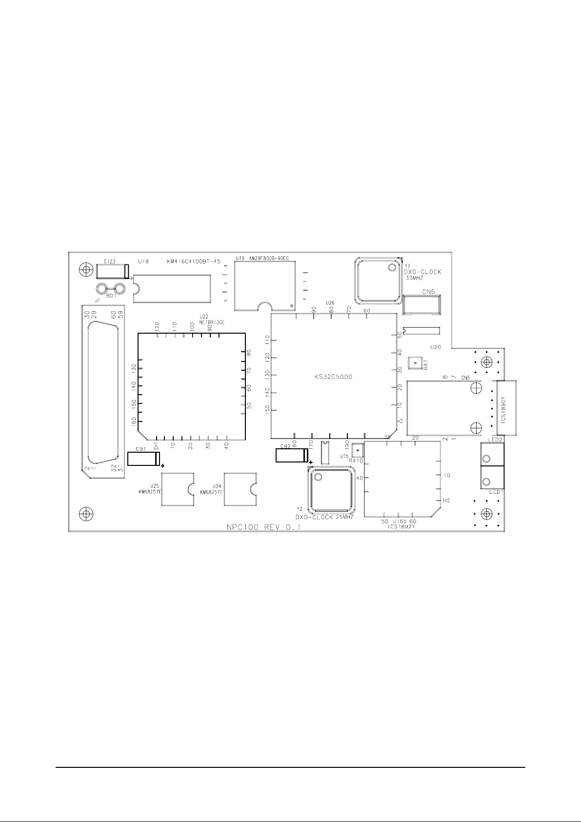
10-2. Board Description
10-2-1 Configuration of Network Board
Service Part : JC92-01119A
Product Information
Samsung Electronics10-2
Download Service Manual And Resetter Printer at http://printer1.blogspot.com
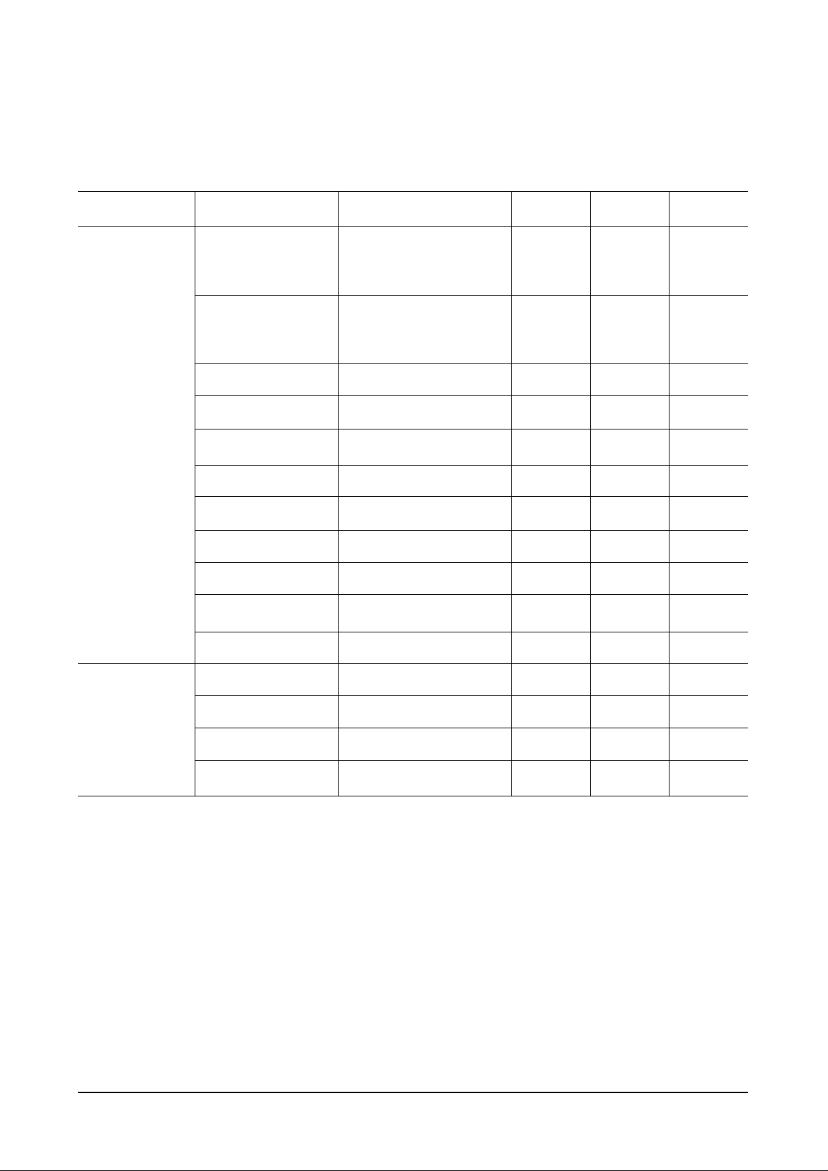
10-2-2 Network Board Connector Pin Assignment
Product Information
Samsung Electronics 10-3
Connector Description Pin No. Idle Active In/Out
21, 19, 18, 17, 37, 44,
Addr 0 ~ Addr 15 42, 40, 38, 36, 34, 32 Pulse Pulse I
30, 28, 26, 24
35, 33, 31, 29, 27, 25
Data 0 ~ 15 23, 22, 14, 13, 11, 10 Pulse Pulse I/O
9, 7, 6, 5
nPrnWait 41 +5V DGND O
PRES_L 57 DGND DGND -
nPrnlrq 15 +5V DGND O
nPrnCS 4 +5V DGND I
nPrnRE 50 +5V DGND I
nPrnWE 51 +5V DGND I
nResetIn 39 +5V DGND I
+5V 3, 58, 59, 60 +5V +5V -
DGND 8, 12, 16, 48, 52, 56 DGND DGND -
RxD 1 +5V Pulse I
TxD 2 +5V Pulse O
+5V 3 +5V +5V -
DGND 4 DGND DGND -
Printer Interface
J1
Serial Connector
CN6
Download Service Manual And Resetter Printer at http://printer1.blogspot.com
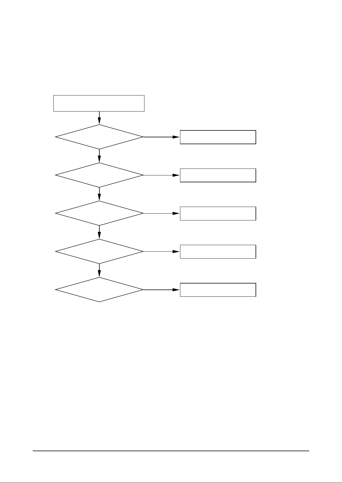
10-3 Troubleshooting of Network Card
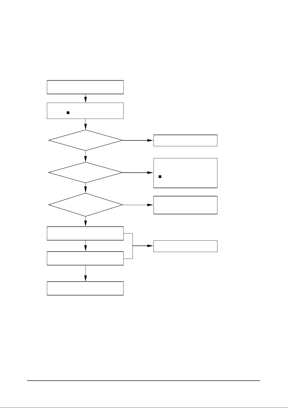
10-3-1 Troubleshooting Flow Chart
Product Information
Samsung Electronics10-4
Status LED Blinking ?
Does it light up the LEDs?
Turn off power and turn on again in
approx.5 seconds and wait 1 minute.
Go to Power Error
No
Yes
Yes
Yes
Yes
Link LED on ?
Go to System Error
No
Is it possible detecting
using syncThru from PC ?
Is it possible printing
through network ?
Go to Network Error
No
Go to PHY chip Error
No
Go to Shared Memory Interface Error
No
Download Service Manual And Resetter Printer at http://printer1.blogspot.com
Product Information
Samsung Electronics 10-5
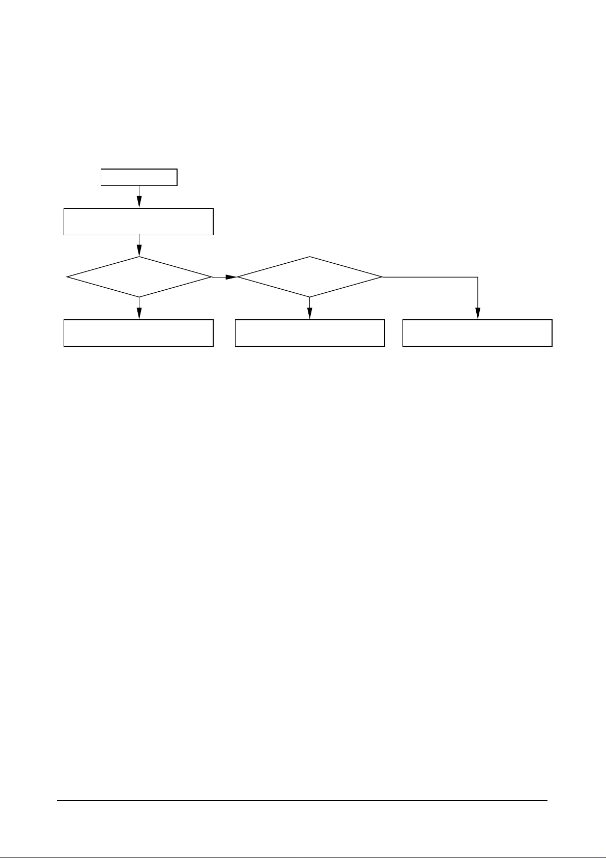
Power Error
Network board's input
voltage = +5V ?
Check the BD1 of the Network Card
Power Error
Go to System Error or Network Error
Section
Go to System Error or Network Error
Section
Replace the board
No
Is it short between
+5V and GND in the
Network board?
No
Yes
Yes
Download Service Manual And Resetter Printer at http://printer1.blogspot.com
Product Information
Samsung Electronics10-6
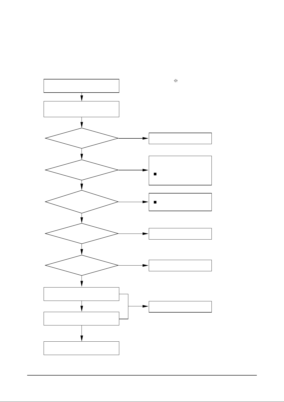
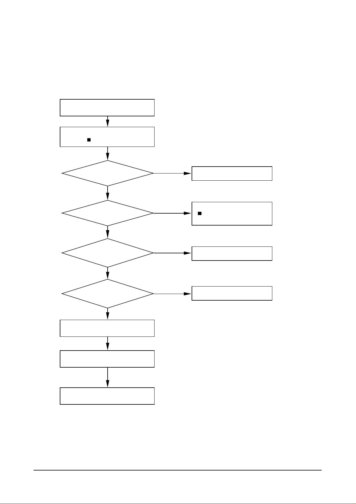
System Error
CPU's input
voltage = +5V ?
CPU's pin No. 82
Reset input level = High ?
Check the Network Board
(1) ROM installing ?
(2) Soldering status ?
Check the TMODE(pin no. 63, 64) input
level : Low
Check the EXTMREQ(pin no. 108) input
level : Low
Replace the board
If you can't repair the board
System Error
Check the filter (BD1)
No
Yes
Yes
Yes
Yes
Yes
No
U19(pin no 12)
and U165(pin no 22)'s
Reset input level = High ?
No
CPU(pin no 80)'s
input Clock = 33MHz ?
Check the Y1, R104 and R113
No
U22(pin no 63)'s
input clock = 33MHz ?
No
Check the soldering status
Check the CPU(pin no 77) and R102
Check the U22's pin no. 75
Reset signal :
Nomally High during operation
Check the connector J1's pin no. 39
Check the U22's pin no. 123
Check the U22's pin no. 75
Reset signal :
Nomally High during operation
CPU : U26
NetBridge : U22
Flash ROM : U19
DRAM : U18
PHY Chip : U165
Download Service Manual And Resetter Printer at http://printer1.blogspot.com
Product Information
Samsung Electronics 10-7
Network Error
U165's input
voltage = +5V ?
U165(pin no 82)'s
Reset input level = High ?
U165(pin no 53)'s
input Clock = 25MHz ?
Check the Network Board
Soldering status ?
Check the R79, R80, R112 and CN5
Check the LED1 and R106
Replace the board
If you can't repair the board
Network Error
Check the filter (L1, L2)
No
Yes
Yes
Yes
No
No
Check the soldering status
Check the Y2, R97 and R105
Check the connector J1's pin no. 39
Check the U22's pin no. 123
Check the U22's pin no. 75
Reset signal :
Nomally High during operation
Download Service Manual And Resetter Printer at http://printer1.blogspot.com

Product Information
Samsung Electronics10-8
PHY Chip Error
U165's input
voltage = +5V
U165(pin no. 82)'s
Reset input level = High ?
U165(pin no. 53)'s
input clock = 25MHz ?
U165(pin no. 36 and 43)'s
input clock = 2.5MHz or 25MHz ?
Check the Network Board
Solering status ?
Check the RA1, RA10, R138, R144
and R145
Check the LAN Cable
Replace the board
If you can't repair the board
PHY Chip Error
Check the filter (L1, L2)
No
Yes
Yes
Yes
Yes
No
No
Check the Y2, R97 and R105
No
Check the Y2, R97 and R105 and
check the soldering status of U165
Check the connector J1's pin no. 39
Check the U22's pin no. 123
Check the U22's pin no. 75
Reset signal :
Nomally High during operation
Download Service Manual And Resetter Printer at http://printer1.blogspot.com
Product Information
Samsung Electronics 10-9
Shared Memory Interface Error
U22's input
voltage = +5V ?
U22(pin no. 123)'s
Reset input level = High ?
U22(pin no. 63)'s
input Clock = 33MHz ?
U22(pin no. 65, 66)'s
input level = Low ?
Check the Network Board
Solering status ?
Check the R68, R69, R70, R72,
R73, R92, R127 and R128
Check the J1 connector and DRAM(U18)
Replace the board
If you can't repair the board
Shared Memory Interface Error
Check the filter (BD1)
No
Yes
Yes
Yes
Yes
No
No
Check the Y1 and R102
No
Check the soldering status of the U22
Check the connector J1's pin no. 39
Reset signal :
Nomally High during operation
Download Service Manual And Resetter Printer at http://printer1.blogspot.com
Product Information
Samsung Electronics10-10
10-3-2 Troubleshooting Table of Network Card
No. Error Type Check List Repair
Power Connection Check the BD1 of Network Card
VCC voltage (nominal is +5V) level Refer to the section of Power Error
1 VCC voltage should be in the range between Troubleshooting
+4.75 and +5.25V
Short between VCC and GND. Repair board
Reset Error : Reset signal is normalhigh during operation
System source clock is 33MHz.
Check point : Y1’s pin 5 and U26’s pin 80 Replace the Y1.
The output clock of U26 is 33MHz. Check the R102 and R122. If these two
2 The input clock of U26 is 33MHz. resistors are OK then replace the board.
Check the ROM Chip select signals
(Pin no U26-75 and U19-26)
Check the DRAM control signals(pin no U26-89, 95, 96,
99, 100 and U18-13, 14, 36, 37, 38)
Reset Error : Reset signal is normal high during operation
Check the Y2, R97 and R105.
The input clock of U165 is 25MHz. If these two resistors are OK then
3 replace the Y2
Check the R79, R80 and R112
Check the output and input signal of U165 of RJ45
connector side. Pin no. 5, 6, 10, 11 of U165.
Check the MII signals between U26 and U165
(Pin no. 30, 31, 32, 33, 34, 35, 36, 37, 38, 42, 43, 44, Refer to the section of PHY chip
4
45, 46, 47, 48, 49, 50) error
Check RA1, RA10, R138, R144 and R145.
The output clock of U26 is 33MHz. Check the R102 and R122. If these two
The input clock of U22 is 33MHz. resistor are OK then replacethe board.
5
Check the Shared Memory Cotrol signals. Refer to the Shared Memory Interface
U22-37, 38, 39 and R68, R69 and R70 Error Section.
The LEDs
does not lit
up
The status
LED does
not blinking
The status
LED is OK
but the
LINK LED
does not lit
up
The two
LEDs are
OK but can’t
detect the
Network
Printer using
SyncThru
from PC
The
SyncThru
can detect
the Network
Printer card
but Printer
does not
printing.
Download Service Manual And Resetter Printer at http://printer1.blogspot.com
Schematic Diagrams
11-1Samsung Electronics
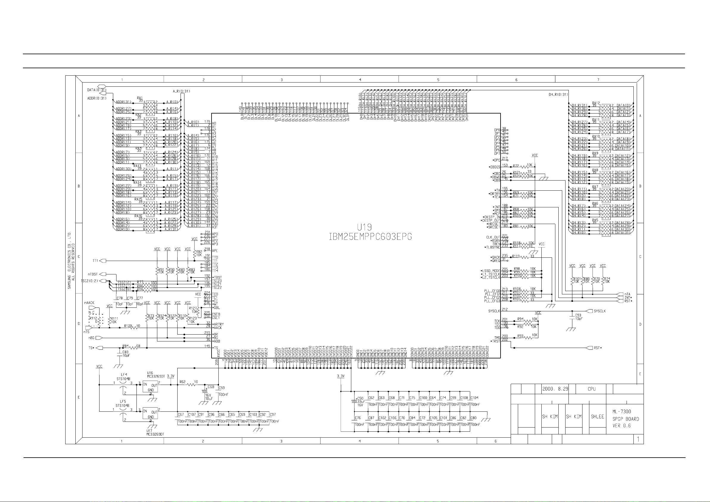
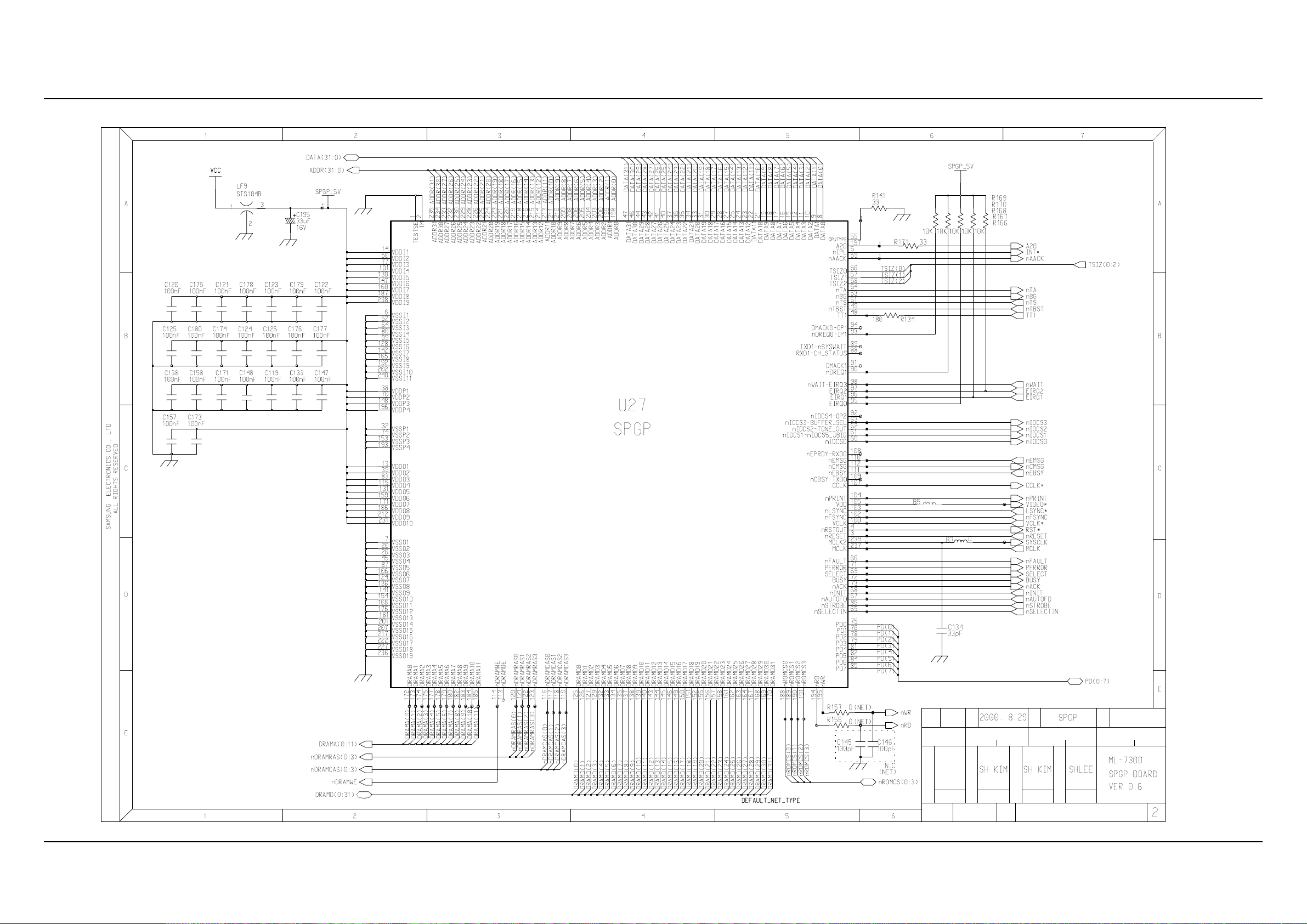
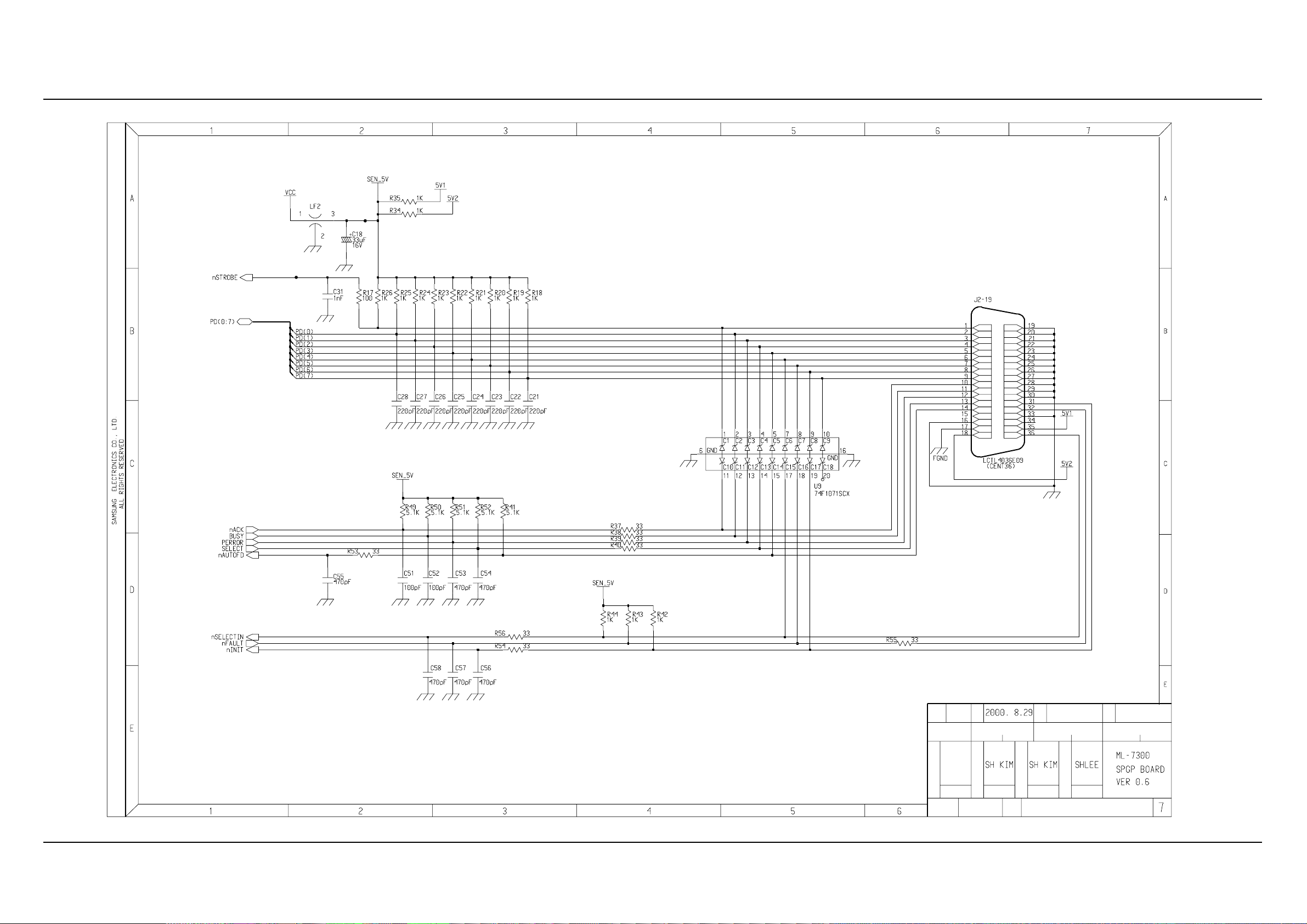
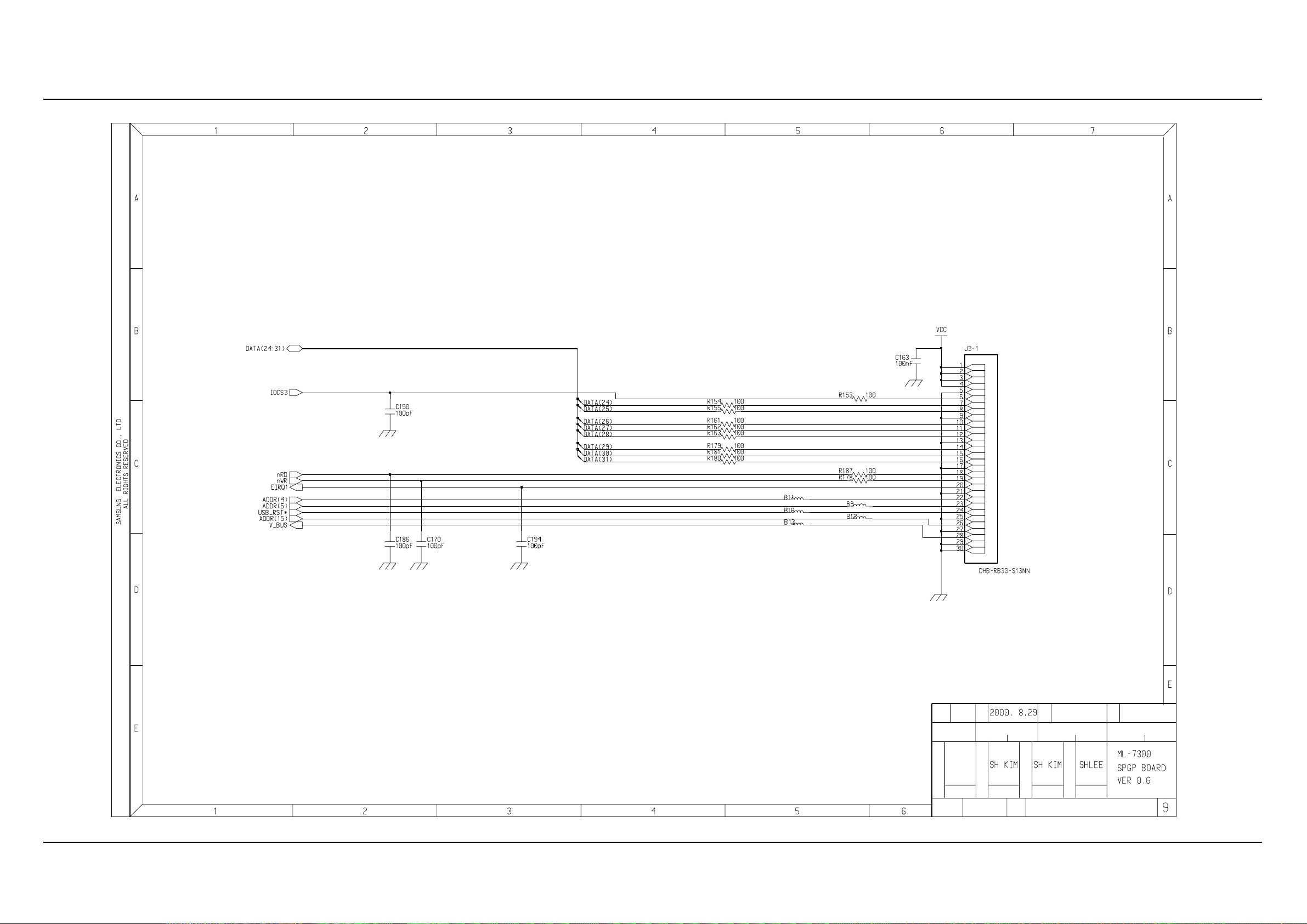
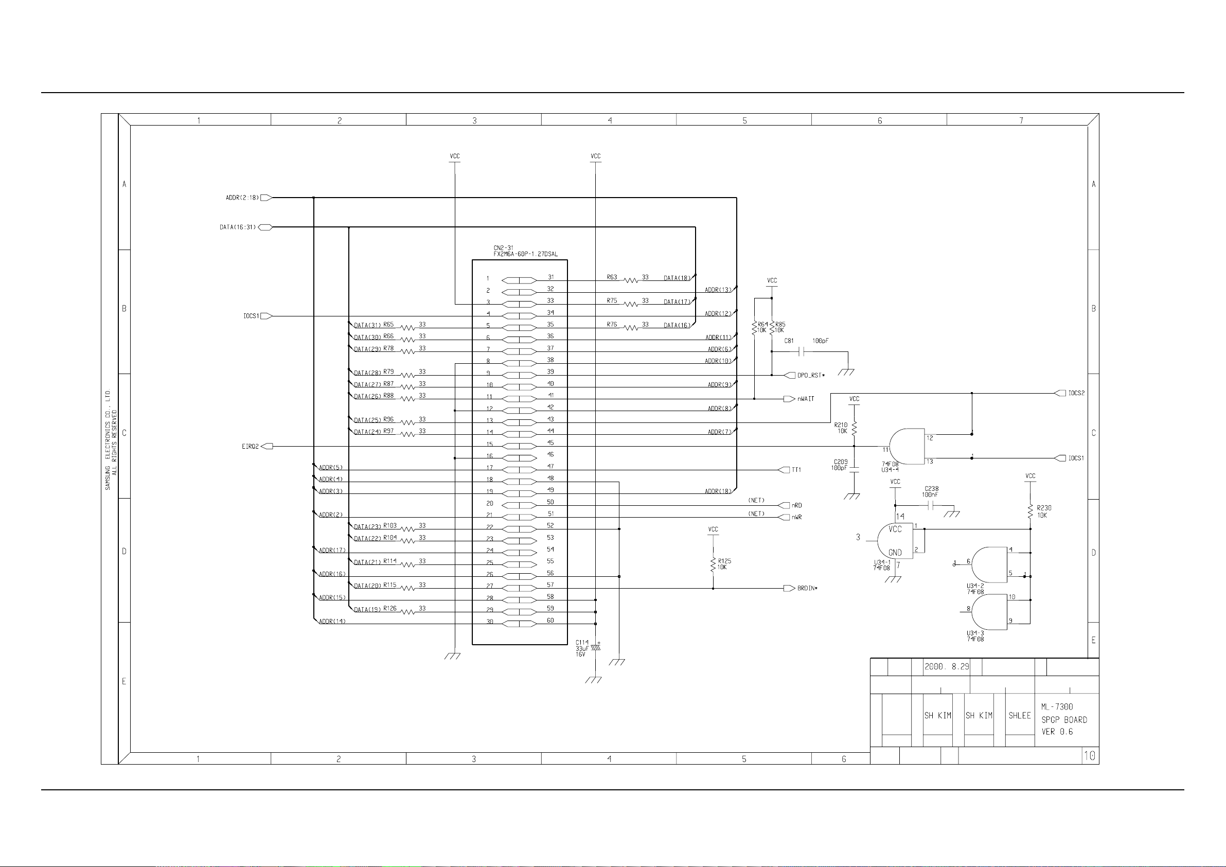
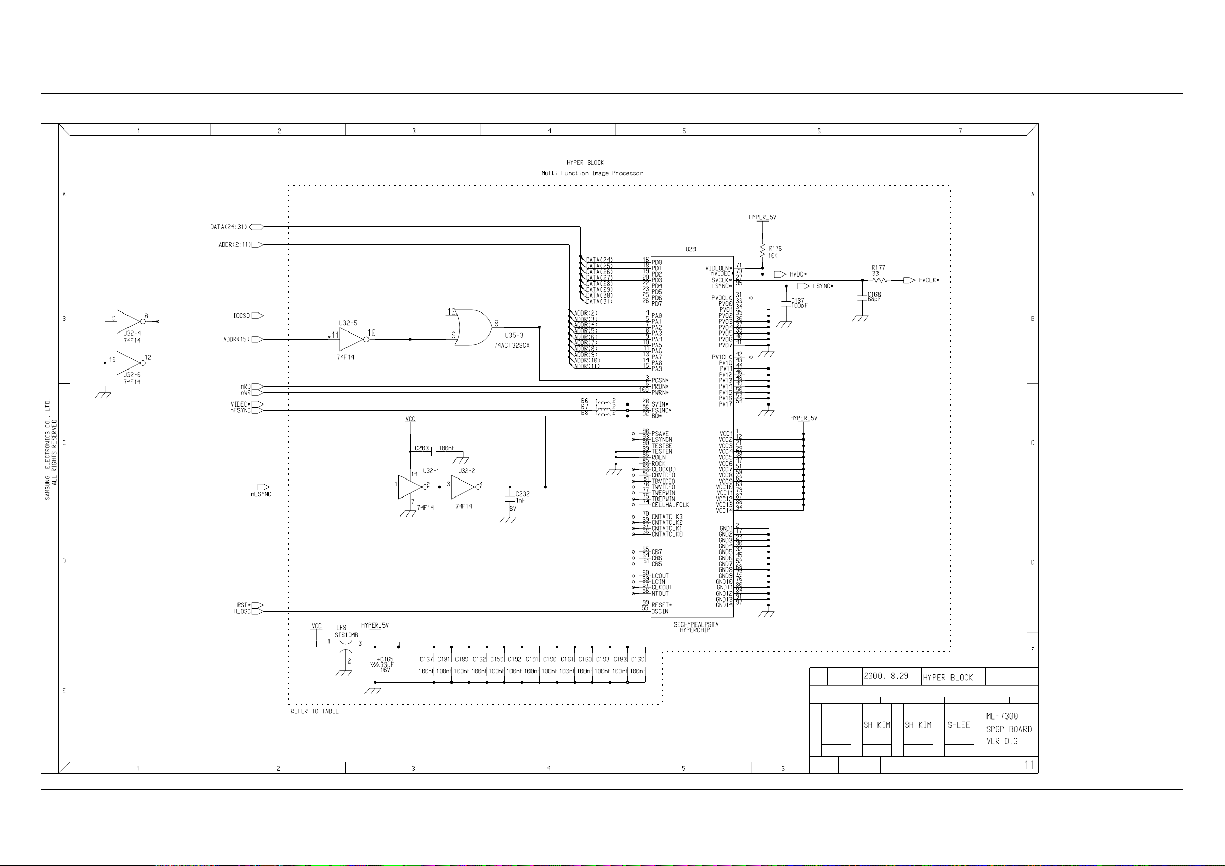
11-1 Main Circuit Diagram(1/12)
11. Schematic Diagrams
SIGN
REF NO
D
ED
P
C
E
C
N
G
R
2
E
EDIT
SEC
1
W
3
H
K
G
A
Download Service Manual And Resetter Printer at http://printer1.blogspot.com
Schematic Diagrams
11-2 Samsung Electronics
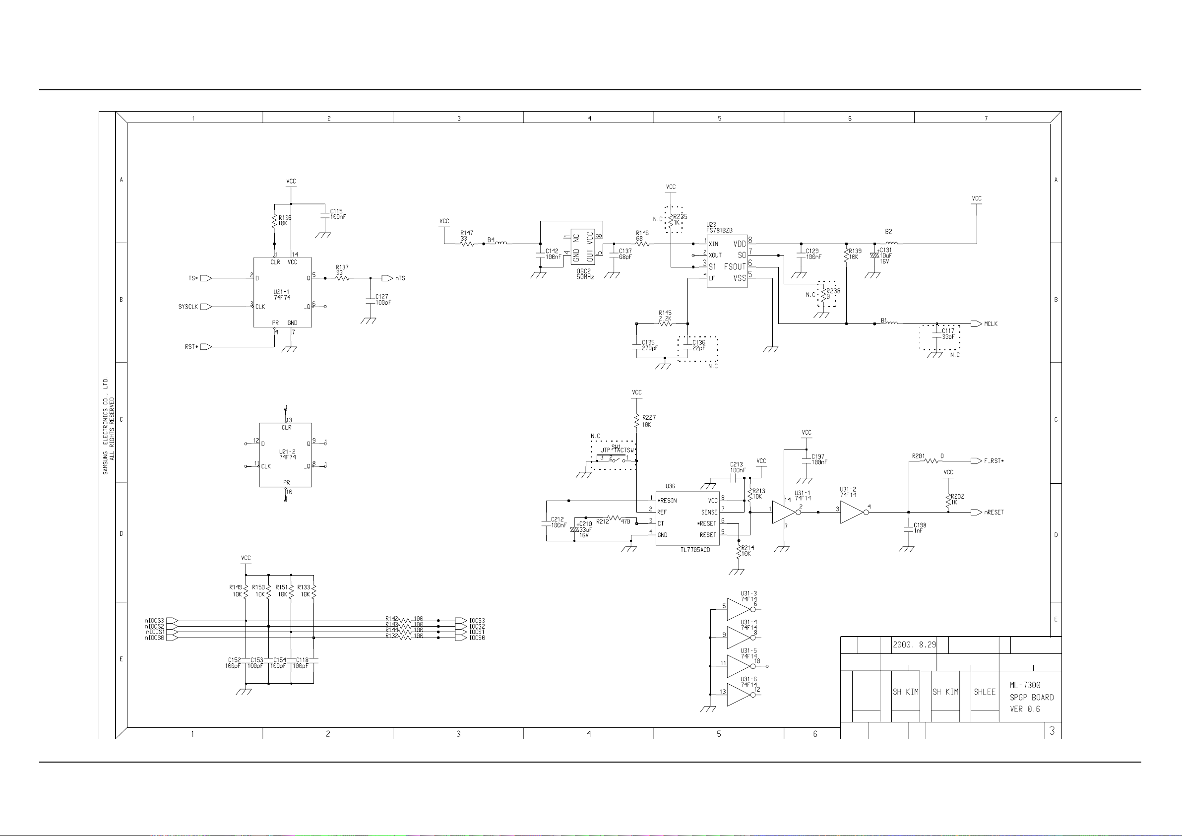
Main Circuit Diagram(2/12)
SEC
K
1
D
REF NO
G
E
C
EDIT
SIGN
ED
A
R
G
C
W
P
E
2
3
H
N
Download Service Manual And Resetter Printer at http://printer1.blogspot.com
Schematic Diagrams
11-3Samsung Electronics
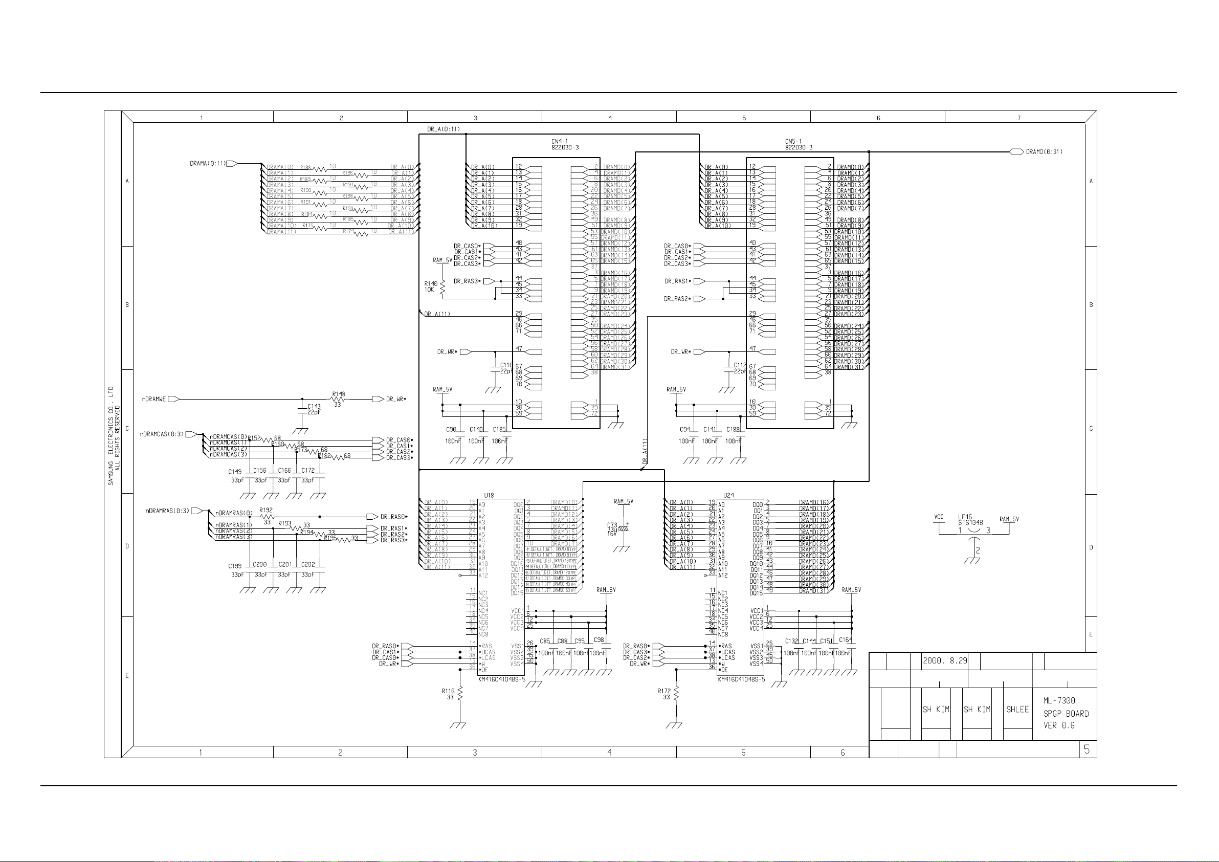
Main Circuit Diagram(3/12)
EDIT
C
E
1
SIGN
N
G
2
P
W
A
R
D
REF NO
ED
E
C
3
SEC
H
K
G
Download Service Manual And Resetter Printer at http://printer1.blogspot.com

Schematic Diagrams
11-4 Samsung Electronics
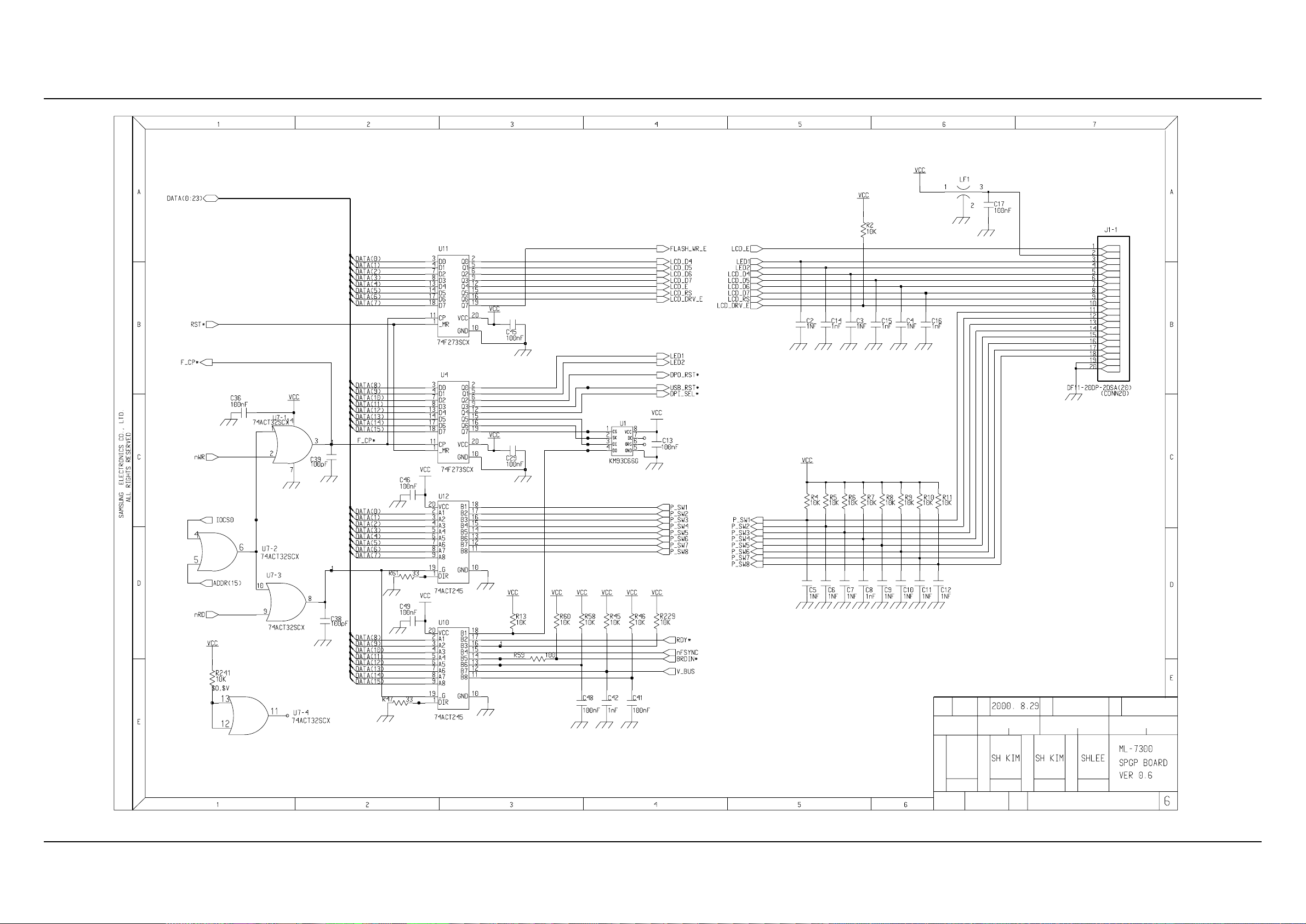
Main Circuit Diagram(4/12)
G
E
N
C
2
REF NO
1
W
A
G
3
H
R
SIGN
SEC
ED EDIT
P
C
E
D
K
Download Service Manual And Resetter Printer at http://printer1.blogspot.com
Schematic Diagrams
11-5Samsung Electronics
Main Circuit Diagram(5/12)
W
G
E
ED
REF NO
C
K
EDIT
SIGN
A
R
P
H
SEC
G
D
C
E
N
12 3
Download Service Manual And Resetter Printer at http://printer1.blogspot.com
Schematic Diagrams
11-6 Samsung Electronics
Main Circuit Diagram(6/12)
P
K
EDIT
C
R
E
G
A
W
SEC
N
G
ED
REF NO
H
C
1
SIGN
D
32
E
Download Service Manual And Resetter Printer at http://printer1.blogspot.com
Schematic Diagrams
11-7Samsung Electronics
Main Circuit Diagram(7/12)
REF NO
G
W
G
K
N
SIGN
P
EDIT 12ED 3
SEC
C
DE
HA
RE
C
Download Service Manual And Resetter Printer at http://printer1.blogspot.com

Schematic Diagrams
11-8 Samsung Electronics
Main Circuit Diagram(8/12)
P
C
ED
K
R
2 3
SECREF NO
G
N
1
C
G
E
W
E D
EDIT
SIGN
AH
Download Service Manual And Resetter Printer at http://printer1.blogspot.com
Schematic Diagrams
11-9Samsung Electronics
Main Circuit Diagram(9/12)
K
SIGN
A
R
ED EDIT
W
E
C
G
P
1
2
REF NO SEC
D
3
G
E
C
H
N
Download Service Manual And Resetter Printer at http://printer1.blogspot.com
Schematic Diagrams
11-10 Samsung Electronics
Main Circuit Diagram(10/12)
C
1
REF NO
ED
P
2
A
R
SEC
G
G
D
K
E
EDIT
SIGN
N
3
W
H
E
C
Download Service Manual And Resetter Printer at http://printer1.blogspot.com
Schematic Diagrams
11-11Samsung Electronics
Main Circuit Diagram(11/12)
N
D
H
EDITED
2
C
G
K
A
W
1
REF NO
E
SEC
R
E
P
3
G
C
SIGN
Download Service Manual And Resetter Printer at http://printer1.blogspot.com
 Loading...