

SAMSUNG ML5000AXEC Service Manual
SERVICE
LASER PRINTER
ML-5000A
Manual
LASER PRINTER CONTENTS
1. Precautions
2. Specifications
3. Disassembly and Reassembly
4. Troubleshooting
5. Exploded Views and Parts List
6. Electrical Parts List
7. Schematic Diagrams

ELECTRONICS
P/N. JC68-00015A Rev. 1.00

1. Precautions . . . . . . . . . . . . . . . . . 1-1
1-1 Safety Precautions . . . . . . . . . . . . . . . . . . . . . 1-1
1-2 Servicing Precautions . . . . . . . . . . . . . . . . . . . 1-2
1-3 ESD Precautions . . . . . . . . . . . . . . . . . . . . . . . 1-2
2. Specifications . . . . . . . . . . . . . . . 2-1
2-1 General . . . . . . . . . . . . . . . . . . . . . . . . . . . . . . .2-1
2-2 Electrical . . . . . . . . . . . . . . . . . . . . . . . . . . . . .2-2
2-3 Print Quality . . . . . . . . . . . . . . . . . . . . . . . . . .2-3
2-4 Option . . . . . . . . . . . . . . . . . . . . . . . . . . . . . . . .2-3
2-5 Paper . . . . . . . . . . . . . . . . . . . . . . . . . . . . . . . . .2-4
3. Disassembly and Reassembly . . .3-1
3-1 Removal Procedures . . . . . . . . . . . . . . . . . . . . 3-1
3-2 Face-Up Cover and Front Cover . . . . . . . . . 3-1
3-3 Panel Board and Board Cover . . . . . . . . . . . 3-3
3-4 Transfer Roller . . . . . . . . . . . . . . . . . . . . . . . . 3-3
3-5 Top Cover and Rear Cover . . . . . . . . . . . . . . 3-4
3-6 Side Covers (Left, Right) . . . . . . . . . . . . . . . . 3-4
3-7 SMPS/Engine Control Board . . . . . . . . . . . . 3-5
3-8 Control Board . . . . . . . . . . . . . . . . . . . . . . . . 3-5
3-9 Joint Board . . . . . . . . . . . . . . . . . . . . . . . . . . . 3-6
3-10 Sensor Board . . . . . . . . . . . . . . . . . . . . . . . . 3-6
3-11 Gear Bracket . . . . . . . . . . . . . . . . . . . . . . . . . 3-7
3-12 Motor . . . . . . . . . . . . . . . . . . . . . . . . . . . . . . 3-7
3-13 HVPS Board . . . . . . . . . . . . . . . . . . . . . . . . . 3-8
3-14 LSU . . . . . . . . . . . . . . . . . . . . . . . . . . . . . . . . 3-8
3-15 Fuser . . . . . . . . . . . . . . . . . . . . . . . . . . . . . . . 3-9
3-16 Upper Frame . . . . . . . . . . . . . . . . . . . . . . . 3-10
3-17 Pressure Roller . . . . . . . . . . . . . . . . . . . . . . 3-10
3-18 Pickup Roller . . . . . . . . . . . . . . . . . . . . . . . 3-11
3-19 Installing SIMM . . . . . . . . . . . . . . . . . . . . . 3-12
4. Troubleshooting . . . . . . . . . . . . . . 4-1
4-1 Abnormal Image Printing and
Defective roller . . . . . . . . . . . . . . . . . . . . . . . .4-1
4-2 Print Quality . . . . . . . . . . . . . . . . . . . . . . . . . .4-1
4-3 Malfunction . . . . . . . . . . . . . . . . . . . . . . . . . .4-12
4-4 DCU Control . . . . . . . . . . . . . . . . . . . . . . . . .4-16
5. Exploded Views and Parts List . . 5-1
5-1 Main Exploded View . . . . . . . . . . . . . . . . . . . 5-2
5-2 Main Parts List . . . . . . . . . . . . . . . . . . . . . . . . 5-3
5-3 Front Cover Exploded View . . . . . . . . . . . . . 5-4
5-4 Front Cover Parts List . . . . . . . . . . . . . . . . . . 5-5
5-5 Top Cover Exploded View . . . . . . . . . . . . . . 5-6
5-6 Top Cover Parts List . . . . . . . . . . . . . . . . . . . 5-7
5-7 Fuser Exploded View . . . . . . . . . . . . . . . . . . 5-8
5-8 Fuser Parts List . . . . . . . . . . . . . . . . . . . . . . . 5-9
5-9 Frame Exploded View . . . . . . . . . . . . . . . . . 5-10
5-10 Frame Parts List . . . . . . . . . . . . . . . . . . . . . 5-11
5-11 Feeder (1/2) Exploded View . . . . . . . . . . . 5-12
5-12 Feeder (1/2) Parts List . . . . . . . . . . . . . . . 5-13
5-13 Feeder (2/2) Exploded View . . . . . . . . . . 5-14
5-14 Feeder (2/2) Parts List . . . . . . . . . . . . . . . . 5-15
5-15 Motor Exploded View . . . . . . . . . . . . . . . . 5-16
5-16 Motor Parts List . . . . . . . . . . . . . . . . . . . . . 5-17
5-17 PCB Exploded View . . . . . . . . . . . . . . . . . . 5-18
5-18 PCB Parts List . . . . . . . . . . . . . . . . . . . . . . 5-19
6. Electrical Parts List . . . . . . . . . . . .6-1
6-1 Controller (ML-5000A) . . . . . . . . . . . . . . . . . .6-1
6-2 Engine (220V) . . . . . . . . . . . . . . . . . . . . . . . . . .6-4
6-3 Engine (110V) . . . . . . . . . . . . . . . . . . . . . . . . . .6-7
6-4 Joint . . . . . . . . . . . . . . . . . . . . . . . . . . . . . . . . .6-10
6-5 Panel . . . . . . . . . . . . . . . . . . . . . . . . . . . . . . . .6-11
6-6 Paper Empty . . . . . . . . . . . . . . . . . . . . . . . . .6-12
6-7 Sensor . . . . . . . . . . . . . . . . . . . . . . . . . . . . . .6-13
7. Schematic Diagrams
7-1 Controller (ML-5000A) 1/7
Controller (ML-5000A) 2/7
Controller (ML-5000A) 3/7
Controller (ML-5000A) 4/7
Controller (ML-5000A) 5/7
Controller (ML-5000A) 6/7
Controller (ML-5000A) 7/7
7-2 Controller (ML-5000G) 1/2
Controller (ML-5000G) 2/2
7-3 OPE Panel (ML-5000A/G)
7-4 Engine (ML-5000A/G) 1/3
Engine (ML-5000A/G) 2/3
Engine (ML-5000A/G) 3/3
7-5 Joint Board (ML-5000A/G)
7-6 HVPS (ML-5000A/G) 1/3
HVPS (ML-5000A/G) 2/3
HVPS (ML-5000A/G) 3/3
7-7 Sensor (ML-5000A/G)
7-8 Switch (ML-5000A/G)
7-9 PTL (ML-5000A/G)
Contents

Samsung Electronics 1-1
1. Precautions
1-1 Safety Precautions
Read each caution carefully:
1. Do not use this printer near water or when
exposed to inclement weather.
2. Do not place this printer on an unstable cart, stand
or table; the product may fall, causing serious
damage to the product.
3. Slots and openings in the cabinet are provided for
ventilation. To ensure reliable operation and to
protect the printer from everheating, do not block
or cover any of these openings. Do not place the
printer in an enclosure unless the enclosure
provides adequate ventilation.
4. Never push objects of any kind into the printer
through the cabinet ventilation slots as they may
touch dangerous high voltage points, create short
circuits, cause a fire, or produce an electrical shock.
Never spill liquid of any kind on the printer.
5. Do not place the printer in a location where
someone may trip on the cords.
6. Select a work surface that is large enough to hold
the printer.
7. Position the printer within six feet of the computer
and within five feet of an electrical outlet.
8. Operate this printer using the power source (110V,
220V, etc) indicated on the marking label. If you are
not sure of the type of power source available,
consult your dealer or local power company.
9. If you need to use an extension power cord with
this printer, make sure that it uses a three-wire
grounded cord and that the total ampere ratings
for all of the products using the extension do not
exceed the extension cord ampere rating. Also,
make sure that the total of all products plugged
into the wall outlet does not exceed 15 amperes.
10. Do not allow anything to rest on the power cord
or data communications cable.
11. Unplug this printer from the wall outlet before
cleaning. Do not use liquid cleaners or aerosol
sprays. Use a damp cloth for cleaning.
12. Do not touch the surface of the photo-sensitive
drum as marks or scratches may impair print
quality.
13. Do not expose the drum unit to direct light for
prolonged periods.
14. Use only standard papers, OHP films, and
approved envelopes. Feed OHP films though the
manual feed slot only. See specifications for
approved papers and envelopes.
15. Other than replacing consumables such as paper
and toner, refer all questions to qualified service
personnel.
WARNING :
NEVER OPERATE AND SERVICE THE PRINTER WITH THE
PROTECTIVE COVER REMOVED FROM LASER/SCANNER
ASSEMBLY. THE REFLECTIVE BEAM, ALTHOUGH INVISIBLE,
CAN DAMAGE YOUR EYES.

Note :
Requirements for AC power are described on the label
affixed to the rear of the printer. Check the AC voltage
rating requirement before use.
1. Before disassembly, pull the power plug from the AC
power connector.
2. To avoid spilling toner inside the machine, do not
turn the printer over or on its side before removing
the developer cartridge.
3. Faulty installation of DRAMs may cause permanent
damage to the Laser Printer.
4. Use only+5V power for video controller-related
circuitry.
5. When replacing parts, use only the same type of part
as the original. Replacing components with a second
vendorÕs part may cause faulty operation.
6. Check the insulation between the blades of the AC
plug and accessible conductive parts (examples :
metal panels and input ports).
7. Insulation Checking Procedure:
Disconnect the power cord from the AC power
source. Connect an insulation resistance meter (500V)
to the blades of the AC plug.
The insulation resistance between each blade of the
AC plug and accessible conductive parts (see left)
should be greater than 1 megaohm.
8. Never defeat any of the B+ voltage interlocks. Do not
apply AC power to the unit (or any of its assemblies)
unless all solid-state heat sinks are correctly installed.
9. Always connect a test instrumentÕs ground lead to the
instrument chassis ground before connecting the
positive lead; always remove the instrumentÕs ground
lead last.
1-2 Samsung Electronics
Precautions
1-2 Servicing Precautions
CAUTION : Be sure the power is off to the
chassis or circuit board, and
observe all other safety precautions
1. Immediately before handling any semiconductor
components assemblies, drain the electrostatic charge
from your body by touching a known earth ground.
Alternatively, wear a discharging wrist strap device.
(Be sure to remove the strap before applying power to
the unit under test to avoid potential shock.)
2. After removing ESD-equipped assembly, place it on a
conductive surface such as aluminum foil to prevent
accumulation of an electrostatic charge.
3. Do not use freon-propelled chemicals. These can
generate electrical charges sufficient to damage ESDs.
4. Use only a ground-tip soldering iron when soldering
or desoldering ESDs.
5. Use only anti-static solder removal device. Some
solder removal devices are not rated as Òantistatic;Óthese can accumulate sufficient electrical
charge to damage ESDs.
6. Do not remove a replacement ESD from its protective
package until you are ready to install it. Most
replacement ESDs are package with leads that are
electrically shorted together by conductive foam,
aluminum foil or other conductive materials.
7. Immediately before removing the protective material
from the leads of a replacement ESD, touch the
protective material to the chassis or circuit assembly
into which the device will be installed.
8. Minimize body motions when handling unpackaged
replacement ESDs. Motion such as your clothes
brushing together, or lifting a foot from a carpeted
floor can generate enough static electricity to damage
an ESC.
9. Handle ICs and EPROMs carefully to avoid bending a
pin.
10. Pay attention to the direction of parts when mounting
or inserting them on a PCB.
11. Components can be permanently damaged if heated
for longer than necessary while welding. All
components are susceptible to heat damage.
1-3 ESD Precautions
Some semiconductor (Òsolid stateÓ) devices are easily damaged from static electricity. Such components
commonly are called Electrostatically Sensitive Devices (ESDs); examples include integrated circuits (ICs),
Large-Scale Integrated circuits (LSIs), some field-effect transistors, and semiconductor chip components. The
following techniques will reduce the occurrence of component damage caused by static electricity:

Emulation PCL5e (ML-5000A), WPS (ML-5000G)
Interface (Parallel Port) Centronics IEEE- P1284 compatible bi-directional (Nibble, Byte, ECP)
Print Speed 8 PPM (A4 Size, 5 % Character Pattern)
Print Method Non-impact Electrophotography, Laser Beam
Resolution 600 X 600 DPI
Memory Standard: 4 Mb (ML-5000A) / 1 Mb (ML-5000G)
Expandable up to 36 Mb for ML-5000A only
Operating Environment Temperature : 10 ~ 32.5
o
C,
Humidity: 20 ~ 80 % RH
Storage Environment Temperature : -20 ~ 40 oC,
Humidity: 10 ~ 95 % RH
Weight Net : 7.5 kg (max.),
Gross : 9.5 kg (max.)
Dimension 345 (W) X 364 (D) x 224 (H) mm
Certification & Compliance CE, TUV, SEMKO, NEMKO, DEMKO, C-tick
FCC, UL, CSA, CDRH, CB, EPA
2. Specifications
2-1 General
Samsung Electronics 2-1

2-2 Samsung Electronics
Specifications
Input Voltage AC 200~240 V ± 15 %, 50/60 Hz ± 3 Hz
DC Output Voltage
Line Regulation 24 V ± 3 %
5 V ± 2 %
Load Regulation 24 V - 3 %/+10 %
5 V ± 3 %
Ripple Noise 24 V : 120 mV (Peak 400 mV)
5 V : 50 mV (Peak 100 mV)
Over Current Protect 24 V : 2.7 A ± 10 % (by C't )
5 V : 1.5 A ± 10 % (by C't )
Power Consumption Max. 450 Wh Everage: 200 Wh
Power Save Mode: 25 Wh
Warming Up Time 20 seconds or less
First Print Time Idle mode : 20 seconds or less
Power Save mode : 30 seconds or less
Acoustic Noise Standby : 36 dB or less
Sleep Mode: Background level
Operating : 48 dB or less
Reliability
Insulation Resistance 10 Mohm or less (at DC 500 V)
Dielectric Strength AC 1500 V (DC 2100 V), 10 mA
Ground Continuous 0.1 ohm or less
Voltage DIP Rated voltage ± 15 %
AC Impulse Noise AC 1000 V 10, 100, 200, 400, 1000 ns
Leakage Current 3.5 mA or less
Surge 0.5 ~ 4 kV, 0.25 ~ 2 kA
Ozone Emission 0.1 ppm or less (8 hours)
Top Cover Open Isolating the input power of the LSU, high voltage part, and fuser
Overcurrent Protect Fuse inside the Engine Controller
Fusing System
Trouble Sensing The temperature doesn't rise to the specific temperature within a
specific time. Fuser error occurs if the temperature is too high.
Overheat Sensing 240 ~ 250
o
C (The thermostat cuts off the Fuser from the power.)
Thermistor Open Sensing Without the initial temperature change of the Fuser
Source of Light Laser Diode (LSU)
Developer
Developing Non-magnetic contact developing
Charging Conductive roller charging
Density Adjustment Dark, Medium
Transfer System Pre-transfer by LED & conductive roller
Fusing System Temperature & Pressure
Ozone Emission 0.1 PPM or less (8 hours)
2-2 Electrical

Samsung Electronics 2-3
Specifications
Conditions
Paper Normal paper (75 g/m2)
Environment Temperature : 20 ~ 25 oC, Humidity : 40 ~ 60 % RH
Print Quality
Image Density min. 1.3
Background max. 1.0
Uniformity max. 0.2 (including continuous print)
Fusing min. 80 % (all black)
Start Position Top : x ± 3 mm, Side : y ± 3 mm (from left)
Skew Top : max. ± 1.5 mm/200 mm
Side : max. ± 1.5 mm/250 mm
Orthogonality ± 1.0 mm
Horizontal Scan ± 0.6 mm/208 mm
(Bowed Line Skew : S600,0909 pattern)
Special Paper Exception Image Density : min. 1.0 (envelope)
Fusing : min. 70 % (all black, envelope/OHP/postcard)
Paper Jam 1/2,000 or less
Paper Curl First : 16 mm or less (10 sheets)
After Cooling: 12 mm or less (10 sheets)
2-3 Print Quality
Toner Cartridge
Type One-cartridge type
Life Span Built-in toner cartridge : 5,000 pages at 5 % coverage (ML-5000A)
3,000 pages at 5 % coverage (ML-5000G)
Optional toner cartridge: 5,000 pages at 5 % coverage
Note: Its duration may last longer under Econo mode.
Memory (ML-5000A only) Memory RAM: 2, 4, 16, 32 Mb (memory is expandable to 36 Mb)
Note: Memory option is not available for ML-5000G.
2-4 Option
2-4 Samsung Electronics
Specifications
Input Paper Size
Paper Type Size Feeding Source
A4 210 x 297 mm Paper Tray or Manual feeder
Letter 216 x 279 mm Paper Tray or Manual feeder
B5 (ISO) 176 x 250 mm Paper Tray or Manual feeder
Executive 184 x 267 mm Paper Tray or Manual feeder
Folio 216 x 330 mm Paper Tray or Manual feeder
Legal 216 x 356 mm Paper Tray or Manual feeder
Com-10 Envelope 105 x 241 mm Manual feeder only
Monarch Envelope 98 x 191 mm Manual feeder only
DL Envelope 110 x 220 mm Manual feeder only
C5 Envelope 162 x 229 mm Manual feeder only
C6 Envelope 114 x 162 mm Manual feeder only
A5 Envelope 148 x 210 mm Manual feeder only
Transparency A4 or Letter Manual feeder only
Label paper A4 or Letter Manual feeder only
*Others Width: 75-216 mm, Length: 125-356 mm Paper Tray or Manual feeder
*ML-5000A only
Feeding Source Paper tray and manual feeder
Paper Weight 60 ~ 163 g/m
2
Input Paper Capacity Paper tray: 150 sheets, Manual feeder : 1 sheet at a time
Paper Stacker Capacity Face down : 100 sheets, Face up : 1 sheet
Paper Limitations -Adhesive label sheets specifically designed for laser printers
-Transparencies specifically designed for laser printers
-Envelopes with peel-off adhesive strips or more than one fold-over flap
to seal must have adhesive compatible with the heat and pressure of the
printerÕs fusing process.
Unacceptable Papers -Paper with embossed lettering, perforations, or rough texture
-Paper with which color was added after the paper was made
-Paper forms whose ink is not for laser printing
2-5 Paper
3. Disassembly and Reassembly
3-1 Removal Procedures
Cautions:
¥Be sure to unplug the power cord whenever you are working on the printer with one of the covers
removed.
¥Be sure to remove the toner cartridge before you repair parts.
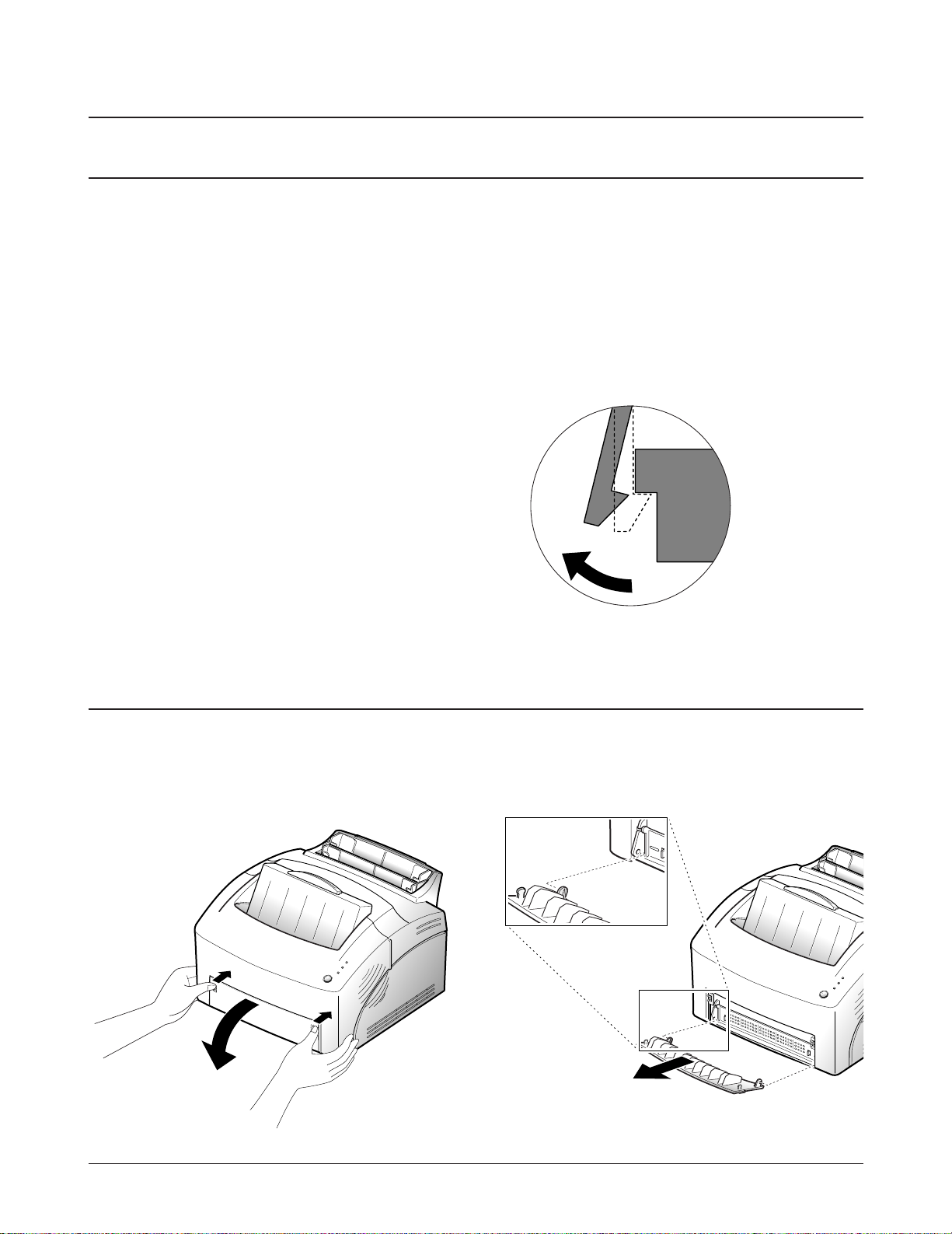
Releasing Plastic Latches
Samsung Electronics 3-1
Many of the parts are held in places with plastic
latches. The latches break easily; release them
carefully. To remove such parts, press the hook
end of the latch away from the part to which it is
latched.
3-2 Face-Up Cover and Front Cover
1. Place your fingers on both sides of the face-up
cover, push the cover, and pull it down.
2. Bend the cover slightly to release the tabs at the
end, then remove the cover.
3-2 Samsung Electronics
Disassembly and Reassembly
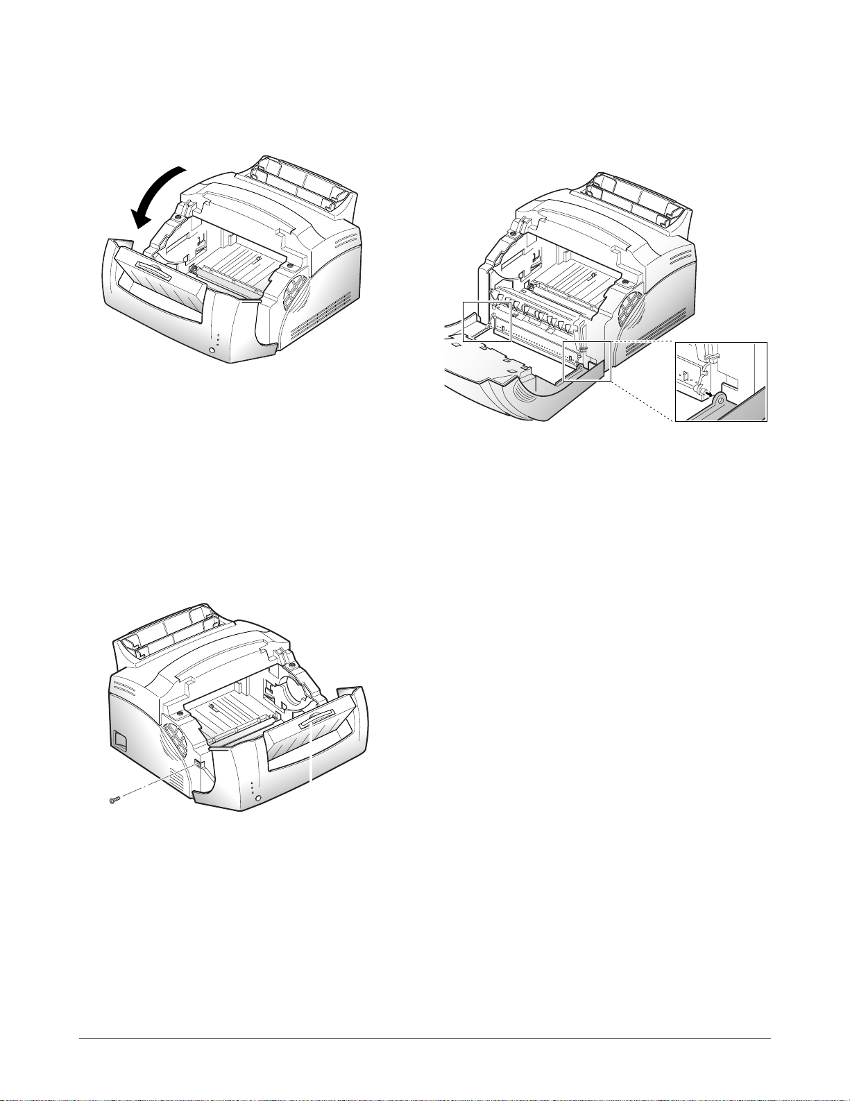
3. Open the front cover with hand. 5. Unlatch the front cover, then remove the front
cover.
4. Remove a screw securing the front cover to the
main frame.
3-3
Samsung Electronics
Disassembly and Reassembly
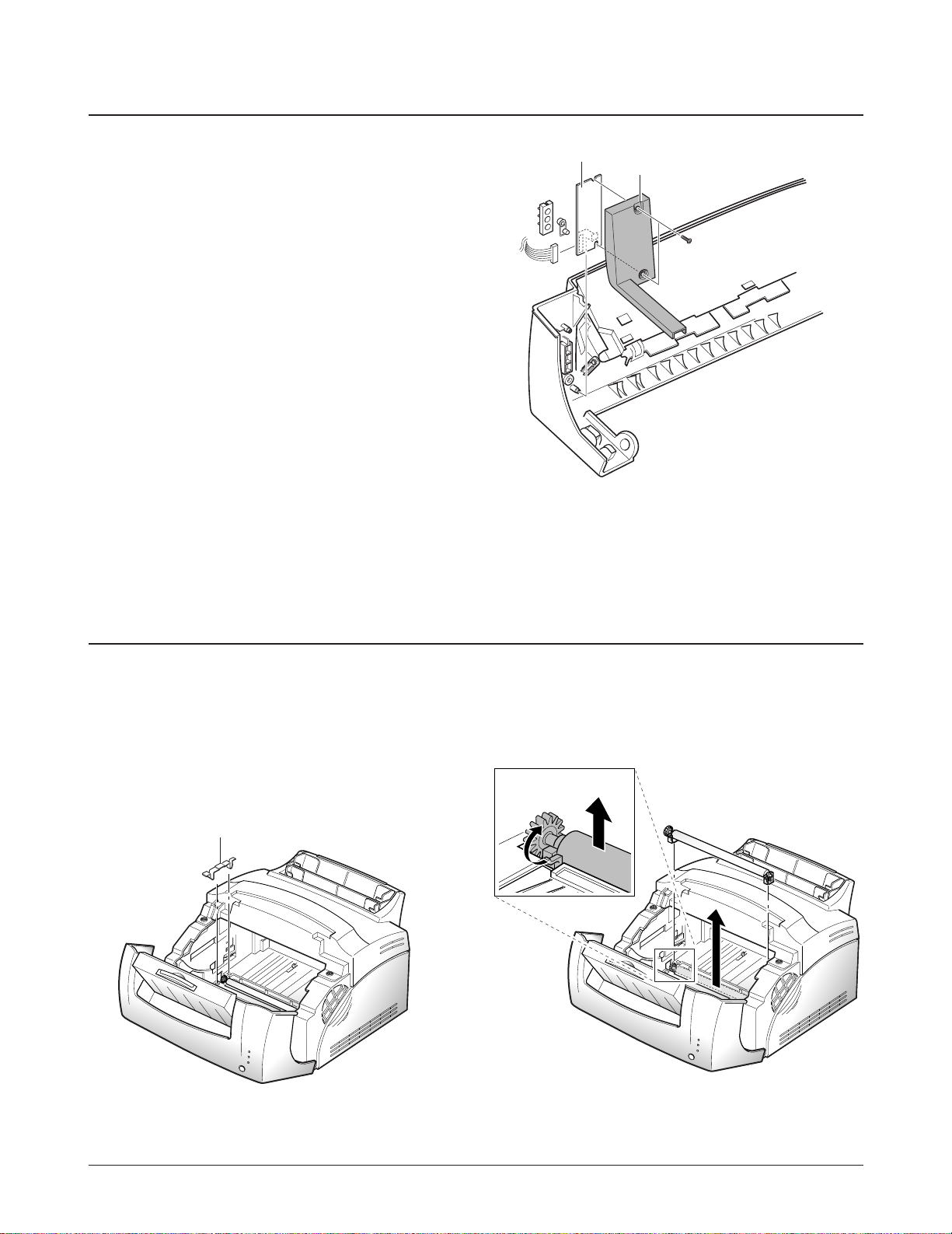
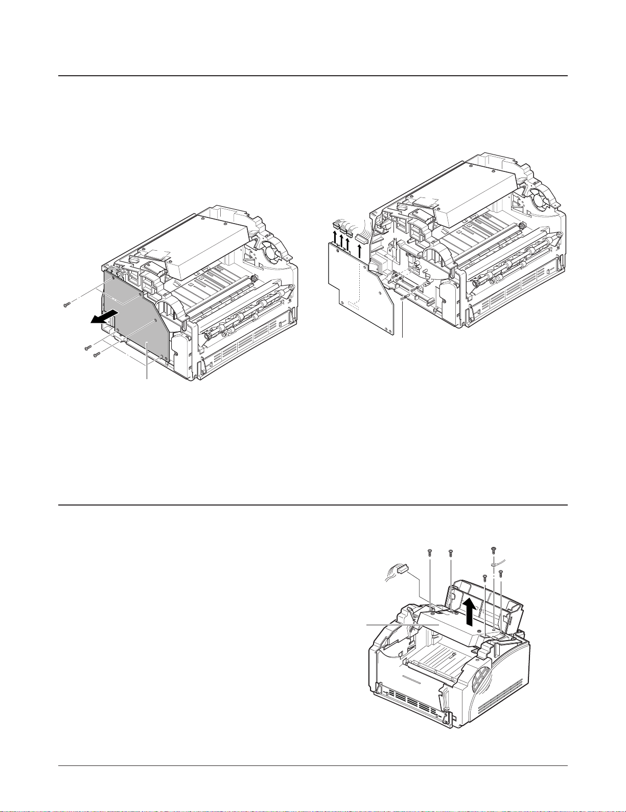
3-3 Panel Board and Board Cover
1. Before you remove these parts, you should
remove:
-Face up cover and Front cover
(see page 3-1)
2. From the front cover, remove two screws,
then remove the board cover.
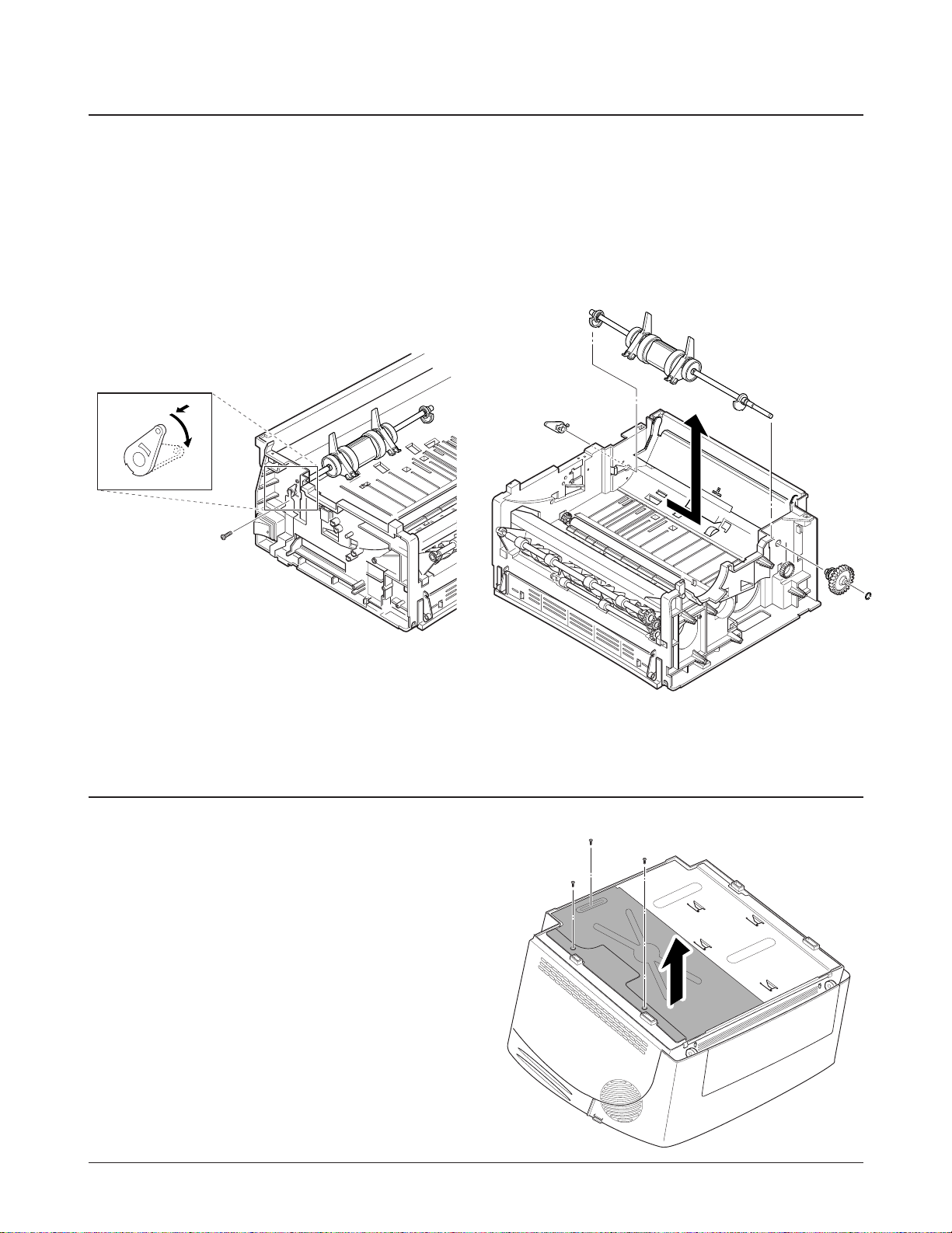
3-4 Transfer Roller
1. Open the front cover with hand.
2. Remove the transfer roller cap.
3. To remove the transfer roller, pull up the tab to
release the roller, then take it out.
Cap
Panel board
Board cover
3-4 Samsung Electronics
Disassembly and Reassembly
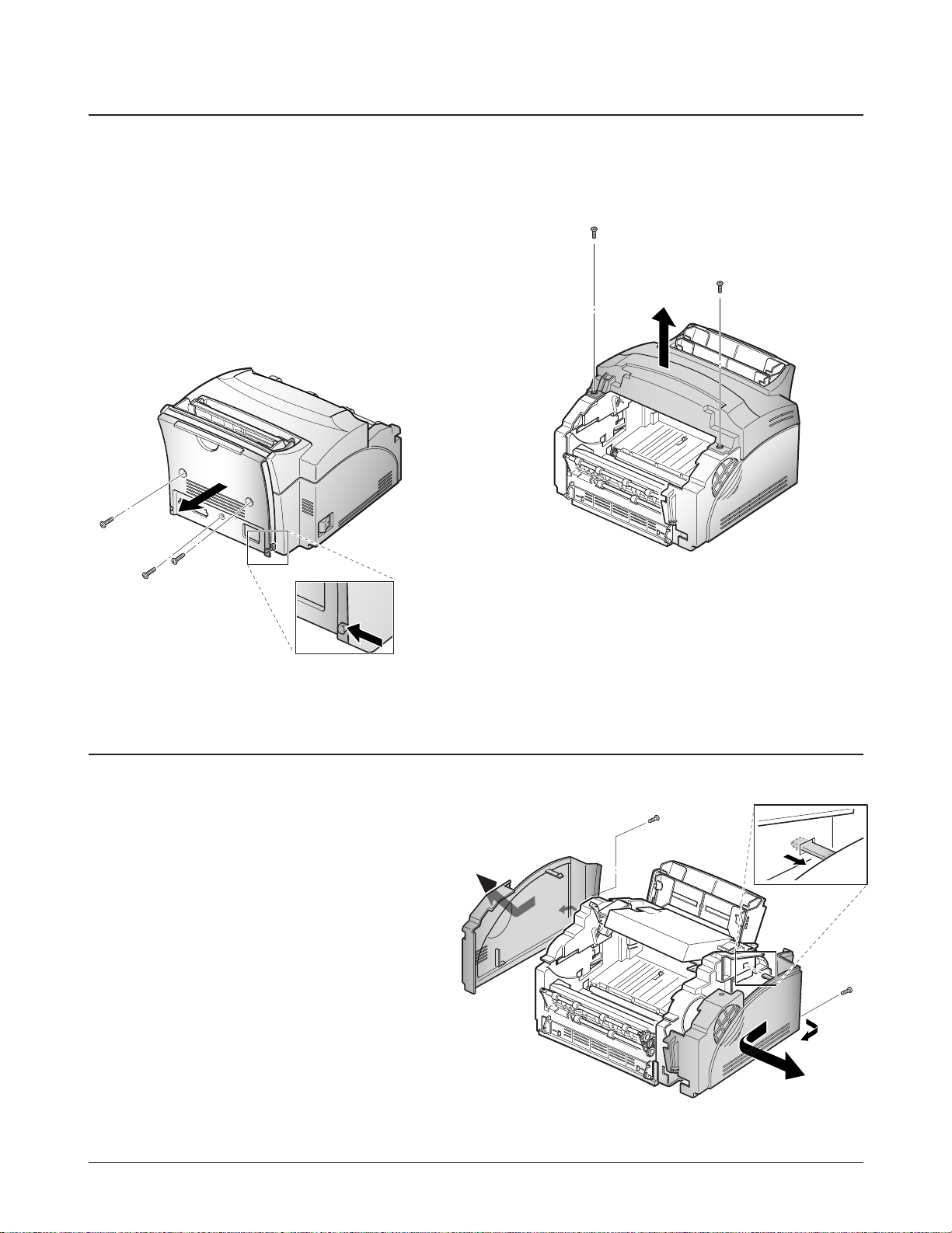
3-5 Top Cover and Rear Cover
1. Before you remove these covers, you should
remove:
-Face up cover and Front cover (see page 3-1)
2. Remove three screws.
3. Unlatch the tabs on the left and right side end of
the cover, then take out the rear cover.
4. Remove two screws, and remove the top cover.
Unlatch the tabs at both
sides to remove the cover.
3-6 Side Covers (Left, Right)
1. Before you remove these side covers, you should
remove:
-Face up cover and Front cover (see page 3-1)
-Top cover and Rear cover (see page 3-4)
2. Remove two screws on the back of the covers.
3. Unlatch the left and right side covers, and
remove them.
3-5Samsung Electronics
Disassembly and Reassembly
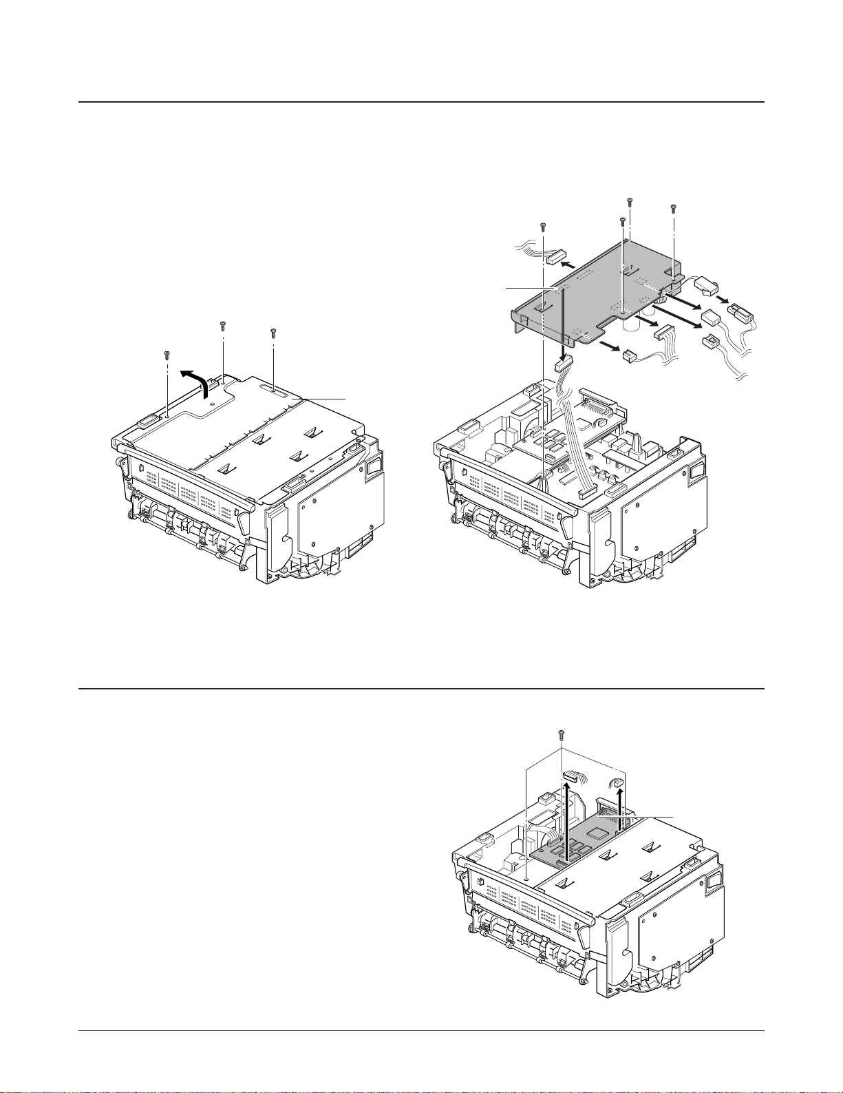
3-7 SMPS/Engine Control Board
1. Before you remove the board, you should
remove:
-All covers (see pages 3-1, 3-4)
2. Turn the printer upside down.
3. Remove three screws securing the shield, then
remove the shield.
4. Unplug all the connectors from the SMPS, then
take out the SMPS and the engine board.
3-8 Control Board
1. Before you remove the control board, you should
remove:
-All covers (see pages 3-1, 3-4)
2. Unplug all the connectors from the control board,
remove three screws, and take out the control
board.
Shield
SMPS and
Engine board
Control Board
3-6 Samsung Electronics
Disassembly and Reassembly
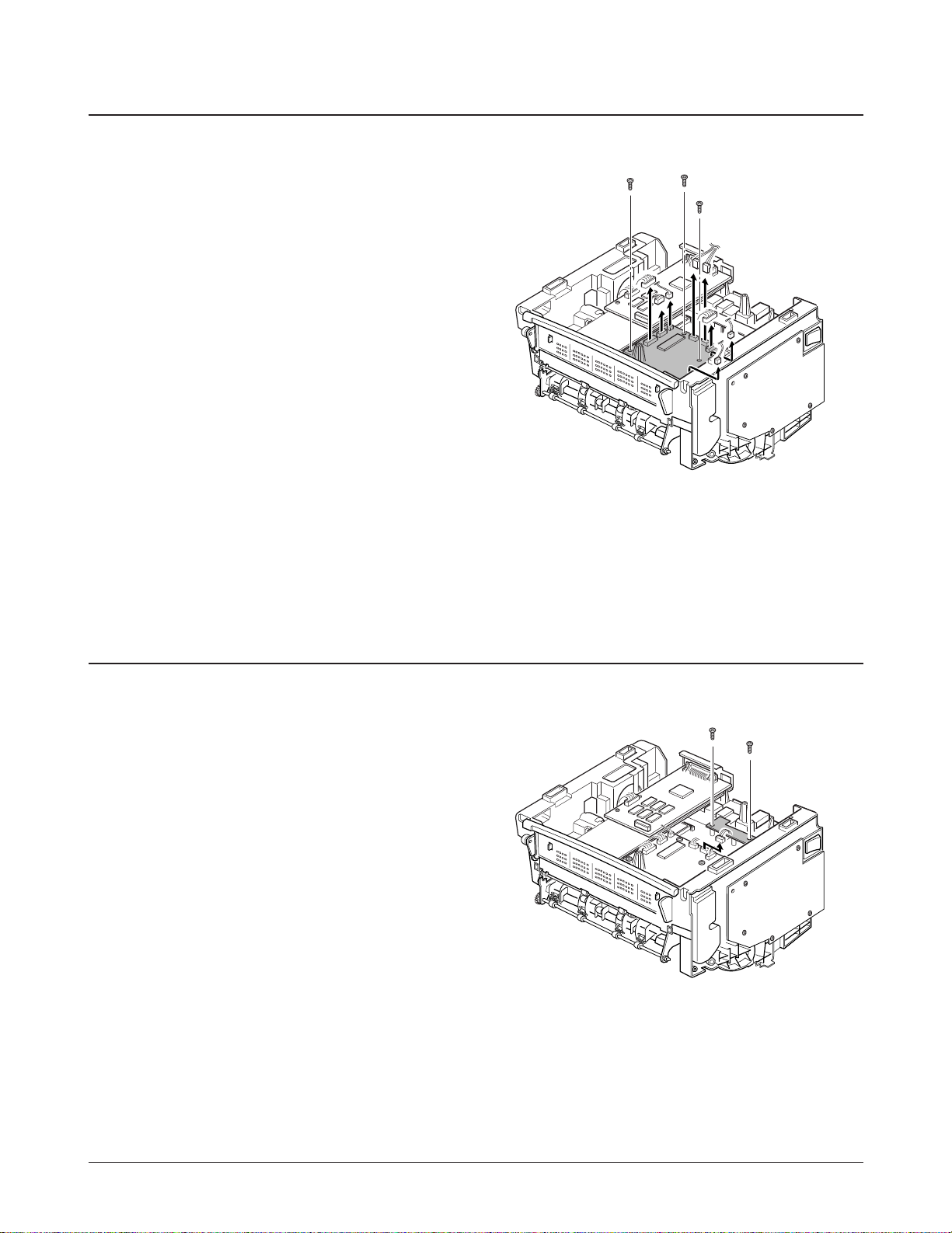
3-9 Joint Board
1. Before you remove the joint board, you should
remove:
-All covers (see pages 3-1, 3-4)
-SMPS (see page 3-5)
2. Unplug all connectors from the joint board,
remove three screws, then remove the joint
board.
3-10 Sensor Board
1. Before you remove the sensor board, you should
remove:
-All covers (see pages 3-1, 3-4)
-SMPS (see page 3-5)
2. Remove two screws, unplug all connectors from
the sensor board, then remove the board.
3-7Samsung Electronics
Disassembly and Reassembly
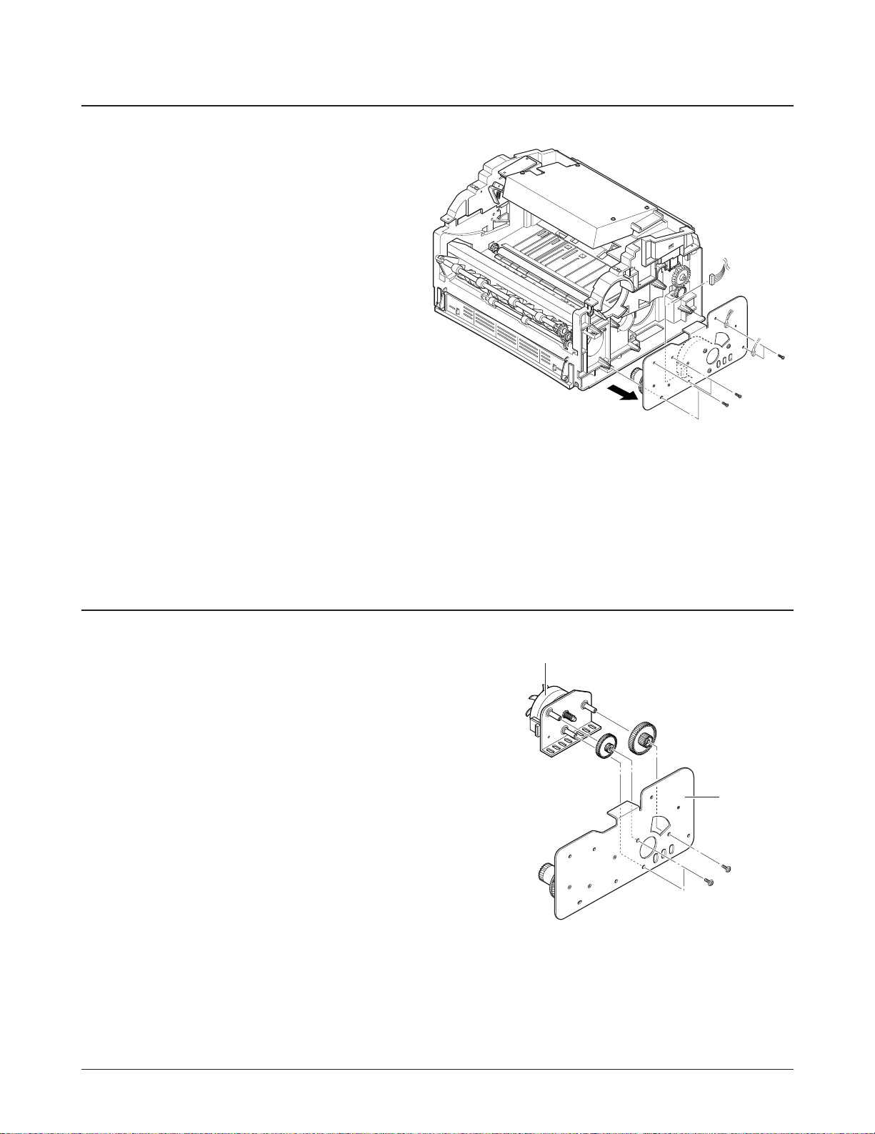
3-11 Gear Bracket
1. Before you remove the gear bracket, you should
remove:
-All covers (see pages 3-1, 3-4)
2. Remove six screws securing the gear bracket,
unplug the connector from the motor, then
remove the gear bracket.
3-12 Motor
1. Before you remove the motor, you should
remove:
-All covers (see pages 3-1, 3-4)
-Gear bracket (see page 3-14)
2. Remove three screws, then remove the motor.
Motor
Gear bracket
3-8 Samsung Electronics
Disassembly and Reassembly
3-13 HVPS Board
1. Before you remove the HVPS board, you should
remove:
-All covers (see pages 3-1, 3-4)
2. Remove five screws from the HVPS board.
3. Unplug the connector from the HVPS board,
then remove the board.
Note: When you reassemble the HVPS board, make
sure that the high voltage electrodes are
placed correctly.
3-14 LSU
1. Before you remove the LSU, you should remove:
-All covers (see pages 3-1, 3-4)
2. Unplug two connectors, remove five screws, then
take out the LSU.
HVPS board
High voltage electrodes
LSU
3-9Samsung Electronics
Disassembly and Reassembly
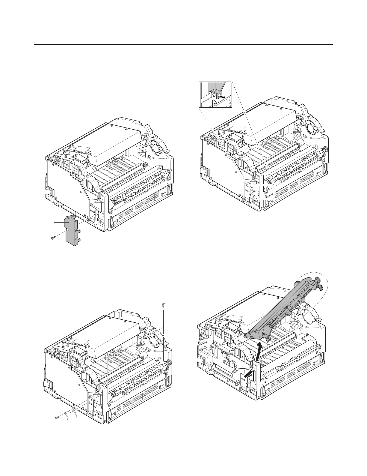
3-15 Fuser
1. Before you remove the fuser, you should remove:
-All covers (see pages 3-1, 3-4)
2. Remove one screw securing the wire cap at the
left side of the frame, unlatch the cap, then
remove the cap.
4. Unlatch the tabs using a proper tool.
5. Slide the fuser in the direction of arrow and take
it out.
3. Remove four screws.
Wire cap
Unlatch these tabs.
3-10 Samsung Electronics
Disassembly and Reassembly
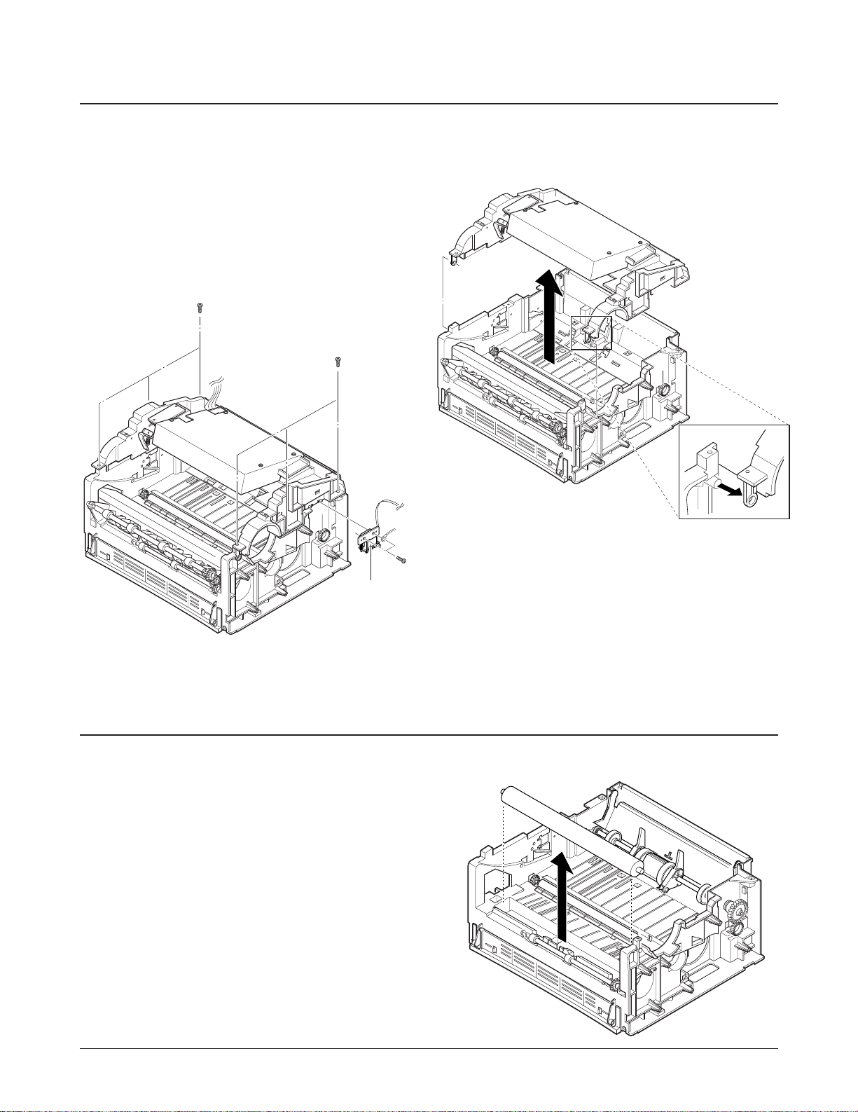
3-16 Upper Frame
1. Before you remove the upper frame, you should
remove:
-All covers (see pages 3-1, 3-4)
-Gear bracket (see page 3-14)
-HVPS board (see page 3-16)
2. Remove six screws, then remove two screws
securing the solenoid.
3. Unlatch the front end of the frame, then lift it up.
3-17 Pressure Roller
1. Before you remove the roller, you should
remove:
-All covers (see pages 3-1, 3-4)
-All boards (see pages 3-3, 3-5, 3-6, 3-8)
-Upper frame (see page 3-10)
-Fuser (see page 3-9)
2. Remove the roller.
Solenoid
Samsung Electronics 3-11
Disassembly and Reassembly
3-18 Pickup Roller
1. Before you remove the pickup roller, you should
remove:
-All covers (see pages 3-1, 3-4)
-All boards (see pages 3-3, 3-5, 3-6, 3-8)
-Upper frame (see page 3-9)
2. Remove one screw, pull the pick-up bushing
slightly toward you, then rotate it clock-wise.
3. Remove the E-ring at the right end of the roller.
4. Remove a pin passing through a shaft to take out
the pick-up roller, then push the roller shaft to
the right. Lift the left side of the roller, then take
it out.
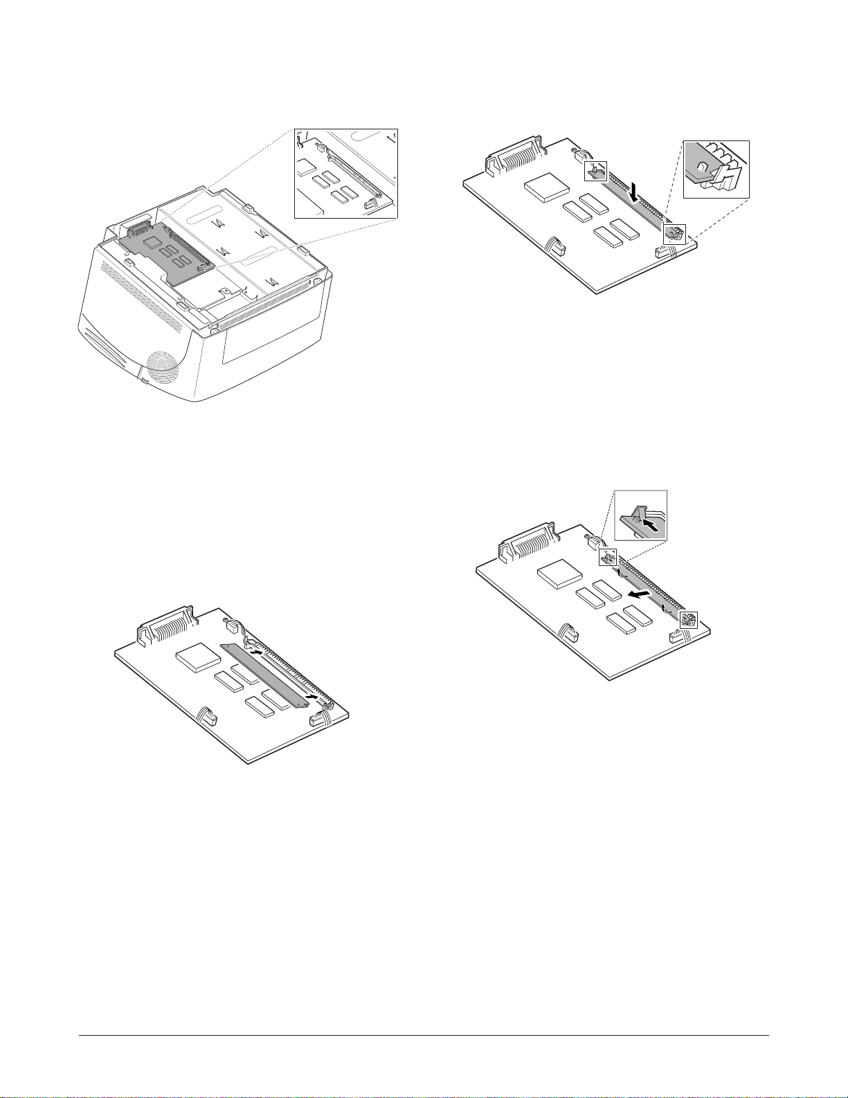
3-19 Installing SIMM
1. Before you install SIMM, make sure that printer
power is off, all cables are unpluged. The toner
cartridge is also to be removed.
2. Turn the printer upside down, and remove all
screws securing the shield cover, then remove
the shield cover.
3-12 Samsung Electronics
Disassembly and Reassembly
5. Push it firmly until it snaps into place.
Make sure both metal clips on the connector are
fastened and the two pins on the connector are
pushed through the holes on the SIMM.
Note: When you disassemble the SIMM, push
out on the metal clips at each end of the
connector and pull it toward you.
6. Reassemble the shield cover.
3. Locate the SIMM connector on the control board.
4. Hold the SIMM with the connection points and
insert the SIMM all the way into the connector at
30oangle .
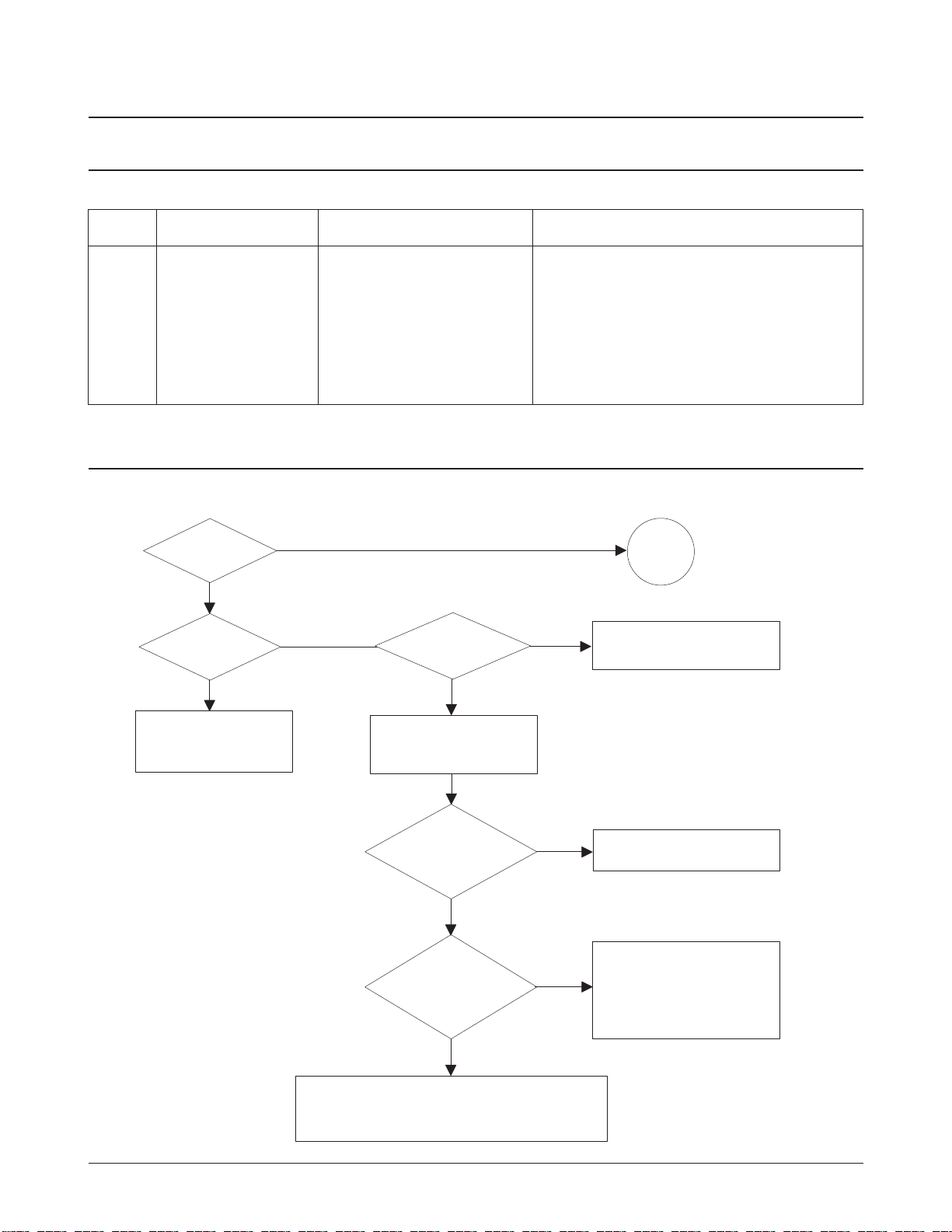
4. Troubleshooting
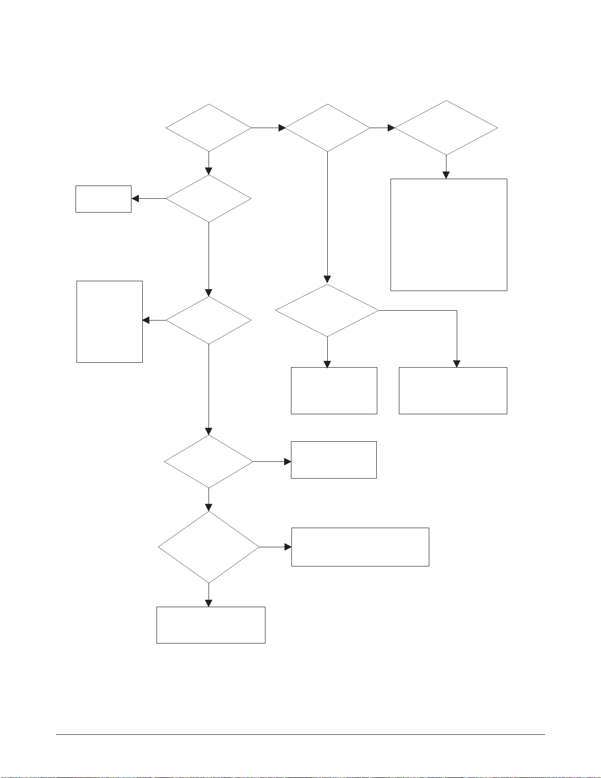
4-1 Abnormal Image Printing and Defective Roller
If abnormal image prints periodically, check the parts shown below.
Samsung Electronics 4-1
No Roller Abnormal image period Kind of abnormal image
1 OPC Drum 94.3mm White spot
2 Charge Roller 37.7mm Black spot
3 Supply Roller 40.0mm Horizontal density band
4 Develop Roller 46.1mm Horizontal density band
5 Transfer Roller 47.1mm Black side contamination/transfer fault
6 Heat Roller 56.1mm Black spot and fuser ghost
7 Pressure Roller 56.2mm Black side contamination
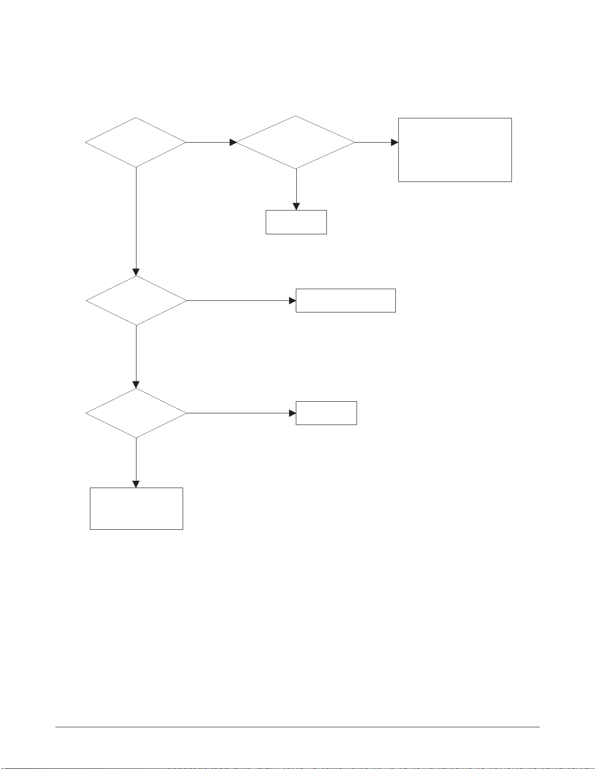
Check connection to
computer or replace
controller.
Take out the cartridge
and prepare the tester
for electronic connection.
Repair or replace the GND
terminal.
Check the path between
video controller, engine board
and HVPS. Repair or replace
the defective component
or board.
The mirror in LSU might be misplaced so the light
path to the OPC deviates ->Repair or replace LSU
or remove any defective matters in the machine.
Self test
pattern prints?
No image?
Self testing
is possible via
DCU?
Is the OPC
terminal of machine
well-connected
to Frame?
Does the
video data line to
LSU transit to High/Low
when printing?
Re-test after replacing the
conector or controller board.
A on
next page
NO
NO
NO
NO
NO
YES
YES
YES
YES
YES
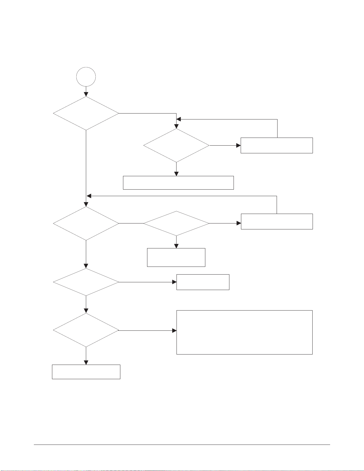
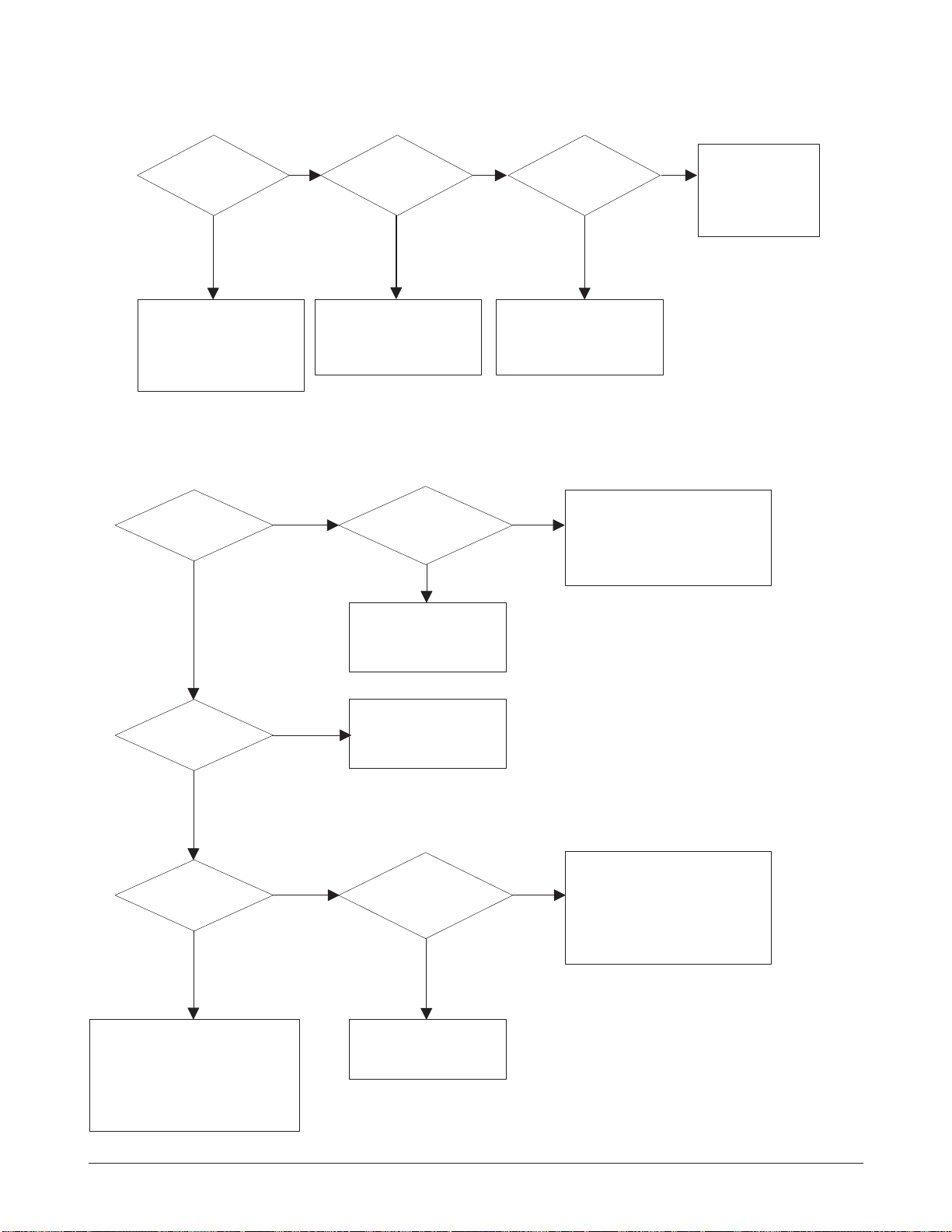
4-2 Print Quality
4-2-1 No Image
4-2 Samsung Electronics
Troubleshooting
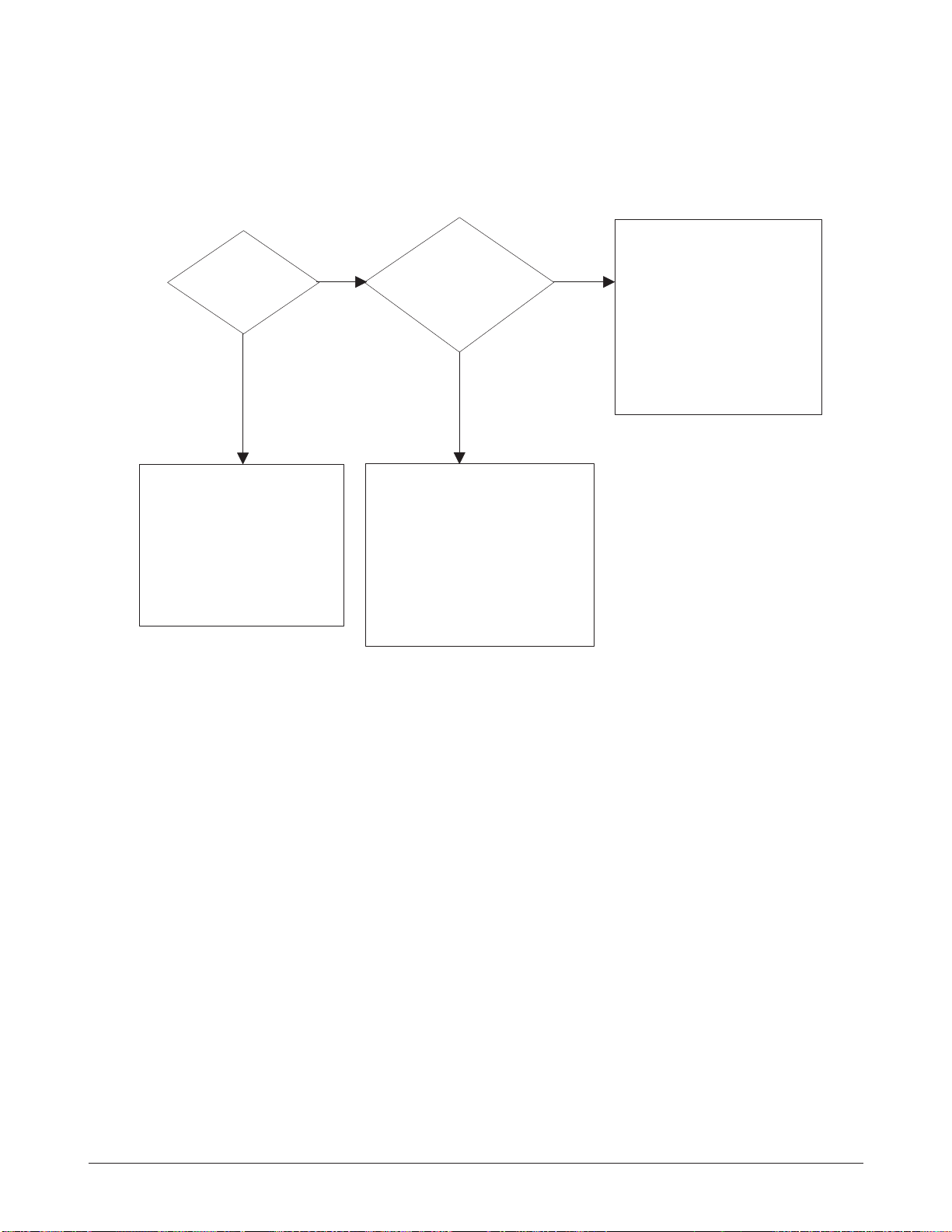
Transfer roller might be out of its location.
-> Locate the roller into its place.
This could occurrs when the power of LSU is low or
the density is low due to the obstacles on the window
-> Replace LSU or clean the window.
A
Transfer
voltage OK? (on the
transfer roller
shaft)
Are the
connection terminal
and connection
correct?
Repair or replace terminal.
Sealing tape
is removed from the
cartridge?
Replace HVPS or repair defective component.
Is the connection
terminal OK?
Replace HVPS or repair
defective component.
Repair or replace terminal.
Remove the tape.
Developing
(-300V) and supplying
(-500V) voltage
are OK?
Does the
counter indicate over
the toner's guarranty
life?
Replace the toner cartridge.
NO
NO
NO
NO
NO
NO
YES
YES
YES
YES
YES
YES
4-3
Samsung Electronics
Troubleshooting
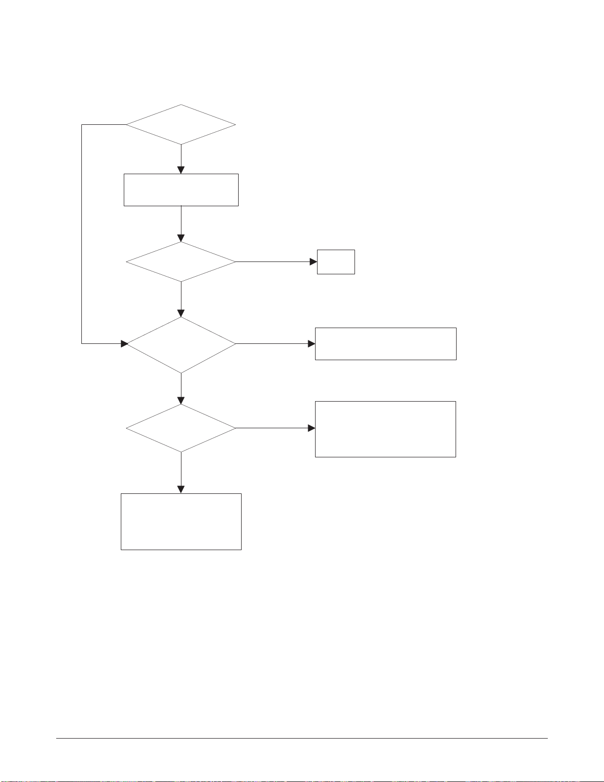
All black in
printing area?
Is transfer
voltage supplied
from HVPS?
Is the
Hsync/ signal received
in LSU?
Transfer part's contact
is bad. -> Repair or
replace toner cartridge.
Does the
video data line to LSU
transit to High/ Low when
printing?
Replace LSU.
Check the path among video
controller, engine board,
HVPS, LSU for the shortage
or open. -> Repair or replace
the boards.
Repair or replace HVPS.
Replace LSU.
NO
NO
NO
NO
YES
YES
YES
YES
4-2-2 All Black
4-4 Samsung Electronics
Troubleshooting
White line
missing definitely?
Dirt of dust stuck onto the
window of internal lens of LSU
-> Clean it or replace LSU.
Preventive obstacles through
the path between OPC of
developer and LSU prevent the
path -> Remove the obstacles.
Check if the
printout is still has the
same problem even right after
passed through the
transfer roller.
Toner material might be stuck to
blade in the developer inside and it
prevents toner supply -> Replace
the developer.
Check both if the toner cartridge's
counter is over its guaranty and
amount of the toner material.
-> Replace the toner cartridge.
The ribs in fuser or toner on the
roller may invoke the image
problem. -> Replace the fuser
cover or the defective part.
The image is originally black or the
black part is far close to the top.
-> Use the pattern which has the
image below bigger than 10mm
from the top.
NO
NO
YES
YES
4-2-3 Vertical White Line (Band)
4-5Samsung Electronics
Troubleshooting
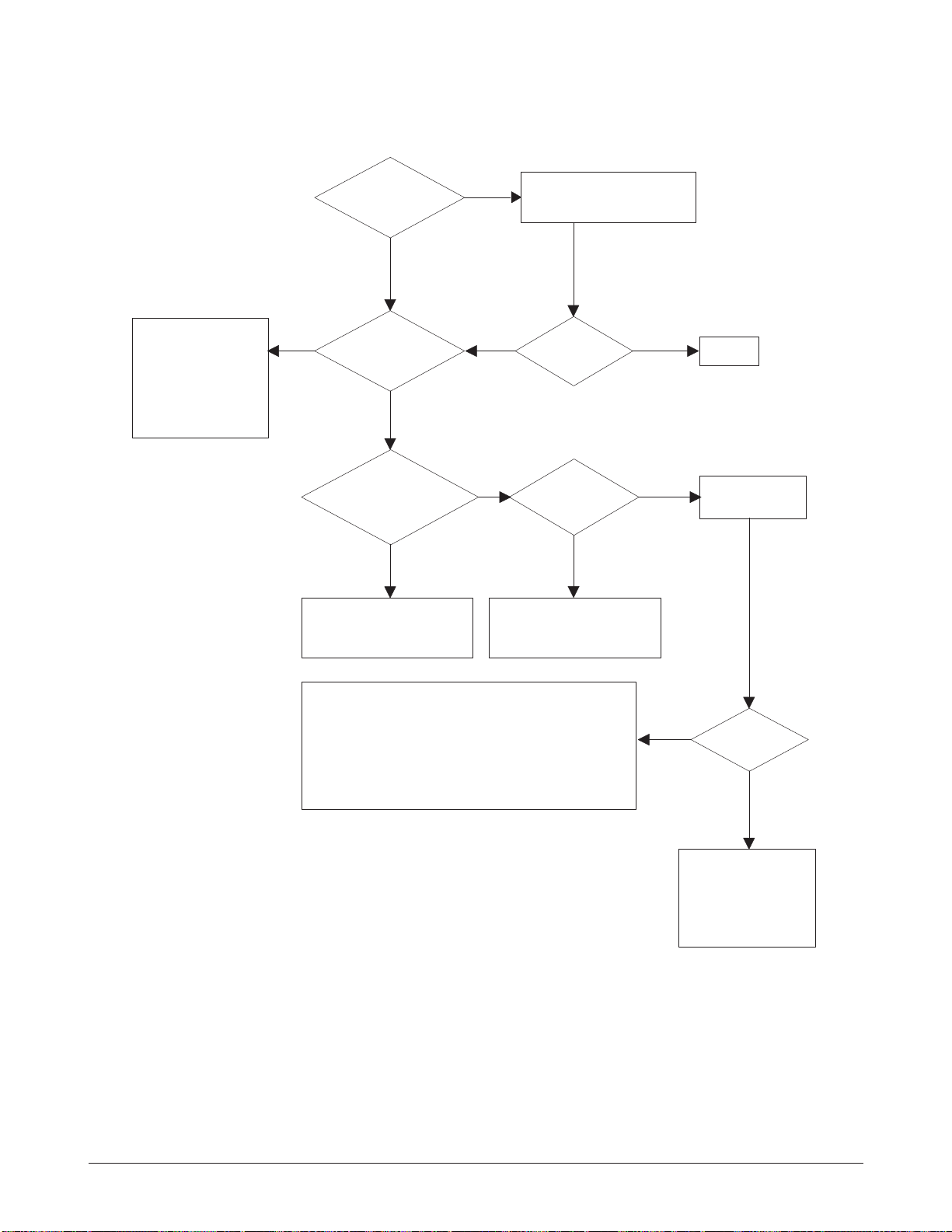
'Dark' selected
via RCP?
Change to
'Normal' and test.
Works
correctly with
-300V of Bias
voltage?
Works
correctly after
replaced LSU?
Repair or replace the defective
component.
The power of LSU is set
high or internal problem.
-> Replace LSU or adjust
volume.
Same at 'Normal'?
END
NO
NO
NO
Toner over supply due to the
adjustment fault of metering
blade in developer.
-> Replace developer.
NO
YES
YES
YES
YES
4-2-4 Dark Image
4-6 Samsung Electronics
Troubleshooting
Recommended
paper used?
Transfer,
charge and developing
voltage are OK?
Operating/
storage atmosphere is
too high temperature
/humidity?
Solve the problem under
the recommended condition
(10-32 degree Centigrade).
Dirt or
dust around the
charge roller?
Clean the charge roller
or replace step-up device
/terminal after check.
Work OK?
Internal blade or
suppying part of the
developer is defective.
-> Replace the toner
cartridge.
Check terminals or contacts and 'Guide-Deve Spring'
are misplaced.
-> Repair or replace transfer roller etc.
Check if the LED of PTL in front of the transfer roller
is on when it presses the top cover switch on purpose.
-> If not, replace PTL.
Print 20 to 30 pages using
the recommended paper.
Same problem
occurs?
- Adjust voltage or
replace HVPS.
- Repair or replace
after checking the
terminals' contacts.
END
Replace the
toner cartridge.
NO
NO
NO NO
NO
NO
YES
YES
YES
YES
YES
YES
4-2-5 Background
4-7Samsung Electronics
Troubleshooting
YES
Is it regular
interval of 94mm?
PTL lamp
works OK?
Transfer
voltage is set to
standard?
Is it regular
interval of 46mm?
Is it regular
interval of 47mm?
(as transfer roller
interval)
Developing
/suppying voltage
normal? (-300V/
-500V)
Check HVPS
contacts and
HVPS's selfoutput.
-> If failed,
repair/replace
HVPS.
Replace PTL
assembly.
Irregularity of NIP
between rollers in
developer.
-> Replace developer.
- Repair or replace HVPS .
- Check and repair or
replace the terminal
contacts.
A specific part of the transfer
roller has ruined or its
resistance value is changed.
-> Replace transfer roller.
Transfer roller cannot force
regularly due to the gears
eccentricity of transfer roller.
-> Replace the defective
component.
Bias voltage
is OK? (-300V)
Operating/storage
temperature is too low or
not recommended
paper used?
Adjust the Bias
voltage or replace
HVPS.
There may be a problem in toner
layer control in toner cartridge.
-> Replace the developer.
Use the machine with
recommended paper and
at normal condition.
NO
NO
NO
NO
NO
NO
NO
YES
YES
YES
YES
YES
YES
YES
4-2-6 Ghost
4-8 Samsung Electronics
Troubleshooting
Is it regular
interval of 38mm?
The problem occured
since the obstacles
stuck to charge roller.
-> Replace developer
and C/R.
When taking
out the cartridge,
toner leaks?
Toner leaks and toner
material dropped onto
the paper. -> Replace the
developer.
Bad image
removes by
scratching?
Check toner is stuck onto
the P/R or H/R in fuser.
-> Clean it or replace.
The problem
randomly occured
due to the toner
fallen. -> Clean the
machine.
NO NO NO
YES
YES
YES
4-2-7 Black Dot
NO
Black band?
The black
band has regular
interval?
Black band
is far about 10mm from
white band?
Problem of internal
contacts in OPC.
-> Replace developer.
The OPC is damaged under the
direct sunlight for around 5
minutes. -> If the same problem
persists in 10 hours, replace
the developer.
This occurs when no
Hsync/ at LSU.
-> Replace LSU.
94mm interval?
Heat roller is ruined.
-> Replace the roller.
The OPC is damaged due to
the irregular transfer voltage
of HVPS.
-> Repair/replace HVPS.
-> If the same problem persists,
replace the developer.
Does it appear
at every 56.1mm at
specific place?
Problems of terminal contact,
transfer voltage supplying,
and transfer roller's due to the
charge roller is ruined (38mm).
-> Repair/replace HVPS,
developer.
NO
NO NO
NO
YES
YES
YES
YES
4-2-8 Horizontal Band
 Loading...