

Page 1

Troubleshooting
4-1
Samsung Electronics
4. Troubleshooting
4-1 How to use DCU
4-1-1 DCU Setup......................................Page(4-2)
4-1-2 Code ................................................Page(4-2)
4-1-3 Self Diagnostic Mode......................Page(4-3)
4-1-4 Self Test Button................................Page(4-4)
4-1-5 Paper Path Layout...........................Page(4-4)
4-2 The cause and solution of Bad image
4-2-1 Vertical Black Line and Band..........Page(4-5)
4-2-2 Vertical White Line...........................Page(4-5)
4-2-3 Horizontal Black Band .....................Page(4-6)
4-2-4 Black/White Spot..............................Page(4-6)
4-2-5 Light Image.......................................Page(4-7)
4-2-6 Dark Image or a Black.....................Page(4-7)
4-2-7 Uneven Density................................Page(4-8)
4-2-8 Background ......................................Page(4-8)
4-2-9 Ghost (1)...........................................Page(4-9)
4-2-10 Ghost (2)..........................................Page(4-9)
4-2-11 Ghost (3)..........................................Page(4-10)
4-2-12 Ghost (4) .........................................Page(4-10)
4-2-13 Satins on the Face of Page............Page(4-10)
4-2-14 Satins on Back of Page..................Page(4-11)
4-2-15 Blank Page Print out (1) .................Page(4-11)
4-2-16 Blank Page Print out (2) .................Page(4-11)
4-3 The cause and solution of the bad discharge
4-3-1 Wrong Print Position.......................Page(4-12)
4-3-2 JAM 0...............................................Page(4-12)
4-3-3 JAM 1...............................................Page(4-13)
4-3-4 JAM 2...............................................Page(4-13)
4-3-5 Multi-Feeding...................................Page(4-14)
4-3-6 Paper rolled in the fuser .................Page(4-14)
4-3-7 OPC.................................................Page(4-15)
4-4 The cause and solution of the malfunction
4-4-1 All LEDs blinking (Fuser Error)........Page(4-16)
4-4-2 All LEDs blinking (SCAN ERROR).Page(4-16)
4-4-3 Not function of the gear of the fuser due to
melting away.....................................Page(4-17)
4-4-4 Paper Empty.....................................Page(4-17)
4-4-5 Paper Empty without indication.......Page(4-17)
4-4-6 Cover Open......................................Page(4-18)
4-4-7 No lamp on when the cover is open
...........................................................Page(4-18)
4-4-8 Defective motor operation ...............Page(4-19)
4-4-9 No Power..........................................Page(4-19)
4-4-10 Vertical Line Getting Curved.........Page(4-20)
4-5 Toner Cartridge Service
4-5-1 Precautions on Safe-keeping of Toner Cartridge
..........................................................Page(4-21)
4-5-2 Service for the Life of Toner Cartridge
..........................................................Page(4-21)
4-5-3 Service for Judgement of Inferior Expendables
and the Standard of Guarantee.....Page(4-21)
4-5-4 Signs and Measures at Poor toner cartridge
..........................................................Page(4-22)
4-6 The cause and solutions of bad environment
of the software
4-6-1 The printer is not working (1)...........Page(4-25)
4-6-2 The printer is not working (2) .........Page(4-26)
4-6-3 Abnormal Printing.............................Page(4-27)
4-6-4 SPOOL Error ...................................Page(4-28)
Page 2

Troubleshooting
4-2
Samsung Electronics
4-1 How to use DCU
4-1-1 DCU Setup
You can examine the malfunction of the printer. To perform DCU, open the front discharge cover and leave the connect
the harness wire(10 pin/4 pin) to the CN10(4 pin) of the Main control board.
4-1-2 Code
Connect DCU to the printer and turn the power on. It show 7 LED on the panel and each code tells the function of the
printer.
Normal Code
While printing or warming up, it indicate the position of the paper
61 Warm up The printer is on, the cover is open or close.
00-05 Ready(kind of paper) The printer is ready, the paper is detected when the first paper is printed.
00: Legal , 01: Letter , 02: A4 , 03: EXEC , 04: B5 , 05: Folio
20 Print Start The engine controller received the print order from the video controller.
30 Feed Sensor On The paper is passing out of the Feed Sensor.
40 Feed Sensor off The paper has passed out of the Feed Sensor.
50 Paper Out The paper has passed out of Exit Sensor.
69 Sleep Mode The fuser power turned off to minimize the power consumption.
Error Code
When detecting the malfunction, the printing is stopped to indicate error code.
60, 62, 68
Fuser Error The error in the fuser occurred. There is a short circuit in the thermistor and the
thermostat while printing, Low Temperature Error occurs.
• 60: Open Fuser Error
• 62: Low Heat Error
• 68: Over Heat Error
64 Cover Open The Printer Cover is open or Toner Cartridge not installed.
70 No Paper No paper in the paper cassette.
71 Paper Jam 0 The front part of paper is jammed between pickup unit and Feed sensor.
72 Paper Jam 1 The front part of paper is jammed between the Discharge sensor and Feed sensor.
73 Paper Jam 2 The front part of paper is jammed just after passing through the discharge sensor.
95 LSU Not Ready LSU Scanner Motor not ready or Hsync signal not output.
Page 3

Troubleshooting
4-3
Samsung Electronics
4-1-3 Self Diagnostic Mode
If Error code occurs due to malfunction of the printer, perform Self Diagnostic Mode to solve the problem.
The printer works only in the self-test mode to solve the malfunction problem.
To enter the self-test mode, turn the power on pressing the buttons of [Down], [Shift] and [Stop] at the same time.
Release the button within 2 or 3 seconds if 78 shows in the DCU. If 00 shows in the DCU, press the button [Up] or [Shift]
to select the self+test , and press the button of [Enter] to operate. To stop, press the button of [shift] and [Enter] together.
00 Main Motor Operating System
Only the main motor is in operation.
01 Main High Voltage On(THV-)
-1550 voltage output by MHV terminal. Caution : High voltage probe should be
used.
02 Transfer High Voltage(-)On(THV-)
-1300 voltage output by MHV terminal. Caution
:
High voltage probe should be
used.
03 Transfer High Voltage (+)Reference on (THV +)
1300 voltage output by MHV terminal. Caution : High voltage probe should be used.
04 DEV/supply High Voltage : DEV/Supply High Voltage Test.
The left one of the three LEDs in the
self-test panel is on when DEV high voltage Supply high voltage output
by each HV terminal. Press the [Up] button to switch the voltage. The middle and right one of the three
LEDs
are on and -530 voltage output by DEV HV terminal.
Caution : High voltage probe should be used.
05 LSU Operating System
The scanning motor of LSU is in operation, the right LED of the three buttons on. Press the [Up] button to
Check LD. LD is functioning and the middle button is on. If the LD is normal, all LEDs are on.
06 Pickup clutch on
The Solenoid in the printer is in operation. To stop the operation, Press the button [shift] and [Enter] together.
07 Pempty/PWIDTH/New CRU Sensor Test : Pempty/PWIDTH.HEW CRU sensor test.
If activate the Actuator of the PEMPTY/PWIDTH Sensor, the left and right of the three LEDs are on.
If you install new toner Cartridge in this mode, the right LED is on.
08 Feed & Exit Sensor Test
Test the Feed sensor and Discharge sensor in the same way as '06'.
09 Cover Open Sensor Test
The same way as code '06'.
10 Fuser Test
If the [Enter] button pressed, the right LED is on and temperature of the fuser is up to READY Mode. If the
[Up] button pressed, the middle LED is on and temperature of the fuser is up to Printing Mode.
If you press the button once more, the left LED is on and temperature of the fuser is up to overheat Mode.
11 Hot Burn Test
If the [enter] button pressed, the printer is continuously printing without detection. Turn the power off to stop
operation.
12. Cleaning Mode Print Mode
Print the paper to clean the OPC Drum in the Cartridge.
Page 4
Troubleshooting
4-4
Samsung Electronics
13. THV(+) TRIGGER. ALL HV
All high voltage output by each HV terminal and LSU and the fan is in operation. In this mode, electronic
resistance of transfer roller and high voltage is detected. If no toner cartridge in the printer, output of THV is
+199V ~ + 2100V.
14. PTL Test
Indicates the PTL LED.
15. Fan Test
Indicates the function of the fan.
4-1-4 Self Test Button
If the Self-Test button pressed, vertical lines are printed.
Turn the power on while pressing this button, '89' shows in the DCU and the printer is warming up. After warming-up the
printer is in READY Mode, and '88' shows in the DCU. In this mode, without any detection, the printer begins
printing(trial printing and data from the PC). It is convenient to use this mode when the engine malfunction is detected in
the control board.
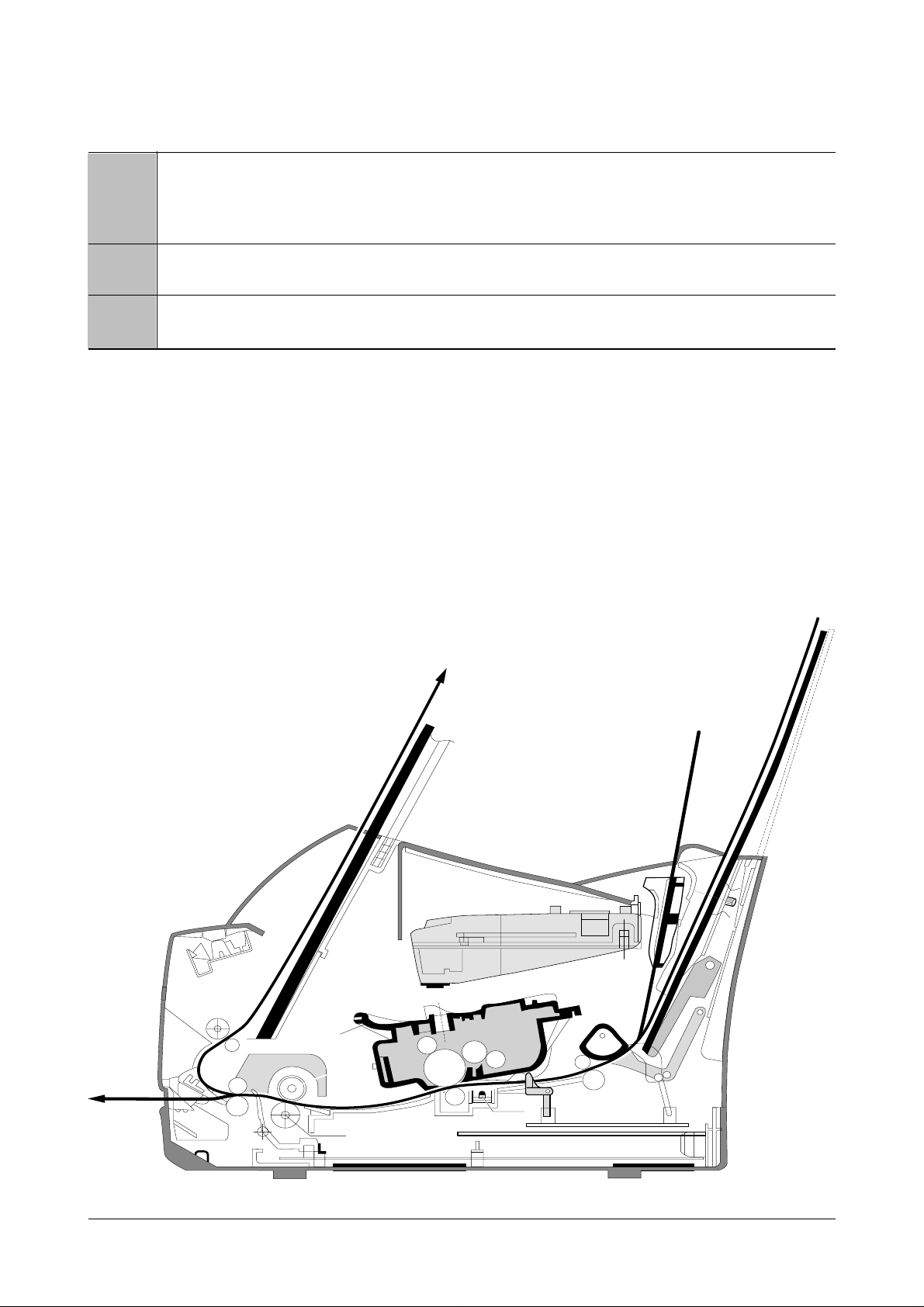
4-1-5 Paper Path Layout
EXIT 2
FUSER
FACE UP
EXIT 1
FEED SEN
EMPTY SEN
KNOCK UPKNOCK UP
LSU
CARTRIDGE
LSU
CARTRIDGE
PICK UP
FEED
IDLE
PTL
DR
SR
RECORDED PAPER (100 SHEETS)
RECORDED PAPER (150 SHEETS)
MANUAL 1 SHEET
EXIT SENSOR
OPC
CR
TR
FACE DOWN
SENSOR BOARDSENSOR BOARD
MAIN BOARDMAIN BOARD
SMPS
SHIELDSHIELD SHIELDSHIELD
H R/L
Pr R/L
Page 5

Troubleshooting
4-5
Samsung Electronics
4-2 The cause and solution of Bad image
4-2-1 Vertical Black Line and Band
• Description
1. Straight thin black vertical line occurs in the printing.
2. Dark black vertical band occur in the printing.
Digital Printer
Digital Printer
Digital Printer
Digital Printer
Digital Printer
Check and Cause Solution
1. Damaged develop roller in the Developer
or deformed Doctor-blade.
2. Scratched surface of the discharge roller
in the developer, or heavily accumulated
foreign matters between the discharge
roller and fur transfer roller/ charge roller.
3. Partly depression or deformation on the
surface of the transfer roller.
1. If causes 1 and 2 occur in the developer
cartridge, replace the developer and try to
print out.
2. Replace the transfer roller if occurred as
No. 3.
4-2-2 Vertical White Line
• Description White vertical voids in the image.
Digital Printer
Digital Printer
Digital Printer
Digital Printer
Digital Printer
Check and Cause Solution
1. Foreign matter stuck onto the window of
internal lenses of LSU mirror.
2. Foreign matter or toner particles between
the developer roller and blade.
(In case the life of the developer has
been expired, white lines occur in front of
the image.)
3. It may occur when Burr and foreign substances are on the window of the developer frame.
4. If the fuser is defective, voids occur periodically at the top of a black image.
1. Foreign matter stuck onto the window :
Clean the LSU window with recommended cleaner(IPA) Clean the window with a
clean cotton swab.
2. Foreign matter in the LSU : Open the
cover of LSU and clean with a cotton
swab on the surface of the reflex mirror.
3. No 3. : Remove the foreign matter and
burr of the exposure window.
4. No. 4. : Open the front cover and check
ribs that corresponds to the position of
the voids. Remove if found.
5. If the problems are not solved, check to
see if the weight of the developer is
below 670g. If so, replace the developer
cartridge.
Page 6

Troubleshooting
4-6
Samsung Electronics
4-2-3 Horizontal Black Band
• Description
1. Dark or blurry horizontal stripes occur in the printing periodically.
(They may not occur periodically.)
Digital Printer
Digital Printer
Digital Printer
Digital Printer
Digital Printer
Check and Cause Solution
1. Bad contacts of the voltage terminals to
developer.
2. The rollers of developer may be stained.
Charge roller = 37 mm
Supply roller = 27 mm
Develop roller = 32 mm
Transfer roller = 47 mm
1. Clean each voltage terminal of the Charge,
Supply, Develop and Transfer roller.
(remove the toner particles and paper particles)
2. Clean the right Gear that has relatively
small gap of the teeth in the OPC.
3. If the malfunction persists, replace the
developer.
4-2-4 Black/White Spot
• Description
1. Dark or blurry black spots occur periodically in the printing.
2. White spots occur periodically in the printing.
Digital Printer
Digital Printer
Digital Printer
Digital Printer
Digital Printer
Check and Cause Solution
1. If dark or blurry black spots occur periodically, the rollers in the Developer may be
contaminated with foreign matte or paper
particles.
( Charge roller : 37 mm interval
OPC drum : 75mm interval)
2. If faded areas or voids occur in a black
image at intervals of 75 mm, or black
spots occur elsewhere, the OPC drum
surface is damaged.
3. If a black image is partially broken, the
transfer voltage is abnormal or the transfer roller's life has expired.
1. Run OPC cleaning Mode Print and run the
Self-test 2 or 3 times.
2. In case of 75mm interval unremovable in 1,
cleanly remove foreign substances stuck on
the OPC location equivalent to black spots
and white spots with a dry duster.
3. The transfer roller guarantees 50,000
sheets printing. If the roller's life is expired,
replace it.
4. In case of 37mm interval unremovable in 1,
take measures as to replace the developer
cartridge and try to print out.
5. Clean the inside of the set against the paper
particles and foreign matter in order not to
cause the trouble.
Page 7

Troubleshooting
4-7
Samsung Electronics
4-2-5 Light Image
• Description The printed image is light, with no ghost.
Digital Printer
Digital Printer
Digital Printer
Digital Printer
Digital Printer
Check and Cause Solution
1. Develop roller is stained when the toner
of developer cartridge is almost consumed.
2. Ambient temperature is below than 10°C.
3. Bad contact caused by the toner stains
between the high voltage terminal in the
HVPS and the one in the set.
4. Abnormal output from the HVPS.
(Run self-test and check 1~4)
1. Check if the Toner Save mode is off.
2. R
eplace the developer cartridge and try to
print out.
3. Wait 30 minutes after printer is powered on
before you start printing.
4. Clean up the contaminated area by the
toner.
5. Replace the HVPS if the problems are not
solved by the above four directions.
( Service parts : Figure 11, Chapter 5)
4-2-6 Dark Image or a Black
• Description The printed image is dark.
Digital Printer
Digital Printer
Digital Printer
Digital Printer
Digital Printer
Check and Cause Solution
1. No charge voltage in the engine board.
( Perform DCU diagnostic code 01)
2. Charge voltage is not turned on due to
the bad contacts between power supply
in the side of the Developer and charge
terminal of HVPS.
1. Clean the high voltage charge terminal.
2. Check the state of the connector which
connects the engine board and HVPS.
3. Replace the HVPS if not solved by the
above direction 1 and 2.
Page 8

Troubleshooting
4-8
Samsung Electronics
4-2-7 Uneven Density
• Description Print density is uneven between left and right.
Check and Cause Solution
1. The pressure force on the left and right
springs of the transfer roller is not even,
the springs are damaged, the transfer
roller is improperly installed, or the transfer roller bushing or holder is damaged.
2. The toner level is not even on the developer roller due to the bad blade.
1. Replace both the left and right Spring
Holder.
2. Occur in the developer cartridge, replace
the developer and try to print out.
4-2-8 Background
• Description Light dark background appears in whole area of the printing.
Digital Printer
Digital Printer
Digital Printer
Digital Printer
Digital Printer
Check and Cause Solution
1. Recycled recording paper has been
used.
2. The life of the Developer has expired.
(The weight at the expiration of the
developer's life: 800 ± 20g)
3. The up-to-down movement of the transfer roller is swift?
4. The HVPS is normal?
(Perform DCU diagnostic code 01~04)
1. B/S is not guaranteed when using recycled
paper.
2. Replace the Developer that has expired.
3. Clean the busing part of the transfer roller.
4. Replace the Developer if not solved by the
above direction 1~3.
Page 9

Troubleshooting
4-9
Samsung Electronics
4-2-9 Ghost (1)
• Description Ghost occurs at 75 mm intervals of the OPC drum in the whole printing.
Digital Printer
Digital Printer
Digital Printer
Digital Printer
Digital Printer
Digital Printer
75mm
Check and Cause Solution
1. Bad contacts caused by contamination
from toner particles between high voltage
terminal in the main body and the electrode of the Developer.
2. Bad contacts caused by contamination
from toner particles between high voltage
terminal in the main body and the one in
the HVPS board.
3. The life of developer is expired.
4. Transfer roller lifetime(50,000 sheets) has
expired.
5. Abnormal low temperature(below 10°C).
1. Clean the terminals when contaminated by
toner particles.
2. Occur in the developer cartridge, replace
the developer and try to print out.
3. Replace the engine board if not solved by
the above directions 1-2.
(Service Parts : Figure 9 , chapter 5)
4. If not solved by the direction 3, check the
transfer roller lifetime and replace it.
(Service Parts : Figure 8-2 , chapter 5)
5. Wait about 1 hour after power on before
using printer.
4-2-10 Ghost (2)
• Description
Ghost occurs at 75 mm intervals of the OPC drum in the whole printing.
(When printing on card stock or transparencies using manual feeder)
Digital Printer
Digital Printer
Digital Printer
Digital Printer
Digital Printer
Digital Printer
75mm
Check and Cause Solution
When printing on card stock thicker than normal paper or transparencies such as OHP,
higher transfer voltage is required.
Select 'Thick Mode' on paper type menu from
the software application and after using returning to the original mode is recommended.
Page 10

Troubleshooting
4-10
Samsung Electronics
4-2-11 Ghost (3)
• Description White ghost occurs in the black image printing at 32mm intervals.
Digital Printer
Digital Printer
Digital Printer
Digital Printer
Digital Printer
Digital Printer
32mm
Check and Cause Solution
1. The life of the developer may be expired.
2. The abnormal voltage and bad contact of
the terminal of the supply roller
1. Occur in the developer cartridge, replace
the developer and try to print out.
2. Check the approved voltage of the supply
roller and contact of the terminal and adjust
if necessary.
4-2-11 Ghost (3)
• Description White ghost occurs in the black image printing at 32mm intervals.
Check and Cause Solution
1. The life of the developer may be expired.
2. The abnormal voltage and bad contact of
the terminal of the supply roller.
1. Occur in the developer cartridge, replace
the developer and try to print out.
2. Check the approved voltage of the supply
roller and contact of the terminal and adjust
if necessary.
4-2-12 Ghost (4)
• Description Ghost occurs at 47mm intervals.
Digital Printer
Digital Printer
Digital Printer
Digital Printer
Digital Printer
Digital Printer
47mm
Check and Cause Solution
The temperature of the fuser is maintained
high.
1. Disassemble the fuser and remove the
contaminated toner particles on the roller
and clean the foreign matter between
Thermistor and Heat roller.
( Caution: can be deformed)
4-2-13 Satins on the Face of Page
• Description The background on the face of the printed page is stained.
Digital Printer
Digital Printer
Digital Printer
Digital Printer
Digital Printer
Check and Cause Solution
1. Toner leakage due to improperly sealed
developer.
2. If the transfer roller is contaminated, satins
on the face of page will occur.
1. Replace the developer cartridge.
2. If the transfer roller is contaminated, run PC
Cleaning Mode Print 2 or 3 times.
And perform Self-Test 2 or 3 times to
remove contamination.
Page 11

Troubleshooting
4-11
Samsung Electronics
4-2-14 Satins on Back of Page
• Description The back of the page is stained at 47mm intervals.
Digital
Digital Pri
Digital Printer
Digital Printer
Digital Printer
Check and Cause Solution
1. Transfer roller is contaminated.
2. Pressure roller is contaminated.
1. Perform the OPC Cleaning Mode Print 2 or
3 times. Run Self-Test to remove the contamination of the transfer roller.
2. Replace the transfer roller if contaminated
severely .
3. Disassemble the fuser and clean the
H/R(Heat Roller) and P/R(Pressure roller).
And check the area between H/R and
Thermistor. If contaminated, clean the area
not to be deformed.
4-2-15 Blank Page Print out (1)
• Description Blank page is printed.
Digital Printer
Digital Printer
Digital Printer
Digital Printer
Digital Printer
Check and Cause Solution
Bad ground contacts in OPC and/or developer.
Remove contamination of the terminals of the
developer and the unit.
4-2-16 Blank Page Print out (2)
• Description
1. Blank page is printed.
2. One or several blank pages are printed.
3. When the printer turns on, several blank pages print.
Check and Cause Solution
1. Bad ground contacts in OPC and/or
developer.
2. Abnormal solenoid.
1. Remove contamination of the terminals of
the developer.
2. Perform the engine self test using DCU to
check
if the Solenoid is normal.(refer to code 06)
3. If not solved by the above directions 1-2,
Replace the engine board.
(Service Parts : Figure 9 , chapter 5)
4. Turn the power off, delete the data of PC
and try printing again.
Page 12

Troubleshooting
4-12
Samsung Electronics
4-3 The cause and solution of the bad discharge
4-3-1 Wrong Print Position
• Description Printing begins at wrong position on the paper.
Check and Cause Solution
Wrong sense time caused by defective feed sensor
actuator.
Replace the defective actuator
(Service Parts : Figure 8-16 , chapter 5)
4-3-2 JAM 0
• Description
1. Paper is not exited from the cassette.
2. Jam-0 occurs if the paper feeds into the printer.
EXIT 2
EXIT 1
CARTRIDGECARTRIDGE
PICK UP
EXIT SENSOR
FEED SEN
LSULSU
JAM 0
Check and Cause Solution
1. Check the Solenoid by using DCU
diagnostic mode 06.
2. Check if the pad is loose due to bad
sealing of the side-pad.
3. Check the surface of the roller-pickup for foreign matter.
4. If continuous clusters occur, check
whether the assembly slot between
shaft-pickup and housing-pickup
become open or is broken away.
5. If the paper feeds into the printer
rand Jam 0 occurs, perform DCU to
check feed-sensor of the sensor
board.
1. Replace the solenoid. (Service Parts :
Figure 8-11 , chapter 5)
2. Replace the side-pad Assembly Lor
R, if necessary.
(Service Parts : Figure 8-13 , 8-14,
chapter 5)
3. Clean with soft cloth dampened with
IPA(Isopropyl Alcohol) or water.
4. Replace the Housing-Pickup and/or
Shaft-Pickup.
(Service Parts : Figure 8-135, 8-12, chapter 5)
Page 13

Troubleshooting
4-13
Samsung Electronics
4-3-4 JAM 2
• Description
1. Recording paper is jammed in front of or inside the fuser.
2. Recording paper is stuck in the discharge roller and in the fuser just after passing through the
Actuator-Feed.
EXIT 2
EXIT 1
CARTRIDGECARTRIDGE
PICK UP
EXIT SENSOR
FEED SEN
LSULSU
JAM 2
Check and Cause Solution
1. If the paper is completely fed out of
the printer, but Jam 2 occurs : Exit
sensor is defective.
• After the paper is completely dis-
charged, actuator Exit should return
to the original position to shut the
photo-sensor. Sometimes it takes
longer hour than it should and does
not return.
2. If the paper is rolled in the Fuser Roller:
• This occurs when a Guide claw is
broken away or transformed.
• It occurs when the Spring of a Guide
claw is broken away or transformed.
• It occurs when the Heat-Roller or
Pressure-Roller is seriously contaminated with the toner.
3. Paper is accordion in the fuser.
1. Check if the exit sensor actuator is
defective.
• Check if the actuator exit is unformed
(Check if the lever part is unformed
in shape).
• Check whether burrs occur in the
assembly part of the actuator exit or
not and if the actuator is smoothly
operated.
• Check if foreign matters and wire get
caught in the actuator exit's operation.
2. If the paper is stuck in the fuser : disassemble the fuser and remove the
jammed paper, and clean the surface
of the pressure roller with dry gauze.
3. Remove the jammed paper after disas-
sembling the fuser : Clean the surface
of the pressure roller with dry gauze.
• Remove the toner particles stained
on the rib.
• Check the assemblage and performance of the exit.
4-3-3 JAM 1
• Description
1. Recording paper is jammed in front of or inside the fuser.
2. Recording paper is stuck in the discharge roller and in the fuser just after passing through the
Actuator-Feed.
EXIT 2
EXIT 1
CARTRIDGECARTRIDGE
PICK UP
FEED
EXIT SENSOR
FEED SEN
LSULSU
JAM 1
Check and Cause Solution
1. If the recording paper is jammed in
front of or inside the fuser.
(Perform DCU diagnostic code of)
2. If the recording paper is stuck in the
discharge roller and the fuser just
after passing through the ActuatorFeed, Feed Actuator may be defective.
1. Replace the SMPS. (Service Parts :
Figure 10, chapter 5)
2. Reassemble the Actuator-Feed and
Spring-Actuator if the returning is bad.
Page 14

Troubleshooting
4-14
Samsung Electronics
4-3-5 Multi-Feeding
• Description Multiple sheets of paper are fed at once.
Check and Cause Solution
1. Solenoid malfunction(the solenoid does not work
properly): Perform DCU mode : solenoid check 06.
2. Pad-Friction is contaminated with foreign matter.(oil...)
3. The face of paper is blended.
1. Replace the solenoid if necessary.
(Service Parts : Figure 13, chapter 5)
2. Clean the pad friction with soft clothe dampened
with IPA(Isopropyl Alcohol).
3. Use the smooth paper.
4-3-6 Paper rolled in the fuser
• Description If contaminated at intervals of 57mm on the back of a paper.
Check and Cause Solution
1. Contamination of the pressure roller.
(Background, Hot off set)
1. Disassemble the fuser, clean the area between the
Heat-roller and Thermistor and remove the foreign
matter of the pressure roller.
2. If background appears badly in the printing, fix it by
referring to the solutions for background.
(See 4-2-8 Background)
Page 15

Troubleshooting
4-15
Samsung Electronics
4-3-7 OPC
• Description Paper is rolled up in the OPC.
Check and Cause Solution
1. Paper is too much thin.
2. The face of paper is curled.
1. Recommend to use normal paper.
2. How to remove the rolled paper in the OPC.
• Remove the paper while turning the OPC against
the ongoing direction.
• Clean fingerprints on the OPC softly with soft
cloth dampened with IPA(Isopropyl Alcohol) or tissue.
Page 16

Troubleshooting
4-16
Samsung Electronics
4-4 The cause and solution of the malfunction
4-4-1 All LEDs blinking (Fuser Error)
• Description
1. All the lamps on the operator panel blink.
2. Gear of the fuser does not work and breaks away melt away.
When printing, motor breaks away from its place due to defective fuser gear.
Check and Cause Solution
1. Check if the thermostat, AC wire and Heat Lamp is
open.
2. Check if the thermistor sensor is in place.
3. Check if the heat lamp works properly.
4. Check if the overheat circuit works properly.
5. The fuser gear is defective due to melting away.
1. If the thermostat is open replace the fuser and
check following items.
2. If the thermistor sensor device is located deep in the
sponge, replace the fuser.
3. Check if the circuit of overheat mode works properly.
4. Run DCU mode : Perform DCU diagnostic code 10.
4-4-2 All LEDs blinking (Scan Error)
• Description
1. All lamps on the operator panel blink.
Check and Cause Solution
DCU Mode : Perform DCU diagnostic code 05. If the DCU
error code 95 is displayed, replace LSU.
Replace LSU.
(Service Parts : Figure 13, chapter 5)
If you cannot solve the problem after you replace LSU,
replace the main board.
Page 17

Troubleshooting
4-17
Samsung Electronics
4-4-3 Not function of the gear of the fuser due to melting away
• Description
The motor breaks away from its place due to gear melting away.
Check and Cause Solution
DCU Mode : Check if the Error States '60' '62' '68' occur.
Check the operation of Fuser Erasing Lamp On/Off with
the Error Code Check -10-.
1. Replace the Fuser.
(Service Parts : Figure 8-4, Chapter 5)
2. Replace the Main Control board.
(Service Parts : Figure 9, Chapter 5)
4-4-4 Paper Empty
• Description
The paper lamp on the operator panel is on even when paper is loaded in the cassette.
Check and Cause Solution
1. Bending or deformation of the actuator of the paper sensor.
2. The function of the sensor board is defective Perform
DCU mode: Perform DCU diagnostic code 8.
1. Replace the defective actuator.
(Service Parts : Figure 8-17, Chapter 5)
2. Replace the sensor board.
(Service Parts : Figure 8-10, Chapter 5)
4-4-5 Paper Empty without indication
• Description
The paper lamp on the operator panel does not come on when the paper cassette is empty.
Check and Cause Solution
1. Bending or deformation of the actuator of the paper sensor.
2. The function of the sensor board is defective Perform.
DCU mode : Perform DCU diagnostic code 8.
1. Replace the defective actuator.
(Service Parts : Figure 8-17, chapter 5)
2. Replace the sensor board.
(Service Parts : Figure 8-10, chapter 5)
Page 18

Troubleshooting
4-18
Samsung Electronics
4-4-6 Cover Open
• Description
The ERROR lamp is on even when the print cover is closed.
Check and Cause Solution
1. The hook lever in the top cover may be defective.
2. Check the connector and circuit of the cover switch
department in the Main Control board. Perform DCU
mode : If Error state '64' occurs, Check the related codes
of the Cover Open Error.
1. Replace the hook lever, if defective.
(Service Parts : Figure 1, chapter 5)
2. Check the insertion of the Cover Open Sensor
Connect.
3. Replace the Main Control board or Cover Open
Sensor.
(Service Parts : Figure 9, chapter 5)
4-4-7 No lamp on when the cover is open
• Description
The ERROR lamp does not come on even when the printer cover is open
Check and Cause Solution
1. Check the connector(CN8) and circuit of the cover switch
department in the Main Control board. Perform DCU
mode : If Error state '64' occurs, Check the related codes
of the Cover Open Error
1. Check the insertion of the Cover Open Sensor
Connect.
2. Replace the Main Control board or Cover Open
Sensor.
(Service Parts : Figure 9, chapter 5)
Hook Lever
Page 19

Troubleshooting
4-19
Samsung Electronics
4-4-9 Defective motor operation
• Description
Main motor is not driving when printing, and paper does not feed into the printer, resulting 'Jam 0'.
Check and Cause Solution
1. Motor harness or sub PCB may be defective.
2. Perform DCU diagnostic code 00 and Check the motor
operation.
1. Check the motor harness, replace it, if defective.
(Service Parts : Figure 12, chapter 5)
2. Replace the SMPS, if necessary.
(Service Parts : Figure 10, chapter 5)
4-4-10 No Power
• Description
When system power is turned on, all lamps on the operator panel do not come on.
Check and Cause Solution
1. Check if the power input and SMPS output are normal.
2. Check the inferiority of LED-Panel on the front-cover if
the LED of Panel does not appear after normal warmingup.
1. Replace the power supply cord or SMPS.
(Service Parts : Figure 10, chapter 5)
2. Replace the control board.
(Service Parts : Figure 9, chapter 5)
3. Replace the LED-panel.
(Service Parts : Figure 1-1, chapter 5)
Page 20

Troubleshooting
4-20
Samsung Electronics
4-4-11 Vertical Line Getting Curved
• Description
When printing, vertical line gets curved.
Check and Cause Solution
1. If the supply of +24v is unstable in the Main Control board
linking with LSU, check drive by DCU Mode: LSU Check
-05- LSU Motor on.
1. Replace LSU.
(Service Parts : Figure 13, chapter 5)
2. Replace the Main Control board.
(Service Parts : Figure 9, chapter 5)
Page 21

Troubleshooting
4-21
Samsung Electronics
4-5 Toner Cartridge Service
It is not guaranteed for the default caused by using other toner cartridge other than the cartridge supplied by the
Samsung Electronic or caused by non-licensed refill production.
4-5-1 Precautions on Safe-keeping of Toner Cartridge
Excessive exposure to direct light more than a few minutes may cause damage to the cartridge.
4-5-2 Service for the Life of Toner Cartridge
If the printed image is light due to the life of the toner, you can temporarily improve the print quality by redistributing the
toner(Shake the toner cartridge), however, you should replace the toner cartridge to solve the problem thoroughly.
4-5-3 Service for Judgement of Inferior Expendables and the Standard of Guarantee
Please refer to User's Manual or Instructions on Fax/Printer Expendables SVC for the judgement of inferior expendables and the standard of guarantee besides this service manual.
Page 22

Troubleshooting
4-22
Samsung Electronics
4-5-4 Signs and Measures at Poor toner cartridge
Fault Signs Cause & Check Solution
Light image and
partially blank
image
(The life is ended.)
T oner
Contamination
• The printed image
is light or unclean
and untidy.
• Some part of the
image is not printed.
• Periodically a noise
as "tick tick" occurs.
• Toner is fallen on
the papers periodically .
• Contaminated with
toner on prints partly or over the whole
surface.
1. If the image is light or unclean
and untidy printed image Shake the developer and
then recheck.
(1)NG: Check the weight of the
developer
(2)OK: Lack of toner, so the life
is nearly closed.
2. Some part of image is not
printed - Shake the developer and then recheck.
(1)NG: Check the weight of the
developer and clean
the LSU window with a
cotton swab, then
recheck.
(2)OK: Lack of toner, so the life
is nearly closed.
3. Periodically a noise as "tick
tick" occurs - Measure the
cycle and the weight of the
developer.
4. White vertical stripes on the
whole screen or partly :
Check the weight of the
developer.
1. Toner is fallen on the paper
periodically .
(1)Check the cycle of the
falling of the toner.
(2)Check the appearance of
both ends of the developer
OPC drum.
2.The center of the printed mat-
ter is contaminated with toner.
(1)Check whether foreign sub-
stances or toner are stuck
to the terminal (contact
point) of the developer.
(2)Check whether the state of
the terminal assembly is
normal.
1. All of 1, 2, 3 above(1)The weight of the developer
ended: 800g ± 20g
(2)If it become better by shaking,
replace with a new developer
after 50-100 sheets in the closing state of the life span.
2. In case of 2-
If it becomes better after cleaning the LSU window, then the
developer is normal.
(Because of foreign substance
on the LSU window, the image
has not been printed partly.)
3. In case of 3-
If the cycle of noise is about 2
seconds, the toner inside the
developer has been nearly
exhausted.( Purchase and
replace with a new developer
after using about 200 sheets at
the point of occurrence)
4. In case of 3-
This is a phenomenon caused
by lack of toner, so replace with
a new developer.
1. If both ends of the OPC drum
are contaminated with toner:
Check the life of the developer.
(In case of less than 820g, the
life may be expired.)
2. Check whether it could be recycled.
3. If it cannot be recycled:
Replace the developer.
Digital Printer
Digital Printer
Digital Printer
Digital Printer
Digital Printer
Page 23

Troubleshooting
4-23
Samsung Electronics
Fault Signs Cause & Check Solution
White Black spot
Recycled product
• Light or dark black
dots on the image
occur periodically.
• White spots occur
in the image periodically .
• Poor appearance of
the developer.
• Unclean and rough
printouts.
• Bad background in
the image.
1. If light or dark periodical black
dots occur, this is because the
developer rollers are contaminated with foreign substance
or paper particles.
(1)35mm interval : Charged
roller
(2)75mm interval : OPC cycle
2. If white spots occur in a black
image at intervals of 75mm, or
black spots occur elsewhere,
the OPC drum is damaged or
foreign substance is stuck to
the surface.
3. If a black and white or graphic
image is partially broken at
irregular intervals, the transfer
roller's life has been expired or
the transfer voltage is abnormal.
1. Poor appearance of the developer.
(1)Check the damage to label
and whether different materials are used.
(2)Check the appearance of
parts of the developer, such
as frame, hopper.
2. Unclean and rough printouts.
(1)Check whether foreign sub-
stance or toner are stuck to
the terminal (contact point) of
the developer.
(2)Check whether the state of
the terminal assembly is normal.
1. In case of 1 above Run OPC Cleaning Mode Print
4-5 times repeatedly to remove.
Especially check foreign substance on the OPC surface, then
remove them with a clean gauze
moistened with IPA(Isopropyl
Alcohol) not to damage OPC if
necessary .
Never use usual alcohol.
2. In case of 2
If they are not disappeared by
running OPC Cleaning Mode
Print 4-5 times.
: at intervals of 37mm - Replace
the developer.
: at intervals of 75mm - Remove
foreign substance.
: Broken image - Replace the
developer according to carelessness.
3. In case of 3 - Exchange the
transfer roller because the life of
the transfer roller in use has been
expired. (Check the transfer voltage and readjust if different.)
1. In case of 1 -
(1)If there is an evidence of disas-
sembling the developer.
(2)If materials other than normal
parts of the developer are
added or substituted.
2. In case of 2 - If there are any
abnormals in connection with the
situation of 1.
(1)It occurs when the developer
is recycled over 2 times.
(2)If toner nearly being expired
are collected to use, it is
judged as the recycled developer.
Digital Printer
Digital Printer
Digital Printer
Digital Printer
Digital Printer
Page 24

Troubleshooting
4-24
Samsung Electronics
Fault Signs Cause & Check Solution
Ghost & Image
Contamination
• The printed image
is too light or dark,
or partially contaminated black.
• Totally contaminatedblack.
(Black image printed out)
• The density of printouts is too dark and
ghost occurs.
1. The printed image is too light
or dark, or partially contaminated black.
(1)Check whether foreign sub-
stance or toner are stuck to
the terminal(point of contact)
of the developer.
(2)Check whether the terminal
assembly is normal.
2. Totally contaminated black.
(Black image printed out)
(1)Check whether foreign sub-
stances are stuck to the terminal(point of contact) of the
developer and the state of
assembly .
(Especially check the
charged roller terminal.)
3. The printed image is dark and
ghost occurs.
(1)Check foreign substance
attached to the terminal
(point of contact) of the
developer and the state of
assembly .
(Especially check the developing roller terminal.)
1. All of 1, 2, 3 above
(1)Remove toner and foreign sub-
stances adhered to the contact
point of the developer.
(2)The contact point of the unit
facing that of the developer
also must be cleaned.
(3)If the terminal assembly is
unsafe:
• Fully stick the terminal to or
reassemble it after disassembling.
• Disassemble the side plate and
push the terminal to be stuck,
then reassemble it.
2. In case of 2
It is a phenomenon when the
OPC drum of the developer is not
electrically charged. Clean the
terminals of the charged roller,
then recheck it.
3. In case of 3
It is a phenomenon as the developing bias voltage of the developer. Clean the terminals of the
developing roller, then recheck it.
Page 25

Troubleshooting
4-25
Samsung Electronics
4-6 The cause and solutions of bad environment of the software
4-6-1 The printer is not working (1)
• Description
While Power turned on, the printer is not working in the printing mode.
Check and Cause Solution
1. Run Self-Test Mode: Turn the power on while pressing
the test printing button for 2 or 3 seconds before printing
works.
2. Check if the PC and the printer is properly connected
and the toner cartridge installed.
3. Printing is nor working in the Windows.
4. Check if the printer cable is directly connected to peripheral devices
1.Check the power of the printer and perform the SelfTest. If the test printing works, that means no problems in the printer itself. If the test printing does not
work, that means bad functioning of the printer(not
because of software). Perform DCU to check the
Error Status.
2. Replace the printer cable. If the problems not solved
even after the cable replaced, check the amount of
the remaining tone.
(refer to Toner Cartridge Service 4-5)
3. Check if the connection between PC and printer port
is proper. If you use windows, check if the printer dri ver in the controller is set up. If the printer driver is
properly set up, check in which program the printing
is not working. The best way to find out is to open the
memo pad to check the function of printing. If it is not
working in a certain program, adjust the setup the
program requires. Sometimes, the printout is normal
within the Windows basic programs, but it's not working in a particular program. In such case, install the
new driver again. If not working in the Windows basic
program, Check the setup of the port of CMOS is on
ECP. And check the address of IRQ 7 and 378
4. If the scanner needs to be connected to the printer,
first the remove the scanner from the PC to see if the
printer is properly working alone.
Page 26

Troubleshooting
4-26
Samsung Electronics
4-6-2 The printer is not working (2)
• Description
After receiving the printing order, no response at all or the low speed of printing
occurs due to wrong setup of the environment rather than malfunction of the printer itself.
Check and Cause Solution
1. Secure more space of the hard disk.
2. Printing error occurs even if there is enough space in
the hard disk.
3. Check the parallel-port-related items in the CMOS
Setup.
4. Reboot the system to print.
1. Not working with the message 'insufficient printer
memory' means hard disk space problem rather than
the RAM problem. In this case, provide more space
for the hard disk. Secure more space using the disk
utilities program.
2. The connection of the cable and printer port is not
proper. Check if the connection is properly done and
if the parallel port in CMOS is rightly set up.
3. As a printer port, Select ECP or SPP among
SPP(Normal), ECP, and EPP modes(increase printing speed) SPP normal mode support 8-bit data
transfer, while ECPMode transfer the 12-bit data.
4. If the regular font is not printing, the cable or the
printer driver may be defective.
Turn the PC and printer off, and reboot the system
to print again. If not solved, double-click the printer in
my computer If the regular fonts are not printed this
time again. the cable must be defective so replace
the cable with new one.
Page 27

Troubleshooting
4-27
Samsung Electronics
4-6-3 Abnormal Printing
• Description
The printing is not working properly even when the cable has no problem.
(even after the cable is replaced)
If the printer won't work at all or the strange fonts are repeated, the printer driver may be defective or wrong setup in the CMOS Setup.
Check and Cause Solution
1. Set up the parallel port in the CMOS SETUP.
2. Printer Driver Error.
3. Error message from insufficient memory.
(The printing job sometimes stops or due to insufficient
virtual memory, but it actually comes from the insufficient space of the hard disk.)
1. Select SPP(Normal) or ECP LPT Port the among
ECP, EPP or SPP in the CMOS Setup.
2. Check the printer in My Computer.(to see if the
printer driver is compatible to the present driver or
delete
the old driver, if defective and reinstall the new
driver)
3. Delete the unnecessary files to secure enough
space of the hard disk and start printing job again.
Page 28

Troubleshooting
4-28
Samsung Electronics
4-6-4 SPOOL Error
• Description
To spool which stands for "simultaneous peripheral operations online" a computer document or
task list (or "job") is to read it in and store it, usually on a hard disk or larger storage medium so
that it can be printed or otherwise processed at a more convenient time (for example, when a
printer is finished printing its current document).
Check and Cause Solution
1. Insufficient space of the hard disk in the directory
assigned for the basic spool.
2. If the previous printing error not solved.
3. When expected to collide with other program.
4. When an application program or the printer driver is
damaged.
5. When some files related to OS are damaged or virus
infected.
6. Memory is less than suggested one.
1. Delete the unnecessary files to provide more space
to start printing job.
2. If there are some files with the extension name of
****.jnl, Delete them and Reboot the Windows to
restart printing job.
3. Shut down all other programs except the current
one, if possible.
4. Delete the printer driver completely and reinstall it.
5 After rebooting the computer, check for viruses,
restore the damaged files and reinstall the program
to do the printing job.
6. Add up enough memory to the PC.
How to delete the data in the spool manager.
In the spool manager, the installed drivers and the list of the documents waiting to be printed are shown.
Select the document to be deleted and check the delete menu.
If you intend to delete the current document being printed, the data being transferred to the printer will be put
out and then the document is removed. Before choosing the document, the menu is still inactive.
Or put the document out of the list and repeat the routine as in the above or finish the spool manager.
 Loading...