

Samsung MAX-N75 User Manual
Instruction Manual
MINI-COMPACT
RADIO DATA SYSTEM
MAX-N72/N73/N75
GB
2
Use of controls, adjustments or performance of procedures
other than those specified herein may result in hazardous
radiation exposure.
CAUTION-INVISIBLE LASER RADIATION WHEN OPEN
AND INTER LOCKS DEFEATED, AVOID
EXPOSURE TO BEAM.
This symbol indicates that dangerous voltage
which can cause electric shock is present inside
this unit.
This symbol alerts you to important operating
and maintenance instructions accompanying the
unit.
WARNING: To reduce the risk of fire or electric shock,
do not expose this appliance to rain or
moisture.
CAUTION: TO PREVENT ELECTRIC SHOCK, MATCH
WIDE BLADE OF PLUG TO WIDE SLOT,
FULLY INSERT.
Wiring the Main Power Supply Plug(UK Only)
IMPORTANT NOTICE
The main lead on this equipment is supplied with a moulded plug incorporating a fuse.The value of the fuse is indicated on the pin face of the plug and if it requires replacing, a fuse approved to BS1362 of the same rating must be
used.
Never use the plug with the fuse cover removed. If the cover is detachable and a replacement is required, it must
be of the same colour as the fuse fitted in the plug. Replacement covers are available from your dealer.
If the fitted plug is not suitable for the power points in your house or the cable is not long enough to reach a power
point, you should obtain a suitable safety approved extension lead or consult your dealer for assistance.
However, if there is no alternative to cutting off the plug, remove the fuse and then safely dispose of the plug.Do
not connect the plug to a main socket as there is a risk of shock hazard from the bared flexible cord.
Never attempt to insert bare wires directly into a main socket. A plug and fuse must be used at all times.
IMPORTANT
The wires in the main lead are coloured in accordance with the following code:–
BLUE = NEUTRAL BROWN = LIVE
As these colours may not correspond to the coloured markings identifying the terminals in your plug,
proceed as follows:–
The wire coloured BLUE must be connected to the terminal marked with the letter N or coloured BLUE
or BLACK.The wire coloured BROWN must be connected to the terminal marked with the letter L or
coloured BROWN or RED.
WARNING: DO NOT CONNECT EITHER WIRE TO THE EARTH TERMINAL WHICH IS
MARKED WITH THE LETTER E OR BY THE EARTH SYMBOL , OR
COLOURED GREEN OR GREEN AND YELLOW.
Safety Warnings
CLASS 1 LASER PRODUCT
KLASSE 1 LASER PRODUKT
LUOKAN 1 LASER LAITE
KLASS 1 LASER APPARAT
PRODUCTO LASER CLASE 1
RISK OF ELECTRIC SHOCK.
DO NOT OPEN
CAUTION:
TO REDUCE THE RISK OF ELECTRIC
SHOCK, DO NOT REMOVE REAR COVER.
NO USER SERVICEABLE PARTS INSIDE.
REFER SERVICING TO QUALIFIED
SERVICE PERSONNEL.
CLASS 1 LASER PRODUCT
This Compact Disc player is classified
as a CLASS 1 LASER product.
CAUTION

Press Push Important Note
Symbols
GB
3
Contents
S
AFETYWARNINGS
.................................................................................................................................................................................. 2
I
NSTALLINGYOURMINI-COMPACTSYSTEM
Front Panel View ...................................................................................................................................................................................... 4
Remote Control........................................................................................................................................................................................ 5
Rear Panel View ...................................................................................................................................................................................... 6
Where to Install Your Mini-Compact System............................................................................................................................................ 7
Connecting your System to the Power Supply ........................................................................................................................................ 7
Connecting the Loudspeakers.................................................................................................................................................................. 7
Connecting the AM(MW)/LW Aerial.......................................................................................................................................................... 8
Connecting the FM Aerial ........................................................................................................................................................................ 8
Inserting Remote Control Batteries ...................................................................................................................................................... 9
Viewing the Var ious Functions on Your System ........................................................................................................................................ 9
Moving Jog Function ................................................................................................................................................................................ 9
Setting the Clock...................................................................................................................................................................................... 10
CD-P
LAYER
Loading and Changing Compact Discs.................................................................................................................................................... 10
Listening to a Compact Disc.................................................................................................................................................................... 11
Selecting a Disc in the CD changer ........................................................................................................................................................ 11
Selecting a Track ...................................................................................................................................................................................... 11
Searching for a Specific Music Passage on a CD .................................................................................................................................. 12
Shuffle Function ...................................................................................................................................................................................... 12
Repeating One or All Tracks on the Compact Discs............................................................................................................................ 12
Programming the Order of Playback........................................................................................................................................................ 12
Checking or Changing Programmed Tracks ............................................................................................................................................ 13
T
UNER
Searching for and Storing the Radio Stations ........................................................................................................................................ 14
Selecting a Stored Station........................................................................................................................................................................ 14
Improving Radio Reception...................................................................................................................................................................... 14
About RDS broadcasting.......................................................................................................................................................................... 15
About RDS Display function .................................................................................................................................................................... 15
TPY (Program Type) indication and PTY-SEARCH function .................................................................................................................... 16
T
APEDECK
Listening to a Cassette ............................................................................................................................................................................ 17
CD Synchro Record Feature.................................................................................................................................................................... 17
Recording a Compact Disc ......................................................................................................................................................................17
Recording a Radio Programme................................................................................................................................................................ 18
Copying a Cassette (Dubbing) ................................................................................................................................................................ 18
Selecting the Cassette Playback Mode.................................................................................................................................................... 18
Tape Counter............................................................................................................................................................................................ 19
Dolby Noise Reduction System (Only MAX-N75) .................................................................................................................................... 19
Counter Display (Only MAX-N73/N72) .................................................................................................................................................... 19
O
THERFUNCTIONS
Timer Function ........................................................................................................................................................................................20
Cancelling the Timer................................................................................................................................................................................ 21
Mute Function .......................................................................................................................................................................................... 21
Power Sound/Surround Function ............................................................................................................................................................ 21
Super Bass System (SBS) ...................................................................................................................................................................... 21
User EQ Setting ...................................................................................................................................................................................... 22
Selecting an Equalizer Preset .................................................................................................................................................................. 22
3D Surround Function.............................................................................................................................................................................. 22
Game Function ........................................................................................................................................................................................ 23
Connecting Headphones...................................................................................................................................................................... 23
Connecting to an External Source .......................................................................................................................................................... 24
CD Digital Out Jack.................................................................................................................................................................................. 24
R
ECOMMENDATIONS FORUSE
Safety Precautions .................................................................................................................................................................................. 24
Cleaning Your Mini-Compact System ...................................................................................................................................................... 25
Precautions When Using Compact Discs................................................................................................................................................ 25
Precautions When Using Audio Cassettes.............................................................................................................................................. 25
Before Contacting the After-Sales Service .............................................................................................................................................. 25
Technical Specifications .......................................................................................................................................................................... 26
Thank you for buying this
SAMSUNG mini-compact system.
Please take time to read these instructions.
They will allow you to operate your
system with ease and take full advantage
of its features.
GB
4
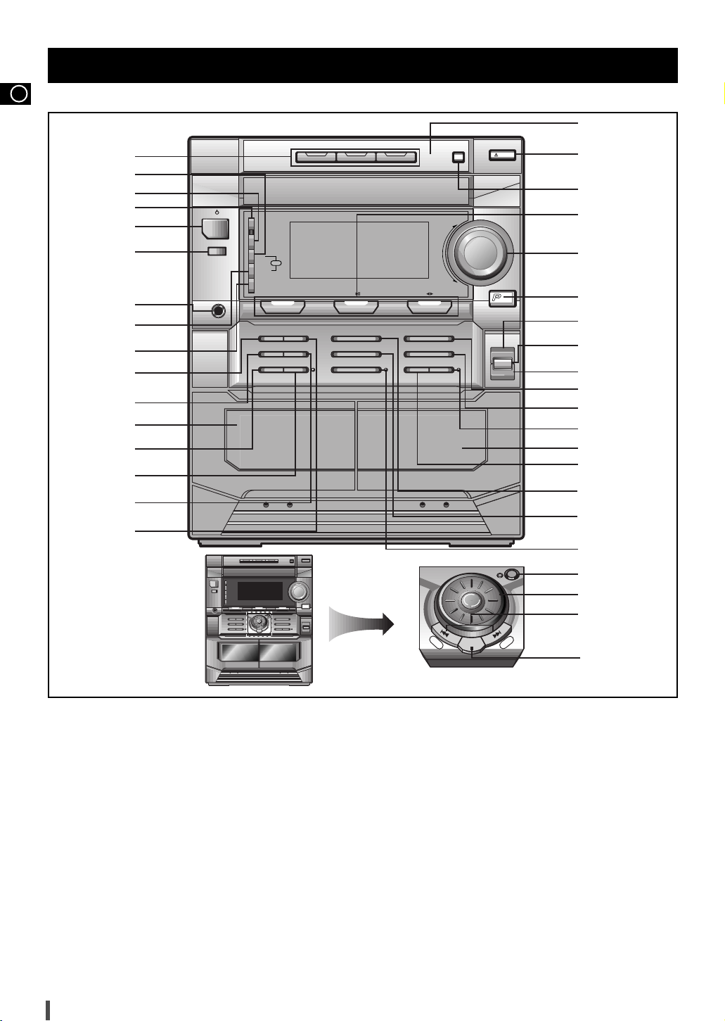
1. Disc Selection Buttons
2. PTY (RDS)
3. Demo
4. Game
5. On/Standby
6. Aux
7. Headphone Jack Connector
8. Display (RDS)
9. Timer/Clock
10. Rev Mode
11. Counter Display (MAX-N73/N72)
Dolby NR (MAX-N75)
12. Cassette Deck 1
13. Dubbing Normal/CD REC/Pause
14. Dubbing High
15 Counter Reset
16. Deck 1/2
17. Preset/Manual or Stop Button
18. CD Track or Radio Station Search (Down/Up)
19. Moving Jog
20. Manual EQ/Enter
21. REC/Pause
22. Preset Memory
23. Mono/ST
24. Shuffle
25. Cassette Deck 2
26. CD Synchro
27. CD Repeat
28. Program
29. 3D Surround
30. EQ
31. S. Bass
32. Power Surround
33. Volume
34. Function Selection Buttons.
35. Disc Change
36. Open/Close
37. Compact Disc Compartment
Front Panel View
Phones
Disc 1 Disc 2 Disc 3
Disc Change
Open/
Close
Game
Demo
Timer/
Clock
Rev Mode Deck 1/2
Counter Reset
Normal
CD REC/Pause
High
Dubbing
Mono/ST
Preset/Memory
REC/Pause
Program
TAPE
Volume
CDTUNER
Band
CD Repeat
Shuffle CD Synchro
S.BASS
ower
Surround
EQ
3D Surround
Aux
On/Standby
+
–
PTY
Display
RDS
Preset/Manual
Manual EQ
/Enter
Down
Up
1
2
3
4
5
6
7
8
9
11
10
12
13
14
15
16
28
29
30
31
32
33
34
35
36
37
27
24
25
26
23
22
21
17
18
19
20

GB
5
Remote Control
1. On/Standby
2. Disc Number Skip
3. Sound Mode
4. Deck 1/2
5. CD Repeat
6. Tape Rewind and Fast-Forward
7. CD Stop
8. Volume Increase
9. Volume Decrease
10. Tuning Mode
11.
CD Track or Radio Station Search
12. CD Play and Pause
13. Deck Stop
14. Deck Play
15. Mono/ST Selection
16. Frequency Band Selection
17. AUX
18. Program/Set
19. Mute
20. Timer On/Off
Power
Timer
On/Off
TAPE
Sound
Mode
Disc Skip
Deck 1/2 Repeat Mono/ST. Tuner
Band
Program
/Set
Aux
Mute
CD
CDCD
VOL.
VOL.
Tuning
Mode
CD
1
2
3
4
5
6
7
8
9
20
19
18
17
16
15
14
13
12
11
10
GB
6
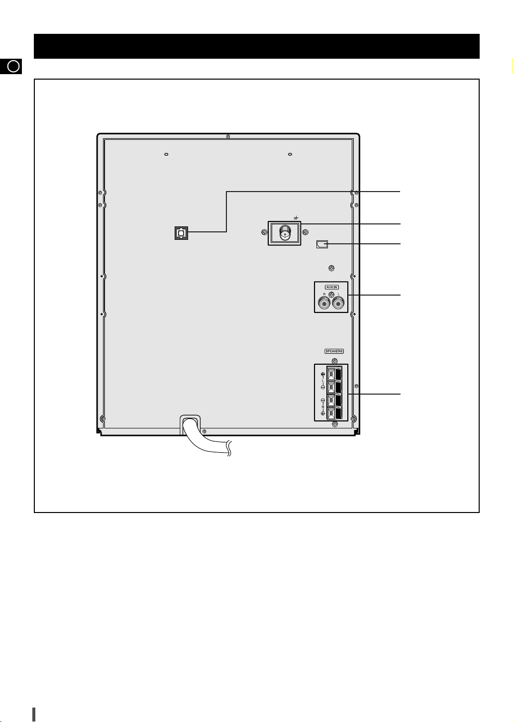
Rear Panel View
1. CD Digital out Jack
2. FM Aerial Connector Terminal
3. AM(MW)/LW Aerial Connector Terminal
4. Aux-Input
5. Loudspeaker Connector Terminal
(IMPEDANCE 6Ω)
AM ANT
DIGITAL OUT
OPTICAL
FM ANT. (75Ω)
1
2
3
4
5

GB
7
The loudspeaker connector terminals are located on the rear
of the system.
There are four terminals on the system:
Two for the left speaker (marked L)
Two for the right speaker (marked R)
To achieve the correct sound quality, connect the:
Red wire to the + terminals
Black wire to the - terminals
To connect a wire to a terminal, push the tab as far as it will go:
To the right on the system
Insert the wire, up to the plastic sheathing, in the hole.
Push the tab back:
To the left on the system, until it clicks into place
To the top on the loudspeaker
Result:
The wire is pinched and held firmly in place.
Repeat the operation for each wire.
To take full advantage of your new mini-compact system, follow
these installation instructions before connecting the unit.
Install the system on a flat, stable surface.
Never place this unit on carpeting.
Never place this unit in an outdoor area.
Maintain an open space of approximately 4 inches (10 cm) on the
sides and rear of the system, for ventilation purposes.
Make sure that you have enough room to open the compact disc
compartment easily.
Place the loudspeakers at a reasonable distance on either side of the
system to ensure good stereo sound.
Direct the loudspeakers towards the listening area.
For optimum performance, make sure that both speakers are placed
at an equal distance above the floor.
Where to Install Your Mini-Compact System
Connecting the Loudspeakers
Disc 1 Disc 2 Disc 3
Disc Change
Open/
Close
Game
Demo
PTY
Display
Timer/
Clock
Rev Mode Deck 1/2
Counter Reset
Normal
CD REC/Pause
High
Dubbing
Mono/ST
Preset/Memory
REC/Pause
Program
TAPE
Volume
CDTUNER
Band
CD Repeat
Shuffle CD Synchro
S.BASS
ower
Surround
EQ
3D Surround
Aux
On/Standby
+
–
RDS
Preset/Manual
Manual EQ /EnterMoving Control
Up
Down
L
R
1
2
3
4
(IMPEDANCE 6Ω)
The main lead must be plugged into an appropriate socket.
Before plugging your system into a main socket, you must check
the voltage.
Plug the main lead (marked AC Cord on the rear of the system) into
an appropriate socket.
Press the On/Standby button to switch your mini-compact system on.
Connecting your System to the Power Supply
1
2
<MAX-N75>
L
R
<MAX-N73>
L
R
<MAX-N72>
GB
8
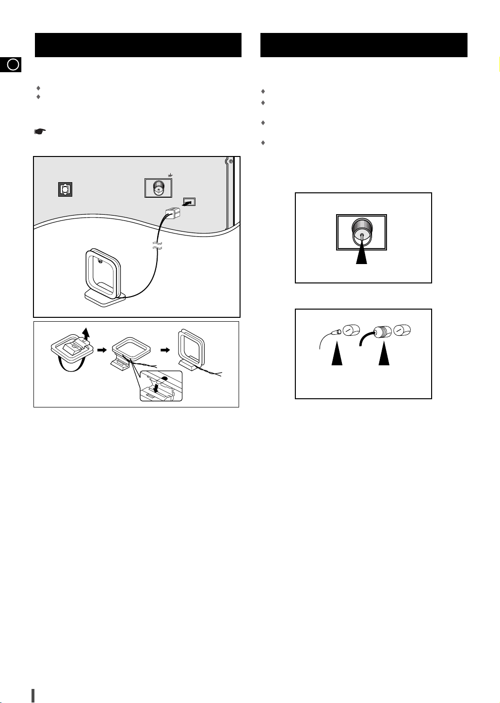
How to connect a COAXIAL TYPE aerial.
Connect a 75Ω antenna to the FM antenna terminal.
Plug the connector on the FM aerial supplied into the coaxial socket
(75Ω) marked FM on the rear of the system.
Follow the instructions given on Page 14 to tune into a radio sta-
tion, and determine the best position for the aerial.
If reception is poor, you may need to install an outdoor aerial.
To do so, connect an outdoor FM aerial to the FM socket on the rear
of the system using a 75Ω coaxial cable (not supplied).
Connecting the FM Aerial
FM AERIAL
(supplied)
75Ω COAXIAL CABLE
(not supplied)
Connecting the AM(MW)/LW Aerial
The AM aerial (for long and medium waves) can be:
Placed on a stable surface
Fixed to the wall (you must first remove the base)
The AM aerial connector terminals are located on the rear of the system and
are marked AM .
To avoid noise interference, check that the loudspeaker wires do
not run close to the aerial wires.
Always keep them at least 2 inches (5 cm) away.
DIGITAL OUT
OPTICAL
FM ANT. (75Ω)
AM ANT.
FM FM
 Loading...