

Samsung MAX-DS530 User Manual
Instruction Manual
THREE-CD CHANGER
DVD MINI-COMPACT
SYSTEM
MAX-DS9250
GB
2
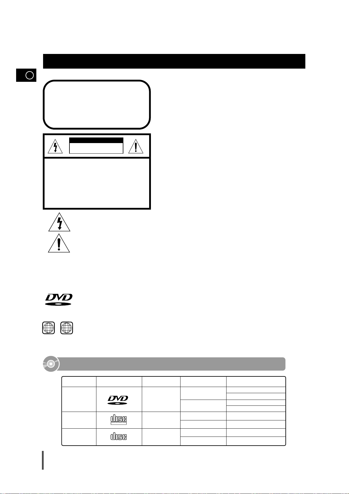
CLASS 1 LASER PRODUCT
This Compact Disc player is classified as a CLASS 1
LASER product.
Use of controls, adjustments or performance of procedures other than those specified herein may result in
hazardous radiation exposure.
CAUTION-INVISIBLE LASER RADIATION
WHEN OPEN AND INTER LOCKS
DEFEA TED, AVOID EXPOSURE TO
BEAM.
This symbol indicates that dangerous voltage which can cause electric shock is present inside this unit.
This symbol alerts you to important operating and maintenance instructions accompanying the unit.
WARNING: To reduce the risk of fire or electric shock, do not expose this appliance to rain or
moisture.
CAUTION: TO PREVENT ELECTRIC SHOCK, MATCH WIDE BLADE OF PLUG TO WIDE SLOT,
FULLY INSERT.
CLASS 1 LASER PRODUCT
KLASSE 1 LASER PRODUKT
LUOKAN 1 LASER LAITE
KLASS 1 LASER APPARAT
PRODUCTO LASER CLASE 1
RISK OF ELECTRIC SHOCK.
DO NOT OPEN
CAUTION:
TO REDUCE THE RISK OF ELECTRIC
SHOCK, DO NOT REMOVE REAR COVER.
NO USER SERVICEABLE PARTS INSIDE.
REFER SERVICING TO QUALIFIED
SERVICE PERSONNEL.
CAUTION
Safety Warnings
DVD (Digital Versatile Disc) offers fantastic audio and video, thanks to Dolby Digital
surround sound and MPEG-2 video compression technology. Now you can enjoy these
realistic effects in the home, as if you were in a movie theater or concert hall.
V I D E O
DVD players and the discs are coded by region. These regional codes must match in order
for the disc to play. If the codes do not match, the disc will not play.
The Region Number for this player is given on the rear panel of the player.
(Your DVD player will only play DVDs that are labeled with identical region codes.)
1 6
~
Mark (Logo)
Audio + Video
DVD
VIDEO-CD
AUDIO-CD
12cm
Approx. 240 min. (single-sided)
Approx. 480 min. (double-sided)
Approx. 80 min. (single-sided)
Approx. 160 min. (double-sided)
74 min.
20 min.
74 min.
20 min.
8cm
12cm
8cm
12cm
8cm
Audio + Video
Audio
Recorded Signals
Disc Type Disc Size Max. Playing Time
Playable Discs
V I D E O
COMPACT
DIGITAL VIDEO
COMPACT
DIGITAL AUDIO

GB
Press Push Important Note
Symbols
3
Contents
S
AFETYWARNINGS
................................................................ 2
I
NSTALLINGYOUR
M
INI
-C
OMPACTSYSTEM
Front Panel View .................................................................. 4
Rear Panel View .................................................................. 5
Remote Control .................................................................... 6
Where to Install Your Mini-Compact System ........................ 8
Connecting your System to the Power Supply...................... 8
Connecting the Loudspeakers .............................................. 8
Connection of the subwoofer (optional) ................................ 8
Connection of the TV monitor and VCR (optional) ................ 9
DVD/CD Digital Out Jack ...................................................... 9
Connecting to an External Source.......................................... 9
Connection for better sound ................................................ 10
Connecting the AM (MW) Aerial............................................ 11
Connecting the FM Aerial .................................................... 11
Connecting the SW Aerial (option)........................................ 11
Demo/Dimmer function ........................................................ 12
Setting the Clock.................................................................. 12
CD-P
LAYER
Playing a Disc ...................................................................... 13
Selecting a Disc in the CD changer...................................... 13
DVD Playback ...................................................................... 13
Forward/Reverse Searching ................................................ 14
Slow Playback/Checking the Remaining Time...................... 15
Repeat Playback .................................................................. 15
Using Disc Menu/Title .......................................................... 16
Program Playback................................................................ 16
Selecting the Audio Language/Subtitle Language ................ 17
Various DVD Functions........................................................ 18
MP3 Playback ...................................................................... 18
System Setup ...................................................................... 20
Setting up the Language Features ...................................... 22
T
UNER
Searching for and Storing the Radio Stations .................... 22
Selecting a Stored Station.................................................... 23
Improving Radio Reception.................................................. 23
T
APEDECK
Listening to a Cassette ........................................................ 24
CD Synchro Record Feature................................................ 24
Recording a Compact Disc .................................................. 24
Recording a Radio Programme............................................ 25
Copying a Cassette (Dubbing) ............................................ 25
Tape Counter........................................................................ 25
Selecting the Cassette Playback Mode (Deck 2 Only) ........ 25
O
THER
F
UNCTIONS
Timer Function...................................................................... 26
Cancelling the Timer ............................................................ 26
Mute Function ...................................................................... 27
Power Sound Function ........................................................ 27
Selecting an Equalizer Preset .............................................. 27
3D Sound Function .............................................................. 27
Setting the System to Switch off Automatically .................... 28
Super Bass Sound .............................................................. 28
Connecting Headphones...................................................... 28
Microphone Function (option) .............................................. 28
R
ECOMMENDATIONS FOR
U
SE
Safety Precautions .............................................................. 29
Cleaning Your Mini-Compact System .................................. 29
Precautions When Using Compact Discs ............................ 29
Precautions When Using Audio Cassettes .......................... 30
Before Contacting the After-Sales Service .......................... 30
Technical Specifications ...................................................... 31
Reference ............................................................................ 32
Thank you for buying this
SAMSUNG mini-compact system.
Please take time to read these instructions.
They will allow you to operate your
system with ease and take full advantage
of its features.
GB
4
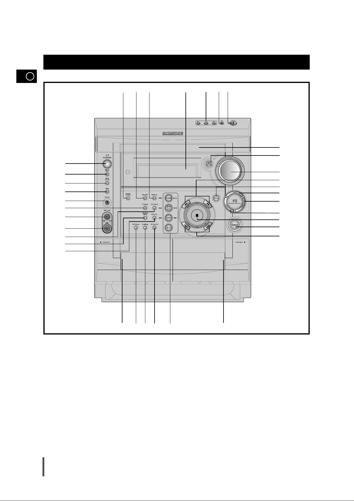
Front Panel View
2930313233
1
2
3
4
5
6
7
8
9
11
10
12
13 14 15 16 17
18
19
20
21
23
22
24
25
26
27
28
3435
1. Standby/On
2. Timer/Clock
3. Timer On/Off
4. Sleep
5. Headphone Jack Connector
6. Program button
7. MIC Level (option)
8. MIC Jack(option)
9. CD Repeat
10. Reverse Mode
11. Deck 1/2
12. Cassette Deck 1
13. Record/Pause
14. TAPE Normal Dubbing
15. CD Synchro Recording
16. Function Selection buttons
17. Cassette Deck 2
18. Skip Function buttons
19. Super Bass
20. Stop button
21. EQ Preset Classic
22. EQ Preset Rock
23. EQ Preset Pop
24. Enter
25. Search Function buttons
26. Volume
27. 3D SOUND
28. Compact Disc Compartment
29. CD Open/Close
30. Disc Change
31. Disc Selection buttons
32. Window Display
33. Memory Function
34. FM Mono/Stereo
35. Demo/Dimmer
GB
5
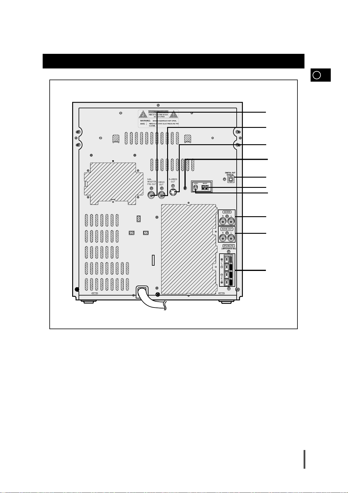
Rear Panel View
1. SUB WOOFER PRE OUT
2. VIDEO OUT
3. S-VIDEO OUT
4. SW AERIAL CONNECTOR TERMINAL
5. DIGITAL OUT JACK
6. AM AERIAL CONNECTOR TERMINAL
7. FM AERIAL CONNECTOR TERMINAL
8. AUX INPUT
9. AUDIO OUT
10. LOUDSPEAKER CONNECTOR TERMINALS
1
2
3
5
4
6
7
8
9
10
DVD
Timer On
Power Sound
MO/ST
3D.Sound
Deck 1/2
Counter Reset
S. Bass EQ
Menu
DVD/CD/TUNER
Tuning
Enter
Volume
Down Up
Sleep
Disc Skip Open/Close
TUNER
Band
AUX Mute
TAPE
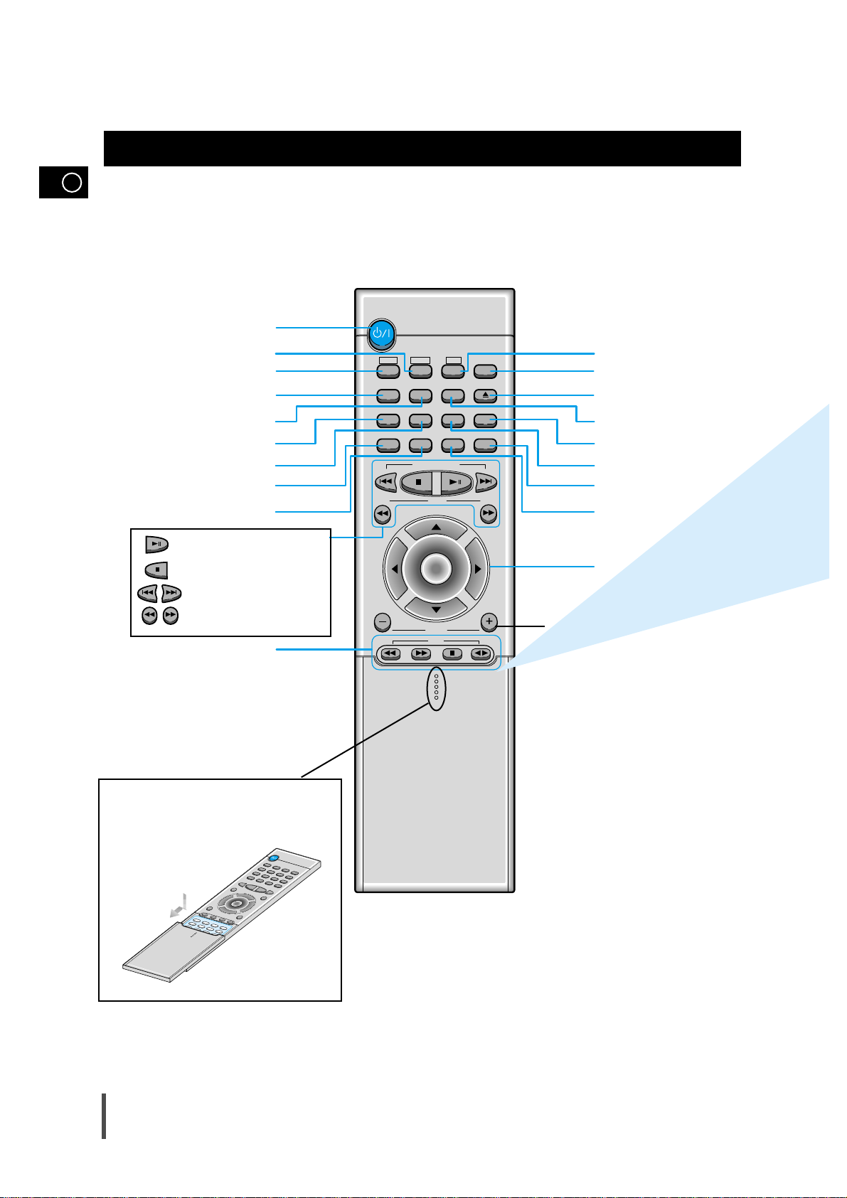
Remote Control
Standby/On button
TUNER(Band) button
DVD button
Timer On button
Power Sound button
3D.Sound button
Deck 1/2
button
Counter Reset button
TAPE Function buttons
MO/ST(mono/stereo) button
To open the cover of the remote
control, push the top of the cover,
then slide downward.
AUX button
Mute button
EQ button
S.Bass button
Sleep button
Menu button
Direction/Enter button
Disc Number Skip
button
Open/Close button
Volume Control buttons
Speaker output volume control
Play/Pause button
Stop button
Tuning Preset/CD Skip button
Tuning Up/Down/CD Search button
GB
6
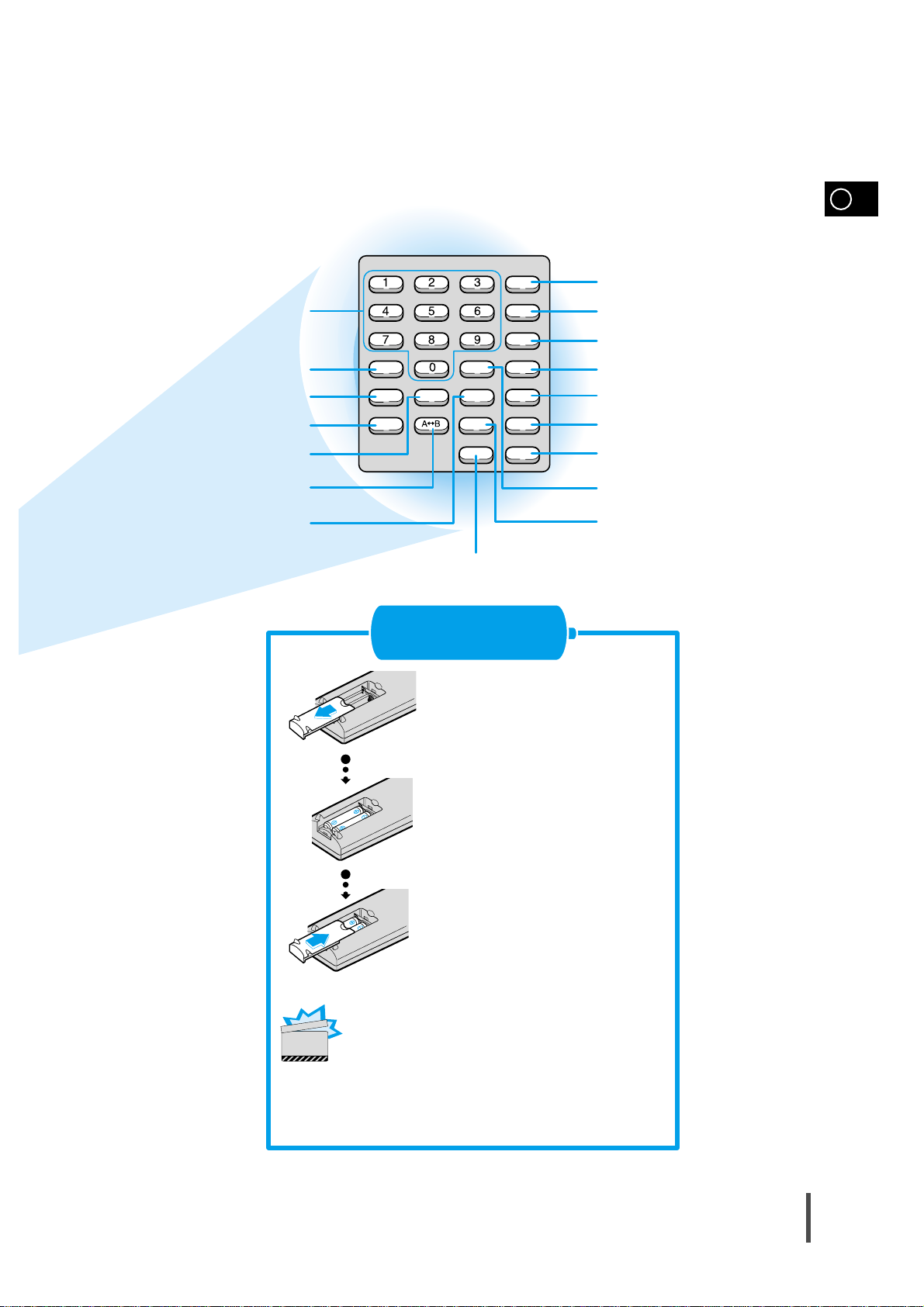
Setup
Title
Return
Subtitle
Clear
Display
Step
Program
Audio
Go To
Zoom
Repeat
Angle
Remain
Repeat
Slow
GB
7
Remove the battery cover on
the back of the remote by
pressing down and sliding the
cover in the direction of the
arrow.
Insert Remote Batteries
1
Insert two 1.5V AAAbatteries,
paying attention to the correct
polarities (+ and –).
2
Replace the battery cover.
3
Slow button
Setup button
Title button
Return button
Subtitle button
Clear button
Display button
Step button
Audio button
Go To button
Number(0~9) buttons
Remain button
Angle button
Repeat button
Zoom button
Repeat A
↔B button
Program button
Follow these precautions to avoid leaking or cracking cells:
•
Place batteries in the remote control so they match the
polarity:(+) to (+)and (–)to (–).
•
Use the correct type of batteries.Batteries that look similar
may differ in voltage.
•
Always replace both batteries at the same time.
•
Do not expose batteries to heat or flame.
CAUTION
GB
8
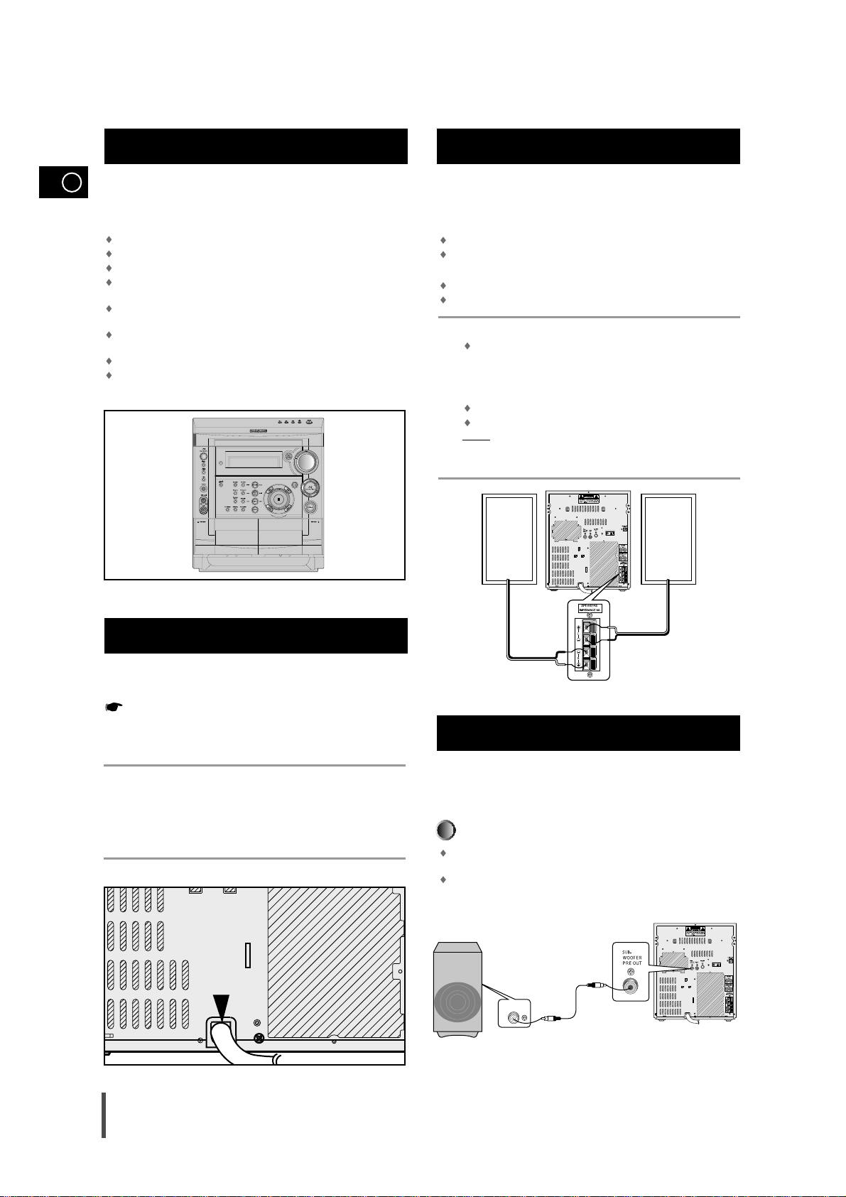
To take full advantage of your new mini-compact system, follow these installation instructions before connecting the unit.
Install the system on a flat, stable surface.
Never place this unit on carpeting.
Never place this unit in an outdoor area.
Maintain an open space of approximately 6 inches (15 cm) on the
sides and rear of the system, for ventilation purposes.
Make sure that you have enough room to open the compact disc
compartment easily.
Place the loudspeakers at a reasonable distance on either side of
the system to ensure good stereo sound.
Direct the loudspeakers towards the listening area.
For optimum performance, make sure that both speakers are placed
at an equal distance above the floor.
The main lead must be plugged into an appropriate socket.
Before plugging your system into a main socket, you must check
the voltage setting. If the voltage of the socket does not correspond to the setting on the rear of the unit, you may seriously
damage your system.
Check the position of the voltage selector on the rear of the system.
Plug the main lead (marked AC Cord on the rear of the system) into
an appropriate socket.
Press the On/Standby button to switch your mini-compact system on.
The loudspeaker connector terminals are located on the rear
of the system.
There are four terminals on the system:
Two for the left speaker (marked L)
Two for the right speaker (marked R)
To achieve the correct sound quality, connect the:
Red wire to the + terminals
Black wire to the
–
terminals
To connect a wire to a terminal, push the tab as far as it will go:
To the right on the system
Insert the wire, up to the plastic sheathing, in the hole.
Push the tab back:
To the left on the system, until it clicks into place
To the top on the loudspeaker
Result:
The wire is pinched and held firmly in place.
Repeat the operation for each wire.
The subwoofer generates low-pitched tones.
(Ex. Explosion, the sound of spacecraft flying, the sound of pon-
dering, etc.)
Connect the subwoofer (not supplied)
Connect the subwoofer cord to the SUBWOOFER IN and SUB
WOOFER PRE OUT terminal.
Plug the AC Cord on the rear of the SUBWOOFER into an appropriate socket.
Where to Install Your Mini-Compact System
Connecting your System to the Power Supply
Connecting the Loudspeakers
Connection of the subwoofer (optional)
1
2
3
4
1
2
3
SUBWOOFER
IN
(+) (—) (+) (—)
()
GB
9
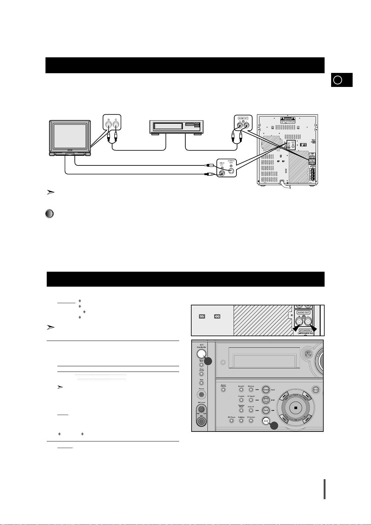
The following show examples of connections commonly used to connect the DVD player with a External Source.
(Example : TV, VCR, DAT CD-RW, etc)
• When S-VIDEO is connected, S-VIDEO has priority.
Connection of the TV monitor and VCR (optional)
LINE IN
TV monitor VCR
Audio cord Audio cord
LINE INLINE OUT
S-Video
Composite video (Supplied)
This unit can output DVD/CD digital sound signals through this jack. Use an optical cable to connect
digital audio equipment. (DAT deck, MD recorder, etc.).
Remove the dust cap (1) from the DVD/CD DIGITAL OUT jack. Then, connect an optical cable plug to
the DVD/CD DIGITAL OUT jack.
When the DVD/CD DIGITAL OUT jack is not being used
Attach the supplied dust cap.
DVD/CD Digital Out Jack
Connecting to an External Source
The auxiliary input can be used to take advantage of the sound quality
of your mini-compact system when listening to other sources.
Examples
: A television
A video disc player
A DAT or DCC cassette player
A Hi-Fi stereo video cassette recorder
To connect the external source, the source must have an audio
output. In addition, you need an RCA connection cable.
Set the system to standby mode and disconnect it and the external
source from the main.
Connect the audio cable to the rear of the mini-compact system.
Connect the... To the connector marked...
Red jack R (right)
White jack L (left)
For optimum sound quality, do not invert the right and left channels.
Plug the system back into the main socket and press Standby/On to
switch it on.
Select the AUX source by pressing AUX on the front panel.
Result
: AUX is displayed.
Switch the external source on.
Adjust the volume and balance as required:
Volume Equalizer
Example
: You can watch a film and take advantage of stereo sound
provided that the original sound track is in stereo, (as if you
were in a cinema).
1
2
3
4
5
6
4
3
GB
10
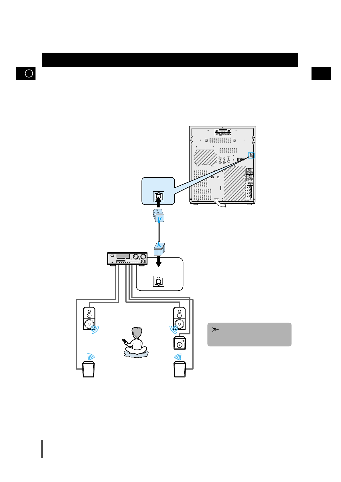
Connecting to an amplifier with Dolby Pro Logic support.
Connection for better sound
OPTICAL INPUT
DIGITAL OUT
OPTICAL
While playing a DTS disc, no sound is
reproduced. In this case, connect to an
external amplifier.
GB
11
11
GB
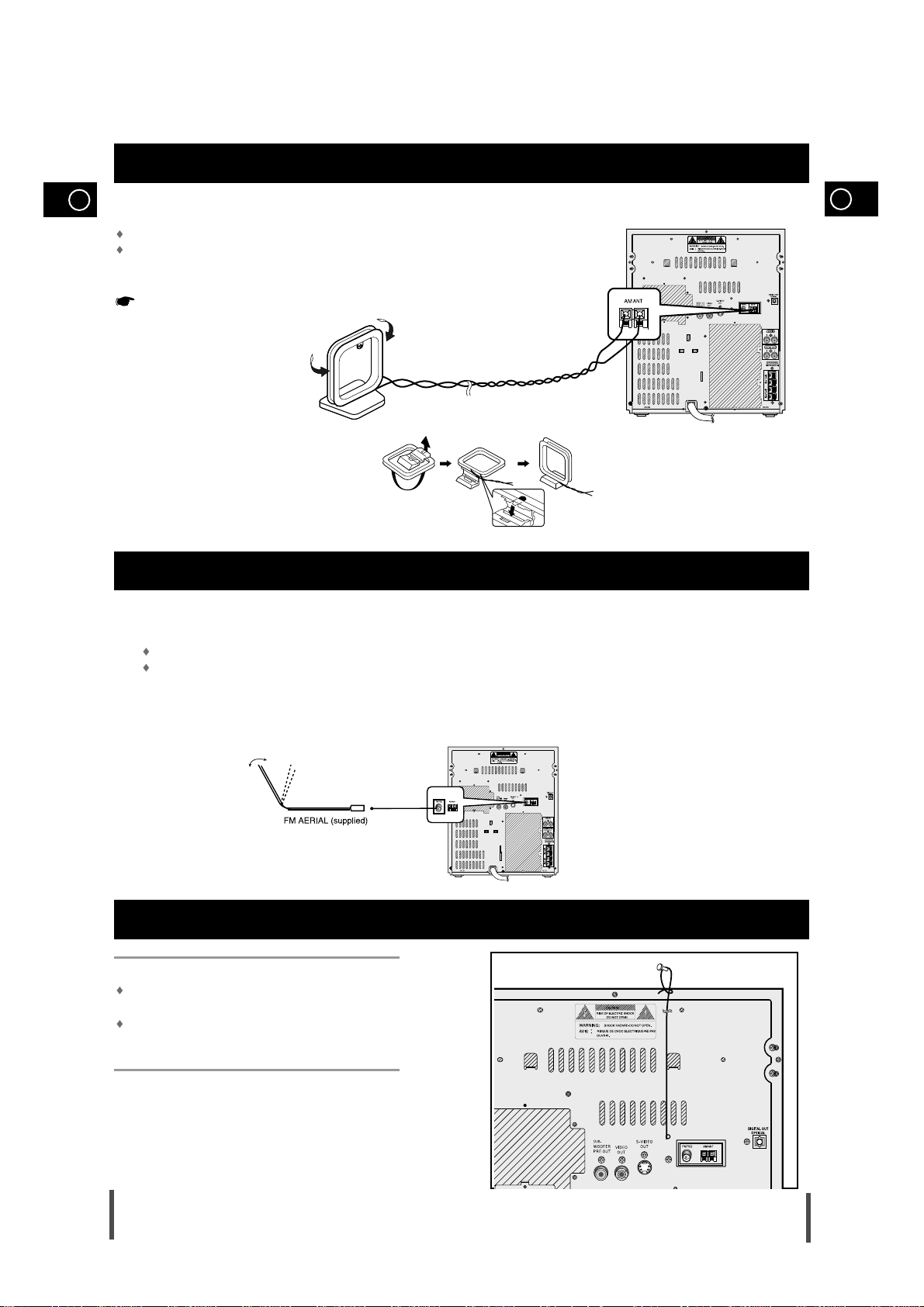
The AM aerial (for long and medium waves) can be:
Placed on a stable surface
Fixed to the wall (you must first remove the base)
The AM aerial connector terminals are located on the rear of the system and are marked AM .
To avoid noise interference, check that the loudspeaker wires do not run close to the aerial wires.
Always keep them at least 2 inches (5 cm) away.
Connecting the AM (MW) Aerial
How to connect a SCREW TYPE aerial.
The FM aerial connector terminals are located on the rear of the system and marked FM (75Ω).
Spread the T.form FM aerial out and attach the ends to a wall,
in the position providing the best reception.
Connecting the FM Aerial
How to connect a WIRE TYPE aerial.
Spread the SW aerial out and attach the ends to a wall, in
the position providing the best reception.
If reception is poor (e.g. distance from transmitter too
great, walls blocking the radio waves, etc.), install an outdoor aerial.
Connecting the SW Aerial
 Loading...