

5-1 High Voltage Transformer
1. Remove connectors from the transformer terminals
and check continuity.
2. Normal resistance readings should be as follows:
Secondary ..........................Approx. 131.5W
Filament .............................Approx. 0W
Primary...............................Approx. 2.29W
(Room temperature = 20ûC)
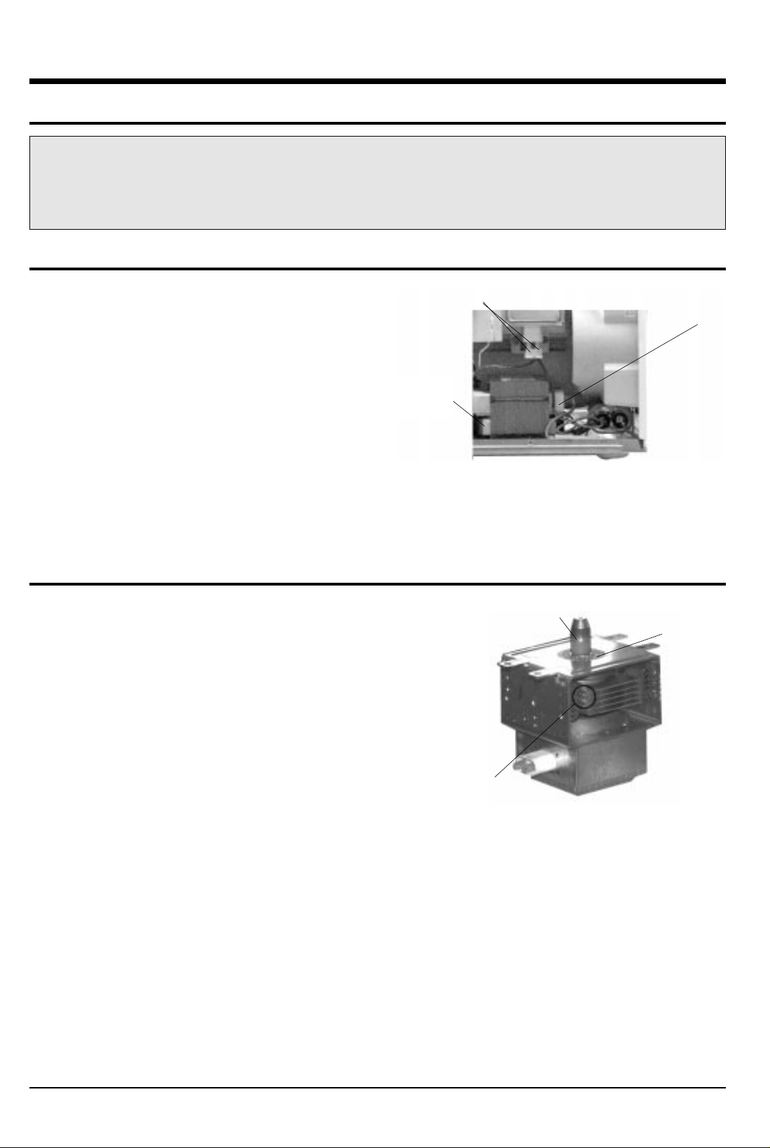
5-2 Magnetron
1. Continuity checks can only indicate an open filament or a
shorted magnetron. To diagnose an open filament or
shorted magnetron.
2. Isolate the magnetron from the circuit by disconnecting its
leads.
3. A continuity check across the magnetron filament
terminals should indicate one ohm or less.
4. A continuity check between each filament terminal and the
magnetron case should read "open".
Magnetron Antenna
Gasket Plate
Cooling Fins
5. Alignment and Adjustments
Samsung Electronics 5-1
PRECAUTION
1. High voltage is present at the high voltage terminal of the high voltage transformer during any cook cycle.
2. It is neither necessary nor advisable to attempt measurement of the high voltage.
3. Before touching any oven components, or wiring, always unplug the oven from its power source and discharge the high voltage
capacitor.
Filament Terminals
Secondary Terminal
Primary
Terminals
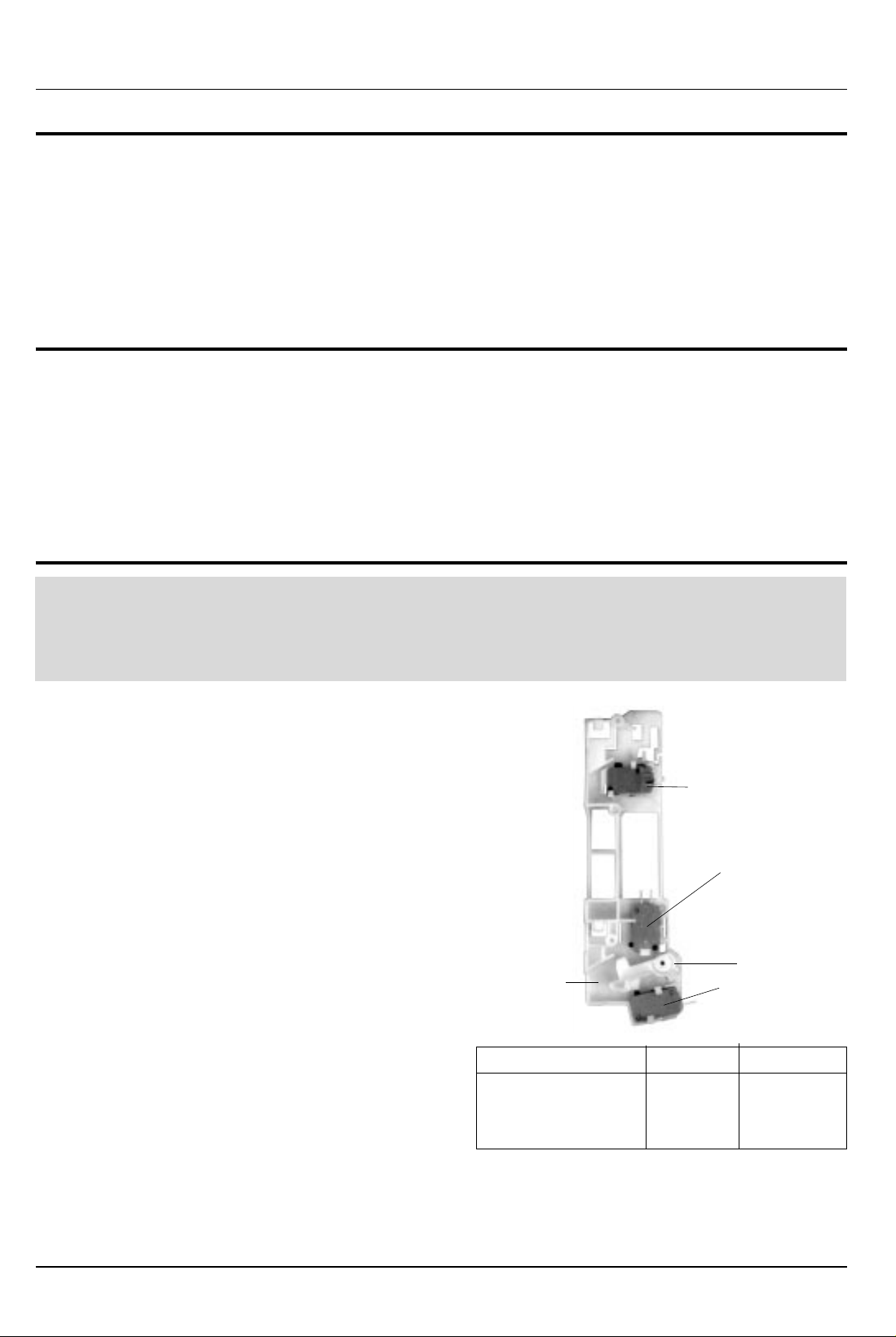
5-5 Adjustment of Primary Switch, Secondary Swithc and Monitor Switch
1. When mounting Primary switch and Interlock Monitor
switch to Latch Body, consult the figure below.
2. NOTE: No specific adjustment during installation of
Primary
switch and Monitor switch to the latch body is
necessary.
3. When mounting the Latch Body to the oven assembly,
adjust to the Latch Body by moving it so that the oven
door will not have any play. Check for play in the door
by pulling the door assembly. Make sure that the latch
keys move smoothly after adjustment is completed.
Completely tighten the screws holding the Latch Body
to the oven assembly.
4. Reconnect to Monitor switch and check the continuity
of the monitor circuit and all latch switches again by
following the components test procedures.
5. Confirm that the gap between the switch housing and
the switch actuator is no more than 0.5mm when door
is closed.
5-2 Samsung Electronics
Precaution
For continued protection against radiation hazard, replace parts in accordance with the wiring diagram and be sure to use the correct
part number for the following switches.: Primary and secondary interlock switches and the interlock monitor switch all together. Then
follow the adjustment procedures below. After repair and adjustment, be sure to check the continuity of all interlock switches and the
interlock monitor switch.
Alignment and Adjustments
5-3 High Voltage Capacitor
1. Check continuity of the capacitor with meter set at the highest ohm scale.
2. Once the capacitor is charged, a normal capacitor shows continuity for a short time, and then indicates
10MW.
3. A shorted capacitor will show continuous continuity.
4. An open capacitor will show constant 10MW.
5. Resistance between each terminal and chassis should read infinite.
5-4 High Voltage Diode
1. Isolate the diode from the circuit by disconnecting its leads.
2. With the ohm-meter set at the highest resistance scale, measure the resistance across the diode terminals.
Reverse the meter leads and read the resistance. A meter with 6V, 9V or higher voltage batteries should be
used to check the front-to back resistance of the diode, otherwise an infinite resistance may be read in both
directions. The resistance of a normal diode will be infinite in one direction and several hundred KW in the
other direction.
Door Open Door Closed
Primary switch ¥ 0
Monitor switch (COM-NC) 0 ¥
Secondary S/W ¥ 0
Primary Interlock Switch
Lever Door
Body Latch
Secondary
Switch
Interlock Monitor
Switch

Samsung Electronics 5-3
5-6 Output Power of Magnetron
The output power of the magnetron can be measured by performing a water temperature rise test.
Equipment needed
* Two 1-liter cylindrical borosilicate glass vessel (Outside diameter of 190mm)
* One glass thermometer with mercury column
NOTE: Check line voltage under load. Low voltage will lower the magnetron output. Make all temperature
and time tests with accurate equipment.
1. Fill the one liter glass vessel with one liter of water.
2. Stir water in glass vessel with thermometer and record glass vessel's temperature as T1. (10±1ûC)
3. After moving the water into another glass vessel, place it on the center of the cooking tray. Set the oven to
high power
and operate for 52.3 seconds exactly. (2 seconds included as a holding time of magnetron oscillation)
4. When heating is finished, stir the water again with the thermometer and measure the temperature rise as
T2.
5. Subtract R1 from T2. This will give you the water temperature rise. (DT)
6. The output power is obtained by the following formula;
52.3 : Heating Time (sec) * Output (W) = 100 x DT
4.187 x 1000 x DT 4.187 : Coefficient for Water
Output Power = 1000 : Water (cc)
52.3 DT : Temperature Rise (T2-T1)
7. Normal temperature rise for this model is 9ûC to 11ûC at 'HIGH'.
NOTE 1: Variations or errors in the test procedure will cause a variance in the temperature rise. Additional
power test should be made if temperature rise is marginal.
NOTE 2: Output power in watts is computed by multiplying the temperature rise (step E) by a power factor
of 91 in case of centigrade temperature.
5-7 Microwave Heat Distribution - Heat Evenness
The microwave heat distribution can be checked indirectly by measuring the water temperature risen at certain
positions in the oven :
1. Prepare five beakers made of 'Pyrex', having 100 milliliters capacity each.
2. Measure exactly 100milliliters off water load with a measuring cylinder and pour it into each beaker.
3. Measure the temperature of each water load.
(Readings shall be taken to the first place of decimals.)
4. Put each beaker in place on the cooking tray as illustrated in figure
below and start heating.
5. After heating for 2 minutes, measure the temperatures of water in each
beaker.
6. Microwave heat distribution rate can be caicviated as follows :
Minimum
Temperature Rise
Heat Distribution = X 100(%)
Maximum
Temperature Rise
The result should exceed 65%.
D
D
D/4
D/4
D/4
D/4
Cooking Tray
Beaker
CAUTION
MICROWAVE RADIATION
PERSONNEL SHOULD NOT ALLOW EXPOSWRE TO MICROWAVE RADIATION FROM MICROWAVE GENERATOR OR OTHER
PARTS CONDUCTING MICROWAVE ENERGY.
Alignment and Adjustments

5-4 Samsung Electronics
1) Pour 275¡¾15cc of 20¡¾5¡É ( 68¡¾9¢µ ) water in
a beaker which is graduated to 600cc, and place
the beaker in the center of the oven.
2) Start to operate the oven and measure the
leakage by using a microwave energy survey
meter.
3) Set survey meter with dual ranges to 2,450MHz.
4) When measuring the leakage, always use the 2
inch spacer cone with the probe. Hold the probe
perpendicular to the cabinet door. Place the
spacer cone of the probe on the door and/or
cabinet door seam and move along the seam, the
door viewing window and the exhaust openings
moving the probe in a clockwise direction at a rate of 1 inch/sec. If the leakage testing of the cabinet door
seam is taken near a corner of the door, keep the probe perpendicular to the areas making sure that the
probe end at the base of the cone does not get closer than 2 inches to any metal. If it gets closer than 2
inches, erroneous readings may result.
5) Measured leakage must be less than 4mW/cm2, after repair or adjustment.
Alignment and Adjustments
800w
M736
120w
240w
400w
560w
0
1
2
3
4
5
6
7
8
9
10
20
30
40
50
60
5-13 Leakage Measuring Procedure
5-10 Procedure for Measurement of Microwave Energy Leakage
5-12Note on Measurement
5-11 Check for Microwave Leakage
5-13-1 Record keeping and notification after measurement
1) After adjustment and repair of a radiarion preventing device, make a repair record for the measured
values, and keep the data.
2) If the radiation leakage is more than 4 mW/§² after determining that all parts are in good condition,
functioning properly and the identical parts are replaced as listed in this manual notift that fact to ;
CENTRAL SERVICE CENTER
5-13-2 At least once a year have the microwave energy survey meter checked for accuracy by its
manufacturer.
1. Remove the outer panel.
2. Pour 275±15cc of 20±5ûC(68±9ûF) water in a
beaker which is graduated to 600cc, and
place the beaker in the center of the oven.
3. Start the oven at the highest power level.
4. Set survey meter dual ranges to 2,450MHz.
5. Using the survey meter and spacer cone as
described above, measure arnear the
opening of magnetron, the surface of the air
guide and the surface of the wave guide as
shown in the following photo.( but avoid the
high voltage components.) The neading
should be less than 4mW/cm2.
1) Do not exceed the limited scale.
2) The test probe must be held on the grip of the handle, otherwise a false reading may result when the
operator's hand is between the handle and the probe.
3) When high leakage is suspected, do not move the probe horizontally along the oven surface; this may
cause damage to the probe.
4) Follow the recommendation of the manufacturer of the microwave energy survey meter.
Maximum allowable leakage is 5mW/cm2.
4mW/cm2is used to allow for measurement and meter accuracy
 Loading...