

SAMSUNG LXB341TLMUXAA Service Manual
COLOR MONITOR
SyncMaster 320TFT/520TFT
Manual
SERVICE
COLOR MONITOR CONTENTS
**
1. Precautions
2. Reference Information
3. Product Specifications
4. Operating Instructions
5. Disassembly & Reassembly
6. Troubleshooting
7. Exploded View & Parts List
8. Block Diagram
9. Electrical Parts List
10. PCB Diagrams
11. Wiring Diagram
12. Schematic Diagrams

Samsung Electronics Co., Ltd. July 1998
Printed in Korea
Code No.: BN68-60012A
1-1-1 Warnings
1. For continued safety, do not attempt to modify the
circuit board.
2. Disconnect the AC power and DC Power Jack
before servicing.
3. When the chassis is operating, semiconductor
heatsinks are potential shock hazards.
1-1-2 Servicing the LCD Monitor
1. When servicing the LCD Monitor, remove the static
charge by connecting a 10k ohm resistor in series
with an insulated wire (such as a test probe)
between the chassis and the anode lead.
(Disconnect the AC line cord from the AC outlet.)
2. It is essential that service technicians have an
accurate voltage meter available at all times. Check
the calibration of this meter periodically.
1-1-3 Fire and Shock Hazard
Before returning the monitor to the user, perform the
following safety checks:
1. Inspect each lead dress to make certain that the
leads are not pinched or that hardware is not
lodged between the chassis and other metal parts in
the monitor.
2. Inspect all protective devices such as nonmetallic
control knobs, insulating materials, cabinet backs,
adjustment and compartment covers or shields,
isolation resistor-capacitor networks, mechanical
insulators, etc.
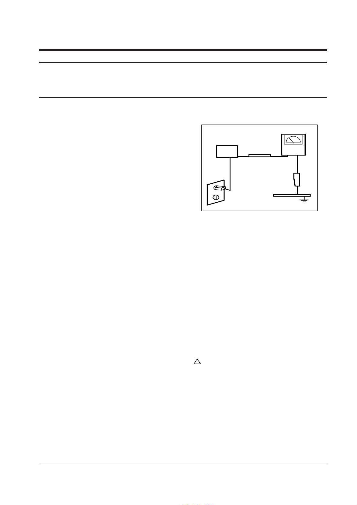
3. Leakage Current Hot Check (Figure 1-1): WARNING:
Do not use an isolation transformer during this test.
Use a leakage current tester or a metering system
that complies with American National Standards
Institute (
ANSI C101.1, Leakage Current for
Appliances), and Underwriters Laboratories (UL
Publication UL1410, 59.7).
Figure 1-1. Leakage Current Test Circuit
4. With the unit completely reassembled, plug the AC
line cord directly into a 120V AC outlet. With the
unitÕs AC switch first in the ON position and then
OFF, measure the current between a known earth
ground (metal water pipe, conduit, etc.) and all
exposed metal parts, including: metal cabinets,
screwheads and control shafts. The current
measured should not exceed 0.5 milliamp. Reverse
the power-plug prongs in the AC outlet and repeat
the test.
1-1-4 Product Safety Notices
Some electrical and mechanical parts have special
safety-related characteristics which are often not
evident from visual inspection. The protection they give
may not be obtained by replacing them with
components rated for higher voltage, wattage, etc. Parts
that have special safety characteristics are identified by
on schematics and parts lists. A substitute
replacement that does not have the same safety
characteristics as the recommended replacement part
might create shock, fire and / or other hazards. Product
safety is under review continuously and new
instructions are issued whenever appropriate.
SyncMaster 320TFT/520TFT 1-1
1 Precautions
Follow these safety, servicing and ESD precautions to prevent damage and to protect against potential hazards such as
electrical shock.
1-1 Safety Precautions
DEVICE
UNDER
TEST
TEST ALL
EXPOSED METAL
SURFACES
(READING SHOULD
NOT BE ABOVE 0.5mA)
LEAKAGE
CURRENT
TESTER
2-WIRE CORD
ALSO TEST WITH
PLUG REVERSED
(USING AC ADAPTER
PLUG AS REQUIRED)
EARTH
GROUND
!

1-2-1 General Servicing Precautions
1. Always unplug the unitÕs AC power cord from the
AC power source and disconnect the DC Power
Jack before attempting to:
(a) remove or reinstall any component or assembly,
(b) disconnect PCB plugs or connectors, (c) connect
a test component in parallel with an electrolytic
capacitor.
2. Some components are raised above the printed
circuit board for safety. An insulation tube or tape
is sometimes used. The internal wiring is
sometimes clamped to prevent contact with
thermally hot components. Reinstall all such
elements to their original position.
3. After servicing, always check that the screws,
components and wiring have been correctly
reinstalled. Make sure that the area around the
serviced part has not been damaged.
1. Immediately before handling any semiconductor
components or assemblies, drain the electrostatic
charge from your body by touching a known earth
ground. Alternatively, wear a discharging wriststrap device. To avoid a shock hazard, be sure to
remove the wrist strap before applying power to
the monitor.
2. After removing an ESD-equipped assembly, place it
on a conductive surface such as aluminum foil to
prevent accumulation of an electrostatic charge.
3. Do not use freon-propelled chemicals. These can
generate electrical charges sufficient to damage
ESDs.
4. Use only a grounded-tip soldering iron to solder or
desolder ESDs.
5. Use only an anti-static solder removal device. Some
solder removal devices not classified as Òanti-staticÓ
can generate electrical charges sufficient to damage
ESDs.
4. Check the insulation between the blades of the AC
plug and accessible conductive parts (examples:
metal panels, input terminals and earphone jacks).
5. Insulation Checking Procedure: Disconnect the
power cord from the AC source and turn the power
switch ON. Connect an insulation resistance meter
(500 V) to the blades of the AC plug.
The insulation resistance between each blade of the
AC plug and accessible conductive parts (see
above) should be greater than 1 megohm.
6. Always connect a test instrumentÕs ground lead to
the instrument chassis ground before connecting the
positive lead; always remove the instrumentÕs
ground lead last.
6. Do not remove a replacement ESD from its
protective package until you are ready to install it.
Most replacement ESDs are packaged with leads
that are electrically shorted together by conductive
foam, aluminum foil or other conductive materials.
7. Immediately before removing the protective
material from the leads of a replacement ESD,
touch the protective material to the chassis or
circuit assembly into which the device will be
installed.
Caution: Be sure no power is applied to the
chassis or circuit and observe all
other safety precautions.
8. Minimize body motions when handling
unpackaged replacement ESDs. Motions such as
brushing clothes together, or lifting your foot from
a carpeted floor can generate enough static
electricity to damage an ESD.
1 Precautions
1-2 SyncMaster 320TFT/520TFT
1-3 Electrostatically Sensitive Devices (ESD) Precautions
Some semiconductor (solid state) devices can be easily damaged by static electricity. Such components are commonly
called Electrostatically Sensitive Devices (ESD). Examples of typical ESD devices are integrated circuits and some fieldeffect transistors. The following techniques will reduce the incidence of component damage caused by static electricity.
1-2 Servicing Precautions
WARNING: An electrolytic capacitor installed with the wrong polarity might explode.
Caution: Before servicing units covered by this service manual, read and follow the Safety Precautions
section of this manual.
Note: If unforeseen circumstances create conflict between the following servicing precautions and any of the
safety precautions, always follow the safety precautions.
SyncMaster 320TFT/520TFT 2-1
2 Reference Information
2-1 List of Abbreviations, Symbols and Acronyms
2-1-1 Abbreviations
Abbreviation Definition Abbreviation Definition
AUTO_MENB AUTO ENABLE (NEG.)
AUTO_SOG SINK ON GREEN ENABLE
BL_EN LCD PANEL BACK LIGHT ENABLE
BRIGHT BRIGHTNESS CONTROL
DAB(7:0) BLUE COLOR DATA (ODD) FROM IC305
DAG(7:0) GREEN COLOR DATA (ODD) FROM IC305
DAR(7:0) RED COLOR DATA (ODD) FROM IC305
DBB(7:0) BLUE COLOR DATA (EVEN) FROM IC305
DBG(7:0) GREEN COLOR DATA (EVEN) FROM IC305
DBR(7:0) RED COLOR DATA (EVEN) FROM IC305
DDC_SCL DDC I2C CLOCK FROM PC
DDC_SDA DDC I2C DATA FROM PC
DEN LVDS DATA ENABLE
DFSYNCB CONTROL SIGNAL FROM IC301 TO IC305
DHCLK DOT CLOCK FOR PANEL DRIVING
DHS LVDS HSYNC
DREFCLK1 67MHz OSC CLK FOR IC305
DV_BLU OSD BLUE DATA
DV_FBK OSD ENABLE
DV_GRN OSD GREEN DATA
DV_RED OSD RED DATA
DVACTIV1B HSYNC FOR OSD (NEG.)
DVCLK DOT CLOCK FOR OSD
DVS LVDS VSYNC
DVSYNCB VSYNC FOR OSD (NEG.)
FSD(47:0) VIDEO DATA BETWEEN IC301 AND
IC302,IC303,IC304
HSYNC_PLL HSYNC FOR PLL
INVERT INTERLACE CONTROL SIGNAL
KEY1 FUNCTION KEY SIGNAL1 TO MICOM
KEY2 FUNCTION KEY SIGNAL2 TO MICOM
LED LED ON
LEFT LEFT CHANNEL AUDIO INPUT SIGNAL
LVDS_DATA DATA OUTPUT FROM IC310, IC311
LVDS_EN LVDS ENABLE
M_HSYNC BUFFERED MICOM OUTPUT HSYNC
M_HSYNC1 MICOM OUTPUT HSYNC
M_VSYNC BUFFERED MICOM OUTPUT VSYNC
M_VSYNC1 MICOM OUTPUT VSYNC
OSCOUT BUFFERED 24MHz CLOCK
OSCOUT1 24MHz CLOCK
PANEL_EN +12V_PANEL/+5V_PANEL ENABLE
PC_BLUE_IN BLUE COLOR SIGNAL FROM PC
PC_GREEN_IN GREEN COLOR SIGNAL FROM PC
PC_HSYNC_IN HSYNC FROM PC
PC_RED_IN RED COLOR SIGNAL FROM PC
PC_VSYNC_IN VSYNC FROM PC
PCBLUE(7:0) BLUE COLOR DATA FROM IC101
PCCLAMP BUFFERED VIDEO CLAMP SIGNAL
PCCLAMP1 VIDEO CLAMP SIGNAL
PCCLK PLL CLOCK OUT FOR IC301
PCCLK2 PLL CLOCK OUT FOR IC405
PCCLK3 PLL CLOCK OUT FOR IC110
PCGREEN(7:0) GREEN COLOR DATA FROM ADC(IC101)
PCRED(7:0) RED COLOR DATA FROM IC101
PCVSYNC2 BUFFERED VSYNC
RESETB RESET (NEG.)
RGB_HSYNC HSYNC FOR MICOM(IC401)
RGB_VSYNC VSYNC FOR MICOM(IC401)
RIGHT RIGHT CHANNEL AUDIO INPUT SIGNAL
SCL I2C CLOCK
SCSB IC305 ENABLE
SDA I2C DATA
SOG_CSYNC COMPOSITE SYNC FROM SOG
SOURCE_PC SELF RASTER CHECK SIGNAL
SPI_MISO SERIAL INPUT DATA CONTROL
SPI_MOSI SERIAL OUTPUT DATA CONTROL
SPI_SCK SERIAL CLOCK
SW_REG_ENB POWER ON/OFF CONTROL
VAIL_CSB IC301 ENABLE
VCBLNKB CONTROL SIGNAL FROM IC305 TO IC301
VCC DC 5V FOR MICOM(IC401)
VCLREQB CONTROL SIGNAL FROM IC305 TO IC301
VDD AUDIO DC 5V POWER
VGABLUE(7:0) NC
VGAGREEN(7:0) NC
VGARED(7:0) NC
VGBBLUE(7:0) BLUE COLOR DATA FROM IC301
VGBGREEN(7:0) GREEN COLOR DATA FROM IC301
VGBRED(7:0) RED COLOR DATA FROM IC301
2 Reference Information
2-2 SyncMaster 320TFT/520TFT
Acronym Definition Acronym Definition
ABL Automatic Brightness Limits
AC Alternating Current
ACL Automatic Contrast Limit
AFC Automatic Frequency Control
ANSI American National Standards Institute
CMOS Complementary Metal Oxide
Semiconductor
CRT Cathode Ray Tube
DC Direct Current
DDC Data Display Channel
DF Dynamic Focus
DMM Digital Multimeter
DPMS Display Power Management Signaling
DVM Digital Voltmeter
DY Deflection Yoke
EEPROM Electrically Erasable and
Programmable Read only Memory
ESD Electrostatically Sensitive Device
ESF Electronic Static Field
FBT Flyback Transformer
FET Field Effect Transistor
FH Horizontal Frequency
FS Fail Safe
FV Vertical Frequency
GD Geometric Distortion
H/V Horizontal/Vertical
HV High Voltage
I/O Input/Output
IC Integrated Circuit
LED Light Emitting Diode
MAC Macintosh
MOFA Mask Outside Frame Assembly
OCP Over Current Protection
OP AMP Operational Amplifier
OSD On Screen Display
P-P Peak to Peak
PCB Printed Circuit Board
PLL Phase Locked Loop
PWM Pulse Width Modulation
SMPS Switch Mode Power Supply
SVGA Super Video Graphics Array
TP Test Point
UL Underwriters Laboratories
USB Universal Serial Bus
VESA Video Electronics Standard
Association
VGA Video Graphics Array
VR Variable Registor
W/B White Balance
2-1-2 Acronyms
2-1-2 Symbols
Hot Ground
Cold Ground
Provides special safety considerations
!
3 Product Specifications
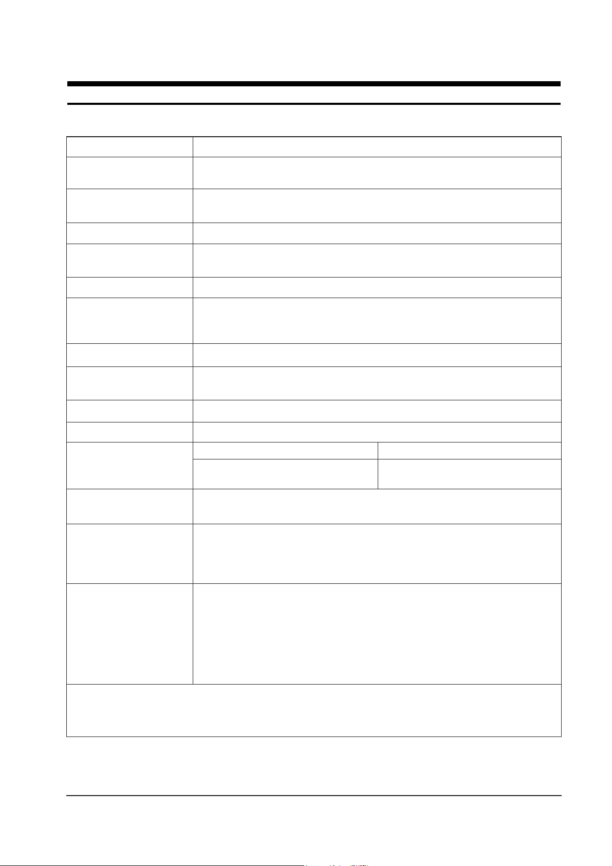
3-1 Specifications
LCD Panel TFT-LCD panel, RGB vertical stripe, normaly white, 15-Inch viewable,
0.297 (H) x 0.297 (V) pixel pitch, 13.3-Inch viewable, 0.264 (H) x 0.264 (V) pixel pitch
Scanning Frequency Horizontal : 30 kHz to 61 kHz (Automatic)
Vertical : 50 Hz to 75 Hz (Automatic)
Display Colors 16.7 Million colors
Maximum Resolution Horizontal : 1024 Pixels
Vertical : 768 Pixels
Input Video Signal Analog, 0.714 Vp-p ± 5% positive at 75 Ω, internally terminated
Input Sync Signal Type: Seperate H/V sync, Composite H/V, Sync-on-Green, automatic synchronization
without external switch of sync type
Level: TTL level
Maximum Pixel Clock rate 80 MHz
Active Display 13.3”: 270.3 mm / 207.8 mm
Horizontal/Vertical 15”: 304.1 mm / 228.1 mm
AC power voltage & Frequency AC 90 to 264 Volts, 60/ 50 Hz ± 3 Hz
Power Consumption 13.3”: 40 W (max.), 15”: 45 W (max.)
Dimensions 13.3” 15”
Unit (W x D x H) 13.9x7.7x15.6 Inches (354.3 x 195.6 x 395 mm) 15.9x7.7x16.5 Inches (404 x 196.6 x 418.7 mm)
Carton (W x D x H) 17.9 x 11.1 x 19.2 Inches (455 x 282 x 488 mm) 18.7 x 11.1 x 20.1 Inches (475 x 282 x 510 mm)
Weight
(Net/Gross) 13.3”: 6.4 kg / 8.0 kg, 15”: 7.5 kg / 9.5 kg
Environmental Considerations Operating Temperature : 50°F to 104°F (10°C to 40°C)
Humidity : 10 % to 80 %
Storage Temperature : -13°F to 113°F (-25°C to 45°C)
Humidity : 5 % to 95 %
Audio Characteristics • Audio Characteristics
• Built-in Microphone: High-sensitivity condenser microphone (mono)
• Audio input: Left/Right Stereo phone jack, 0.7 Vrms
• Sound output: 1 W (left) + 1 W (right)/THD 1% at 8ohm
• Frequency response: 80 Hz~20 kHz (at –3dB)
• Headphone: Max 50mW output (3.5-pi jack)
• Speaker: Internal semi Dome (8ohm x 2)
• SyncMaster 320TFT/520TFT complies with SWEDAC (MPR II) recommendations for reduced electromagnetic fields.
• Designs and specifications are subject to change without prior notice.
SyncMaster 320TFT/520TFT 3-1
Item Description
16 ~26 GND GND GND
3 Product Specifications
3-2 SyncMaster 320TFT/520TFT
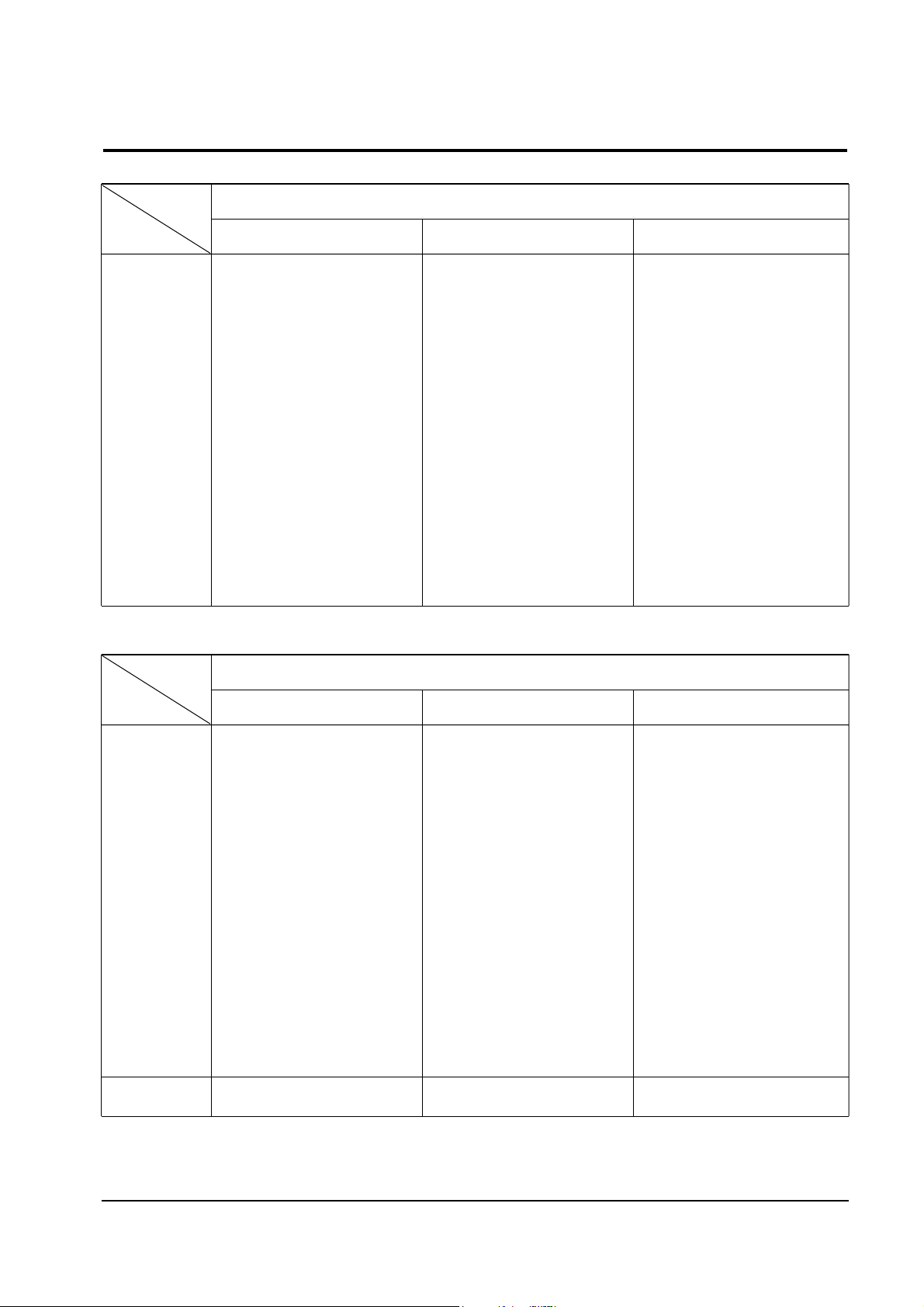
3-2 Pin Assignments
Sync
Type
Pin No.
15-Pin Signal Cable Connector
Separate Composite Sync-on-green
Sync-on-green
1
2
3
4
5
6
7
8
9
10
11
12
13
14
15
Red
Green
Blue
GND
GND (DDC Return)
GND-R
GND-G
GND-B
No Connection
GND-Sync/Self Test
GND
DDC Data
H-Sync
V-Sync
DDC Clock
Red
Green
Blue
GND
GND (DDC Return)
GND-R
GND-G
GND-B
No Connection
GND-Sync/Self Test
GND
DDC Data
H/V-Sync
Not Used
DDC Clock
Red
Green + H/V Sync
Blue
GND
GND (DDC Return)
GND-R
GND-G
GND-B
Not Used
GND-Sync/Self Test
GND
DDC Data
Not Used
Not Used
DDC Clock
Sync
Type
Pin No.
26-Pin Signal Cable Connector
Separate Composite
1
2
3
4
5
6
7
8
9
10
11
12
13
14
15
Red
Green
Blue
GND
GND (DDC Return)
GND-R
GND-G
GND-B
No Connection
GND-Sync/Self Test
GND
DDC Data
H-Sync
V-Sync
DDC Clock
Red
Green
Blue
GND
GND (DDC Return)
GND-R
GND-G
GND-B
No Connection
GND-Sync/Self Test
GND
DDC Data
H/V-Sync
Not Used
DDC Clock
Red
Green + H/V Sync
Blue
GND
GND (DDC Return)
GND-R
GND-G
GND-B
Not Used
GND-Sync/Self Test
GND
DDC Data
Not Used
Not Used
DDC Clock
31.469
31.778
3.813
1.589
26.058
0.318
70.086
14.268
0.064
1.716
11.504
0.985
25.175
Positive
Negative
Separate
fH (kHz)
A µsec
B µsec
C µsec
D µsec
E µsec
fV (Hz)
O msec
P msec
Q msec
R msec
S msec
Clock
Frequency
(MHz)
Polarity
H.Sync
V.Sync
Remark
IBM
3 Product Specifications
SyncMaster 320TFT/520TFT 3-3
QRS
P
O
Video
Sync
Sync
Horizontal
Vertical
CDE
P
O
B
A
Video
Sync
Sync
Separate Sync
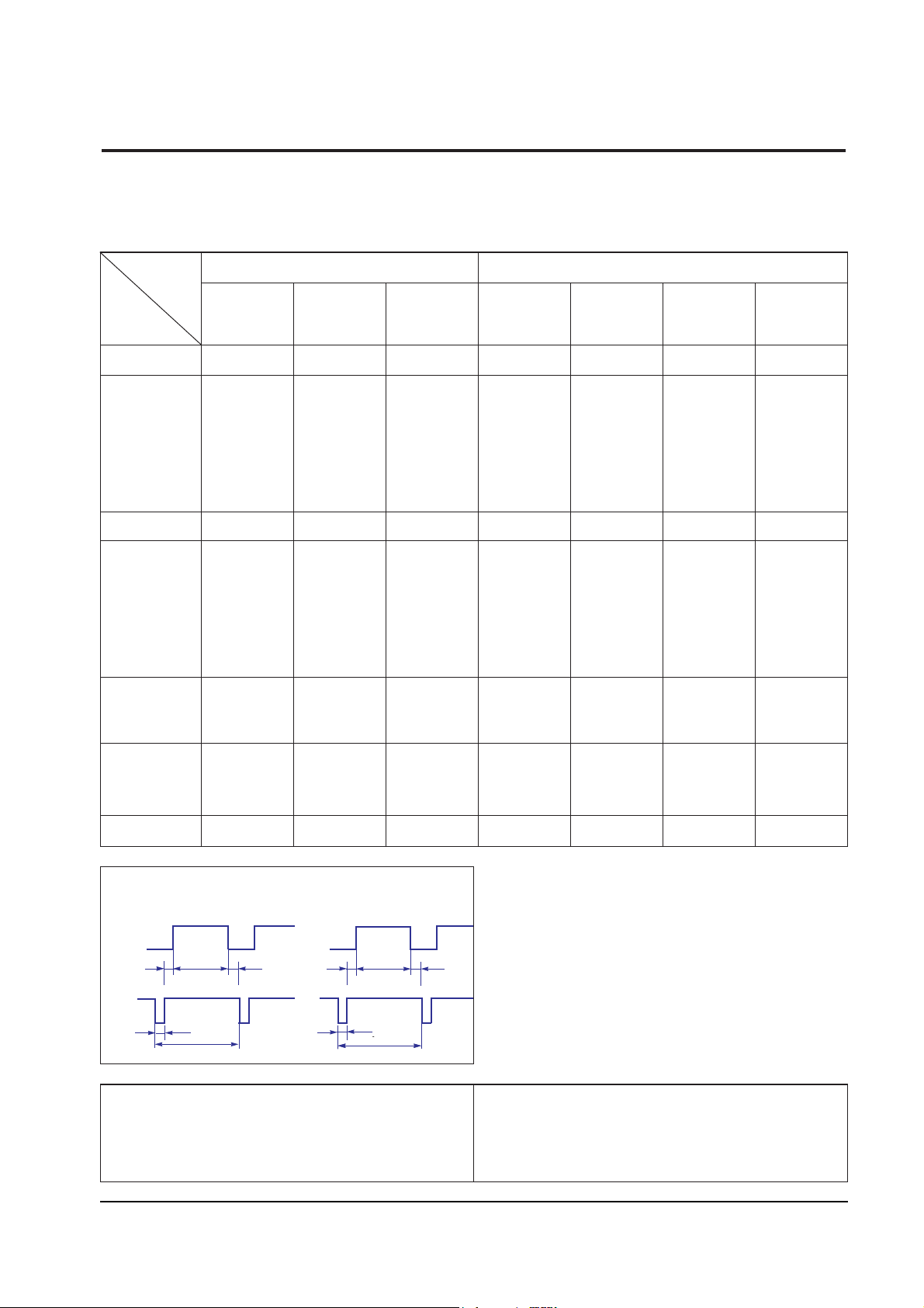
3-3 Timing Chart
This section of the service manual describes the timing that the computer industry recognizes as standard
for computer-generated video signals.
C D
A
O
E
B
P
Video
Sync
Sync
Video
Q R S
A : Line time total B : Horizontal sync width O : Frame time total P : Vertical sync width
C : Back porch D : Active time Q : Back porch R : Active time
E : Front porch S : Front porch
VGA3/60 Hz
640 x 480
640/72 Hz
640 x 480
640/75 Hz
640 x 480
800/56 Hz
800 x 600
800/60 Hz
800 x 600
VGA1/70 Hz
640 x 350
VGA2/70 Hz
720 x 400
Table 3-1. Timing Chart
31.469
31.777
3.813
1.589
26.058
0.318
70.087
14.268
0.064
0.858
13.155
0.191
28.322
Negative
Positive
Separate
31.469
31.778
3.813
1.589
26.058
0.318
59.940
16.683
0.064
0.794
15.761
0.064
25.175
Negative
Negative
Separate
37.861
26.413
1.270
3.810
20.825
0.508
72.809
13.735
0.079
0.528
13.100
0.026
31.500
Negative
Negative
Separate
37.500
26.667
2.032
3.810
20.317
0.508
75.000
13.333
0.080
0.427
12.800
0.027
31.500
Negative
Negative
Separate
35.156
28.444
2.000
3.556
22.222
0.667
56.250
17.778
0.057
0.626
17.067
0.028
36.000
Positive
Negative
Separate
37.879
26.400
3.200
2.200
20.000
1.000
60.317
16.579
0.106
0.607
15.840
0.026
40.000
Positive
Positive
Separate
Mode
VESA
Timing
3 Product Specifications
3-4 SyncMaster 320TFT/520TFT
48.077
20.800
2.400
1.280
16.000
1.120
72.188
13.853
0.125
0.478
12.480
0.770
50.000
Positive
Positive
Separate
fH (kHz)
A µsec
B µsec
C µsec
D µsec
E µsec
fV (Hz)
O msec
P msec
Q msec
R msec
S msec
Clock
Frequency
(MHz)
Polarity
H.Sync
V.Sync
Remark
VESA
1024/60 Hz
1024 x 768
1024/70 Hz
1024 x 768
1024/75 Hz
1024 x 768
640/67 Hz
60 x 480
832/75 Hz
832 x 624
800/72 Hz
800 x 600
800/75 Hz
800 x 600
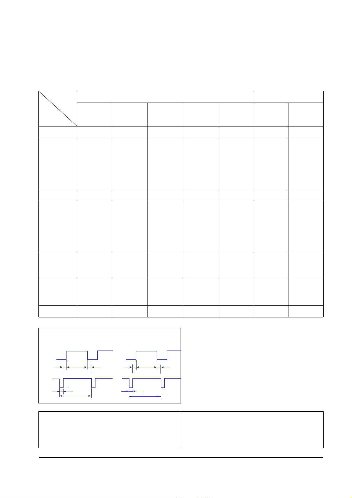
Table 3-1. Timing Chart Continued
46.875
21.333
1.616
3.232
16.162
0.323
75.000
13.333
0.064
0.448
12.800
0.021
49.500
Positive
Positive
Separate
48.363
20.677
2.092
2.462
15.754
0.369
60.004
16.666
0.124
0.600
15.880
0.062
65.000
Negative
Negative
Separate
56.476
17.707
1.813
1.920
13.653
0.320
70.069
14.272
0.106
0.513
13.599
0.053
75.000
Negative
Negative
Separate
60.023
16.660
1.219
2.235
13.003
0.203
75.029
13.328
0.050
0.466
12.795
0.017
78.750
Positive
Positive
Separate
35.000
28.571
2.116
3.175
21.164
2.116
66.667
15.000
0.086
1.114
13.714
0.086
30.240
Negative
Negative
Separate
49.726
20.110
1.117
3.910
14.524
0.559
74.551
13.414
0.060
0.784
12.549
0.020
57.284
Negative
Negative
Separate
Mode
MAC.
Timing
QRS
P
O
Video
Sync
Sync
Horizontal
Vertical
CDE
P
O
B
A
Video
Sync
Sync
Separate Sync
C D
A
O
E
B
P
Video
Sync
Sync
Video
Q R S
A : Line time total B : Horizontal sync width O : Frame time total P : Vertical sync width
C : Back porch D : Active time Q : Back porch R : Active time
E : Front porch S : Front porch
MENU
EXIT
ON/OFF
VOLUME
MIN MAX
BASS
MIN MAX
TREBLE
MIN MAX
MIC
ON OFF
SyncMaster 320TFT/520TFT 4-1
4 Opearating Instructions
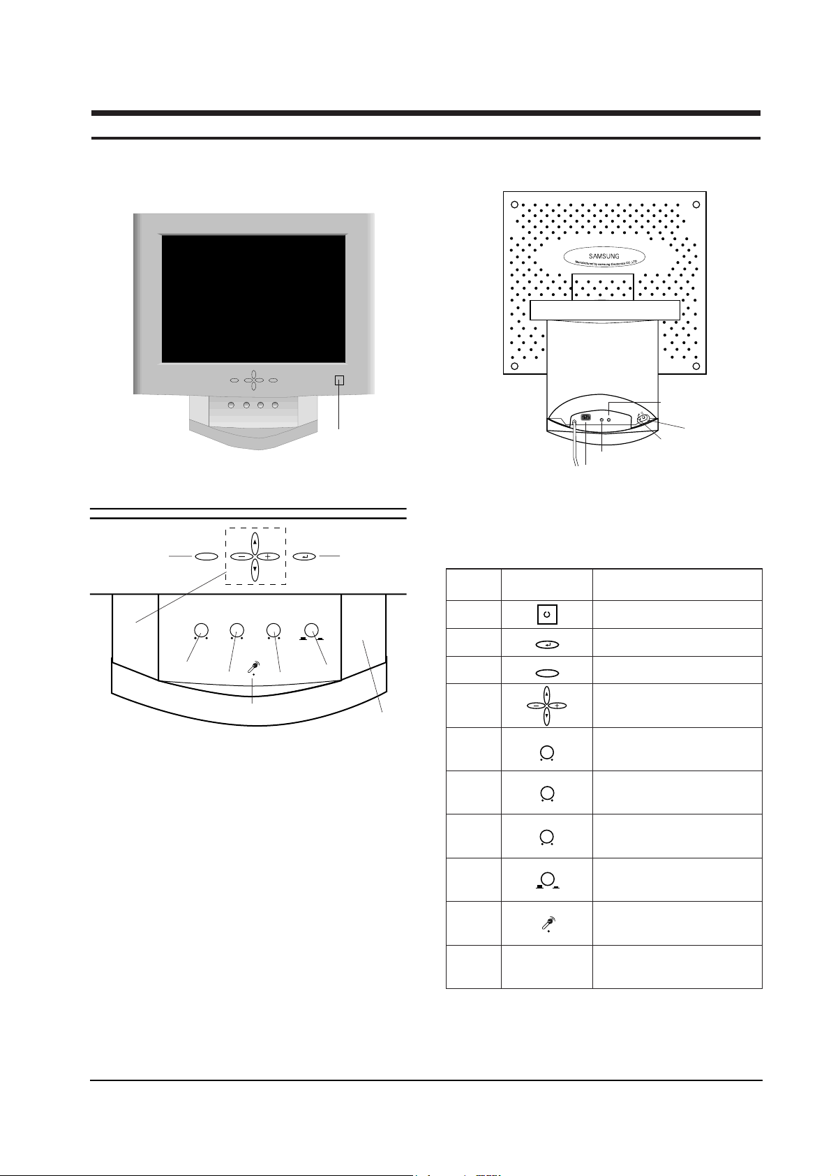
4-1 Control and Connectors
EXIT
MENU
ON/OFF
VOLUME BASS
TREBLE
MIC
MIN MAX MIN MAX MIN MAX
ON OFF
MIC
AUDIO
OUT IN
Figure 4-2. Rear View
Figure 4-1. Front View and Control
1
2
3
4
5
67
8
9
10
1 Power Button
Menu Button
Exit Button
Up / Down / + / – Buttons
Audio On / Off & Volume Buttons
Bass Button
Treble Button
Microphone On / Off Button
Microphone
Amplified Stereo Speakers
3
4
5
6
7
8
9
10
2
Location Symbol Description
Table 4-1. Front Panel Controls
Power port
Microphone out port
Audio in port
Headphone jack
External microphone jack
This monitor has no Òservice onlyÓ micom
controls. Should there be a problem with the
microprocessor, replace the entire circuit board.
There are, however, user accessible adjustment
features that are described below.
This monitor has factory preset display settings
for each of the signals listed in the standard
display modes Timing Chart (see pages 3-3 and
3-4). As a result, when the monitor senses one of
the standard signal timings, it automatically
adjusts to an optimum size and position.
However, the user may wish to adjust the monitor
to their own preferred settings rather than use
those preset at the factory. The monitor saves up
to 16 user defined settings.
4-2-1 OSD Window
The adjustable features described below all use
the on-screen menu system.
1. Push the ↵ button to open the display the on-
screen menu.
2. Use the or button to change an
adjustment icon, use the ↵ button to highlight
an adjustment icon, then use the + or Ð
buttons to make the adjustments.
3. To select another adjustment on the same
screen, use the or button to move to the
next selection.
4. When you are done making adjustments on an
adjustment icon, push the EXIT button.
5. When you are done making all adjustments,
push the EXIT button.
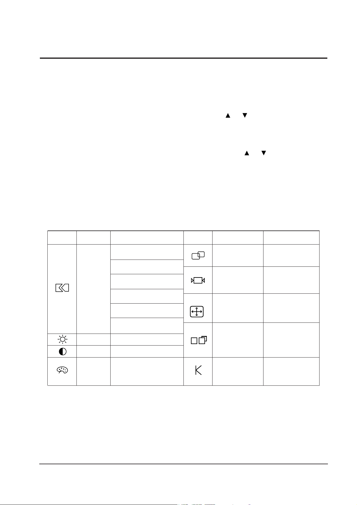
Table 4-2 shows the adjustment types and their
icons.
4 Operating Instructions
4-2 SyncMaster 320TFT/520TFT
4-2 Microprocessor Controls and Functions
Brightness
Contrast
Auto Reset
Auto Adjustment
Geometry
Color
Misc.
Language
Menu Position
Menu Display Time
Display Mode
0 ~ 100
0 ~ 100
No/Yes
No/Yes
No/Yes
x1, x2, x4, x8
Normal/Expand
Color Temperature
Mode1
Mode2
Mode3
0 ~ 100
0 ~ 100
0 ~ 100
Color Control
Red
Green
Blue
Image Size
Zoom
Display Size
0 ~ 100
0 ~ 100
0 ~ 100
0 ~ 100
Image Lock
Fine
Coarse
Position
Horizontal
Vertical
IBM VGA1/70 Hz 0-100
740-860
VGA2/70 Hz 0-100
840-960
VGA3/60 Hz 0-100
740-860
VESA SVGA/56 Hz 0-100
964-1084
SVGA/60 Hz 0-100
996-1116
XGA/60 Hz 0-100
1284-1404
Icon Description Adjustment Range Icon Description Adjustment Range
Table 4-2. Available adjustments
4 Operating Instructions
SyncMaster 320TFT/520TFT 4-3
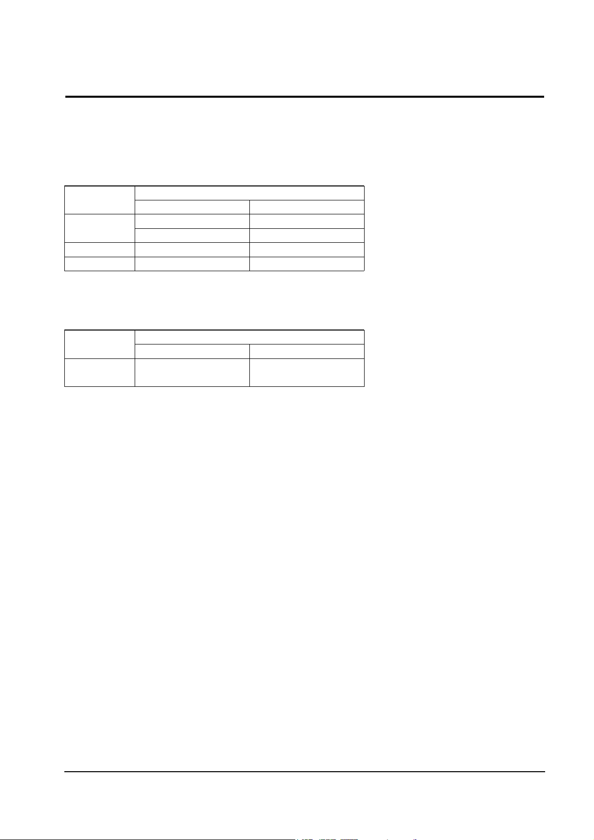
4-3 Audio Controls
Your LCD monitor provides four audio control buttons located on the front of the stand.
4-3-1 Audio Adjustments
To access the on/off, volume, bass and treble functions push the appropriate blue control button until it
pops out then turn it to the right or left to adjust the function.
Function
Name
Audio On/Off
and Volume
Effect of Control Movement
Left Right
Off
Decrease volume
Decrease Low sounds
Decrease high sounds
Bass
Treble
On
Increase volume
Increase low sounds
Increase High sounds
Function
Name
Audio On/Off
and Volume
Effect of Control Movement
In Out
Off On
Your LCD monitor includes an internal microphone which you can turn On or Off using the rightmost
control of the Audio controls.
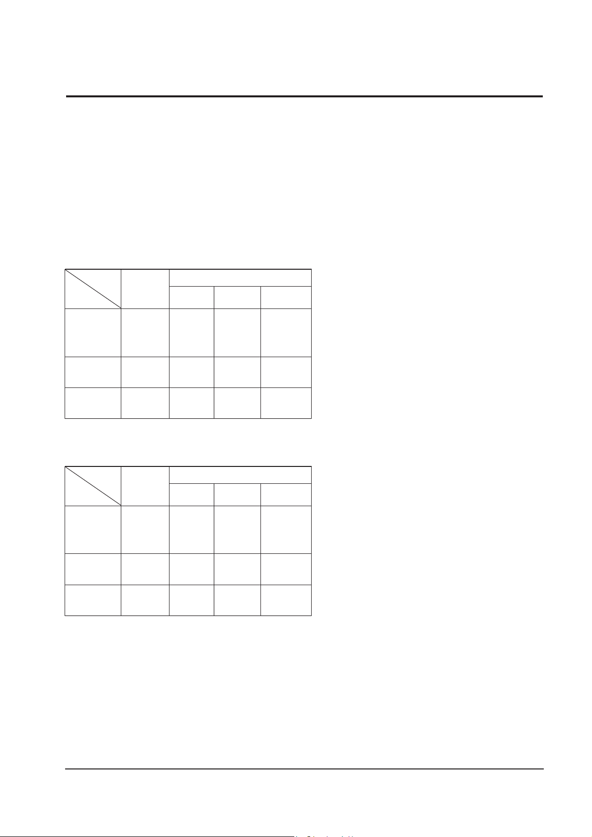
This monitor has a built-in power management
system called PowerSaver. This system saves
energy by switching your monitor into an off
mode when it has not been used for an certain
amount of time.
This system operates with a VESA DPMS
compliant video card installed in your computer.
You use a software utility installed on your
computer to set up this feature. See the table
below for details.
Note 1: This monitor automatically returns to
normal operation when horizontal and
vertical sync return. This occurs when you
move the computer's mouse or press a key
on the keyboard.
Note 2: This monitor is EPA ENERGY STAR
¨
compliant and NUTEK compliant when
used with a computer equipped with
VESA DPMS functionality. If your
computer system cannot support a display
power management function, you can
purchase an optional DPMS software
program to enable the power saving
function. Please contact Samsung or your
dealer for more information.
Note 3: For energy conservation, turn your
monitor OFF when it is not needed, or
when leaving it unattended for long
periods.
Note 4: Audio Part is operated separately by
control button.
4 Operating Instructions
4-4 SyncMaster 320TFT/520TFT
4-4 Power Management System
Table 4-3. Display Power Management Signaling (DPMS); 13.3”
State
Items
Normal
Operation
Horizontal Sync
Vertical Sync
Video
Power
Indicator
Power
Consumption/hr
Active
Active
Active
Green Amber
Amber
Blinking
(0.5 sec)
Amber
Blinking
(1 sec)
40 W (max.)
30 W
(nominal)
Less than
5 W
Less than
5 W
Less than
5 W
Inactive
Active
Blanked
Active
Inactive
Blanked
Power saving function EPA/NUTEK
Stand-By
Mode
Suspend Mode
Position A
Power Off Mode
Position B
Inactive
Inactive
Blanked
Table 4-4. Display Power Management Signaling (DPMS); 15”
State
Items
Normal
Operation
Horizontal Sync
Vertical Sync
Video
Power
Indicator
Power
Consumption/hr
Active
Active
Active
Green Amber
Amber
Blinking
(0.5 sec)
Amber
Blinking
(1 sec)
45 W (max.)
35 W
(nominal)
Less than
5 W
Less than
5 W
Less than
5 W
Inactive
Active
Blanked
Active
Inactive
Blanked
Power saving function EPA/NUTEK
Stand-By
Mode
Suspend Mode
Position A
Power Off Mode
Position B
Inactive
Inactive
Blanked
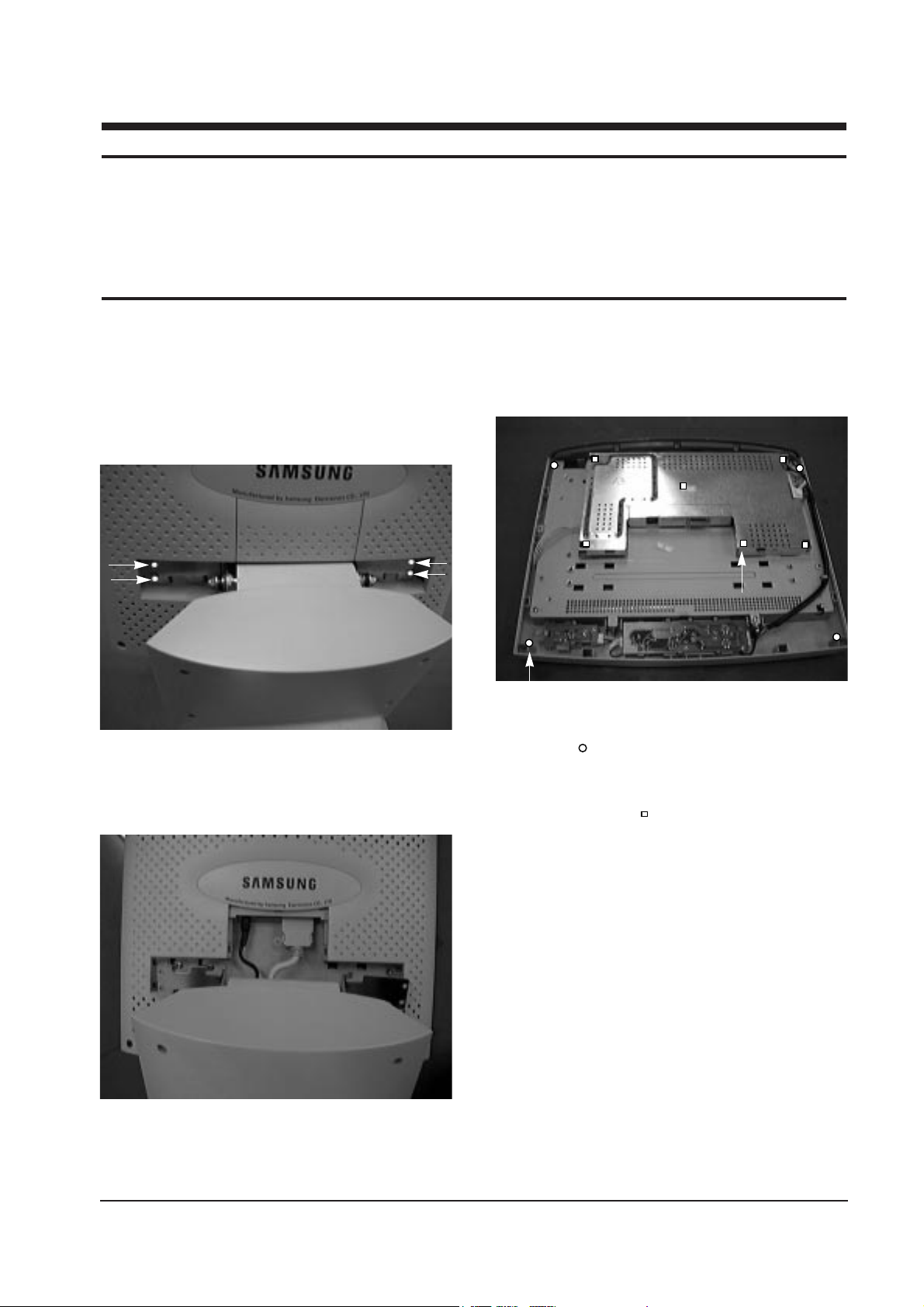
5-1-1 Removing the Stand
1. Remove 2 hinge caps on the Rear Cover.
2. Remove 4 screws in the hinge area.
3. Push the Stand to the left and remove the
Stand from Body (Front).
4. Remove the Cover Signal.
5. Disconnect Power Cord and Signal Cable.
5-1-2 Front Cover Disassembly
1. Remove the 4 screws on Rear Cover.
(Point ; )
2. Remove Rear Cover from Front Cover.
3. Remove 6 Main PCB screws on Rear Panel
Bracket. (Point ; )
4. Disconnect Main PCB, Inverter wire, Function
wire and Interface wire.
5. Remove Main PCB Assembly.
SyncMaster 320TFT/520TFT 5-1
5 Disassembly and Reassembly
This section of the service manual describes the disassembly and reassembly procedures for the
SyncMaster 320TFT/520TFT monitors.
WARNING: This monitor contains electrostatically sensitive devices. Use caution when handling
these components.
5-1 Disassembly
Cautions:1. Disconnect the monitor from the power source before disassembly.
2. Follow these directions carefully; never use metal instruments to pry apart the cabinet.
Figure 5-1
Figure 5-3
Figure 5-2
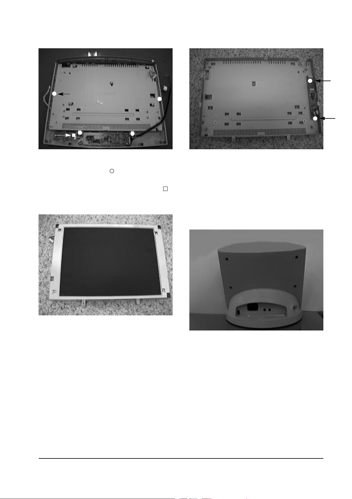
6. Remove 4 screws on the Rear Panel Bracket.
(15Ó : 6 screws)- Point;
7. Remove Bracket Panel from Front Cover.
8. Remove 1 screw on the Power PCB. (Point; )
9. Remove Function PCB from locking area of
Function Knob.
10. Remove 4 screws on the Front Bracket Panel.
11. Remove Front Bracket Panel.
12. Disconnect jack between Panel and Inverter
PCB.
13. Remove Rear Bracket Panel.
14. Remove 2 connecting screws between Rear
Bracket and Inverter PCB.
15. Remove Interface wire on the Rear side of
Panel.
5-1-3 Stand Disassembly
1. Stand the stand assembly with the base close
to you.
2. Remove the 4 screws on the back cover of the
stand and remove it.
3. Stand the stand assembly upside down.
5 Disassembly and Reassembly
5-2 SyncMaster 320TFT/520TFT
Figure 5-4
Figure 5-5
Figure 5-6
Figure 5-7
 Loading...