

Page 1
IMPORTADO POR
SAMSUNG ELECTRONICS MEXICO. S.A. DE C.V.
Via Lopez Portillo No. 6, Col. San Francisco
Chilpan Tultitlan, Estado de Mexico C.P. 54940, Mexico
D.F. Mexico
Tel) 01(55) 5317-2551/3410/3409
Fax) 01(55) 5317-3377
Owner’s Instructions LCD TV with Life-Like Picture & Sleek Design LTN325W I LTN406W
EXPORTADO POR
Samsung Electronics Co., Ltd.
416, Maetan-3dong, Yeongtong-Gu,
Suwon City, Kyungki-Do Korea
This device is a Class B digital apparatus.
BN68-00448R-05
Page 2
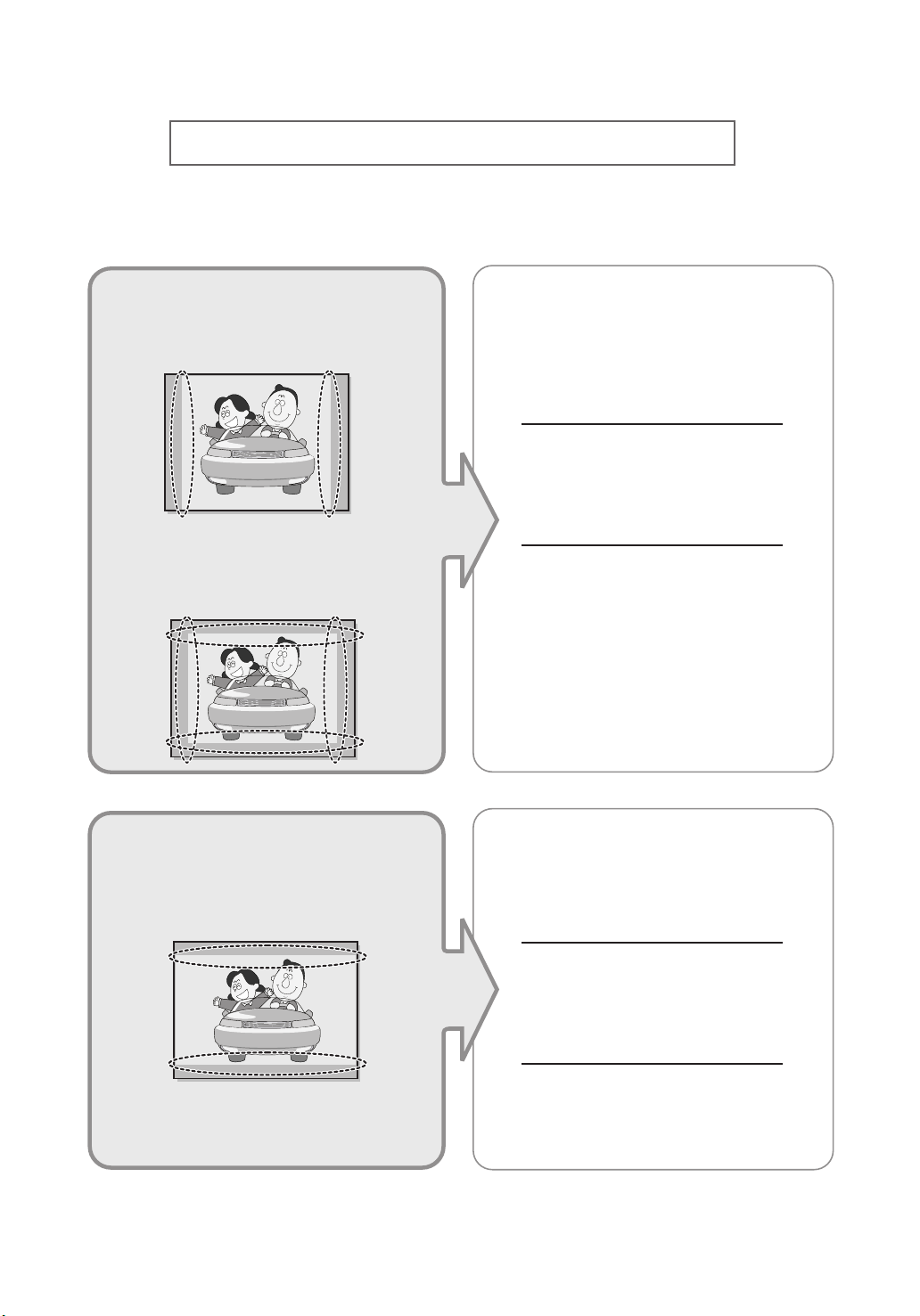
Precautions When Displaying a Still Image
A still image may cause permanent damage to the TV screen.
•
Digital Ready TV: When you
select the regular screen (4:3)
mode to watch an SD-grade
digital broadcast (and the set-top
box output is 480p).
•
Digital Ready TV: When you
select the wide screen (16:9)
mode to watch an SD-grade
digital broadcast (and the set-top
box output is 1080i).
Although digital broadcasting must be in the
wide screen (16:9) HD format, broadcasters
sometimes show programs made originally
in the regular screen format (4:3) by
converting the signals into digital form, in
which case the left and right side edges of
the screen are cropped.
Note : If the borders at the left, right and the
center of the screen remain fixed for
an extended period of time, the
amount of light transmission will also
remain varied and as a result the
borders may leave traces.
Do not leave the screen in pause mode for
extended periods of time as you may
experience temporary or permanent image
burn.
•
Digital Ready TV: When the
TV receives HD-grade signals
(and the set-top box output is 1080i).
When you watch a digital HD-grade broadcast
on a regular (4:3) TV with the screen size
"16:9" or "Panorama" selected, you will be
able to watch the program but the top and
bottom edges of the screen will be cropped.
Note : If the borders at the top, bottom and
the center of the screen remain fixed
for an extended period of time, the
amount of light transmission will also
remain varied and as a result the
borders may leave traces.
Do not leave the screen in pause mode for
extended periods of time as you may
experience temporary or permanent image
burn.
Page 3
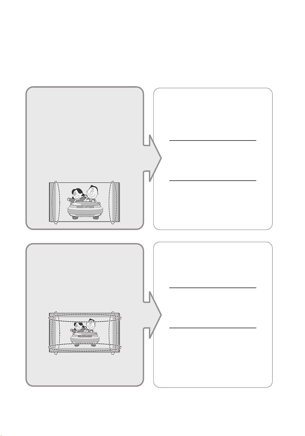
• Integrated
(Wide-screen): When the TV
receives SD-grade (regular)
broadcasting signals (receives
480p regular signals).
•
Digital Ready TV
digital TV: When the TV receives
SD-grade (regular) broadcasting
signals (with a set-top box).
Digital TV
(wide-screen):
• When you watch an analog
(regular) broadcast on a
wide-screen TV (with the 4:3 screen
mode selected).
Although digital broadcasting must be in the
wide screen (16:9) HD format, broadcasters
sometimes show programs made originally
in the regular screen format (4:3) by
converting the signals into digital form, in
which case the left and right side edges of
the screen are cropped.
Note : If the borders at the left, right and the
center of the screen remain fixed for
an extended period of time, the
amount of light transmission will also
remain varied and as a result the
borders may leave traces.
Do not leave the screen in pause mode for
extended periods of time as you may
experience temporary or permanent image
burn.
•
When you watch a DVD, CD or a
video in wide screen (21:9) format on
a wide-screen (16:9) TV.
• When you connect a computer or a
game console to the TV and select
the 4:3 screen mode.
If you connect a DVD player, computer or a
game console to the wide-screen TV and
watch a movie or play a game in regular
(4:3) or wide (21:9) screen mode, the left
and right side edges, or the top and bottom
edges of the screen will be cropped.
Note : If the borders at the left, right and the
center of the screen remain fixed for
an extended period of time, the
amount of light transmission will also
remain varied and as a result the
borders may leave traces.
Do not leave the screen in pause mode for
extended periods of time as you may
experience temporary or permanent image
burn.
Page 4

Important
Safety Instructions
1) Read these instructions.
2) Keep these instructions.
3) Heed all warnings.
4) Follow all instructions.
5) Do not use this apparatus near water.
6) Clean only with dry cloth.
7) Do not block any ventilation openings, Install in accordance with the manufacturer’s
instructions.
8) Do not install near any heat sources such as radiators, heat registers, or other apparatus
(including amplifiers) that produce heat.
9) Do not defeat the safety purpose of the polarized or grounding-type plug. Apolarized plug
has two blades with one wider than the other. A grounding type plug has two blades and a
third grounding prong. The wide blade or the third prong are provided for your safety.
If the provided plug does not fit into your outlet, consult an electrician for replacement
of the obsolete outlet.
10) Protect the power cord from being walked on or pinched particu
larly at plugs, convenience receptacles, and the point where they
exit from the apparatus.
11) Only use attachments/accessories specified by the manufacturer.
12) Use only with cart, stand, tripod, bracket, or table specified by
the manufacturer, or sold with the apparatus. When a cart is used,
use caution when moving the cart/apparatus combination to avoid
injury from tip-over.
13) Unplug this apparatus during lightning storms or when unused
for long periods of time.
14) Refer all servicing to qualified service personnel. Servicing is required when the apparatus
has been damaged in any way, such as power-supply cord or plug is damaged, liquid has
been spilled or objects have fallen into the apparatus, the apparatus has been exposed to
rain or moisture, does not operate normally, or has been dropped.
SAFETY 1
Page 5
CAUTION
RISK OF ELECTRIC SHOCK DO NOT OPEN
CAUTION: TO REDUCE THE RISK OF ELEC
TRIC SHOCK, DO NOT REMOVE COVER
(OR BACK). NO USER SERVICEABLE PARTS
INSIDE. REFER SERVICING TO QUALIFIED
SERVICE PERSONNEL.
This symbol indicates high voltage is
present inside. It is dangerous to make
any kind of contact with any inside part
of this product.
This symbol alerts you that important
literature concerning operation and
maintenance has been included with this
product.
Note to CATV system installer: This reminder is provided to call CATV system
installer’s attention to Article 820-40 of the National Electrical Code (Section 54 of
Canadian Electrical Code, Part I), that provides guidelines for proper grounding and,
in particular, specifies that the cable ground shall be connected to the grounding
system of the building as close to the point of cable entry as practical.
Caution: FCC/CSA regulations state that any unauthorized changes or modifications
to this equipment may void the user’s authority to operate it.
Caution: To prevent electric shock, match the wide blade of plug to the wide slot, and
fully insert the plug.
Attention: pour eviter les chocs electriques, introduire la lame le plus large de la
fiche dans la borne correspondante de la prise et pousser jusqu’au fond.
Important: One Federal Court has held that unauthorized recording of
copyrighted TV programs is an infringement of U.S. copyright laws.
Certain Canadian programs may also be copyrighted and any unauthorized recording
in whole or in part may be in violation of these rights.
WARNING: To prevent damage which may result in fire or
electric shock hazard, do not expose this appliance
to rain or moisture.
As an ENERGY STAR Partner.
Samsung Electronics America, Inc. has determined that this product or product
model meets the ENERGY STAR guidelines for energy efficiency.
SAFETY 2
Page 6

FCC Information
User Instructions
The Federal Communications Commission Radio
Frequency Interference Statement includes the
following warning:
NOTE: This equipment has been tested and found
to comply with the limits for a Class B digital
device, pursuant to Part 15 of the FCC Rules.
These limits are designed to provide reasonable
protection against harmful interference in a residential installation. This equipment generates,
uses, and can radiate radio frequency energy and,
if not installed and used in accordance with the
instructions, may cause harmful interference to
radio communications. However, there is no guarantee that interference will not occur in a particular
installation.
If this equipment does cause harmful interference
to radio or television receptions, which can be
determined by turning the equipment off and on,
the user is encouraged to try to correct the interference by one or more of the following measures:
• Reorient or relocate the receiving antenna.
• Increase the separation between the
equipment and receiver.
• Connect the equipment into an outlet on a
circuit different from that to which the
receiver is connected.
• Consult the dealer or an experienced
radio/TV technician for help.
User Information
Changes or modifications not expressly approved
by the party responsible for compliance could
void the user’s authority to operate the equipment.
If necessary, consult your dealer or an experienced radio/television technician for additional
suggestions. You may find the booklet called How
to Identify and Resolve Radio/TV Interference
Problems helpful. This booklet was prepared by
the Federal Communications Commission. It is
available from the U.S. Government Printing
Office, Washington, DC 20402, Stock Number
004-000-00345-4.
The party responsible for product compliance:
SAMSUNG ELECTRONICS CO., LTD
America QA Lab of Samsung
3351 Michelson Drive,
Suite #290, Irvine, CA92612 USA
Warning
User must use shielded signal interface cables to
maintain FCC compliance for the product.
Provided with this monitor is a detachable power
supply cord with IEC320 style terminations.
It may be suitable for connection to any UL Listed
personal computer with similar configuration.
Before making the connection, make sure the voltage rating of the computer convenience outlet is
the same as the monitor and that the ampere rating of the computer convenience outlet is equal to
or exceeds the monitor voltage rating.
For 120 Volt applications, use only UL Listed
detachable power cord with NEMA configuration
5-15P type (parallel blades) plug cap. For 240 Volt
applications use only UL Listed Detachable power
supply cord with NEMA configuration 6015P type
(tandem blades) plug cap.
IC Compliance Notice
This Class B digital apparatus meets all requirements of the Canadian nterference-Causing
Equipment Regulations of ICES-003.
Cet appareil Numérique de classe B respecte
toutes les exigences du Règlemont NMB-03 sur
les équipements produisant des interférences au
Canada.
Notice de Conformité IC
Cet appareil numérique de classe B respecte
toutes les exigences du Règlement ICES-003 sur
les équipements produisant des interférences au
Canada.
VCCI
This is a Class B product based on the standard
of the Voluntary Control Council for Interference
by Information Technology Equipment (VCCI). If
this is used near a radio or television receiver in a
domestic environment, it may cause radio interference. Install and use the equipment according to
the instruction manual.
This Class B digital apparatus complies with
Canadian ICES-003. Cet appareil numéique de la
classe B estconforme à la norme NMB-003 du
Canada.
This device complies with part 15 of the FCC Rules. Operation is subject to the following two conditions:
(1) This device may not cause harmful interference, and
(2) This device must accept any interference received, including interference that may cause unesired operation.
This television receiver provides display of television closed captioning in accordance with §15.119 of the FCC rules.
SAFETY 3
Page 7

Important Warranty Information
Regarding Television Format
Viewing
Standard screen format televisions (4:3, the aspect ratio of the screen width to height) are primarily
designed to view standard format full-motion video. The images displayed on them should primarily
be in the standard 4:3 ratio format and constantly moving.
Displaying stationary graphics and images on screen, such as the dark top and bottom letterbox bars
(wide screen pictures), should be limited to no more than 15% of the total television viewing per week.
Wide screen format televisions (16:9, the aspect ratio of the screen width to height) are primarily
designed to view wide screen format full-motion video. The images displayed on them should primarily
be in the wide screen 16:9 ratio format, or expanded to fill the screen if your model offers this feature,
and constantly moving. Displaying stationary graphics and images on screen, such as the dark
side-bars on non-expanded standard format television video and programming, should be limited to
no more than 15% of the total television viewing per week.
Additionally, viewing other stationary images and text such as stock market reports, video game
displays, station logos, web sites or computer graphics and patterns, should be limited as described
above for all televisions. Displaying any stationary images that exceed the above guidelines can
cause uneven aging of picture tubes (LCDs) that leave subtle, but permanent burned-in ghost images
in the television picture. To avoid this, vary the programming and images, and primarily display full
screen moving images, not stationary patterns or dark bars. On television models that offer picture
sizing features, use these controls to view the different formats as a full screen picture.
Be careful in the selection and duration of television formats used for viewing. Uneven LCD aging
as a result of format selection and use, as well as other burned-in images, is not covered by your
Samsung limited warranty.
[Note]
If a still image is displayed for an extended period of time, residual images or blurring may appear.
When you need to leave the monitor unused for an extended period of time, adjust the settings so
that the monitor automatically goes into energy saving mode or activates the screen saver to display
moving images.
SAFETY 4
Page 8

MEMO
Page 9

CONTENTS
Chapter 1: Your New TV . . . . . . . . . . . . . . . . 1
List of Features . . . . . . . . . . . . . . . . . . . . . . . . . . . . . . . . . . . . . . . . . . . .1
List of Parts . . . . . . . . . . . . . . . . . . . . . . . . . . . . . . . . . . . . . . . . . . . . . . .1
Familiarizing Yourself with Your New TV . . . . . . . . . . . . . . . . . . . . . . .2
Front Panel Buttons . . . . . . . . . . . . . . . . . . . . . . . . . . . . . . . . .2
Rear Panel Jacks . . . . . . . . . . . . . . . . . . . . . . . . . . . . . . . . . . . .3
Remote Control . . . . . . . . . . . . . . . . . . . . . . . . . . . . . . . . . . . . .4
Installing Batteries in the Remote Control . . . . . . . . . . . . . . . .6
Chapter 2: Installation . . . . . . . . . . . . . . . . . . 7
Connecting VHF and UHF Antennas . . . . . . . . . . . . . . . . . . . . . . . . . . .7
Antennas with 300-ohm Flat Twin Leads . . . . . . . . . . . . . . . . .7
Antennas with 75-ohm Round Leads . . . . . . . . . . . . . . . . . . . .8
Separate VHF and UHF Antennas . . . . . . . . . . . . . . . . . . . . . .8
Connecting Cable TV . . . . . . . . . . . . . . . . . . . . . . . . . . . . . . . . . . . . . . .8
Cable without a Cable Box . . . . . . . . . . . . . . . . . . . . . . . . . . . .8
Connecting to a Cable Box that Descrambles All Channels . . .9
Connecting to a Cable Box that
Descrambles Some Channels . . . . . . . . . . . . . . . . . . . . . . . . . .9
Connecting a VCR . . . . . . . . . . . . . . . . . . . . . . . . . . . . . . . . . . . . . . . . .11
Connecting an S-VHS VCR . . . . . . . . . . . . . . . . . . . . . . . . . .12
Connecting a DVD Player . . . . . . . . . . . . . . . . . . . . . . . . . . . . . . . . . . .13
Connecting a Digital TV Set-Top Box . . . . . . . . . . . . . . . . . . . . . . . . .13
Connecting the Speakers . . . . . . . . . . . . . . . . . . . . . . . . . . . . . . . . . . . .14
Connecting a PC . . . . . . . . . . . . . . . . . . . . . . . . . . . . . . . . . . . . . . . . . .15
Chapter 3: Special Features . . . . . . . . . . . .16
Turning the TVOn and Off . . . . . . . . . . . . . . . . . . . . . . . . . . . . . . . . . .16
Changing Channels . . . . . . . . . . . . . . . . . . . . . . . . . . . . . . . . . . . . . . . .16
Using the Channel Buttons . . . . . . . . . . . . . . . . . . . . . . . . . . .16
Using the Pre-CH Button to select the Previous Channel . . .16
Adjusting the Volume . . . . . . . . . . . . . . . . . . . . . . . . . . . . . . . . . . . . . .16
Using Mute . . . . . . . . . . . . . . . . . . . . . . . . . . . . . . . . . . . . . . .17
Viewing the Display . . . . . . . . . . . . . . . . . . . . . . . . . . . . . . . . . . . . . . .17
Viewing the Menus . . . . . . . . . . . . . . . . . . . . . . . . . . . . . . . . . . . . . . . .17
Setting Up Your Remote Control . . . . . . . . . . . . . . . . . . . . . . . . . . . . . .18
Chapter 4: Operation . . . . . . . . . . . . . . . . . .22
Plug & Play Feature . . . . . . . . . . . . . . . . . . . . . . . . . . . . . . . . . . . . . . . .22
Memorizing the Channels . . . . . . . . . . . . . . . . . . . . . . . . . . . . . . . . . . .23
Selecting the Video Signal-source . . . . . . . . . . . . . . . . . . . . .23
Storing Channels in Memory (Automatic Method) . . . . . . . .24
Adding and Erasing Channels (Manual Method) . . . . . . . . . .25
To Select TV/Input . . . . . . . . . . . . . . . . . . . . . . . . . . . . . . . . . . . . . . . .25
To Edit the Input Source Name . . . . . . . . . . . . . . . . . . . . . . . . . . . . . . .26
Using Automatic Picture Settings . . . . . . . . . . . . . . . . . . . . . . . . . . . . .27
Customizing the Picture . . . . . . . . . . . . . . . . . . . . . . . . . . . . . . . . . . . .28
Using Automatic Sound Settings . . . . . . . . . . . . . . . . . . . . . . . . . . . . . .29
Customizing the Sound . . . . . . . . . . . . . . . . . . . . . . . . . . . . . . . . . . . . .30
Selecting a Menu Language . . . . . . . . . . . . . . . . . . . . . . . . . . . . . . . . .31
Setting the Blue Screen Mode . . . . . . . . . . . . . . . . . . . . . . . . . . . . . . . .32
To Select an External Input Device . . . . . . . . . . . . . . . . . . . . . . . . . . . .33
LNA (Low Noise Amplifier) . . . . . . . . . . . . . . . . . . . . . . . . . . . . . . . . .34
CONTENTS 1
Page 10

CONTENTS
Fine Tuning Channels . . . . . . . . . . . . . . . . . . . . . . . . . . . . . . . . . . . . . .35
Viewing Picture-in-Picture . . . . . . . . . . . . . . . . . . . . . . . . . . . . . . . . . .36
Activating Picture-in-Picture . . . . . . . . . . . . . . . . . . . . . . . . .36
Swapping the Contents of the PIP and Main image . . . . . . . .37
Changing the PIP Channel . . . . . . . . . . . . . . . . . . . . . . . . . . .37
Changing the Size of the PIP Window . . . . . . . . . . . . . . . . . .37
Changing the Screen Size . . . . . . . . . . . . . . . . . . . . . . . . . . . . . . . . . . .38
Freezing the Picture . . . . . . . . . . . . . . . . . . . . . . . . . . . . . . . . . . . . . . . .38
Adjusting the Background Color . . . . . . . . . . . . . . . . . . . . . . . . . . . . . .39
Setting the DNIe . . . . . . . . . . . . . . . . . . . . . . . . . . . . . . . . . . . . . . . . . .40
To Enjoy Dolby Digital Sound . . . . . . . . . . . . . . . . . . . . . . . . . . . . . . .41
Turning the Dolby ProLogic II On . . . . . . . . . . . . . . . . . . . .41
Turning the Dynamic Range On . . . . . . . . . . . . . . . . . . . . . .42
Speaker Settings . . . . . . . . . . . . . . . . . . . . . . . . . . . . . . . . . . .43
Level . . . . . . . . . . . . . . . . . . . . . . . . . . . . . . . . . . . . . . . . . . . .44
Time Delay . . . . . . . . . . . . . . . . . . . . . . . . . . . . . . . . . . . . . . .45
TRADEMARK & LAVEL LICENSE NOTICE . . . . . . . . . .46
Ideal Speaker Placement . . . . . . . . . . . . . . . . . . . . . . . . . . . . .46
Changing the STEREO Settings . . . . . . . . . . . . . . . . . . . . . . . . . . . . . .47
Selecting the Sound . . . . . . . . . . . . . . . . . . . . . . . . . . . . . . . . . . . . . . .48
To Select an External Output Device . . . . . . . . . . . . . . . . . . . . . . . . . .49
Adjusting the Headphone Sound . . . . . . . . . . . . . . . . . . . . . . . . . . . . .50
Setting the Clock . . . . . . . . . . . . . . . . . . . . . . . . . . . . . . . . . . . . . . . . .51
Setting the On/Off Timer . . . . . . . . . . . . . . . . . . . . . . . . . . . . . . . . . . .52
Setting the Sleep Timer . . . . . . . . . . . . . . . . . . . . . . . . . . . . . . . . . . . .54
Using the V-Chip . . . . . . . . . . . . . . . . . . . . . . . . . . . . . . . . . . . . . . . . . .55
Setting Up Your Personal ID Number (PIN) . . . . . . . . . . . . .55
How to Enable/Disable the V-Chip . . . . . . . . . . . . . . . . . . . . .56
How to Set up Restrictions Using the “TV guidelines” . . . . .56
How to Set up Restrictions using the MPAA Ratings:
G, PG, PG-13, R, NC-17, X . . . . . . . . . . . . . . . . . . . . . . . . . .58
How to Reset the TV after the V-Chip
Blocks a Channel (“Emergency Escape”) . . . . . . . . . . . . . . .59
Chapter 5: PC Display . . . . . . . . . . . . . . . . .60
Using Your TVas a Computer (PC) Display . . . . . . . . . . . . . . . . . . . . .60
How to Set up Your PC Software (Windows only) . . . . . . . .60
Adjusting the Screen Quality . . . . . . . . . . . . . . . . . . . . . . . . .61
Changing the Screen Position . . . . . . . . . . . . . . . . . . . . . . . . .62
To Initialize the Screen Settings . . . . . . . . . . . . . . . . . . . . . .63
How to DVI Select . . . . . . . . . . . . . . . . . . . . . . . . . . . . . . . . .64
How to Auto Adjust . . . . . . . . . . . . . . . . . . . . . . . . . . . . . . . .65
Chapter 6: Troubleshooting . . . . . . . . . . . . .66
Identifying Problems . . . . . . . . . . . . . . . . . . . . . . . . . . . . . . . . . . . . . . .66
Appendix . . . . . . . . . . . . . . . . . . . . . . . . . . . .68
Installing Stand . . . . . . . . . . . . . . . . . . . . . . . . . . . . . . . . . . . . . . . . . . .68
Using the Anti-Theft Kensington Lock . . . . . . . . . . . . . . . . . . . . . . . . .69
How to Install the Wall Bracket . . . . . . . . . . . . . . . . . . . . . . . . . . . . . .70
Pin Assignments . . . . . . . . . . . . . . . . . . . . . . . . . . . . . . . . . . . . . . . . . .72
Specifications . . . . . . . . . . . . . . . . . . . . . . . . . . . . . . . . . . . . . . . . . . . .73
Display Modes . . . . . . . . . . . . . . . . . . . . . . . . . . . . . . . . . . . . . . . . . . . .74
CONTENTS 2
Page 11
Chapter One
YOUR NEW TV
List of Features
Your TV was designed with the latest technology. This TV is a high-performance unit
that includes the following special features:
• Easy-to-use remote control
• Easy-to-use on-screen menu system
• Automatic timer to turn the TV on and off
• Adjustable picture and sound settings that can be stored in the TV’s memory
• Automatic channel tuning for up to 181 channels
• Aspecial filter to reduce or eliminate reception problems
• Fine tuning control for the sharpest picture possible
• Abuilt-in multi-channel sound decoder for stereo and bilingual listening
• Equiped, dual channel speakers
• Headphone jack for private listening
• 16:9 letter box format available depending upon source
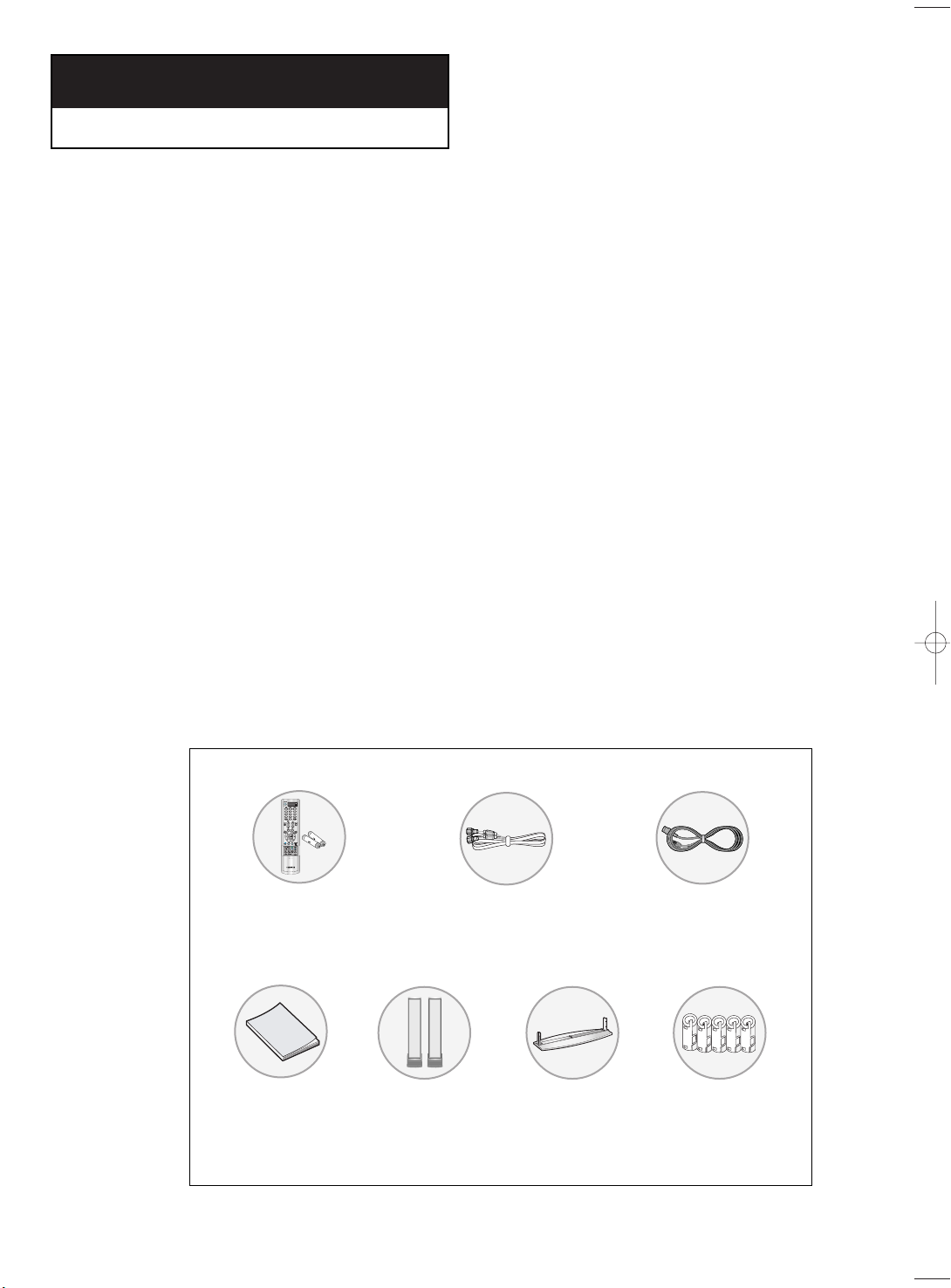
List of Parts
Please make sure the following items are included with your LCD TV.
If any items are missing, contact your dealer.
Remote Control(BN59-00364B)
& Batteries (AAA x 2)
Owner’s
Instructions
(BN96-00568C)
Front
Speaker
RF Cable
(AA39-00039A)
(BN96-00380A)
Stand
Power Cord
(BH39-10339X)
Core(3301-001456)
x 5
English-1
Page 12
YOUR N
EW TV
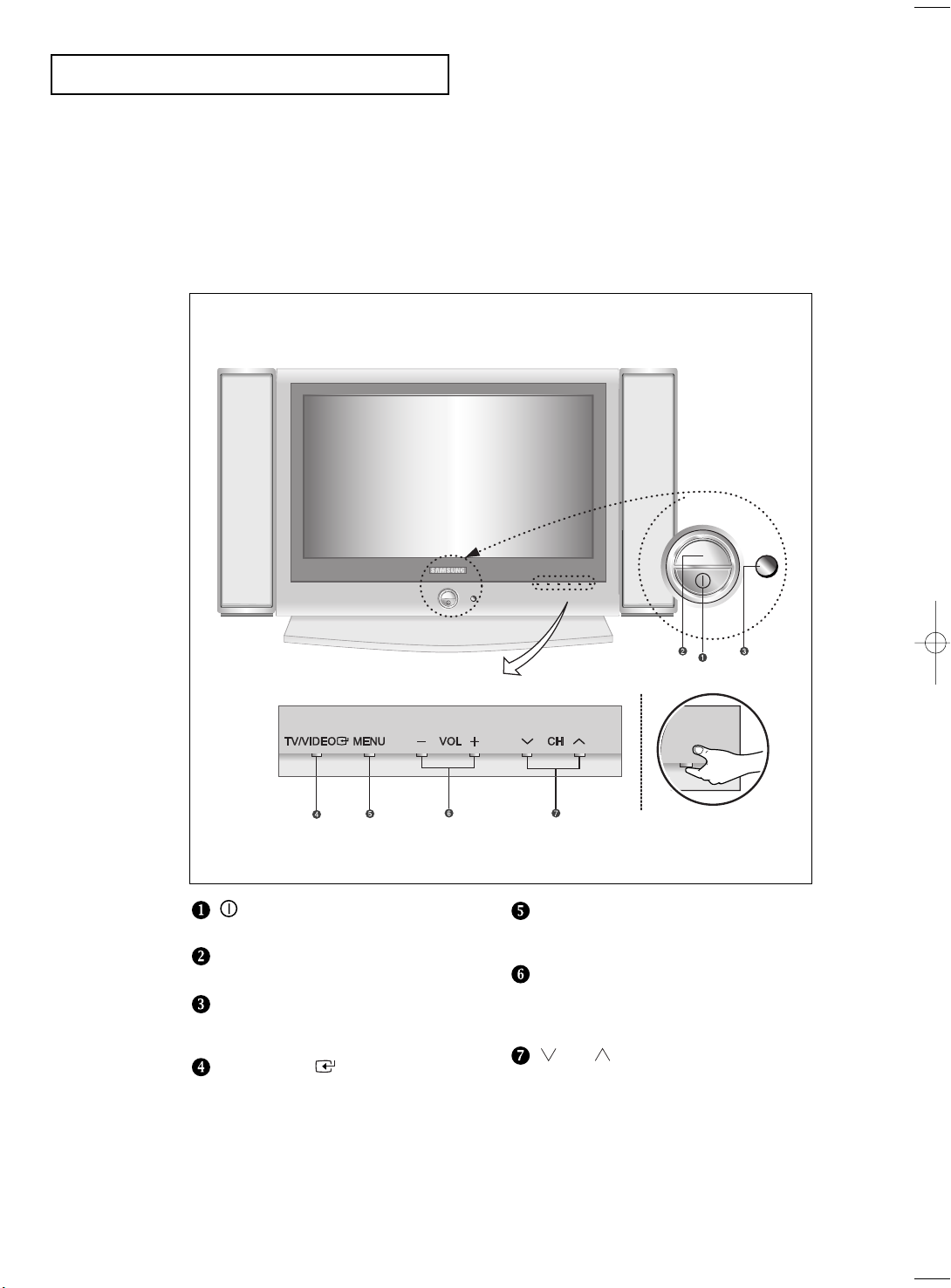
Familiarizing Yourself with Your New TV
Front Panel Buttons
The buttons on the front panel control your TV’s basic features, including the on-screen
menu. To use the more advanced features, you must use the remote control.
POWER
Press to turn the TV on and off.
POWER INDICATOR
Lights up when you turn the power off.
REMOTE CONTROL SENSOR
Aim the remote control towards this spot
on the TV.
TV/VIDEO
Displays a menu of all of the available
input sources (TV, VIDEO1, VIDEO2,
S-VIDEO, Component 1, Component 2,
PC/DVI).
(See Page 17)
English-2
MENU
Press to see an on-screen menu of
your TV’s features.
– VOL +
Press to increase or decrease the volume.
Also used to select items on the
on-screen menu.
CH
Press to change channels.
Also press to highlight various items
on the on-screen menu.
(Without the Remote Control, You can
turn on TV by using the Channel buttons.)
Page 13
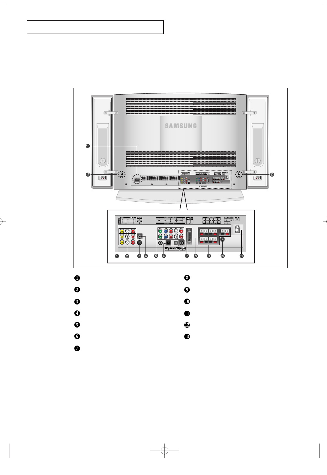
YOUR NEW TV
Rear Panel Jacks
Use the rear panel jacks to connect an A/V component that will be connected
continuously, such as a VCR or a DVD player.
For more information on connecting equipment, see pages 7-15.
VIDEO/AUDIO OUTPUT
VIDEO/AUDIO INPUT
SUPER VIDEO INPUT
HEADPHONE JACK
COMPONENT
DIGITAL AUDIO IN JACK
PC AUDIO INPUT
English-3
PC VIDEO(DVI-D) INPUT
SPEAKER OUT JACK
WOOFER OUTPUT
TV ANTENNA
KENSINGTON LOCK
POWER INPUT
Page 14
YOUR NEW TV
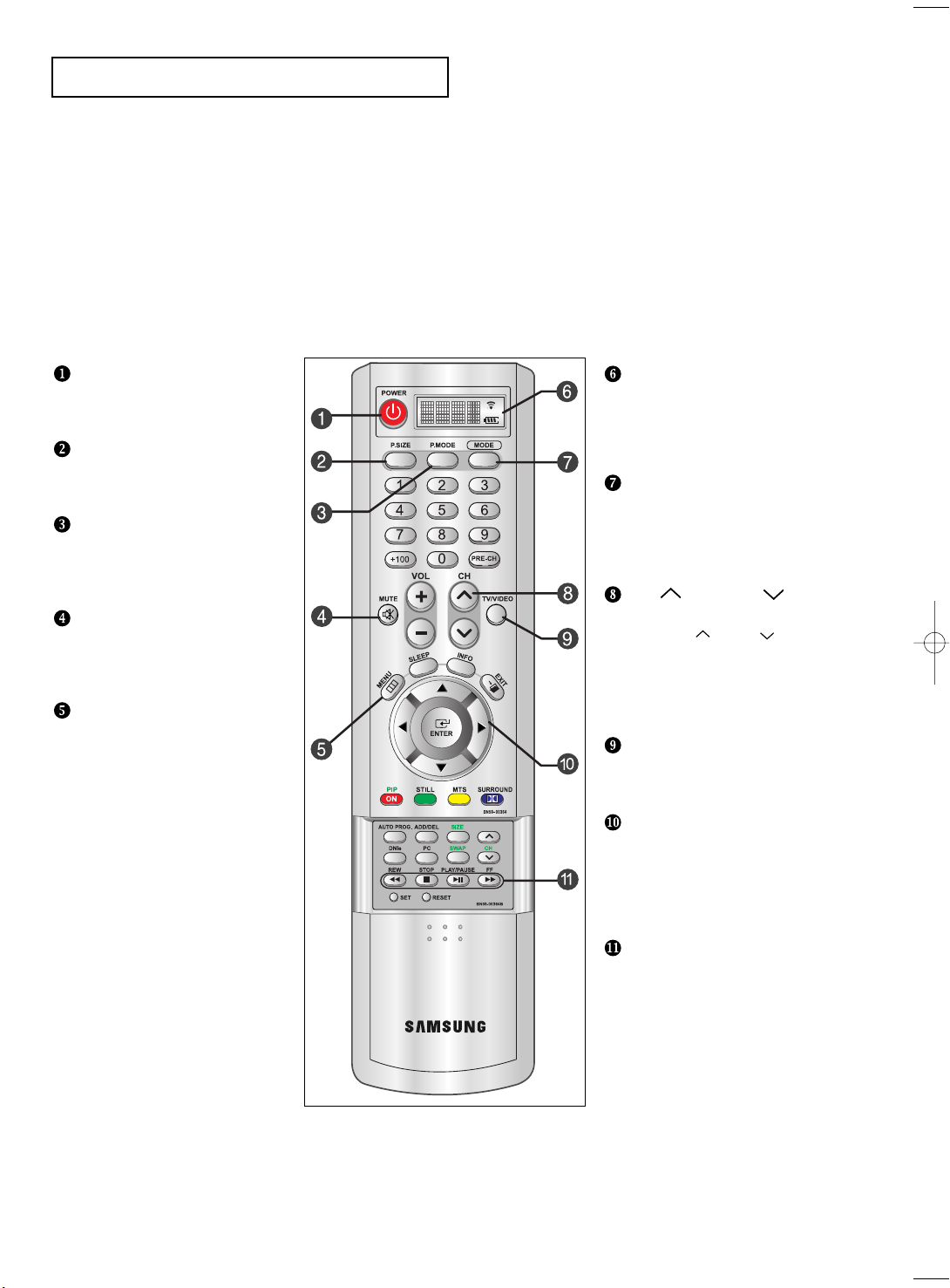
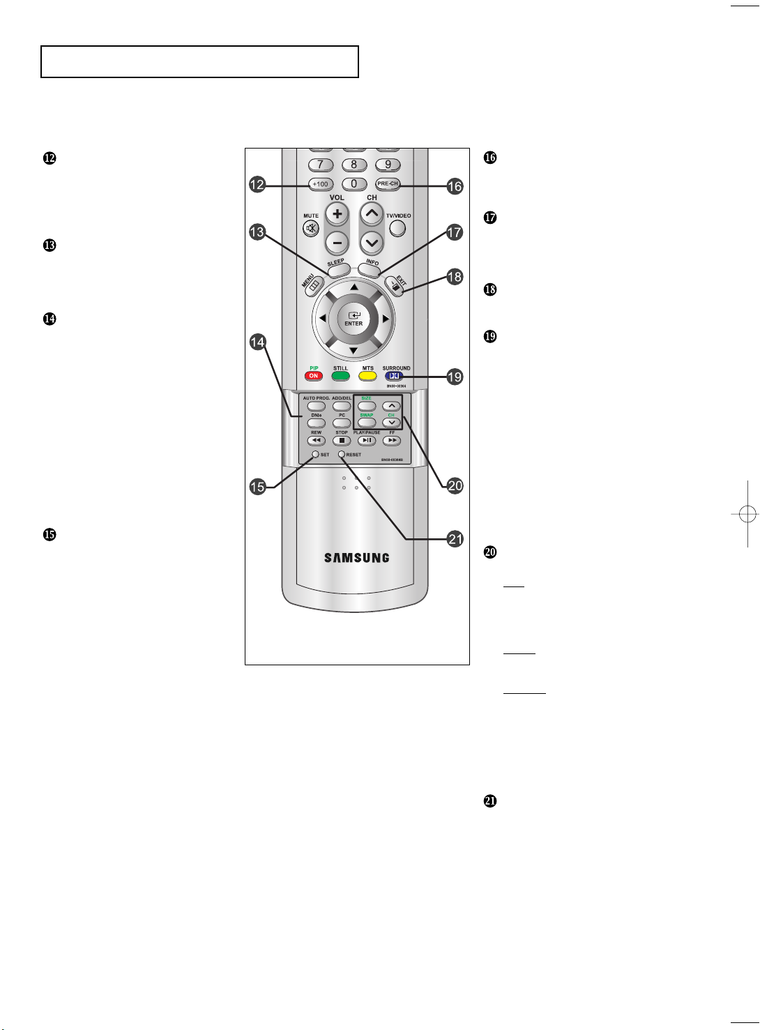
Remote Control
You can use the remote control up to a distance of about 23 feet from the TV. When using the remote,
always point it directly at the TV.
POWER
Turns the TV on and off.
(See Page 16)
P.SIZE
Press to change the screen size.
(See Page 38)
P.MODE
Adjusts the TV picture by selecting
one of the preset factory settings.
(See Page 27)
MUTE
Press to temporarily cut off
the sound.
(See Page 17)
MENU
Displays the main on-screen menu.
(See Page 17)
LCD SCREEN
Shows the battery status and
selected input source device.
Shows the currently selected input
source.
INPUT SELECT BUTTON
Use to select an input source - TV,
Set-top box (Digital Broadcast
Receiver), video, cable or DVD.
(See Page 18-20)
CH and CH
(Channel Up/Down)
Press CH or CH to change
channels.(See Page16)
VOL + and VOL -
Press to increase or decrease
the volume. (See Page 16)
TV/VIDEO
Press to display all of the available
video sources. (See Page 25-26)
JOYSTICK
Use to select on-screen menu
items and change menu values.
(The remote control will only
function with VCR or DVD units
that are compatible with the LCD TV.)
English-4
VIDEO/DVD CONTROL
BUTTON
Use this button to control the video
or DVD functions.
• Works only with compatible VCR
or DVD players.
Page 15
YOUR NEW TV
+100
Press to select channels over 100.
For example, to select channel 121,
press “+100”, then press “2” and “1”.
(See Page 24)
SLEEP TIMER
Press to select a time for the TV to
turn off automatically.
(See Page 54)
AUTOMATIC CHANNEL
BUTTON
Press to automatically store
selected TV/cable channels.
(See Page 24)
ADD/ERASE
Press to add or erase channels
in the TV’s memory.
(See Page 25)
DNIe BUTTON
Press to improve the digital video
quality. (See Page 40)
PC
Press to switch to the PC mode.
SET BUTTON
PRE-CH
Tunes to the previous channel.
(See Page 16)
INFO
Press to display the current channel
and audio/video settings.
(See Page 17)
EXIT
Press to exit the menu.
PIP
See the PIP screen section of this
manual. (See Page 36)
STILL
Press to stop the action during
a particular scene. Press again to
resume normal video.
(See Page 38)
MTS BUTTON
Press to select MONO or STEREO
mode. (See Page 47)
DOLBY DIGITAL BUTTON
Press to enjoy theater-quality 3-D
sound. (See Page 41-45)
PIP CONTROLS
(See Page 37)
CH
Displays the available channels
in sequence.
(These buttons change channels
in the PIP window only.)
SIZE
Press to make the PIP window
double, large or small.
SWAP
Exchanges the video signal that is
currently displayed on the main
screen with the signal in the PIP
window.
(While the main screen is in
PC mode, it does not work.)
English-5
RESET
When your remote does not work,
change the batteries and press the
“Reset” button for 2-3 seconds
before use.
Page 16
YOUR NEW TV
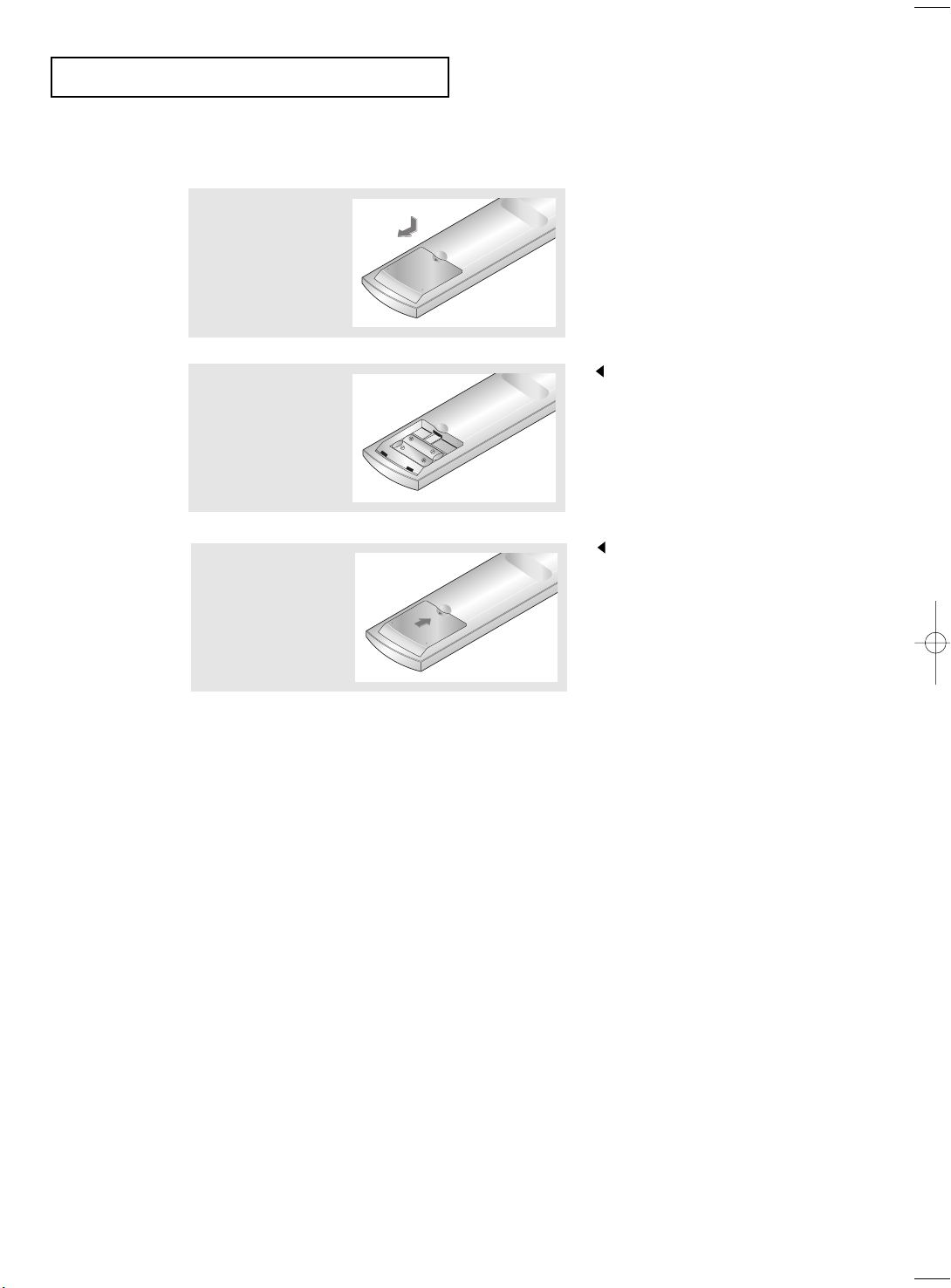
Installing Batteries in the Remote Control
1
Slide the cover out
completely.
2
Install two AAA size
batteries.
3
Replace the cover.
The remote control doesn’t work!
Check the following:
1. Is the TV power switch on?
2. Are the plus and minus ends of the batteries reversed?
3. Did the battery run out?
4. Is the power out, or is the power cord unplugged?
5. Is there a special fluorescent light or a neon sign nearby?
Make sure to match the “+” and
“–” ends of the batteries with the
diagram inside the compartment.
Remove the batteries and store them
in a cool, dry place if you won’t be
using the remote control for a long
time.
The remote control can be used
up to about 23 feet from the TV.
(Assuming typical TV usage,
the batteries last for about one year.)
English-6
Page 17
Chapter Two
INSTALLATION
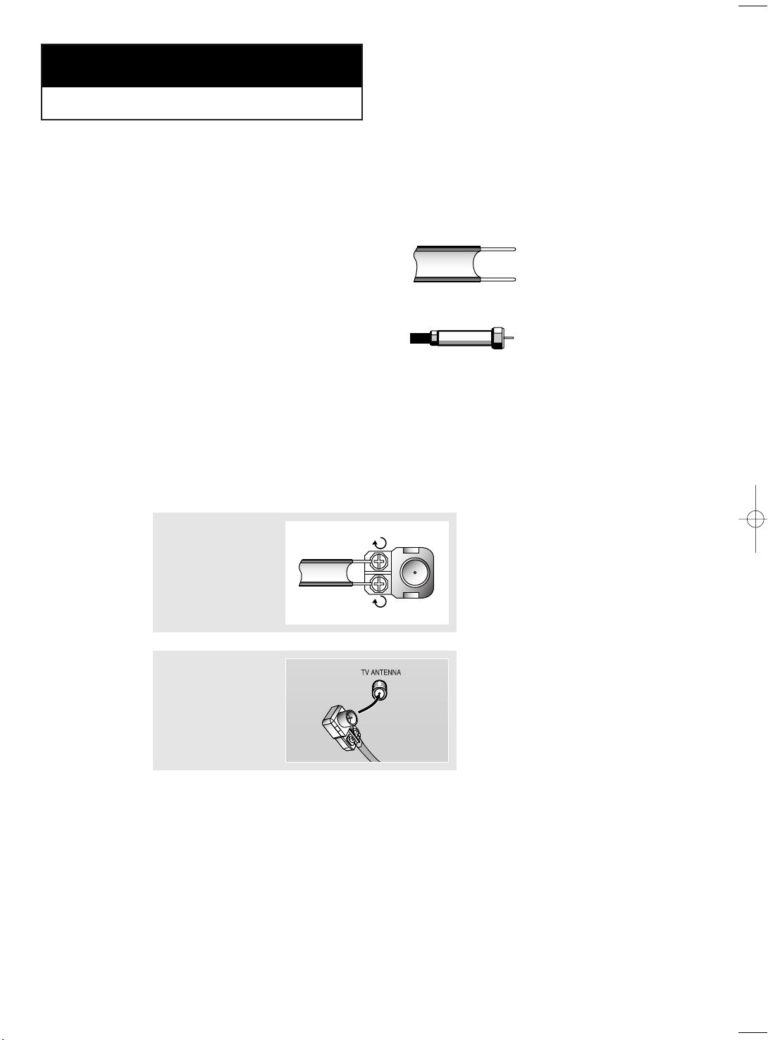
Connecting VHF and UHF Antennas
If your antenna has a set of leads that
look like this, see “Antennas with
300-ohm Flat Twin Leads” below.
If your antenna has one lead that looks
like this, see “Antennas with 75-ohm
Round Leads” on page 8.
If you have two antennas, see “Separate
VHF and UHF Antennas” on page 8.
Antennas with 300-ohm Flat Twin Leads
If you are using an off-air antenna (such as a roof antenna or “rabbit ears”) that has
300-ohm twin flat leads, follow the directions below.
1
Place the wires from
the twin leads under
the screws on a 30075 ohm adaptor (not
supplied). Use a
screwdriver to tighten
the screws.
2
Plug the adaptor into
the TV ANTENNA
terminal on the
bottom of the back
panel.
English-7
Page 18
INSTALLATION
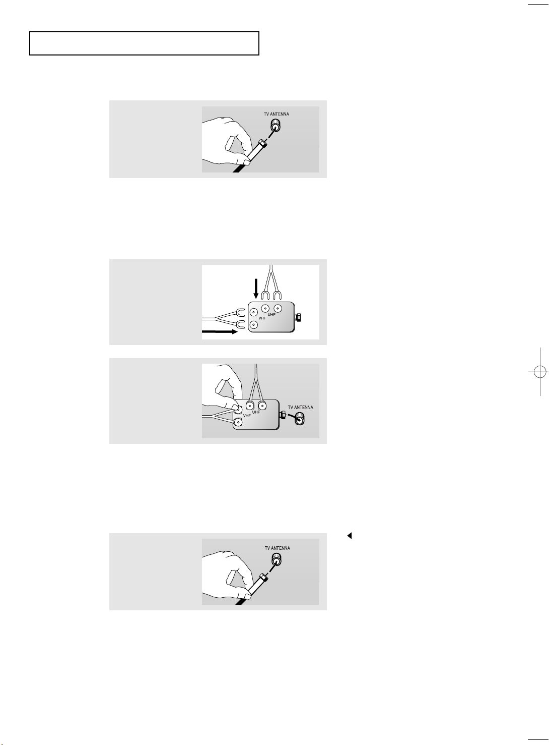
Antennas with 75-ohm Round Leads
1
Plug the antenna
lead into the TV
ANTENNA terminal
on the bottom of the
back panel.
Separate VHF and UHF Antennas
If you have two separate antennas for your TV (one VHF and one UHF), you must
combine the two antenna signals before connecting the antennas to the TV. This
procedure requires a an optional combiner-adaptor (available at most electronics shops).
1
Connect both antenna
leads to the combiner.
2
Plug the combiner
into the TV
ANTENNA terminal
on the bottom of
the rear panel.
Connecting Cable TV
To connect to a cable TV system, follow the instructions below.
Cable without a Cable Box
Because this TV is cable-ready,
1
Plug the incoming
cable into the TV
ANTENNA terminal
on back of the TV.
you do not need a cable box to
view unscrambled cable channels.
English-8
Page 19
INSTALLATION
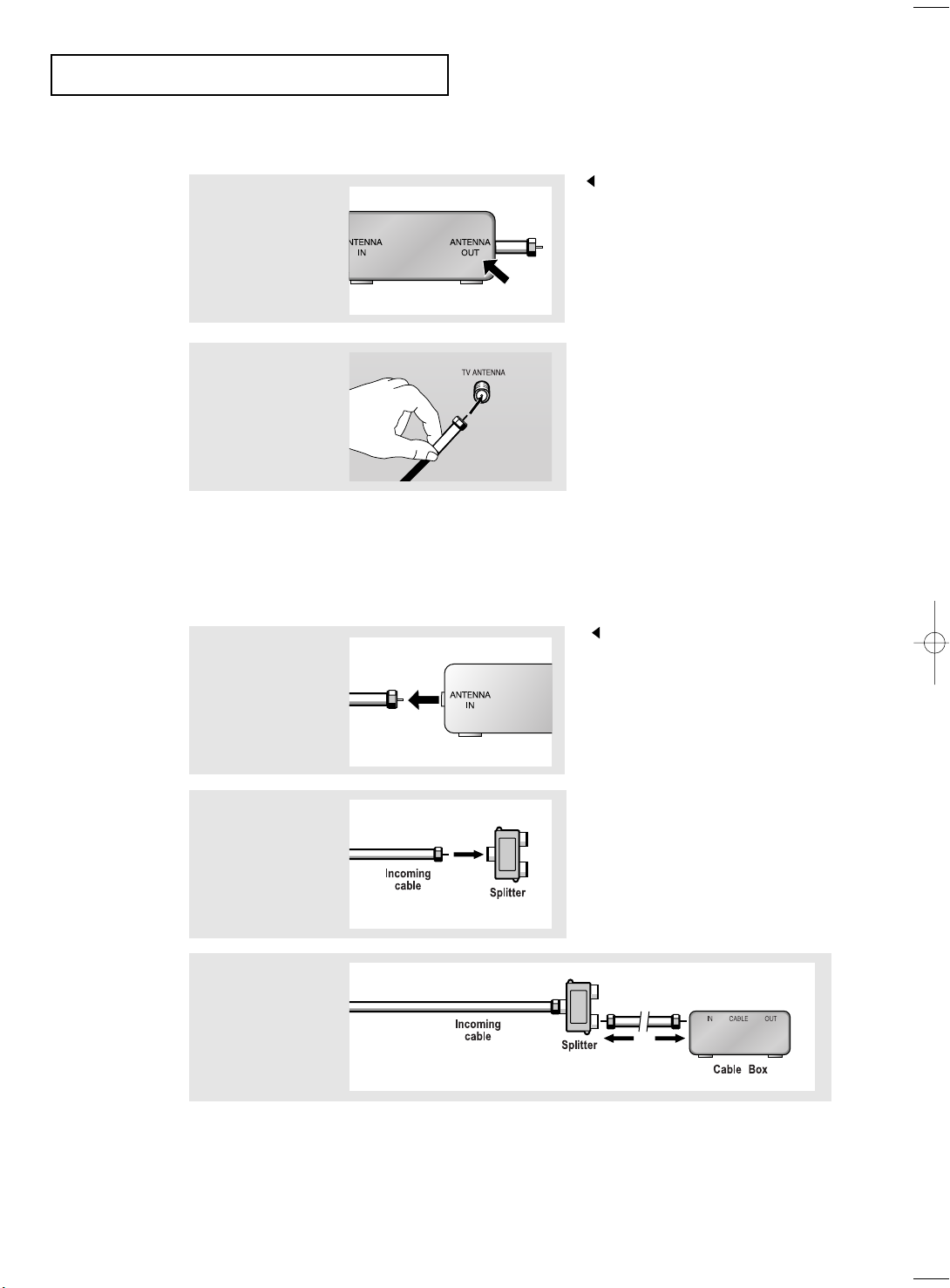
Connecting to a Cable Box that Descrambles All Channels
1
Find the cable that is
connected to the
ANTENNA OUT
terminal on your cable
box.
This terminal might be labeled
“ANT OUT”, “VHF OUT”, or
simply, “OUT”.
2
Connect the other end
of this cable to the TV
ANTENNA terminal on
the back of the TV.
Connecting to a Cable Box that Descrambles Some Channels
If your cable box descrambles only some channels (such as premium channels), follow the
instructions below. You will need a two-way splitter, an RF (A/B) switch, and four lengths
of coaxial cable. (These items are available at most electronics stores.)
1
Find and disconnect
the cable that is
connected to the
ANTENNA IN terminal
on your cable box.
This terminal might be labeled
“ANT IN”, “VHF IN”, or simply,
“IN”.
2
Connect this cable
to a two-way splitter.
3
Connect a coaxial
cable between an
OUTPUT terminal on
the splitter and the IN
terminal on the cable
box.
English-9
Page 20
INSTALLATION
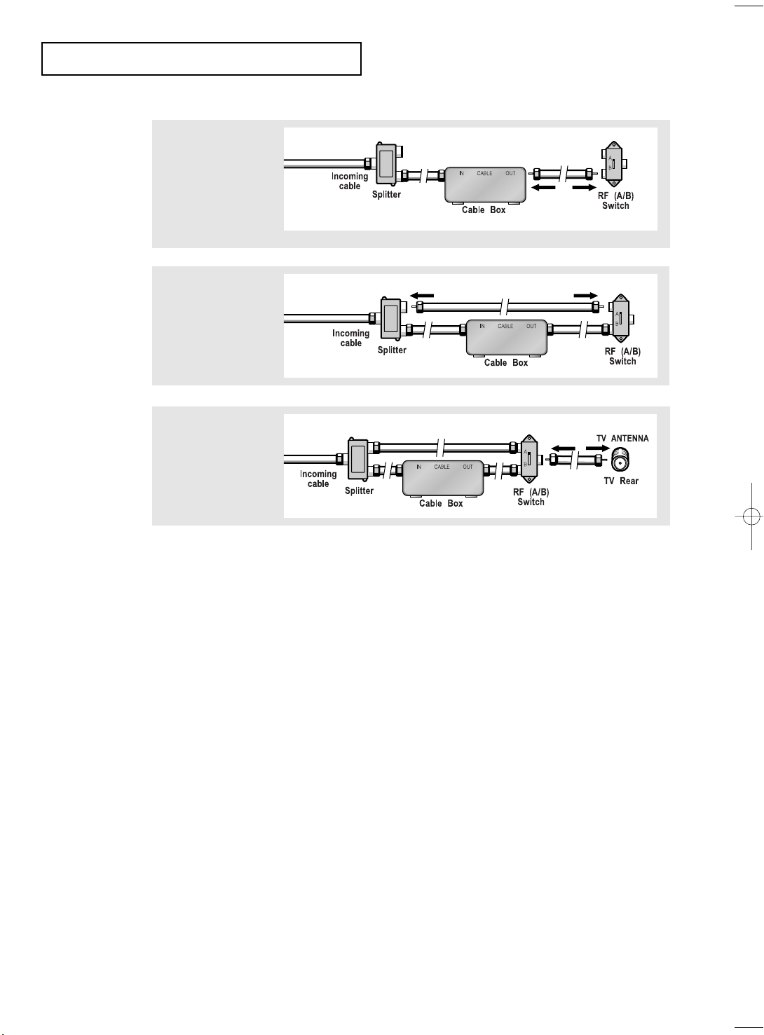
4
Connect a coaxial
cable between the
ANTENNA OUT
terminal on the
cable box and the
B–IN terminal on the
A/B switch.
5
Connect another
cable between the
other OUT terminal
on the splitter and
the A–IN terminal on
the RF (A/B) switch.
6
Connect the last
coaxial cable
between the OUT
terminal on the RF
(A/B) switch and the
VHF/UHF terminal
on the rear of the
TV.
After you’ve made this connection, set the A/B switch to the “A” position for normal
viewing. Set the A/B switch to the “B” position to view scrambled channels.
(When you set the A/B switch to “B,” you will need to tune your TV to the cable box’s
output channel, which is usually channel 3 or 4.)
English-10
Page 21
INSTALLATION
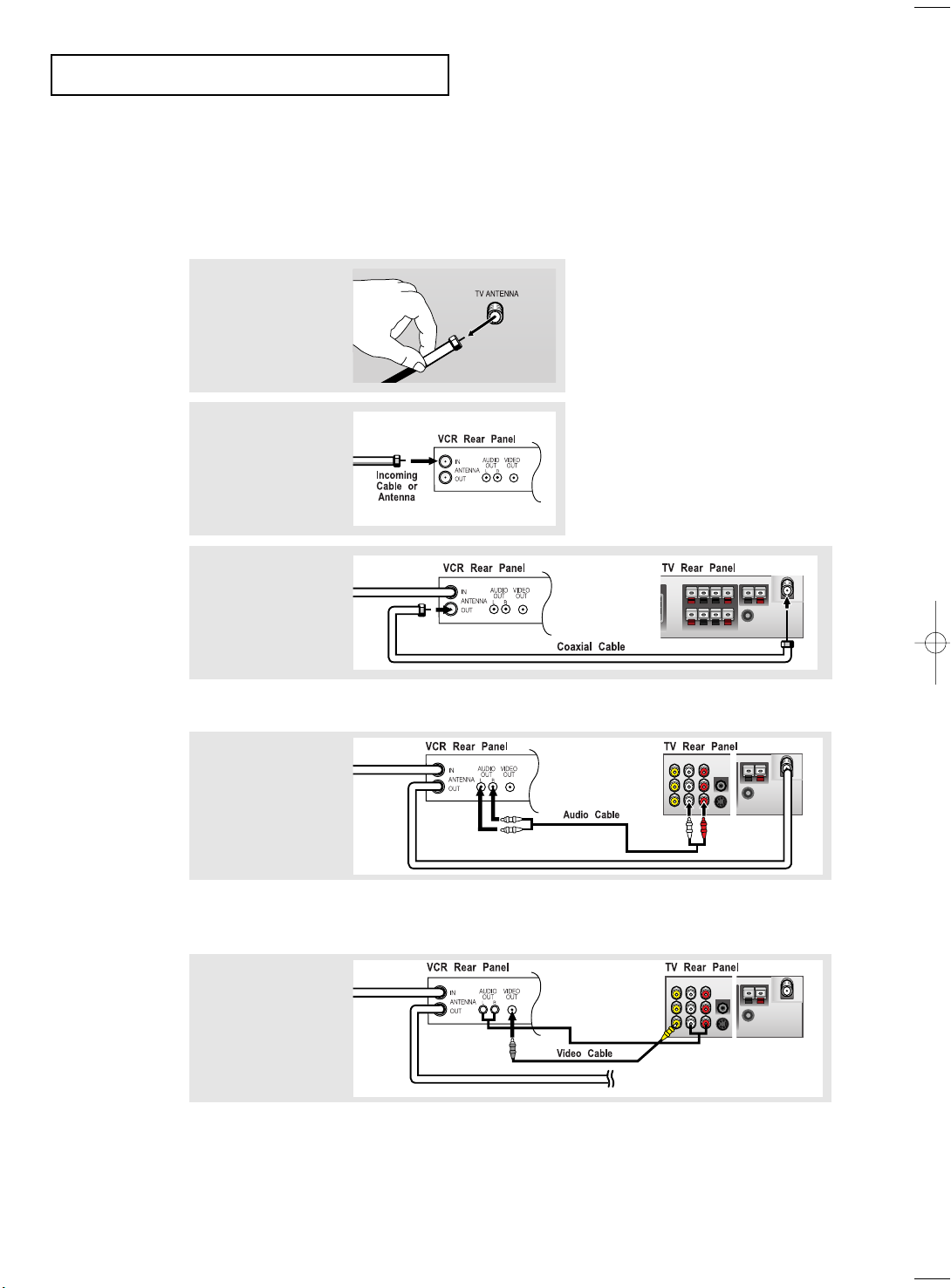
Connecting a VCR
These instructions assume that you have already connected your TV to an antenna or a
cable TV system (according to the instructions on pages 7-10).
Skip step 1 if you have not yet connected to an antenna or a cable system.
1
Unplug the cable or
antenna from the
back of the TV.
2
Connect the cable or
antenna to the
ANTENNA IN terminal
on the back of the
VCR.
3
Connect a coaxial
cable between the
ANTENNA OUT
terminal on the VCR
and the antenna
terminal on the TV.
A coaxial cable is usually included with a VCR. (If not, check your local electronics store).
4
Connect a set of
audio cables
between the AUDIO
OUT jacks on the
VCR and the AUDIO
jacks on the TV.
If you have a “mono” (non-stereo) VCR, use the Y-connector (not supplied) to hook
up to the left and right audio input jacks of the TV. If your VCR is stereo, you must
connect two cables.
5
Connect a video
cable between the
VIDEO OUT jack on
the VCR and the
VIDEO jack on the
TV.
Follow the instructions in “Viewing a VCR or Camcorder Tape” to view your VCR tape.
# Each external input source device has a different back panel configuration.
English-11
Page 22
INSTALLATION
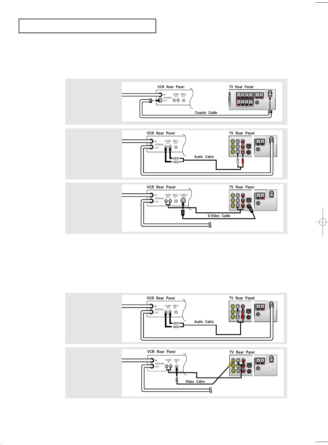
Connecting an S-VHS VCR
Your Samsung TV can be connected to an S-Video signal from an S-VHS VCR.
(This connection delivers a better picture as compared to a standard VHS VCR.)
1
To begin, follow
steps 1–3 in the
previous section to
connect the antenna
or cable to your
VCR and your TV.
2
Connect a set of audio
cables between the
AUDIO OUT jacks on
the VCR and the
AUDIO INPUT jacks
on the TV.
3
Connect an S-video
cable between the
S-VIDEO OUT jack on
the VCR and the
S-VIDEO INPUT jack
on the TV.
An S-video cable is usually included with an S-VHS VCR.
(If not, check your local electronics store.)
# Each external input source device has a different back panel configuration.
Connecting an External Input Source
Connect the Input/AUDIO cables to the Input/AUDIO OUT jacks on the TV and the
Input/AUDIO IN jacks on the VCR (Connect the cables to the jacks of the same color.)
1
Connect a set of
audio cables
between the AUDIO
IN jacks on the VCR
and the AUDIO
jacks on the TV.
2
Connect a video
cable between the
VIDEO IN jack on
the VCR and the
VIDEO jack on the
TV.
Make sure that the output is set to TV. (See Page 33)
# Each external input source device has a different back panel configuration.
English-12
Page 23
INSTALLATION
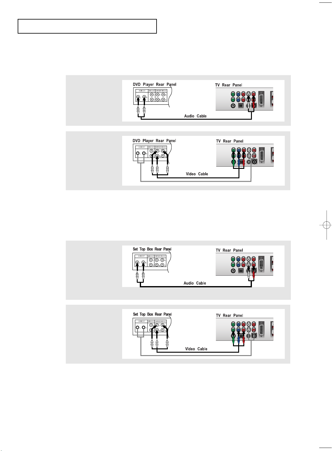
Connecting a DVD Player
The rear panel jacks on your TV make it easy to connect a DVD player to your TV.
1
Connect a set of audio
cables between the
L, R AUDIO INPUT
jacks on the TV and
the AUDIO OUT jacks
on the DVD player.
2
Connect a video cable
between the
COMPONENT1 or
COMPONENT2
(Y, Pb, Pr) jacks on
the TV and the Y, Pb,
Pr jacks on the DVD
player.
Note: For an explanation of Component video, see your DVD player owner's manual.
# Each external input source device has a different back panel configuration.
Connecting a Digital TV Set-Top Box
The connections for a typical set-top box are shown below.
1
Connect a set of audio
cables between the
L, R COMPONENT1
or COMPONENT2
AUDIO INPUT jacks
on the TV and the
AUDIO OUT jacks on
the Set-Top Box.
2
Connect a video cable
between the
COMPONENT1 or
COMPONENT2
(Y, Pb, Pr) jacks on
the TV and the Y, Pb,
Pr jacks on the
Set-Top Box.
Note: For an explanation of Component video, see your Set-Top Box owner's manual.
# Each external input source device has a different back panel configuration.
English-13
Page 24
INSTALLATION
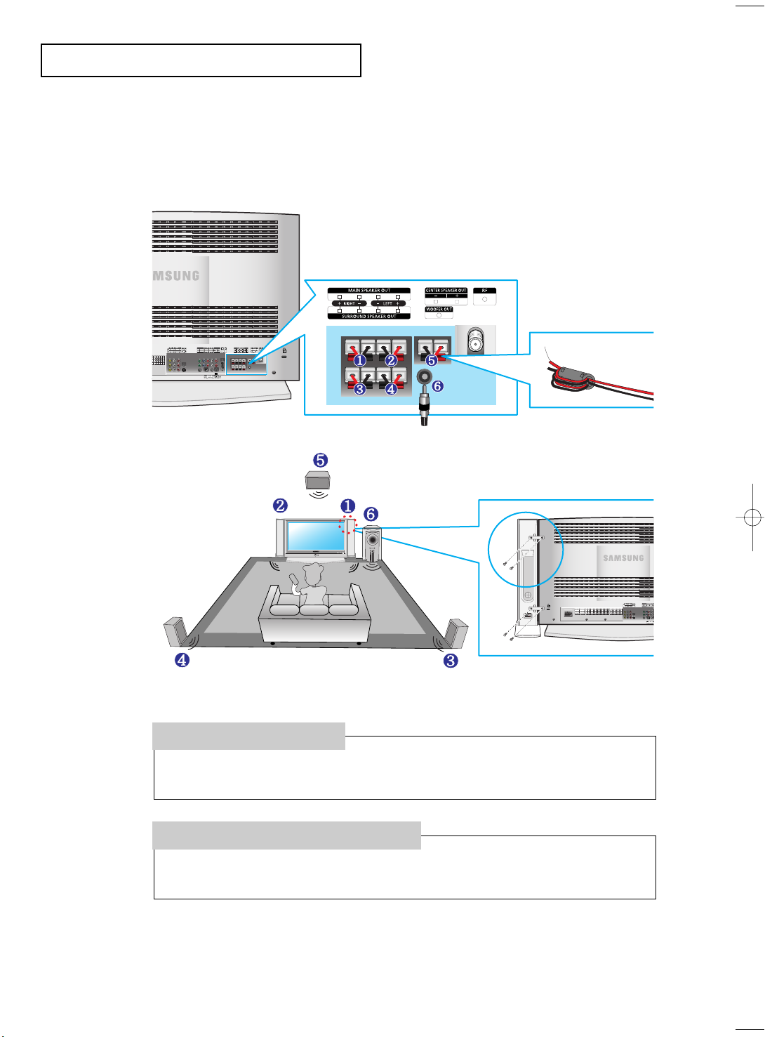
Connecting the Speakers
5.1. Channel system: 5 Channels – 2 Channels for the front (left and right),
1 Channel for the center,
2 for the rear (left and right)
0.1 Channel –Subwoofer Channel
•Wind the speaker
cable on the core
twice or more.
1. Place the hooks on the
speaker and the TV set.
2. Tighten the screws to
secure the hooks.
How to Connect
1. Connect the speaker cables to the Speaker OUT jacks on the TV and the IN jacks on the speakers.
2. Connect the Subwoofer OUT jack on the TV to the Subwoofer.
How to Turn the Sound On
1. Turn the TV on and press the TV/Input button to select TV.
2. Press the Volume button to adjust the volume level.
• The center, rear (left and right) and the Subwoofer speakers are sold separately.
• Contact the nearest electronics store to purchase them.
English-14
Page 25
INSTALLATION
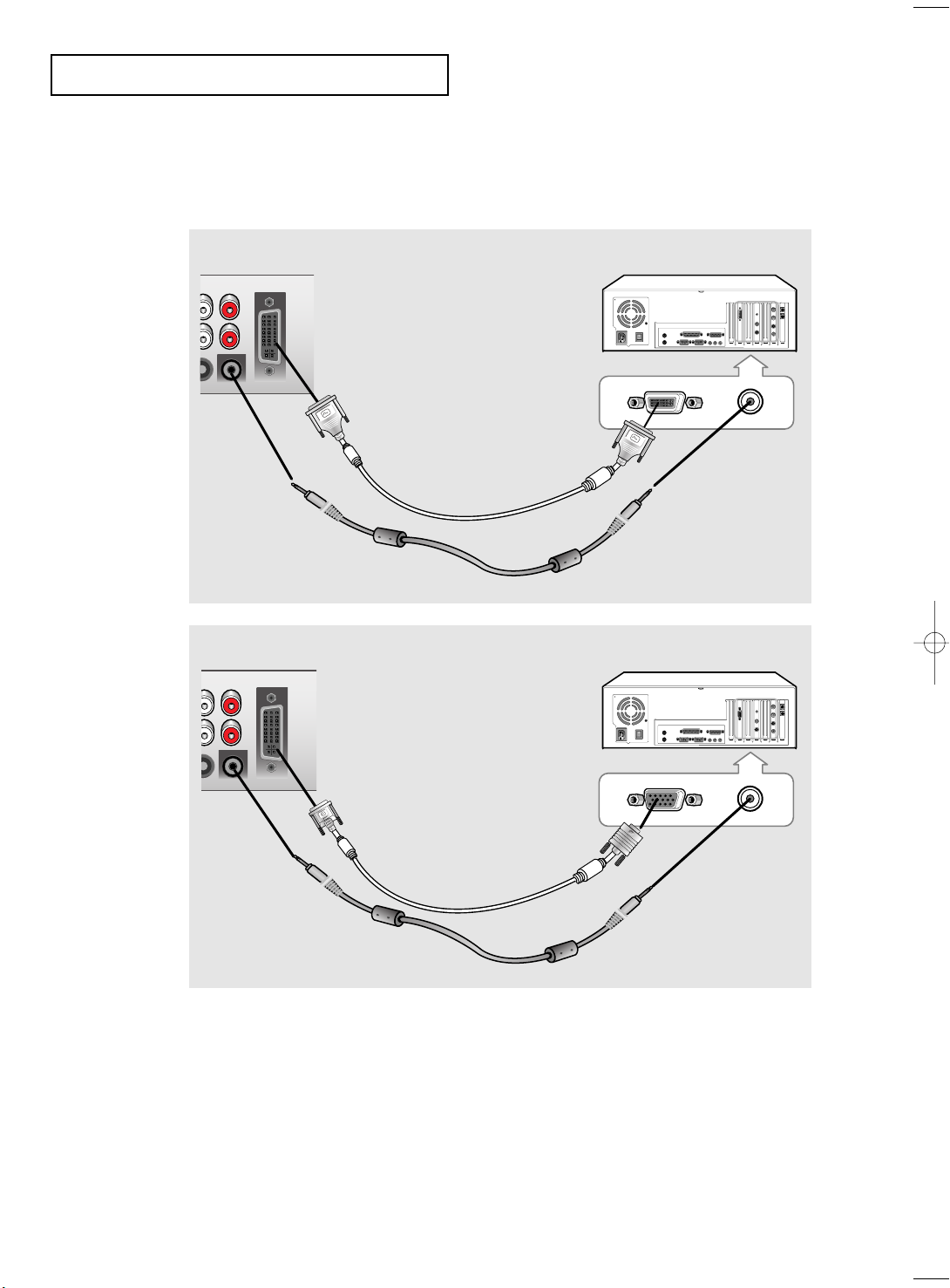
PC VIDEO CABLE
( DVI-D+DVI-D )
PC AUDIO CABLE
Connecting a PC
Note: This figure shows the Standard Connector-jack panel. The actual configuration on
your TV may be different, depending on the model.
DVI-D
TV rear panel PC rear
D-SUB
TV rear panel PC rear
PC VIDEO CABLE
( DVI + D-SUB)
PC AUDIO CABLE
• PC AUDIO INPUT
Connect these to the audio-output jacks on your PC.
• PC VIDEO INPUT
Connect to the video output port on your PC.
# Each external input source device has a different back panel configuration.
English-15
Page 26

Chapter Three
SPECIAL FEATURES
Turning the TV On and Off
Press the POWER button.
You can also use the Power button on the front panel.
[Note]
1. Use of the 'Power' button on the remote is possible only when the TV is
in 'Power Saving' (stand-by) mode. If the TV is powered off,
the remote cannot be used to turn the TV on.
2. To retain the time and or automatic alarm settings, always put the TV
in stand-by mode with the remote control.
Use of the power switch on the TV will clear all time related settings.
[Benefit] This full 'power off' function is as effective as unplugging the power cable.
TV switches to stand-by mode when powered off by the remote control.
To return power ( ) to the screen, press the remote control 'ON' or channel button
( ). Pressing the power button on the TV does not return power to the screen
because in this case, the TV restores the last mode, which was 'Power Saving'.
Changing Channels
Using the Channel Buttons
1
Press the CH
When you press the CH
You will see all the channels that the TV has memorized. (The TV must have
memorized at least three channels.) You will not see channels that were either erased
or not memorized.
Using the PRE-CH Button to select the Previous Channel
buttons to change channels.
/
buttons, the TV changes channels in sequence.
/
1
Press the PRE-CH button.
The TV will switch to the last channel viewed.
To quickly switch between two channels that are far apart, tune to one channel,
then use the number button to select the second channel. Then, use the PRE-CH
button to quickly alternate between them.
Adjusting the Volume
1
Press the VOL +/– buttons to increase or decrease the volume.
English-16
Page 27

SPECIAL FEATURES
Using Mute
At any time, you can temporarily cut off the sound using the Mute button.
1
Press MUTE and the sound cuts off.
The word “ ” will appear in the lower-left corner of the screen.
2
To turn mute off, press the MUTE button again, or simply
press the VOL +/– button.
Viewing the Display
The display identifies the current channel and the status
of certain audio-video settings.
1
Press the Display button on
the remote control.
The TV will display the
channel, the type of sound,
and the status of certain
picture and sound settings.
The on-screen displays
disappear after about ten seconds.
Press the button once more or wait
approximately 10 seconds and it
disappears automatically.
Allows the user to adjust the
settings according to his/her prefer
ence and shows the current
settings.
Viewing the Menus
1
With the power on, press the
MENU button.
The main menu appears on the
screen. It’s left side has five
icons:
Input, Picture, Sound, Channel,
Setup.
2
Use the UP/DOWN buttons to select one of the
5 icons. Then press ENTER or RIGHT to access the
icon’s sub-menu.
3
Press the MENU button to exit.
English-17
The on-screen menus
disappear from the screen after
about thirty seconds.
You can also use the MENU,
CHANNEL, VOLUME and
TV/Video buttons on the control
panel of the TV to make selections.
Page 28

SPECIAL FEATURES
Setting Up Your Remote Control
After it has been set up properly, your remote control can operate in four different modes:
TV, VCR, Cable, or DVD. Pressing the corresponding button on the remote control allows
you to switch between these modes, and control whichever piece of equipment you choose.
Note
The remote control might not be compatible with all DVD Players, VCRs and Cable boxes.
Setting Up the Remote to Operate Your VCR
1Turn off your VCR.
2Press the MODE button and make sure that the VCR LED
is illuminated.
3Press the Set button on your TV’s remote control.
4Using the number buttons on your remote control, enter
three digits of the VCR code listed on page 21 of this
manual for your brand of VCR. Make sure you enter three
digits of the code, even if the first digit is a “0”.
(If more than one code is listed, try the first one.)
5Press the Power button on the remote control. Your VCR
should turn on if your remote is set up correctly.
If your VCR does not turn on after set up, repeat steps
2, 3, and 4, but try one of the other codes listed for your
brand of VCR. If no other codes are listed, try each VCR
code, 000 through 089.
Note on Using Remote Control Modes: VCR
When your remote control is in “VCR” mode, the volume buttons still control your TV’s volume.
English-18
Page 29

Setting Up the Remote to Operate Your Cable Box
1Turn off your cable box.
2Press the MODE button and make sure that the Cable LED is
illuminated.
3Press the SET button on your TV’s remote control.
4Using the number buttons on your remote control, enter three
digits of the cable box code listed on page 21 of this manual
for your brand of cable box. Make sure you enter three digits
of the code, even if the first digit is a “0.”
If there is more than one code listed, try the first one.
5Press the Power button on the remote control. Your cable box
should turn on if your remote is set up correctly.
If your cable box does not turn on after set up, repeat steps
2, 3, and 4, but try one of the other codes listed for your brand
of cable box. If no other codes are listed, try each code, 000
through 077.
Note on Using Remote Control Modes: Cable Box
When your remote control is in “Cable Box” mode, the volume buttons still control your TV’s volume.
English-19
Page 30

Setting Up the Remote to Operate Your DVD
Setting Up the Remote to Operate Your DVD
1Turn off your DVD.
2Press the MODE button and make sure that the DVD LED is
illuminated.
3Press the SET button on your TV’s remote control.
4Using the number buttons on your remote control, enter three
digits of the DVD code listed on page 21 of this manual for
your brand of DVD. Make sure you enter three digits of the
code, even if the first digit is a “0.”
If there is more than one code listed, try the first one.
5Press the Power button on the remote control. Your DVD should
turn on if your remote is set up correctly.
If your DVD does not turn on after set up, repeat steps 2, 3, and
4, but try one of the other codes listed for your brand of DVD.
If no other codes are list-ed, try each code, 000 through 008.
Note on Using Remote Control Modes: DVD
When your remote control is in “DVD” mode, the volume buttons still control your TV’s volume.
English-20
Page 31

Remote Control Codes
VCR Codes
Admiral
Aiwa
Audio Dynamics
Bell&Howell
Broksonic
Candle
Canon
Citizen
Colortyme
Craig
Curtis-Mathes
Daewoo
DBX
Dimensia
Dynatech
Electrohome
Emerson
Fisher
Funai
GE
Go Video
Harman Kardon
Hitach
Instant Replay
JC Penney
JCL
JVC
kenwood
009,016,017,023,024,055,062,073,076
003,004,005,006,007,008,022,054,085
017,018,019,022,024,029,032,036,043,
050,051,056,058,066,071,074,076,077,079
011,021,027,028,052,057,067
011,014,016,017,023,025,039,044,060,062
KLH
015,088
LG
024
Lloyd
022,025
Logik
011
LXI
019
016,018,022,054,055,061
016,018,022,054,055,061
014,024,044,045
011,017,023,025,039,055
011,023,025,039,055
Magnavox
Marantz
017,062
Marta
023
MEI
016,021
Memorex
MGA
Midland
Minota
009
Mitsubishi
024
Montgomery ward
036
MTC
Multitech
NEC
Optimus
024
Panasonic
Pentax
016
Pentex Reserch+
023
Philco
Philips
017
Pioneer
Portland
ProScan
Quartz
Quasar
Radio Shack/Realistics
001,002,007
017,038,062,065
011,017,023,025,038,039,055,070
016,024,040,041
011,023,025,039,055,070,073
017,062,084,086
017,038,062,065
014,025,042,059
053,054,061
011,015,017,018,021,
024,028,036,052,062
024
040
024
016,024
015
014,044
055
017,038
009
011
017,053
Samsung
Sansui
Sanyo
Scott
Sears
Sharp
Shintom
Signature
Sony
Sylvania
Symphonic
Tandy
Tashiko
Tatung
Teac
Technics
Temika
TMK
Toshiba
Totevision
Unitech
Vector Research
Victor
Video Concepts
Videosonic
Wards
Yamaha
Zenith
RCA
082
009,014,016,017,037,044,046,063,078
000,016,022,031,041,051
025
011,021
022,050,058,077
011,014,018,021,027,028,044,052,057
015,036,048,054
026,035,040,064
024
026,035,047
017,024,038,062,065
024
011,024
039
024,039,078
017
076
014,022,028,057,058
016,018
Cable Box Codes
Anvision
Cable star
Eagle
Eastrm Int.
General Instrument
GI
Hamlin
Hitachi
012,013,023,031,032,033,038,044,054,070,073
Jerrold
Macom
Magnavox
015,016,027,029,034,036,037,040,041,048,049
012,013,023,031,032,
033,038,044,075,076,077
011,012,020,021,042,056
DVD Codes
Philips
Proscan
RCA
Toshiba
Panasonic
Sony
Samsung
015,016
015,016
015,016
054
045,051,054
045,051
007
008
008
002
006
004
000
NSC
Oak
Osk Sigma
Panasonic
Philips
015,016,027,029,034,036,037,040,041,048,049
Pioneer
Randtek
RCA
Regal
Regency
SA
Samsung
011,035,047,069
000,011,030,052,071,072
English-21
017
024,046
024
026,028,052
015,016
008,035,074
011,020,021
010,041
Signature
Sprucer
Starcom
Stargate 2000
Sylvania
Texscan
Tocom
Unika
Universal
Viewstar
015,016,027,029,034,036,037,040,041,048,049
Warner Amex
Zenith
025,029,057,058,063
039,040,049
022,050,065,069
054
035
054
066
019,067
019,067
059,060
052
Page 32

Chapter Four
OPERATION
Plug & Play Feature
When the TV is initially powered On, two basic customer settings proceed
automatically and subsequently: Setting Auto program, Clock.
1
Press the POWER
button on the remote control.
The message “Plug & Play”
is displayed.
2
Press the ENTER button.
The TV will begin
memorizing all of the
available channels.
3
Press the LEFT/RIGHT
buttons to move to the hour
or minute.
Set the hour or minute by
pressing the UP/DOWN
buttons.
(refer to “Setting and
Displaying the Current Time”
on page 51.)
4
The message “Enjoy your
watching.” is displayed.
English-22
Page 33
OPERATION
Memorizing the Channels
Your TV can memorize and store all of the available channels for both “off-air” (antenna)
and cable channels. After the available channels are memorized, use the CH and CH
buttons to scan through the channels. This eliminates the need to change channels by
entering the channel digits. There are three steps for memorizing channels: selecting a
broadcast source, memorizing the channels (automatic) and adding and deleting channels
(manual).
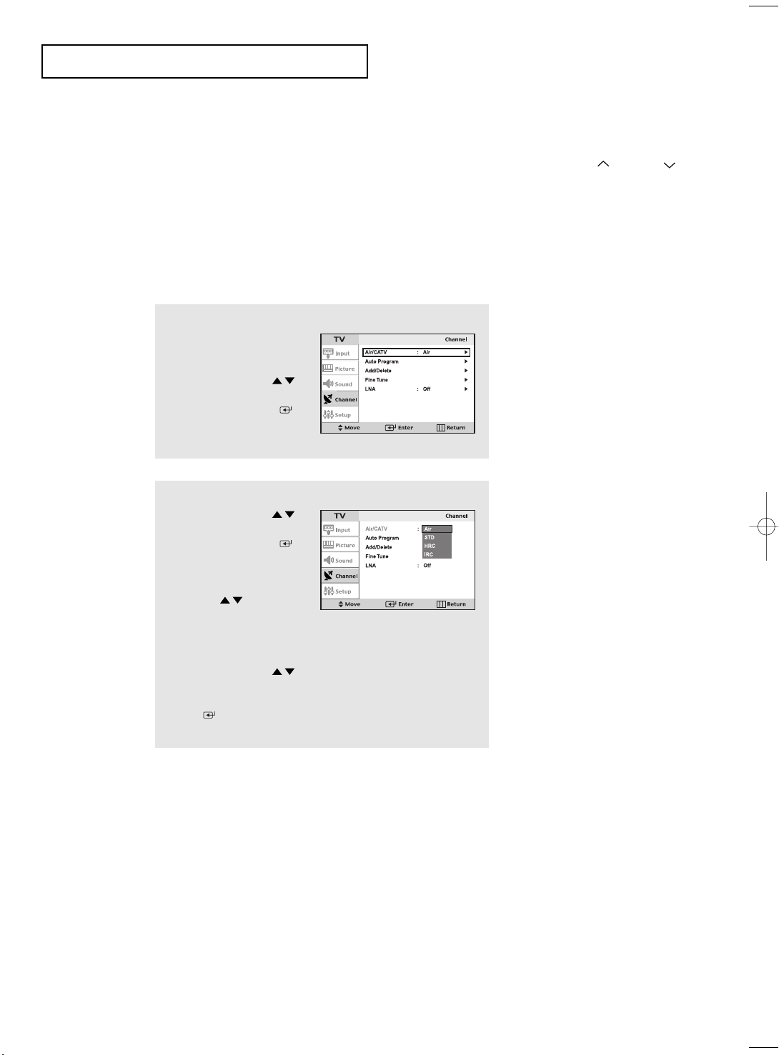
Selecting the Video Signal-source
Before your television can begin memorizing the available channels, you must specify the
type of signal source that is connected to the TV (i.e., an antenna or a cable system).
1
Press the MENU button to
display the menu.
Press the UP/DOWN
buttons to select “Channel”,
then press the ENTER
button.
2
Press the UP/DOWN
buttons to select “Air/CATV”,
then press the ENTER
button.
Repeatedly press the
UP/DOWN buttons to
cycle through these choices:
Air (antenna), STD, HRC or IRC
(all cable TV).
Press the UP/DOWN
buttons to select the Video
signal source, then press the
ENTER button.
Note : STD, HRC and IRC identify various types of cable
TV systems. Contact your local cable company to identify the
type of cable system that exists in your particular area.
At this point the signal source has been selected.
Proceed to “Storing Channels in Memory” (next page).
English-23
Page 34

OPERATION
Storing Channels in Memory
(Automatic Method)
1
First, select the correct signal
source (Air, STD, HRC, IRC).
See steps 1~2 on previous
page.
Press the MENU button.
Press the UP/DOWN
buttons to select “Channel”,
then press the ENTER
button.
2
Press the UP/DOWN
buttons to select
“Auto program”.
Press the ENTER button.
3
Press the LEFT/RIGHT
buttons to select “Start”.
Press the ENTER button.
The TV will begin memorizing
all of the available channels.
4
After all the available
channels are stored, the Auto
program menu reappears.
Press the MENU button to
exit.
To select channels over 100,
Ex) Press
➔➔
to select cable channel 108.
The TV automatically cycles
through all of the available
channels and stores them in
memory. This takes about one to
two minutes.
Press
ENTER at any time to
interrupt the memorization process
and return to the CHANNEL menu.
English-24
Page 35

OPERATION
Adding and Erasing Channels (Manual Method)
1
Use the number buttons to
directly select the channel
that will be Add or Delete.
Press the MENU button to
display the menu.
Press the UP/DOWN
buttons to select “Channel”,
then press the ENTER
button.
Press the UP/DOWN
buttons to select “Add/Delete”.
Press the ENTER button.
Press the ENTER to select
“Add and Delete”.
Press the MENU button to exit.
2
Use the number buttons to directly select the channel that will be added or
erased.
Press the ADD/ERASE button.
Repeatedly pressing this button will alternate between “Added” and “Erased.”
You can view any channel (including an erased channel) by using the number
buttons on the remote control.
To Select TV/Input
Use to select TV or other external input source connected to the TV.
Use to select the screen of your choice.
1
Press the MENU button to
display the on-screen menu.
Press the UP/DOWN
buttons to select “Input”.
Press the ENTER button.
2
Press the ENTER button
to select “TV”, then press the
ENTER button.
3
Press the UP/DOWN
buttons to select the input
source, then press the
ENTER button.
Press the MENU button to exit.
English-25
Page 36

OPERATION
To Edit the Input Source Name
Name the input device connected to the input jacks to make your input source selection easier.
1
Press the MENU button to
display the on-screen menu.
Press the UP/DOWN
buttons to select “Input”,
then press the ENTER
button.
Press the UP/DOWN
buttons to select “Edit Name”,
then press the ENTER
button.
2
Press the UP/DOWN
buttons to select
“Video1”, “Video2”,
“S-Video”, “Component1”,
“Component2” or “PC/DVI”,
then press the ENTER
button.
3
Press the
buttons repeatedly until the
correct VCR appears.
After the VCR is entered,
press the
UP/DOWN
ENTER
button.
English-26
Page 37

OPERATION
Using Automatic Picture Settings
Your TV has four automatic picture settings (“Custom”, “Dynamic”, “Standard”, and
“Movie”) that are preset at the factory. You can activate either Custom, Dynamic,
Standard, or Movie by pressing P.MODE (or by making a selection from the menu). Or,
you can select “Custom” which automatically recalls your personalized picture settings.
1
Press the MENU button to
display the menu.
Press the UP/DOWN
buttons to select “Picture”,
then press the ENTER
button.
Press the ENTER button.
2
Press the UP/DOWN
buttons to select the
“Dynamic”, “Standard”,
“Movie” or “Custom”
picture setting.
Press the ENTER button.
Press MENU twice to exit.
Alternate method:
Simply press the P.MODE button on the remote
control to select one of the standard picture settings.
• Choose Dynamic to increase the clarity and sharpness of the picture.
• Choose Standard for the standard factory settings.
• Choose Movie when viewing the movies.
• Choose Custom if you want to adjust the settings according to personal
preference (see “Customizing the Picture, page 28).
English-27
Page 38

OPERATION
Customizing the Picture
You can use the on-screen menus to change the contrast, brightness, sharpness,
color and tint according to personal preference.
(Alternatively, you can use one of the “automatic” settings. See the previous page.)
1
Press the MENU button to
display the menu.
Press the UP/DOWN
buttons to select “Picture”,
then press the ENTER
button.
2
Press the UP/DOWN
buttons to select “Custom
Picture”, then press the
ENTER button.
3
Press the ENTER button
to select a particular item.
4
Press the LEFT/RIGHT
buttons to decrease or
increase the value of a
particular item.
For example, if you select
“Contrast”, pressing
ENTER increases it.
Press the MENU button to exit.
Choose from the following Color
Tone selections:
“Cool 2”, “Cool 1”, “Normal”,
“Warm 1”, “Warm 2” according
to personal preference.
Press the UP/DOWN
buttons to select Contrast,
Brightness, Sharpness,
Color or Tint.
English-28
Page 39

OPERATION
Using Automatic Sound Settings
Your TV has five automatic sound settings (“Custom”, “Standard”, “Music”, “Movie” and
“Speech”) that are preset at the factory. You can select “Sound Mode”, which automatically
recalls your personalized sound settings.
1
Press the MENU button to
display the menu.
Press the UP/DOWN
buttons to select “Sound”,
then press the ENTER
button.
Press the UP/DOWN
buttons to select
“Sound Mode”, then
press the ENTER button.
2
Press the UP/DOWN
buttons repeatedly to select
the “Standard”, “Music”,
“Movie”, “Speech” or
“Custom” sound settings.
Press the ENTER button.
• Choose Standard for the standard factory settings.
• Choose Music when watching music videos or concerts.
• Choose Movie when watching movies.
• Choose Speech when watching a show that is mostly dialogue (i.e., news).
• Choose Custom to recall your personalized settings.
English-29
Page 40

OPERATION
Customizing the Sound
The sound settings can be adjusted to suit your personal preference.
(Alternatively, you can use one of the “automatic” settings. See the previous page.)
1
Press the MENU button to
display the menu.
Press the UP/DOWN
buttons to select “Sound”,
then press the ENTER
button.
2
Press the UP/DOWN
buttons to select
“Custom Sound”, then press
the ENTER button.
3
Press the UP/DOWN
buttons to select a particular
item to be changed.
Press the LEFT/RIGHT
buttons to increase or
decrease the value of a
particular item.
Press the MENU button to
exit.
English-30
Page 41

OPERATION
Selecting a Menu Language
1
Press the MENU button to
display the menu.
Press the UP/DOWN
buttons to select “Setup”,
then press the ENTER
button.
2
Press the UP/DOWN
buttons to select Language.
Press the ENTER button.
3
Press the UP/DOWN
buttons to select “English”,
“Français”, “Español”, or
“Português”.
Press the MENU button to
exit.
English-31
Page 42

OPERATION
Setting the Blue Screen Mode
If no signal is being received or the signal is very weak, a blue screen automatically replaces the noisy picture background.
If you wish to continue viewing the poor picture, you must set the “Blue screen”
mode to “Off”.
1
Press the MENU button to
display the menu.
Press the UP/DOWN
buttons to select "Setup",
then press the ENTER
button.
2
Press the UP/DOWN
buttons to select "Blue
Screen", then press the
ENTER button.
3
Press the UP/DOWN
buttons to set Blue Screen
“On”.
Press the MENU button to
exit.
Pressing the UP/DOWN
buttons will alternate between
“On” and “Off”.
English-32
Page 43

OPERATION
To Select an External Output Device
You can select one from TV, Input1 (Component1), Input2 (Component2), and S-Video
to send the signals to a device connected to the output jacks.
1
Press the MENU button to
display the menu.
Press the UP/DOWN
buttons to select “Setup”,
then press the ENTER
button.
2
Press the UP/DOWN
buttons to select “Video Out”,
then press the ENTER
button.
3
Press the UP/DOWN
buttons to select the signal
source.
Press the MENU button
to exit.
• If a VCR is connected to the output jacks, you can record the signals
coming from the source of your choice.
• If the output is set to TV and the PIPwindow function is on, you can
select the audio from the PIP window. The output audio is automati-
cally changed to the audio from the PIPwindow.
English-33
Page 44

OPERATION
LNA (Low Noise Amplifier)
If the TV is operating in a weak-signal area, sometimes the LNA function can improve
the reception (a low-noise preamplifier boosts the incoming signal).
1
Press the MENU button to
display the menu.
Press the UP/DOWN
buttons to select “Channel”,
then press the ENTER
button.
2
Press the UP/DOWN
buttons to select “LNA”,
then press the ENTER
button.
3
Press the UP/DOWN
buttons to set LNA “On”.
Press the MENU button to
exit.
Pressing UP/DOWN will
alternate between “On” and “Off”.
English-34
Page 45

OPERATION
Fine Tuning Channels
Use fine tuning to manually adjust a particular channel for optimal reception.
1
Select the appropriate
channel.
2
Press the MENU button to
display the menu.
Press the UP/DOWN
buttons to select “Channel”,
then press the ENTER
button.
3
Press the UP/DOWN
buttons to select “Fine Tune”,
then press the ENTER
button.
4
Press the LEFT/RIGHT
buttons to adjust the
“Fine Tuning” and Press
the ENTER button.
Press the NENU button to
exit.
If you do not store the channel in
memory, adjustments to the
settings are applied before you
change the channel but are not
saved. Therefore they return to
the original settings once you
move to another channel. Useradjusted channels are marked
with an asterisk “ * ” on the
right-hand side of the channel
number in the channel banner.
English-35
Page 46

OPERATION
Viewing Picture-in-Picture
This product has one tuner built-in, which does not allow PIP to function in
the same mode. Please see 'PIP Settings' below for details.
You can use the PIP feature to simultaneously watch two video sources.
Note: While V-Chip is in operation, the PIP function cannot be used.
Activating Picture-in-Picture
1
Press the MENU button to
display the menu.
Press the UP/DOWN
buttons to select “Picture”,
then press the ENTER
button.
Press the UP/DOWN
buttons to select “PIP”, then
press the ENTER button.
2
Press the ENTER button
to select PIP “On”.
Quick way to access the PIP menu:
Simply press the PIP button on the
remote control.
If you turn the TV off while watching
and turn it on again, the PIP window
will disappear.
3
Press the MENU button to exit.
Note: Picture-in-Picture does not function when the
V-Chip is active.
PIP Settings
Main Picture
PC Analog
PC DVI
TV Tuner1
TV Tuner2
AV1
AV2
S-VHS
COMP1
COMP2
Picture
Sub
PC Analog
X
X
X
X
X
X
X
X
X
PC DVI
X
X
X
X
X
X
X
X
X
TV
Tuner1TVTuner2
O
O
O
O
O
X
X
O
O
O
O
O
O
O
O
O
O
O
English-36
AV1 AV2 S-VHS COMP1 COMP2
O
O
O
O
X
O
O
O
O
O
O
O
O
O
O
O
O
O
O
O
O
O
O
O
O
O
O
O
O
O
O
O
X
O
O
X
O
X
X
O
O
O
O
X
X
Page 47

OPERATION
Swapping the Contents of the PIP and Main image
When you press the SWAP button,
the image in the PIP window will appear on the
main screen, and vice versa.
Changing the PIP Channel
Press the PIP CH
that appears in the PIP window.
button to change the channel
/
Changing the Size of the PIP Window
Press the SIZE button to alternate between a
smaller and larger PIP window.
• You cannot select the PIPwindow function when the TVset is in
energy saving mode. You will see the “Check the cable connection”
or “Out of input range” message on the screen in PC mode.
• Press the button once more to deselect PIP mode.
• You may notice that the picture in the PIPwindow becomes slightly
unnatural when you set the main screen to game or karaoke mode.
Switch the main screen and the PIPwindow for normal viewing.
• You can adjust picture position only by using the size menu.
While the main screen is in
PC mode, it does not work.
English-37
Page 48

OPERATION
Changing the Screen Size
1
Press the P.SIZE button to change the screen size.
• Wide : Sets the picture to 16:9 wide mode.
• Panorama : Use this mode for the wide aspect ratio of a panoramic picture.
(However, it does not work in 720p and 1080i modes.)
• Zoom 1,2 : Magnifies the size of the picture on screen.
• 4:3 : Sets the picture to 4:3 normal mode.
This is the standard TV screen size.
Freezing the Picture
1
Press the STILL button to freeze a moving picture.
• Not available if V-Chip is turned on.
• Normal sound will still be heard.
Press again it cancel.
English-38
Page 49

OPERATION
Adjusting the Background Color
You can change the color of the entire screen according to your preference.
1
Press the MENU button to
display the menu.
Press the UP/DOWN
buttons to select “Picture”,
then press the ENTER
button.
2
Press the UP/DOWN
buttons to select “Color Tone”,
then press the ENTER
button.
3
Press the UP/DOWN
buttons to select Color Tone.
Press the MENU button to
exit.
Choose from the following Color
Tone settings:
“Cool 2”, “Cool 1”, “Normal”,
“Warm 1”, “Warm 2” according to
personal preference.
English-39
Page 50

OPERATION
Setting the DNIe
Samsung’s New Technology brings you more detailed images with contrast, white
enhancement and 3D noise reduction.
1
Press the MENU button to
display the menu.
Press the UP/DOWN
buttons to select “Picture”,
then press the ENTER
button.
2
Press the UP/DOWN
buttons to select “DNIe”,
then press the ENTER
button.
3
Press the UP/DOWN
buttons to select DNIe items.
Press the MENU button to
exit.
• DNIe Demo: The screen shows the improved image on the left-hand side and the original
image on the right-hand side.
• DNIe On: Improved picture mode demonstrated by DNIe Demo is activated.
• DNIe Off: The mode is deactivated and the screen returns to it’s original condition.
English-40
Page 51

OPERATION
To Enjoy Dolby Digital Sound
Dolby Digital is a surround sound technology that reproduces sound using multiple separate channels. Often called the 5.1 channel system, it consists of five channels that
have the 20 – 20,000Hz bandwidth - two front channels (left and right), one central
channel, and two rear channels (left and right); and the 0.1 channel, or the subwoofer
channel, that has the 20 – 100Hz (bass effect).
Turning the Dolby Pro-Logic II On
1
Press the MENU button to
display the menu.
Press the UP/DOWN
buttons to select “Sound”,
then press the ENTER
button.
2
Press the UP/DOWN
buttons to select “Dolby
Digital”, then press the
ENTER button.
3
Press the UP/DOWN
buttons to select “Dolby
Pro-Logic II”, then press
the ENTER button.
4
Press the UP/DOWN
buttons to select “ON”, then
press the ENTER button.
Press the MENU button to
exit.
• Turn the Dolby ProLogic II on while the TV is receiving mono or stereo signals to
enjoy the 5.1-channel Dolby surround sound.
English-41
Page 52

OPERATION
To Enjoy Dolby Digital Sound
Turning the Dynamic Range On
1
Press the MENU button to
display the menu.
Press the UP/DOWN
buttons to select “Sound”,
then press the ENTER
button.
2
Press the UP/DOWN
buttons to select “Dolby
Digital”, then press the
ENTER button.
3
Press the UP/DOWN
buttons to select “Dynamic
Range”, then press the
ENTER button.
4
Press the UP/DOWN
buttons to select “ON”, then
press the ENTER button.
Press the MENU button to
exit.
• Reduces the difference between the high and low volume. Suitable for nighttime
listening.
English-42
Page 53

OPERATION
Speaker Settings
Adjusts the output level of each speaker connected to optimize the sound quality.
Speaker
1
Press the MENU button to
display the menu.
Press the UP/DOWN
buttons to select “Sound”,
then press the ENTER
button.
2
Press the UP/DOWN
buttons to select “Dolby
Digital”, then press the
ENTER button.
3
Press the UP/DOWN
buttons to select “Speaker
Setting”, then press the
ENTER button.
4
Press the UP/DOWN
buttons to select “Front Left”,
then press the ENTER
button.
Press the MENU button to
exit.
• Choose your left and right front speakers among the small and large speakers and select On/Off for the
center, the left and right rear speakers and the subwoofer.
• When the Dolby ProLogic II is on: Turn the subwoofer on and choose the small speakers as your left
and right front speakers to hear the bass sounds.
• If the speakers are not connected yet, turn the speaker control off to hear the “Down-Mixed” sound
through the front speakers.
English-43
Page 54

OPERATION
To Enjoy Dolby Digital Sound
Level
1
Press the MENU button to
display the menu.
Press the UP/DOWN
buttons to select “Sound”,
then press the ENTER
button.
2
Press the UP/DOWN
buttons to select “Dolby
Digital”, then press the
ENTER button.
3
Press the UP/DOWN
buttons to select “Level
Control”, then press the
ENTER button.
4
Press the UP/DOWN
buttons to select “Test Tone”,
then press the ENTER
button.
Press the MENU button to
exit.
• You can choose On/Off for a test. The output levels of the left and right front
speakers, the center speaker and the left and right rear speakers are adjustable
within the range of –10 ~ +10dB.
• Use to adjust the connection settings and output levels for each speaker.
English-44
Page 55

OPERATION
Time Delay
1
Press the MENU button to
display the menu.
Press the UP/DOWN
buttons to select “Sound”,
then press the ENTER
button.
2
Press the UP/DOWN
buttons to select “Dolby
Digital”, then press the
ENTER button.
3
Press the UP/DOWN
buttons to select “Time
Delay”, then press the
ENTER button.
4
Press the UP/DOWN
buttons to select “Rear Left”
or “Rear Right”, then press
the ENTER button.
Press the LEFT/RIGHT
buttons to adjust “Time
Delay”.
Press the MENU button to
exit.
• For the best quality 5.1-channel surround sound reproduction, place the speakers so that the
distance between the speakers and the distance between you and the speakers are the same.
The sound coming out of the speakers does not reach the listener at the same time; the timing varies depending on the location of the speakers. This gap is adjustable by changing the
delay time of the rear speakers.
English-45
Page 56

OPERATION
To Enjoy Dolby Digital Sound
TRADEMARK & LABEL LICENSE NOTICE
Manufactured under license from Digital Theater Systems,
Inc. US Pat. No. 5,451,942, 5, 956, 674, 5, 974, 380, 5,
978, 762 and other world-wide patents issued and pending.
“DTS” and “DTS Digital Surround” are registered
trademarks of Digital Theater Systems, Inc. Copyright
1996, 2000 Digital Theater System, Inc. All Rights
Reserved.
Manufactured under license from Dolby Laboratories.
“Dolby”, “Pro Logic”, and the double-D symbol are
trademarks of Dolby Laboratories.
Ideal Speaker Placement
Front Speakers
Place the speakers so that the tweeters of the front speakers are at the same height as the listener’s ears and at the
45-degree angle from where the listener is seated.
Center Speaker
Although, ideally, it should be at the same height as the front speakers, you can also place it on or below the TV set.
Rear Speakers
Place the speakers behind the listener at a certain distance away so that they are placed 23.6 inch – 35.4 inch
higher than the listener’s ears and face downwards. If you do not have enough space in the room and have to sit
with your back close to the wall, place the left and right rear speakers so that they face each other.
Subwoofer Speaker
The subwoofer speaker does not require special attention in its placement. Place the speaker anywhere you like.
English-46
Page 57

OPERATION
Changing the STEREO Settings
If you live in an area that has poor reception (due to weak frequency), you may hear
noise and experience poor sound quality during the channel selection. Set the stereo
setting to Off to eliminate the noise. Select Off and set the MTS setting to Mono.
1
Press the MENU button to
display the menu.
Press the UP/DOWN
buttons to select “Sound”,
then press the ENTER
button.
2
Press the UP/DOWN
buttons to select “MTS
Setting”, then press the
ENTER button.
3
Press the UP/DOWN
buttons to select “ON”, then
press the ENTER button.
Press the MENU button to
exit.
• If the sound quality is poor while you are watching a program broadcast in stereo,
press the MTS button and select “Mono.”
• You cannot use the bilingual function while you are watching a program in mono.
•
If you set the stereo setting to Off and change the channel, the setting remains
Mono regardless of the properties of the signals sent from the broadcaster.
• Press the MTS button to switch between Mono and Stereo.
(Please note that it works only when the broadcast is done in stereo.)
English-47
Page 58

OPERATION
Selecting the Main or Sub Sound
You can select either Main or Sub when PIP is On.
1
Press the MENU button to
display the menu.
Press the UP/DOWN
buttons to select “Sound”,
then press the ENTER
button.
2
Press the UP/DOWN
buttons to select “Sound
Select”.
Press the ENTER button.
3
Press the ENTER button
to select “Main” or “Sub”.
Select “Main” to hear the main
TV sound and select “Sub” to
hear the PIP window sound.
Press the MENU button to
exit.
Note :Sound Select can also
be used to select the
Main or Sub sound
over the speakers.
English-48
Page 59

OPERATION
To Select an External Input Device
1
Press the MENU button to
display the menu.
Press the UP/DOWN
buttons to select “Sound”,
then press the ENTER
button.
2
Press the UP/DOWN
buttons to select “Ext.Audio”,
then press the ENTER
button.
3
Press the UP/DOWN
buttons to select “Optical”
or “Coaxial” then press the
ENTER button.
4
Press the UP/DOWN
buttons to select then press
the ENTER button.
Press the MENU button to
exit.
• Optical cable: Changes electric pulses into optical signals for transmission. This transmission
system transmits the digital audio signals in the S/PDIF format, in which the glass conductor
transmits the signals in the form of light.
• Coaxial cable: Uses copper wires to transmit the digital signals.
English-49
Page 60

OPERATION
Adjusting the Headphone Sound
The headphone option is especially useful when simultaneously watching the main
screen and the PIP window.
Note: When TV is connected with "Digital Audio In" (refer to page 3), you cannot
listen to TV with headphones.
1
Press the MENU button to
display the menu.
Press the UP/DOWN
buttons to select “Sound”,
then press the ENTER
button
Note :Headphones must be
purchased separately.
2
Press the UP/DOWN
buttons to select
“Headphone” and press
the ENTER button.
3
Press the UP/DOWN
buttons to select the particular
item to be changed.
Press the LEFT/RIGHT
buttons to decrease or
increase the value of
a particular item.
Press the MENU button to
exit.
English-50
Page 61

OPERATION
Setting the Clock
Setting the clock is necessary in order to use the various timer features of the TV.
Also, you can check the time while watching the TV. (Just press DISPLAY.)
1
Press the MENU button to
display the on-screen menu.
Press the UP/DOWN
buttons to select “Setup”,
then press the ENTER
button.
2
Press the ENTER button
to select “Time”, then press
the ENTER button to
select “Clock”.
3
Press the UP/DOWN
buttons repeatedly until
the correct time appears.
After the hour is entered,
press the LEFT/RIGHT
buttons to select “Minute”.
Press the UP/DOWN
buttons until the correct
Minute appears.
Press the LEFT/RIGHT
buttons to select am/pm and
adjust with the
UP/DOWN buttons.
Press the MENU button to exit.
Note :You can also set the time using
the numeric buttons on the
remote.
English-51
Page 62

OPERATION
Setting the On/Off Timer
1
Press the MENU button to
display the on-screen menu.
Press the UP/DOWN
buttons to select “Setup”,
then press the ENTER
button.
2
Press the ENTER button
to select “Time”, then press
the ENTER button to
select “Clock”.
Before using the timer, you must
set the TV’s clock.
(See “Setting the Clock” on page 51)
3
Press the UP/DOWN
buttons to select “On Time”,
then press the ENTER
button.
Press the UP/DOWN
buttons repeatedly to select
the appropriate hour.
Press the LEFT/RIGHT
buttons repeatedly to select
the appropriate time(i.e., the
time when the TV will turn on).
When you set the hours, make sure
the correct time of day (am or pm)
appears to the right of the hour.
English-52
Page 63

OPERATION
4
Press the LEFT/RIGHT
buttons to select Setup.
Press the UP/DOWN
buttons to on-timer “On”.
(Repeatedly pressing the
UP/DOWN buttons will
alternate between On and Off.)
When finished, press the
ENTER button.
5
To set the Off time, press the
UP/DOWN buttons to
select “Off Time”.
Press the ENTER button
and set the hours and
minutes. (Follow the same
procedure as in steps 1~4
above.)
To deactivate the “On time,”
select “Off” during this step.
6
When finished setting the timer, press the MENU
button to exit.
• What is Absent Power Off?
When you set the timer on, your television will be turned
off if you do not operate any controls during 3 hours after
you turn on the TV.
This 'Absent power off' function is available in only
'Timer on' situation.
This function will prevent the leakage accident or dissipation
caused by the occation that your TV will be left in turned on
situation for a long time due to 'Timer on'.
(when you are away on holiday for example)
English-53
Page 64

OPERATION
Setting the Sleep Timer
Set the timer for the TV to turn off at the preset time automatically.
Setting the On/Off Timer Using the Menu
1
Press the MENU button to
display the on-screen menu.
Press the UP/DOWN
buttons to select “Setup”,
then press the ENTER
button.
This time must be set before using
the Sleep timer. See page 51.
2
Press the ENTER button
to select “Time”, then press
the UP/DOWN
buttons to select “Sleep”.
Press the ENTER button.
3
Press the UP/DOWN
buttons repeatedly until
the correct time appears.
Press the MENU button to
exit.
• Easy Way to Set the Sleep Timer
Press the button on the remote.
The number on the screen changes from
Off • 30 • 60 • 90 • 120 • 150 • 180.
English-54
Page 65

OPERATION
Note: The V-Chip feature can be
only available in Canada,
America and the American
territory countries.
Using the V-Chip (Option)
The V-Chip feature automatically locks out programming that is deemed inappropriate for
children. The user must first enter a Pin (personal ID number) before any of the V-Chip
restrictions can be set up or changed.
Setting Up Your Personal ID Number (PIN)
1
Press the MENU button to
display the menu.
Press the UP/DOWN
buttons to select “Setup”,
then press the ENTER
button.
2
Press the UP/DOWN
buttons to select “V-Chip”,
then press the ENTER
button.
The “Enter Pin” screen will appear. Enter your 4-digit Pin
number. Note: The default Pin number for a new TV set is
“0-0-0-0.”
3
After entering a valid Pin
number, the “V-Chip”
screen will appear.
Press the UP/DOWN
buttons to select “Change
Pin.”
4
Press the LEFT/RIGHT
buttons. The Change Pin
screen will appear.
Choose any 4-digits for
your Pin and enter them.
As soon as the 4 digits are entered, the “Confirm new
Pin” screen appears. Re-enter the same 4 digits.
When the Confirm screen disappears, your Pin has
been memorized.
Press the MENU button to exit.
➜
Note: If you forget the Pin,
press the remote-control
buttons in the following
sequence,which resets the pin
to 0-0-0-0:
POWER OFF ➔ MUTE ➔
8 ➔ 2 ➔ 4 ➔ POWER ON.
English-55
Page 66

OPERATION
How to Enable/Disable the V-Chip
Note: V-Chip cannot be used during PIP operation.
1
Press the MENU button to
display the menu.
Press the UP/DOWN
buttons to select “Setup”,
then press the ENTER
button.
2
Press the UP/DOWN
buttons to select
“V-Chip”, then press the
ENTER button.
The “Enter pin” screen will
appear. Enter your 4-digit
Pin number.
3
The “V-Chip” screen will
appear, and “V-Chip lock”
will be selected.
To enable the V-Chip
feature, press the
UP/DOWN buttons
so that the “V-Chip Lock”
is set to Yes.
(Pressing the UP/DOWN
buttons will alternate between
On and Off.)
How to Set up Restrictions Using the ‘TV guidelines’
First, set up a personal identification number (PIN), and enable the V-Chip.
(See previous section.) Parental restrictions can be set up using either of two methods:
The TV guidelines or the MPAA rating.
1
Press the MENU button
to display the menu.
Press the UP/DOWN
buttons to select “Setup”,
then press the ENTER
button.
English-56
Page 67

OPERATION
2
Press the UP/DOWN
buttons to select
“V-Chip”, then press the
ENTER button.
The “Enter Pin” screen will
appear. Enter your 4-digit
Pin number.
3
Press the UP/DOWN
buttons, to select “TV
Guidelines”, then press
the ENTER button.
4
The “TV guidelines” screen
will appear.
Press the the UP/DOWN
buttons to select one of the
six age-based categories:
TV-Y Young children
TV-Y7 Children 7 and over
-------------------------------------TV-G General audience
TV-PG Parental guidance
TV-14 Viewers 14 and over
TV-MA Mature audience
Note: These categories consist of
two separate groups : TV-Y and
TV-Y7 (young children through
age 7), and TV-G through TV-MA
(everybody else).
The restrictions for these two
groups work independently:
If a household includes very young
children as well as young adults,
the TV guidelines must be set up
separately for each age group.
(See next step.)
5
At this point, one of the TV-Ratings is selected.
Press the
changed to yellow.
(U= Unblocked, B= Blocked)
When the color of the “U” or “B” is changed, press the
A TV-Rating will be highlighted.
To exit this screen, press the MENU again. To select a different TV-Rating, press the
buttons and then repeat the process.
Note 1: The TV-Y7, TV-PG, TV-14 and TV-MA have additional options.
See the next step to change any of the following sub-ratings:
FV: Fantasy Violence
D: Sexual suggestive Dialog
L: Adult Language
S: Sexual situation
V: Violence
Note 2: The V-Chip will automatically block certain categories that are “more restrictive.” For example,
if you block “TV-Y” category, then TV-Y7 will automatically be blocked. Similarly, if you block
the TV-G category, then all the categories in the “young adult” group will be blocked
(TV-G, TV-PG, TV-14 and TV-MA). The sub-ratings (D, L, S, V) work together similarly.
(See next section.)
ENTER
button: Depending on your existing setup, the color of the letter “U” or “B” will be
ENTER()
English-57
button to block or unblock the category.
UP/DOWN
Page 68

OPERATION
6
How to set the FV, D, L, S and V sub-ratings.
First, highlight one of these TV-Ratings: TV-Y7, TV-PG, TV-14 or TV-MA
(See Step 4, on previous page).
Next, while the TV-Rating is selected, repeatedly press the ENTER() button.
This will cycle through the available sub-ratings (FV,L, S, D or V).
A highlight letter (“U” or “B”) will be displayed for each sub-rating. While the “U” or “B” is
highlight, press the ENTER()buttons to change the sub-rating.
Press MENU once to save the TV guidelines. A TV-Rating will be selected, and no letters
“U” or “B” will be changed to yellow.
To exit this screen, press the MENU button again. To select a different TV-Rating, press the
UP/DOWN buttons and then repeat the process.
Note: The V-chip will automatically block certain categories that are “More restrictive”.
For example, if you block “L” sub-rating in TV-PG, then the “L” sub-ratings in TV-14 and
TV-MA will automatically be blocked.
7
Press the MENU button three times to clear all the screens.
(Or proceed to the next section, and set up additional restrictions based on the MPAA codes).
How to Set up Restrictions using the MPAA Ratings: G, PG, PG-13, R, NC-17, X
The MPAA rating system uses the Motion Picture Association of America (MPAA) system,
and its main application is for movies. (Eventually, movie videocassettes will be encoded
with MPAA ratings.) When the V-Chip lock is on, the TV will automatically block any
programs that are coded with objectionable ratings (either MPAA or TV-Ratings).
1
Press the MENU button to
display the menu.
Press the UP/DOWN
buttons to select “Setup”,
then press the ENTER
button.
2
Press the UP/DOWN
buttons to select
“V-Chip”, then press the
ENTER button.
The “Enter Pin” screen will
appear. Enter your 4-digit
Pin number.
English-58
Page 69

OPERATION
3
Press the UP/DOWN
buttons to select “MPAA
Rating”, then press the
ENTER buttons.
4
Repeatedly press the
UP/DOWN buttons to
select a particular MPAA
category. (When a category
is selected, its color changes
to blue.) Pressing the
UP/DOWN buttons will
cycle through the MPAA
categories:
G General audience (no restrictions).
PG Parental guidance suggested.
PG-13 PG-13 (Parents strongly cautioned).
R R (Restricted. Children under 17
should be accompanied by an adult).
NC-17 No children under age 17.
X X (Adults only).
NR Not rated.
Press the UP/DOWN buttons to select a category.
Press the ENTER( )buttons to select “U” or “B”.
Press the MENU button three times to save the settings and to clear all screens.
Note: The V-Chip will automatically block any category that is “more restrictive”.
For example, if you block the “PG-13” category, then “R,” “NC-17,” and “X”will
automatically be blocked also.
How to Reset the TV after the V-Chip Blocks a Channel (“Emergency Escape”)
If the TV is tuned to a restricted channel, the V-Chip will block it. The screen will go blank and
the following message will appear: “Excessive rating”.
To resume normal viewing, tune to a different channel using the number buttons. Under certain
conditions (depending on the rating of the local TV programs) the V-Chip might lock out all the
channels.
In this case, use the Menu button for an “emergency escape”:
Select the V-Chip on the Menu. Enter your Pin number, and press the ENTER button to
temporarily disable the V-Chip Lock.
English-59
Page 70

Chapter Five
PC DISPLAY
Using Your TV as a Computer (PC) Display
How to Set up Your PC Software (Windows only)
The Windows display-settings for a typical computer are shown below. However, the
actual screens on your PC will probably look different, depending upon your particular
version of Windows and your particular video card. Even if your actual screens look
different, the same, basic set-up information will apply in most cases.
(If not, contact your computer manufacturer or Samsung Dealer.)
First, click on “Settings” on the
Windows start menu.
While “Settings” is highlighted,
move the cursor so that “Control
Panel” is highlighted.
When the control panel screen
appears, click on “Display” and a
display dialog-box will appear.
Navigate to the “settings” tab on
the display dialog-box.
The two key variables that apply
the TV-PC interface are “resolution”
and “colors.” The correct settings
for these two variables are:
* Size (sometimes called
“resolution”): 1280 x 768 pixels
If a vertical-frequency option exists
on your display settings dialog box,
the correct value is “60” or “60 Hz”.
Otherwise, just click “OK” and exit
the dialog box.
English-60
* See “Display Mode” on page 74.
Page 71

PC D ISPLAY
Adjusting the Screen Quality
The purpose of the picture quality adjustment is to remove or reduce picture noise. If
the noise is not removed by fine tuning alone, then do the frequency adjustments to the
utmost and fine tune again. After the noise has been reduced, re-adjust the picture so
that it is aligned on the center of screen.
Press the PC button on the remote control to select the PC mode.
1
Press the MENU button to
display the menu.
Press the UP/DOWN
buttons to select “Setup”,
then press the ENTER
button.
2
Press the UP/DOWN
buttons to select “PC Setup”,
then press the ENTER
button.
Press the ENTER button
to select “Image Lock”.
3
Press the
UP/DOWN buttons
to select “Coarse” or
“Fine”.
4
Press the
LEFT/RIGHT
buttons to adjust the
screen quality, vertical
stripes appear or the
picture may be blurry.
<Adjusting Coarse>
<Adjusting Fine>
5
When you are satisfied with the settings, press the
MENU button repeatedly to return to normal viewing.
English-61
Page 72

PC DISPLAY
Changing the Screen Position
Press the PC button on the remote control to select the PC mode.
1
Press the MENU button to
display the menu.
Press the UP/DOWN
buttons to select “Setup”,
then press the ENTER
button.
2
Press the UP/DOWN
buttons to select “PC Setup”,
then press the ENTER
button.
Press the ENTER button
to select “Position”.
3
Press the UP/DOWN
buttons to adjust the
V-Position.
Press the LEFT/RIGHT
buttons to adjust the
H-Position.
Press the MENU button
to exit.
English-62
Page 73

PC D ISPLAY
To Initialize the Screen Settings
Use to return the screen settings to the default values.
1
Press the MENU button to
display the menu.
Press the UP/DOWN
button to select “Setup”,
then press the ENTER
button.
2
Press the UP/DOWN
buttons to select “PC Setup”,
then press the ENTER
button.
Press the UP/DOWN
buttons to select “Image
Reset”, then press the
ENTER button.
3
Press the MENU button
to exit.
English-63
Page 74

PC DISPLAY
How to DVI Select
Choose the right DVI signal for your computer.
1
Press the MENU button to
display the menu.
Press the UP/DOWN
button to select “Setup”,
then press the
ENTER button.
2
Press the UP/DOWN
buttons to select “PC
Setup”, then press the
ENTER button.
Press the UP/DOWN
buttons to select “DVI
Select”, then press the
ENTER button.
3
Press the UP/DOWN
button to select “DVI Select”,
then press the ENTER
button.
Press the MENU button t o
exit.
Even if the cables are connected properly, you may have
selected the wrong DVI signal if you do not see the banner
on the screen. Choose the right DVI signal for your computer.
Image Lock
Position
Image Reset
DVI Select : DVI-Disital
Auto Adjustment
English-64
Page 75

PC D ISPLAY
How to Auto Adjust
Use the Auto Adjust function to have the TV set automatically adjust the video signals
the monitor receives. The function also automatically fine-tunes the settings and
adjusts the frequency values and positions.
1
Press the MENU button to
display the menu.
Press the UP/DOWN
button to select “Setup”,
then press the ENTER
button.
2
Press the UP/DOWN
buttons to select “PC Setup”,
then press the ENTER
button.
3
Press the UP/DOWN
buttons to select “Auto
Adjustment”, then press
the ENTER button.
English-65
Page 76

Chapter Six
TROUBLESHOOTING
If the TV seems to have a problem, first try this list of possible problems and solutions.
If none of these troubleshooting tips apply, call your nearest Samsung service center.
Identifying Problems
Problem
Poor picture
Poor sound quality.
No picture or sound.
No sound or sound is too low
at maximum volume.
No color, wrong colors or tints.
Picture rolls vertically.
The TV operates erratically.
The TV won’t turn on.
Blurred or snowy picture,
distorted sound.
Remote control malfunctions
“Check Signal Cable”
message.
Possible Solution
Try another channel.
Adjust the antenna.
Check all wire connections.
Try another channel.
Adjust the antenna.
Try another channel.
Press the TV/VIDEO button.
Make sure the TV is plugged in.
Check the antenna connections.
First, check the volume of units connected to your TV
(digital broadcasting receiver, DTV, DVD, cable
broadcasting receiver, VCR, etc.). Then, adjust the TV
volume accordingly.
Make sure the program is broadcast in color.
Adjust the picture settings.
If the set is moved or turned in a different direction,
the power should be OFF for at least 30 minutes.
Adjust the antenna.
Check all wire connections.
Unplug the TV for 30 seconds, then try operating it
again.
Make sure the wall outlet is working.
Check the direction, location and connections of
your antenna.
This interference is often due to the use of an
indoor antenna.
Replace the remote control batteries.
Clean the upper edge of the remote control
(transmission window).
Check the battery terminals.
Ensure that the signal cable is firmly connected to the
PC source.
English-66
Page 77

T ROUBLESHOOTING
Problem
“Not Supported Mode!”
message.
The image is too light or too
dark.
Horizontal bars appear to
flicker, jitter or shimmer on the
image.
Vertical bars appear to flicker,
jitter or shimmer on the image.
Screen is black and power
indicator light blinks steadily.
Image is not stable and may
appear to vibrate.
Image is not centered on the
screen.
Possible Solution
Check the maximum resolution and the frequency of
the video Adapter.
Compare these values with the data in the Display
Modes Timing Chart.
Adjust the Brightness and Contrast.
Adjust the Fine function.
Adjust the Coarse function and then adjust the Fine
function.
The TV is using its power management system.
Move the computer’s mouse or press a key on the
keyboard.
Check that the display resolution and frequency from
your PC or video board is an available mode for your
TV. On your computer check: Control Panel, Display,
Settings.
If the setting is not correct, use your computer utility
program to change the display settings.
NOTE: Your TV supports multiscan display functions
within the following frequency domain:
• Horizontal frequency: 30 kHz ~ 61 kHz
• Vertical frequency: 56 Hz ~ 75 Hz
• Maximum refresh rate: 1280 x 768 @ 60 Hz
Adjust the horizontal and vertical position.
The TFT LCD panel uses a panel consisting of sub pixels
(LTN325W - 2,949,120 / LTN406W - 2,949,120) which require sophisticated
technology to produce. However, there may be few bright or dark pixels on the screen.
These pixels will have no impact on the performance of the product.
ENGLISH-67
Page 78

APPENDIX
Installing Stand
<A>
<B>
1
Lower the TV set in the direction of the arrow (at a right angle) and fix the stand.
2
Use the four screws to tightly fix the stand.
Maintenance of Your LCD TV
WARNING: To avoid risk of electric shock, do not disassemble the TV cabinet (except for gaining
access to the cable connectors as described on Chapter 2). Users cannot service the TV.
User maintenance is restricted to cleaning as explained below:
Unplug the LCD TV from the power outlet before cleaning.
• To clean your flat panel display screen, lightly dampen a soft, clean cloth with water or mild
detergent. If possible, use a special screen cleaning tissue or solution suitable for the antistatic coating.
• To clean the LCD TV cabinet, use a cloth lightly dampened with a mild detergent.
• Never use flammable cleaning material to clean your LCD TV or any other electrical apparatus.
English-68
Page 79

APPENDIX
Using the Anti-Theft Kensington Lock
Cable
Figure 2
Figure 1
<Optional>
The Kensington lock is a device used to physically fix the system when using it in a public place. The locking
device has to be purchased separately. The appearance and locking method may differ from the illustration
depending on the manufacturer. Please refer to the manual provided with the Kensington lock for proper use.
1
Insert the locking device into the Kensington slot on the LCD TV(Figure 1), and turn it in the
locking direction(Figure 2).
2
Connect the Kensington lock cable.
3
Fix the Kensington lock to a desk or a heavy stationary object.
English-69
Page 80

APPENDIX
How to Install the Wall Bracket
Sold separately
List of Contents
Wall bracket Main body bracket Screws
1 Bracket bar
1 Wall bracket plate
2 Brackets
(Left and Right)
(The two brackets
are interchangeable.)
2 Assembly hinges
(Make sure they are a left
/right pair.)
How to Adjust the Angle of the Bracket
Note: Please adjust the angle of the bracket to 0 degrees before you fix it to the wall.
Captive screws
Plastic screw anchors: 4
Screws: 4
Screws: 8
Make sure you put the right
hinge to the right side of the
bracket and vice versa.
Be aware of the correct installation direction of
the bracket when you set the angle to 30 and
32 degrees. (The direction for 30 and 32
degrees is indicated on the bracket surface.)
When you first open the box, the bracket is not
assembled.
Put the left and right brackets in the direction of
the arrow and tighten the captive screws.
English-70
1. Attach the LCD TVonto the wall bracket.
(Follow the instructions below.)
2. Pull the upper part of the LCD TV fixed to the
bracket forward in the direction of the arrow and
adjust the angle.
3. You can adjust the angle to your liking
between 0°~20°(±2°).
Page 81

How to Attach the LCD TV to the Bracket
The LCD TV in the picture may not look exactly like yours.
(You assemble the plastic screw anchors and the screws the same way regardless of the model of your TV.)
Assemble the plastic screw anchors and the
1
screws. (See the picture below.)
Assemble the main body bracket as below
2
and put the plastic screw anchors in.
1) Attach the plastic screw anchors to each of
the left/right brackets as in 1.
2) Assemble the bracket bars to the left/right
brackets as in the picture on the left.
They are left-right and upper-lower symmetrical
and the assembly direction does not matter.
Warning
1. Installing a wall bracket must be done by a
qualified professional installer.
2. After you hang the LCD TVon the wall
bracket, check from both sides to see if the
plastic screw anchors are securely in place.
3. Be careful not to get your fingers caught
during installation or while adjusting the angle
of the bracket.
4. The LCD TV may fall from the wall and hurt
someone if the wall bracket is not attached
securely to the wall. Make sure the bracket is
screwed tightly to the wall.
Assemble the main body bracket as in the
3
pictures in 2. and below.
Put the four holders on the back of the TV
4
into the holes on the wall bracket, (1) lower
the TV, and (2) hang the TV on the bracket.
Fasten the TV securely to the wall bracket with
stickscrews as in (3) so that the two will not
separate.
LCD TV
Wall bracket
Wall
English-71
Page 82

APPENDIX
Pin Assignments
Pin DVI Connection
Cleaning and Maintaining Your TV
With proper care, your TV unit will give you many years of service. Please follow these
guidelines to get the maximum performance from your TV.
Placement
• Do not place the TV near extremely hot, cold, humid or dusty places.
• Do not place the TV near appliances with electric motors that create magnetic fields,
such as vacuum cleaners.
• Keep the ventilation openings clear; do not place the TV on a soft surface, such as
cloth or paper.
• Place the TV in a vertical position only.
Liquids
• Do not handle liquids near or on the TV.
Liquids that spill into it can cause serious damage.
Cabinet
• Never open the cabinet or touch the parts inside.
• Wipe your TV with a clean, dry cloth. Never use water, cleaning fluids, wax, or
chemicals.
• Do not put heavy objects on top of the cabinet.
Temperature
• If your TV is suddenly moved from a cold to a warm place, unplug the power cord,
and allow at least two hours for moisture that may have formed inside the unit to dry
completely.
Using Your TV in Another Country
If you plan to take your TV with you to a foreign country, please be aware of the
different television systems that are in use around the world. A TV designed for one
system may not work properly with another system due to differences in the TV channel
frequencies.
English-72
Page 83

APPENDIX
Specifications
LTN325W LTN406WModel Name
Panel
*Frequency
Display
Resolution
Input Signal
Video
Component
Power Supply
Power
Consumption
Size
Display Size
Pixel Pitch
Type
Viewing Angle
Horizontal
Vertical
Display Color
Maximum Mode
Sync.
Video signal
Color system
Video system
Video In
Audio In
Input
Maximum
Power Saving
32.0 inch Diagonal
27.06(H) X 16.23(V)inch
(687.36(H) X 412.42(V)mm)
0.021(H) X 0.021(V)inch
(0.537(H) X 0.537(V)mm)
a-si TFT active matrix
H/V Separate, TTL, P. or N.
CVBS, S-VHS, RGB
180 W
< 1.0 W
40.0 inch Diagonal
34.31(H) X 20.59(V)inch
(871.68(H) X 523.008(V)mm)
0.026(H) X 0.026(V)inch
(0.681(H) X 0.681(V)mm )
170/170 (H/V)
30 ~ 61 kHz
56 ~ 75 Hz
16,777,216 colors
1280 X 768 @ 60 Hz
0.7 Vp-p @ 75 ohm
NTSC
1.0 Vp-p @ 75 ohm
500mVrms
AC 100 ~ 240V (50/60Hz)
260 W
< 1.0 W
Dimensions /
Weight
Environmental
Considerations
Audio
Characteristics
* Referring to Display Modes, page 74.
Unit (WxDxH):
body
With Speaker
With Stand
Operating
Temperature
Operating
Humidity
Storage
Temperature
Storage
Humidity
Audio Input
PC Audio
Input
Headphone
out
Frequency
Response
31.53 X 8.58 X 24.60 inch
(801.0 x 218.0 x 625.0mm)
39.88 X 8.58 X 24.60 inch
(1013.0 x 218.0 x 625.0mm)
22 kg
50 °F to 104 °F (10 °C to 40 °C)
10% to 80%
-13 °F to 113 °F (-25 °C to 45 °C)
5% to 95%
RCA Jack Red(R) White(L), 0.5Vrms (-9dB)
3.5ø Stereo Jack, 0.5Vrms (-9dB)
Max. 10mW Output (3.5ø Stereo Jack 32)
RF: 80Hz ~ 15kHz (at- 3dB)
A/V: 80Hz ~ 20kHz (at - 3dB)
English-73
38.89 X 12.48 X 29.13 inch
(988.0 x 317.0 x 740.0mm)
48.42 X 12.48 X 29.13 inch
(1230.0 x 317.0 x 740.0mm)
32 kg
Page 84

APPENDIX
Display Modes
If the signal from the system equals the standard signal mode, the screen is adjusted
automatically. If the signal from the system doesn’t equal the standard signal mode,
adjust the mode by referring to your Videocard user guide; otherwise there may be no
video. For the display modes listed below, the screen image has been optimized during
manufacture.
Mode Resolution
MAC
IBM
VESA
GTF
640X480
832X624
640X480
720X400
640X480
640X480
800X600
800X600
800X600
1024X768
1024X768
1024X768
1280X768
Horizontal
Frequency
(kHz)
35.000
49.726
31.469
31.469
37.861
37.500
37.879
48.077
46.875
48.364
56.476
60.023
47.700
Vertical
Frequency
(Hz)
66.667
74.551
59.940
70.087
72.809
75.000
60.317
72.188
75.000
60.000
70.069
75.029
60.000
Pixel
Clock
Frequency
(MHz)
30.240
49.500
25.175
28.322
31.500
31.500
40.000
50.000
49.500
65.000
75.000
78.750
80.136
Sync Polarity
(H/V)
-/ -
+ /+
-
/
-
-
/ +
-/ -
-
/
-
+ / +
+ / +
+ / +
-/ -
-
/
-
+ / +
-
/ +
English-74
 Loading...