

Samsung LTN-089NT01 Datasheet

Approval
TO
DATE
SAMSUNG TFT-LCD
SAMSUNG TFT-LCD
MODEL NO : LTN089NT01
MODEL NO : LTN089NT01
www.jxlcd.com
: General
: Nov.25. 2008
www.jxlcd.com
Note: The product and specifications are subject to change without any notice.
Please ask for the latest Product Standards to guarantee the satisfaction of your product requirements.
APPROVED BY :
PREPARED BY : LCD Application Engineering Part (Mobile)
SAMSUNG ELECTRONICS CO., LTD.
Samsung Secret
Doc.No. Rev.No
04-PI-S-081124
Page
/ 27LTN089NT01
1
Contents
Revision History
General Description
1. Absolute Maximum Ratings
1.1 Absolute Ratings Of Environment
1.2 Electrical Absolute Ratings
2. Optical Characteristics
3. Electrical Characteristics
3.1 TFT-LCD Module
3.2 Back-Light Unit
4. Block Diagram
4.1 TFT-LCD Block Diagram
4.2 Back-light Unit
5. Input Terminal Pin Assignment
5.1 TFT-LCD Module
5.2 Input Signal, Basic Display Colors and Gray Scale of Each Colors
5.3 Pixel Format
6. Interface Timing
6.1 Recommended Signal Timing
6.2 Timing Diagrams of LVDS for Transmission
6.3 Power up Sequence
6.4 EDID information
7. Outline Dimension
8. Packing(TBD)
8.1 Example of 8.9" WSVGA TFT-LCD
9. Marking & Others(TBD)
9.1 Product label attach
9.2 Packing case attach
www.jxlcd.com
www.jxlcd.com
10. General Precaution
10.1 Handling
10.2 Storage
10.3 Operation
10.4 Others
Doc . No LTN089NT01 Rev.No G008-080909 Page 2/27
General Description
* Description
8.9" LCD is a transmissive type color active matrix TFT (Thin Film Transistor) liquid crystal
display(LCD) that uses amorphous silicon TFT as a switching devices. This model is composed of
a TFT-LCD module - a TFT-LCD panel, a driver IC, a FPC, a PCB and a Back-light unit. The
resolution of a 8.9" contains 1024 x 600 pixels and can display up to 262K/16M colors.
* Features
- Triple-Gate Technology applied
- Transmissive type
- WSVGA(1024x600) resolution
- LEDs Back-light
- Dot/Column Inversion mode
- 6 bits/8 bits LVDS interface
- ROHS
* Applications
- UMPC(Ultra Mobile PC) application products
- Mini PC
- Portable CNS(P-CNS) and PMP(Portable Multimedia Player)
* General Information
Items Specification Unit Note
Display area 195.07(H) x 113.4(V) mm -
www.jxlcd.com
www.jxlcd.com
Driver element a-Si TFT active matrix - -
Display colors 262K/16M colors -
Color Gamut 45 % -
Number of pixels 1024(H) x 600(V) pixel -
Pixel arrangement RGB Horizontal stripe - -
Pixel pitch 0.1905(H) x 0.0630(V) x RGB mm -
Display mode Normally White - -
Viewing Direction 6 o'clock -
* Mechanical Information
Item Min. Typ. Max. Unit Note
Horizontal(H) 213.06 213.36 213.66 mm (1)
Module
size
Vertical(V) 129.25 129.55 129.85 mm (1)
Depth(D) 4.85 5.15 5.45 mm (1)
Weight - 160 190 g (1)
Note (1) Back-light unit, mylar and PCB are included.
Doc . No LTN089NT01 Rev.No G008-080909 Page 4/27
1. Absolute Maximum Ratings
1.1 Absolute Ratings of Environment
Item Symbol Min. Max. Unit Note
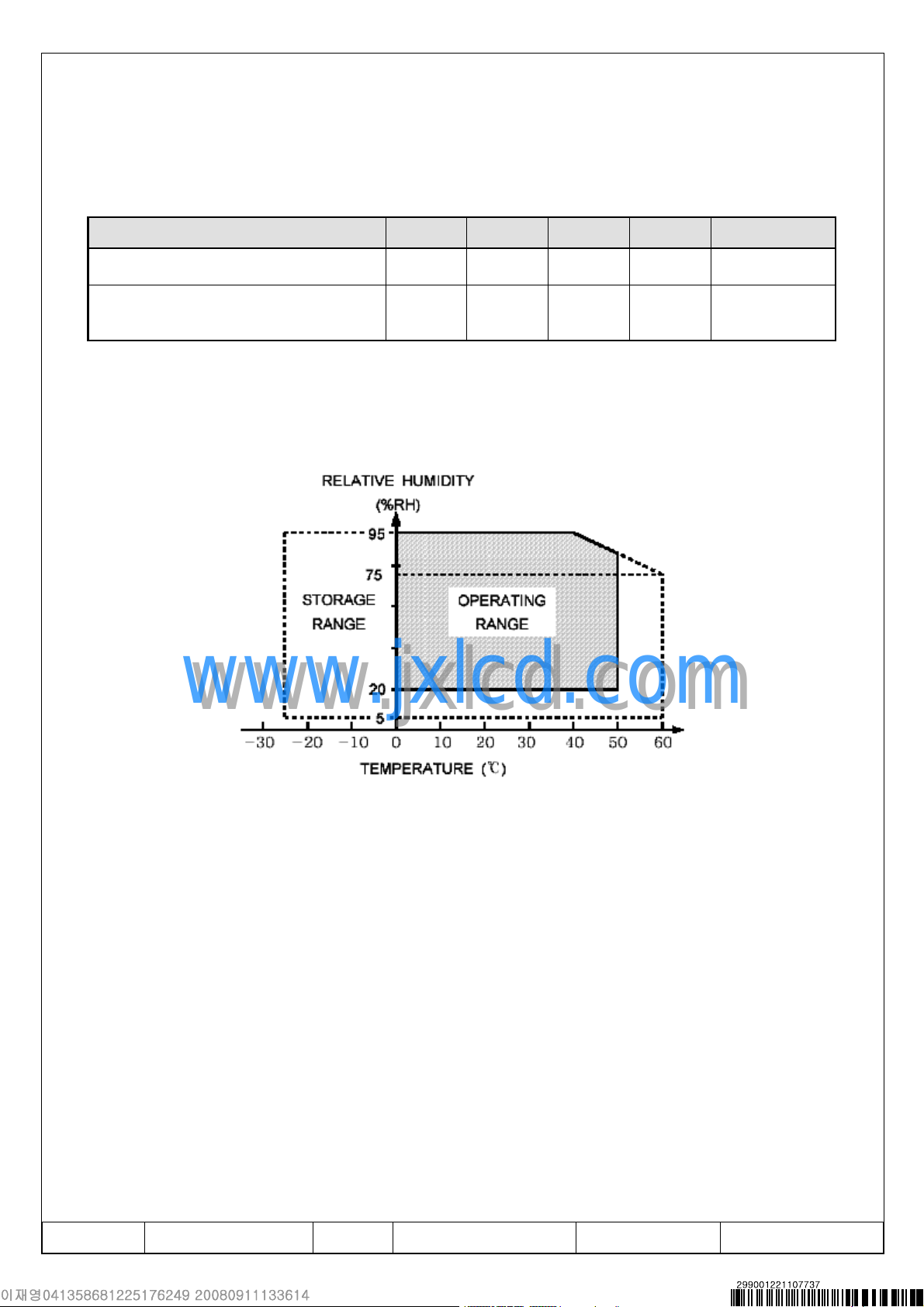
Storage temperature TSTG -20 60 ℃ (1)
Operating temperature
(Ambient temperature)
Note (1) 90% RH Max. ( 40 °C ≥ Ta )
Maximum wet-bulb temperature at 39 °C or less. (Ta > 40 °C) No condensation.
www.jxlcd.com
www.jxlcd.com
TOPR 0 50 ℃ (1),(2),(3)
< Temperature & Humidity Graph at Absolute Environment >
Note (2) When operated at a temperature lower than 0℃,
the LCD worked slowly and the screen appeared low-contrast images
due to the characteristics of LC (Liquid Crystal).
Note (3) If any fixed pattern is displayed on LCD for minutes,
image-sticking phenomenon may occur.
Doc . No LTN089NT01 Rev.No G008-080909 Page 5/27

1.2 Electrical Absolute Ratings
(1) TFT-LCD Module
(Ta = 25 ± 2°C)
Characteristics Symbol Min. Max. Unit Note
Logic / LCD Voltage VDD 2.7 3.6 V (1)
Note (1) If used beyond absolute maximum ratings, the LSI may permanently be damaged.
It is strongly recommended to use the LSI within the condition of electrical characteristics for normal operation. Exposure to a condition not within the electrical
characteristics may affect the reliability of device.
(2) Back-Light Unit
(Ta = 25 ± 2°C)
Characteristics Symbol Min. Max. Unit Note
LED Current I
Note (2) Permanent damage to the device may occur if maximum values are exceeded or
reverse voltage is loaded.
Functional operation should be restricted to the conditions described under normal
www.jxlcd.com
www.jxlcd.com
operating conditions.
L
- 30 mA (2)
Doc . No LTN089NT01 Rev.No G008-080909 Page 6/27

2. Optical Characteristics
The following items are measured under stable conditions. The optical characteristics should be measured
in a dark room or equivalent state with the methods shown in Note (1), (2), (3).
* Measuring equipment: SR-3, BM-7, EZ-Contrast
(Ta = 25±2°C, VDD = 3.3V)
Item Symbol Condition Min. Typ. Max. Unit Note
Contrast ratio C/R
Luminance of white YL
NTSC Color Saturation - B/L on 40 45 - % -
Response
time
Color
Chromaticity
(CIE 1931)
Viewing
angle
Rising:Tr
Falling:Tf
White
Red
Green
www.jxlcd.com
www.jxlcd.com
Blue
Hor.
Ver.
Tr+Tf
Wx (0.263) 0.313 (0.363)
Wy (0.279) 0.329 (0.379)
Rx (0.545) 0.595 (0.645)
Ry (0.295) 0.345 (0.395)
Gx (0.270) 0.320 (0.370)
Gy (0.505) 0.555 (0.605)
Bx (0.100) 0.150 (0.200)
By (0.095) 0.145 (0.195)
qL
qR 40 (50) -
fH 15 (25) -
fL 30 (40) -
B/L on
(aver. 5p)
IL=20mA
(aver. 5p)
Φ=0
θ=0
Normal
Viewing
Angle
B/L On
C/R≥10
B/L On
250 500 - -
170 200 - cd/m2
- 16 32 msec
-
40 (50) -
Degrees
Ez-Contrast
(4)
SR-3
(5)
SR-3
(6)
BM-7
(7)
SR-3
(8)
White uniformity B
uni
(13points) 62.5 80 - %
(9)
SR-3
Doc . No LTN089NT01 Rev.No G008-080909 Page 7/27

Note (1) The optical characteristics is measured with Back-light.
Note (2) If product is exposed to high temperatures for accelerated lift test or extended time,
there is a possibility of the W/V polarizer film damage which could degrade the
optical characteristics(Contrast ratio). But, Nothing is the matter in room temperature.
Note (3) Test Equipment Setup for the Transmissive Mode (Back-light On)
After stabilizing and leaving the panel alone at a given temperature for 30 sec,
the measurement should be executed. Measurement should be executed in a stable,
windless, and dark room. This should be measured in the center of screen.
- Back-light Current : IL=20 mA
- Back-Light On condition
Photo detector
Field
FieldPhoto detector
FieldPhoto detector
1°SR-3
www.jxlcd.com
www.jxlcd.com
TFT-LCD Module
Note (4) Definition of Contrast Ratio (C/R) : Ratio of gray max (Gmax) & gray min (Gmin)
of 5 points of the panel. ( 4, 5, 7, 9, 10 of Note(9) )
If Back-light is on state, it is the light source and the SR-3 will be used to measure.
1°SR-3
50cmSR-3
1°BM-7
1°BM-7
LCD panel
Center of the screen
50cmSR-3
50cmBM-7
50cmBM-7
DPhoto detector
DPhoto detector
C/R=
Gmax
Gmin
* Gmax : Luminance with all pixels white
* Gmin : Luminance with all pixels black
Doc . No LTN089NT01 Rev.No G008-080909 Page 8/27
Note (5) Definition of Luminance of White : (Average) Luminance of white at 5 points.
( 4, 5, 7, 9, 10 of Note(9) )
In this case, the incident light is not from the light source but from the Back-light
that generates the reflected light source on LCD in the dark room.
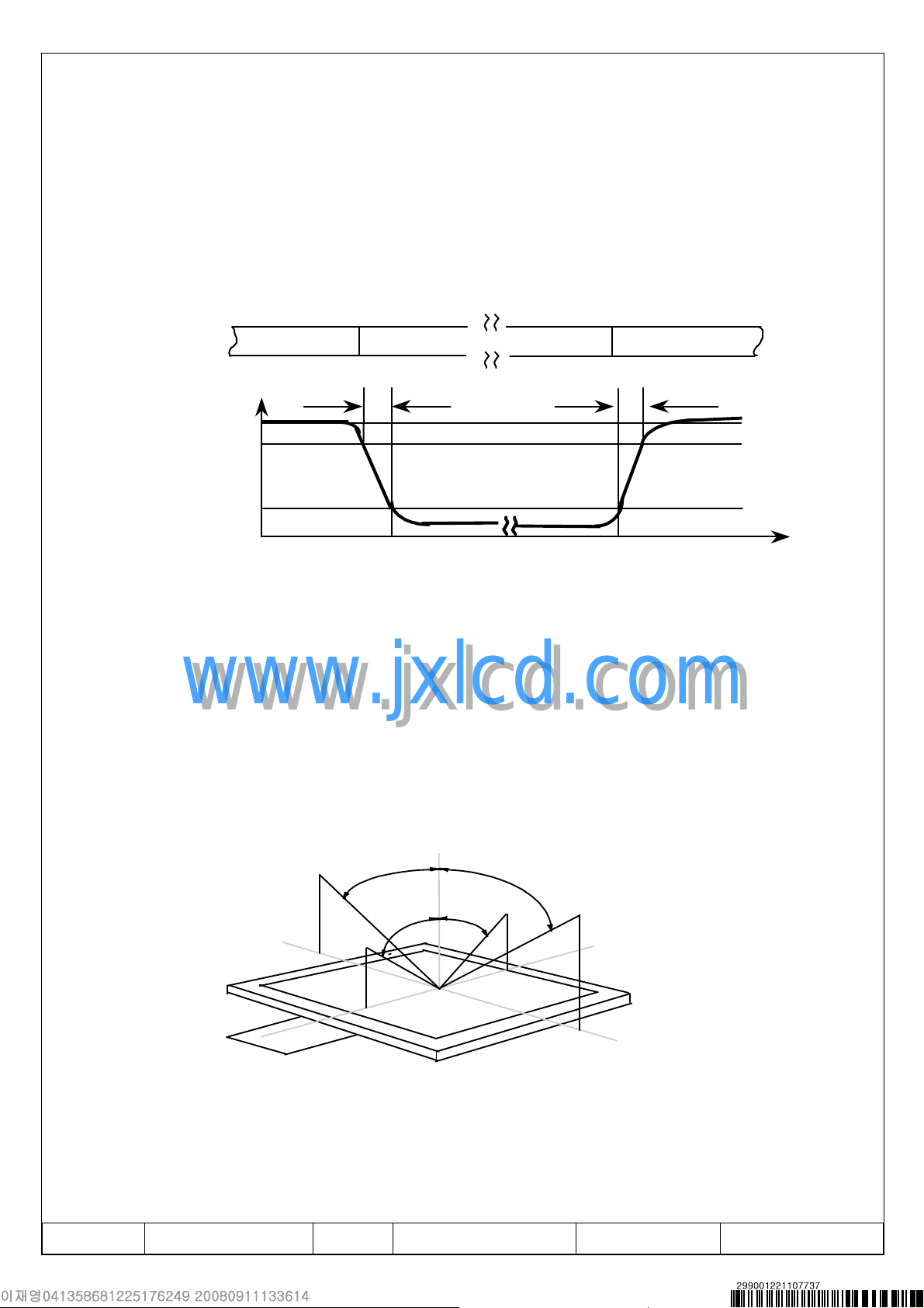
Note (6) Definition of Response time : Sum of Tr ,Tf
Display data
Optical
Response
Note (7) Definition of Color Chromaticity (CIE 1931), (Back-light: On)
It should be measured with standard light source or single rank of LED.
www.jxlcd.com
www.jxlcd.com
Note (8) Definition of Viewing Angle : Viewing angle range
White(TFT OFF) White(TFT OFF)
T
R
100%
90%
10%
0%
Black(TFT ON)
T
F
Time
Normal Line
o
,
θ = 0
o
θ
R
12 o’clock
direction
y
φ H = 90o
x'
o
θR =90
θ L =90
6 o’clock
direction
φ L= 90o
φ = 0
θ
L
φ
φ
o
x
L
H
y'
Doc . No LTN089NT01 Rev.No G008-080909 Page 9/27
 Loading...