

Page 1
Owner’s
Instructions
TFT-LCD TELEVISION
........................................................................................................................
.............
LTM225W
BN68-00349A-04
Samsung Electronics America Inc.
400 Valley Road, Suite 201, Mt. Arlington, NJ 07856
SERVICE DIVISION
TEL: 1-800-SAMSUNG (1-800-726-7864)
www.samsungusa.com
00.cover_en 12/5/02 10:14 AM Page 1
Page 2
Warning! Important
Safety Instructions
CAUTION: TO REDUCE THE RISK OFELECTRIC SHOCK, DO NOT
REMOVE COVER (OR BACK). NO USER SERVICEABLE PARTS INSIDE.
REFER SERVICING TO QUALIFIED SERVICE PERSONNEL.
This symbol indicates high voltage is present inside.
It is dangerous to make any kind of contact with any inside
part of this product.
This symbol alerts you that important literature concerning
operation and maintenance has been included with this product.
Note to CATV system installer: This reminder is provided to call CATV system
installer’s attention to Article 820-40 of the National Electrical Code (Section 54 of
Canadian Electrical Code, Part I), that provides guidelines for proper grounding and,
in particular, specifies that the cable ground shall be connected to the grounding
system of the building as close to the point of cable entry as practical.
Caution: FCC/CSA regulations state that any unauthorized changes or modifications
to this equipment may void the user’s authority to operate it.
Caution: To prevent electric shock, match the wide blade of plug to the wide slot, and
fully insert the plug.
Attention: pour eviter les chocs electriques, introduire la lame le plus large de la
fiche dans la borne correspondante de la prise et pousser jusqu’au fond.
Important: One Federal Court has held that unauthorized recording of
copyrighted TV programs is an infringement of U.S. copyright laws.
Certain Canadian programs may also be copyrighted and any unauthorized recording
in whole or in part may be in violation of these rights.
To prevent damage which may result in fire or electric shock
hazard, do not expose this appliance to rain or moisture.
CAUTION
RISK OF ELECTRIC SHOCK
DO NOT OPEN
01.INSIDE FRONT COVER_EN 2/4/03 11:44 PM Page 1
Page 3

SAFETY 1
Thank You for Choosing Samsung
Thank you for choosing Samsung! Your new Samsung TV represents the latest in television
technology. We designed it with easy-to-use on-screen menus and closed captioning
capabilities, making it one of the best products in its class. We are proud to offer you a product
that will provide convenient, dependable service and enjoyment for years to come.
Important Safety Information
Always be careful when using your TV receiver. To reduce the risk of fire, electrical shock,
and other injuries, keep these safety precautions in mind when installing, using, and
maintaining your machine.
• Read all safety and operating instructions before operating your TV.
• Keep the safety and operating instructions for future reference.
• Heed all warnings on the TV receiver and in the operating instructions.
• Follow all operating and use instructions.
• Unplug the TV receiver from the wall outlet before cleaning.
Use a damp cloth; do not use liquid or aerosol cleaners.
• Never add any attachments and/or equipment without approval of the manufacturer.
Such additions can increase the risk of fire, electric shock, or other personal injury.
• Do not use the TV receiver where contact with or immersion in water is a possibility,
such as near bath tubs, sinks, washing machines, swimming pools, etc.
• Do not place the TV on an unstable cart, stand, tripod, bracket, or
table where it can fall. Afalling TV can cause serious injury to a
child or adult, and serious damage to the appliance. Use only with
a cart, stand, tripod, bracket, or table recommended by the
manufacturer or sold with the TV. Follow the manufacturer’s
instructions when mounting the unit, and use a mounting
accessory recommended by the manufacturer. Move the TV and
cart with care. Quick stops, excessive force, and uneven surfaces
can make the unit and cart unsteady and likely to overturn.
• Provide ventilation for the TV receiver. The unit is designed with
slots in the cabinet for ventilation to protect it from overheating. Do not block these openings
with any object, and do not place the TV receiver on a bed, sofa, rug, or other similar surface.
Do not place it near a radiator or heat register. If you place the TV receiver on a rack or
bookcase, ensure that there is adequate ventilation and that you’ve followed the
manufacturer’s instructions for mounting.
• Operate your TV receiver only from the type of power source indicated on the marking label.
If you are not sure of the type of power supplied to your home, consult your appliance dealer
or local power company.
• Use only a grounded or polarized outlet. For your safety, this TV is equipped with a
polarized alternating current line plug having one blade wider than the other. This plug will
fit into the power outlet only one way. If you are unable to insert the plug fully into the
outlet, try reversing the plug. If the plug still does not fit, contact your electrician to replace
your outlet.
02.PREFACE_EN 2/4/03 11:44 PM Page 1
Page 4
• Protect the power cord. Power supply cords should be routed so that they won’t be walked on
or pinched by objects placed on or against them. Pay particular attention to cords at plugs,
convenience receptacles, and the point where they exit from the unit.
• Unplug the TV from the wall outlet and disconnect the antenna or cable system during a
lightning storm or when left unattended and unused for long periods of time.
This will prevent damage to the unit due to lightning and power-line surges.
• Avoid overhead power lines. An outside antenna system should not be placed in the vicinity
of overhead power lines or other electric light or power circuits or where it can fall into such
power lines or circuits. When installing an outside antenna system, be extremely careful to
keep from touching the power lines or circuits. Contact with such lines can be fatal.
• Do not overload the wall outlet or extension cords.
Overloading can result in fire or electric shock.
• Do not insert anything through the openings in the unit, where they can touch dangerous
voltage points or damage parts. Never spill liquid of any kind on the TV.
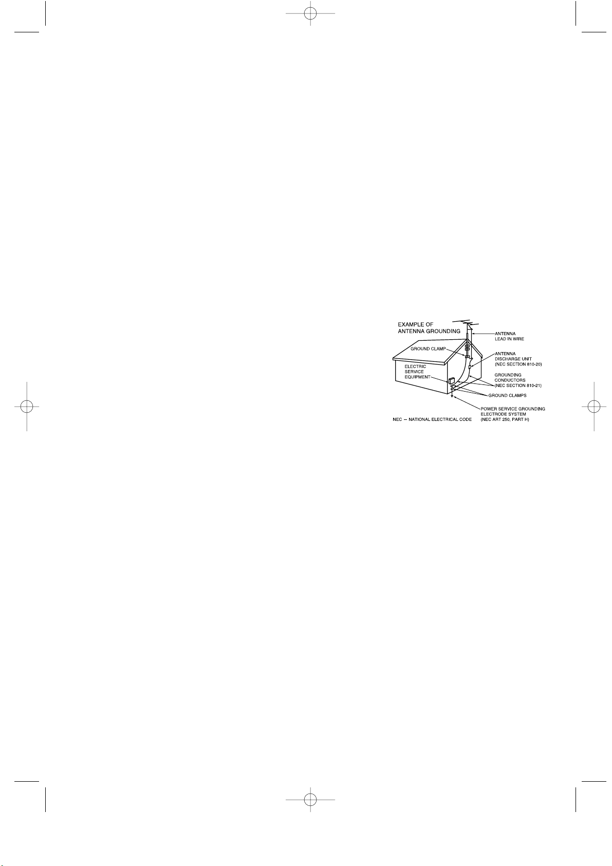
• Ground outdoor antennas. If an outside antenna or
cable system is connected to the TV, be sure the
antenna or cable system is grounded so as to provide
some protection against voltage surges and built-up
static charges. Section 810 of the National Electrical
Code, ANSI/NFPA No.70-1984, provides information
about proper grounding of the mast and supporting
structure, grounding of the lead-in wire to an antenna
discharge unit, size of grounding conductors, location
of antenna discharge unit, connection to grounding
electrodes, and requirements for the grounding
electrode.
• Do not attempt to service the TV yourself. Refer all servicing to qualified service personnel.
Unplug the unit from the wall outlet and refer servicing to qualified service personnel under
the following conditions:
- when the power-supply cord or plug is damaged
- if liquid has been spilled on the unit or if objects have fallen into the unit
- if the TV has been exposed to rain or water
- if the TV does not operate normally by following the operating instructions
- if the TV has been dropped or the cabinet has been damaged
- when the TV exhibits a distinct change in performance
• If you make adjustments yourself, adjust only those controls that are covered by the
operating instructions. Adjusting other controls may result in damage and will often require
extensive work by a qualified technician to restore the TV to normal.
• When replacement parts are required, be sure the service technician uses replacement parts
specified by the manufacturer or those that have the same characteristics as the original part.
Unauthorized substitutions may result in additional damage to the unit.
• Upon completion of any service or repairs to this TV, ask the service technician to
perform safety checks to determine that the TV is in a safe operating condition.
2 SAFETY
02.PREFACE_EN 2/4/03 11:44 PM Page 2
Page 5

SAFETY 3
• Keep all power adapters apart.
->Possible fire hazard.
• Keep power adapter away from any other heat source.
->Possible fire hazard.
• Remove and discard vinyl bag from power adapter before use.
->Possible fire hazard.
• Always keep power adapters in well-ventilated area.
02.PREFACE_EN 2/4/03 11:44 PM Page 3
Page 6

Information to the user
NOTE: This equipment has been tested
and found to comply with the limits for a
Class B digital device, pursuant to Part 15
of the FCC Rules. These limits are
designed to provide reasonable protection
against harmful interference in a
residential installation. This equipment
generates, uses and can radiate radio
frequency energy and, if not installed and
used in accordance with the instructions,
may cause harmful interference to radio
communications. However, there is no
guarantee that interference will not occur
in a particular installation. If this equipment
does cause harmful interference to radio or
television reception, which can be determined by turning the equipment off and on,
the user is encouraged to try to correct the
interference by one or more of the following measures:
-- Reorient or relocate the receiving
antenna.
-- Increase the separation between the
equipment and receiver.
-- Connect the equipment into an outlet
on a different from that to which the
receiver is connected.
-- Consult the dealer or an experienced
radio/TV technician for help.
Changes or modifications not expressly
approved by the party responsible for
compliance could void the user’s authority
to operate the equipment.
Warning
User must use shielded signal interface
cables to maintain FCC compliance for the
product.
The party responsible for product
compliance:
SAMSUNG ELECTRONICS CO., LTD
America QA Lab of Samsung
85 West Tasman Drive
Irvine, CA 95134 USA
Provided with this monitor is a detachable
power supply cord with IEC320 style
terminations. It may be suitable for
connection to any UL Listed personal
computer with similar configuration. Before
making the connection, make sure the voltage rating of the computer convenience
outlet is the same as the monitor and that
the ampere rating of the computer convenience outlet is equal to or exceeds the
monitor voltage rating.
For 120 Volt applications, use only UL
Listed detachable power cord with NEMA
configuration 5-15P type (parallel blades)
plug cap. For 240 Volt applications use
only UL Listed Detachable power supply
cord with NEMA configuration 6015P type
(tandem blades) plug cap.
IC Compliance Notice
This Class B digital apparatus meets all
requirements of the Canadian
Interference-Causing Equipment
Regulations of ICES-003.
Notice de Conformité IC
Cet appareil numérique de classe B
respecte toutes les exigences du
Règlement ICES-003 sur les équipements
produisant des interférences au Canada.
VCCI
This is a Class B product based on the
standard of the Voluntary Control Council
for Interference by Informatinon
Technology Equipment (VCCI). If this is
used near a radio or television receiver in
a domestic environment, it may cause
radio interference. Install and use the
equipment according to the instruction
manual.
FCC Information
4 SAFETY
03.FCC INFORMATION_EN 2/4/03 11:45 PM Page 1
Page 7

CONTENTS 1
CONTENTS
Chapter 1: Your New TV . . . . . . . . . . . . . . .1.1
List of Features . . . . . . . . . . . . . . . . . . . . . . . . . . . . . . . . . . . . . . . . . . .1.1
List of Parts . . . . . . . . . . . . . . . . . . . . . . . . . . . . . . . . . . . . . . . . . . . . . .1.1
Familiarizing Yourself with Your New TV . . . . . . . . . . . . . . . . . . . . . .1.2
Front Panel Buttons . . . . . . . . . . . . . . . . . . . . . . . . . . . . . . . .1.2
Rear Panel Jacks . . . . . . . . . . . . . . . . . . . . . . . . . . . . . . . . . .1.3
Remote Control . . . . . . . . . . . . . . . . . . . . . . . . . . . . . . . . . . .1.4
Chapter 2: Installation . . . . . . . . . . . . . . . . 2.1
Connecting VHF and UHF Antennas . . . . . . . . . . . . . . . . . . . . . . . . . .2.1
Antennas with 300-ohm Flat Twin Leads . . . . . . . . . . . . . . .2.1
Antennas with 75-ohm Round Leads . . . . . . . . . . . . . . . . . .2.2
Separate VHF and UHF Antennas . . . . . . . . . . . . . . . . . . . . .2.2
Connecting Cable TV . . . . . . . . . . . . . . . . . . . . . . . . . . . . . . . . . . . . . .2.2
Cable without a Cable Box . . . . . . . . . . . . . . . . . . . . . . . . . .2.2
Connecting to a Cable Box that Descrambles All Channels .2.3
Connecting to a Cable Box that
Descrambles Some Channels . . . . . . . . . . . . . . . . . . . . . . . . .2.3
Connecting a VCR . . . . . . . . . . . . . . . . . . . . . . . . . . . . . . . . . . . . . . . .2.5
Connecting an S-VHS VCR . . . . . . . . . . . . . . . . . . . . . . . . .2.6
Connecting a DVD Player . . . . . . . . . . . . . . . . . . . . . . . . . . . . . . . . . .2.7
Connecting a Digital TV Set-Top Box . . . . . . . . . . . . . . . . . . . . . . . . .2.7
Connecting a PC . . . . . . . . . . . . . . . . . . . . . . . . . . . . . . . . . . . . . . . . . .2.8
Connecting to a Sub-woofer . . . . . . . . . . . . . . . . . . . . . . . . . . . . . . . .2.9
Installing Batteries in the Remote Control . . . . . . . . . . . . . . . . . . . . . .2.9
Chapter 3: Operation . . . . . . . . . . . . . . . . . .3.1
Turning the TVOn and Off . . . . . . . . . . . . . . . . . . . . . . . . . . . . . . . . .3.1
Plug & Play Feature . . . . . . . . . . . . . . . . . . . . . . . . . . . . . . . . . . . . . . .3.1
Viewing the Menus and On-Screen Displays . . . . . . . . . . . . . . . . . . . .3.3
Viewing the Menus . . . . . . . . . . . . . . . . . . . . . . . . . . . . . . . .3.3
Viewing the Display . . . . . . . . . . . . . . . . . . . . . . . . . . . . . . .3.3
Selecting a Menu Language . . . . . . . . . . . . . . . . . . . . . . . . . . . . . . . . .3.4
Memorizing the Channels . . . . . . . . . . . . . . . . . . . . . . . . . . . . . . . . . . .3.5
Selecting the Video Signal-source . . . . . . . . . . . . . . . . . . . . .3.5
Storing Channels in Memory (Automatic Method) . . . . . . . .3.6
Adding and Erasing Channels (Manual Method) . . . . . . . . .3.7
Changing Channels . . . . . . . . . . . . . . . . . . . . . . . . . . . . . . . . . . . . . . . .3.7
Using the Channel Buttons . . . . . . . . . . . . . . . . . . . . . . . . . .3.7
Directly Accessing Channels . . . . . . . . . . . . . . . . . . . . . . . . .3.7
Using the Pre-CH Button to select the Previous Channel . . .3.7
Adjusting the Volume . . . . . . . . . . . . . . . . . . . . . . . . . . . . . . . . . . . . . .3.8
Using Mute . . . . . . . . . . . . . . . . . . . . . . . . . . . . . . . . . . . . . .3.8
Setting the Clock . . . . . . . . . . . . . . . . . . . . . . . . . . . . . . . . . . . . . . . . .3.9
Customizing the Picture . . . . . . . . . . . . . . . . . . . . . . . . . . . . . . . . . . .3.10
Using Automatic Picture Settings . . . . . . . . . . . . . . . . . . . . . . . . . . . .3.11
Customizing the Sound . . . . . . . . . . . . . . . . . . . . . . . . . . . . . . . . . . . .3.12
Using Automatic Sound Settings . . . . . . . . . . . . . . . . . . . . . . . . . . . .3.13
Viewing a VCR or Camcorder Tape . . . . . . . . . . . . . . . . . . . . . . . . . .3.14
04.CONTENTS_EN 4/24/03 9:22 PM Page 1
Page 8

2 CONTENTS
CONTENTS
Chapter 4: Special Features . . . . . . . . . . . .4.1
Setting Up Your Remote Control . . . . . . . . . . . . . . . . . . . . . . . . . . . . .4.1
Fine Tuning Channels . . . . . . . . . . . . . . . . . . . . . . . . . . . . . . . . . . . . . .4.5
LNA (Low Noise Amplifier) . . . . . . . . . . . . . . . . . . . . . . . . . . . . . . . .4.6
Setting the Blue Screen Mode . . . . . . . . . . . . . . . . . . . . . . . . . . . . . . .4.7
Changing the Screen Size . . . . . . . . . . . . . . . . . . . . . . . . . . . . . . . . . . .4.8
Freezing the Picture . . . . . . . . . . . . . . . . . . . . . . . . . . . . . . . . . . . . . . .4.8
Special Sound Options . . . . . . . . . . . . . . . . . . . . . . . . . . . . . . . . . . . . .4.9
Choosing a Multi-Channel Sound (MTS) Soundtrack . . . . .4.9
Auto Volume . . . . . . . . . . . . . . . . . . . . . . . . . . . . . . . . . . . .4.10
Virtual Dolby . . . . . . . . . . . . . . . . . . . . . . . . . . . . . . . . . . . .4.11
Adjusting the Headphone Sound . . . . . . . . . . . . . . . . . . . . .4.12
Selecting the Sound . . . . . . . . . . . . . . . . . . . . . . . . . . . . . . .4.13
Setting the On/Off Timer . . . . . . . . . . . . . . . . . . . . . . . . . . . . . . . . . .4.14
Viewing Closed Captions . . . . . . . . . . . . . . . . . . . . . . . . . . . . . . . . . .4.16
Viewing Picture-in-Picture . . . . . . . . . . . . . . . . . . . . . . . . . . . . . . . . .4.17
Activating Picture-in-Picture . . . . . . . . . . . . . . . . . . . . . . . .4.17
Selecting a Signal Source (External A/V) for PIP . . . . . . . .4.18
Swapping the Contents of the PIP and Main image . . . . . .4.18
Changing the PIP Channel . . . . . . . . . . . . . . . . . . . . . . . . . .4.18
Changing the Location of the PIP Window . . . . . . . . . . . . .4.18
Changing the Size of the PIP Window . . . . . . . . . . . . . . . . .4.18
Using the V-Chip . . . . . . . . . . . . . . . . . . . . . . . . . . . . . . . . . . . . . . . .4.19
Setting Up Your Personal ID Number (PIN) . . . . . . . . . . . .4.19
How to Enable/Disable the V-Chip . . . . . . . . . . . . . . . . . . .4.20
How to Set up Restrictions Using the “TV guidelines” . . . .4.20
How to Set up Restrictions using the MPAA Ratings:
G, PG, PG-13, R, NC-17, X . . . . . . . . . . . . . . . . . . . . . . . .4.22
How to Reset the TV after the V-Chip
Blocks a Channel (“Emergency Escape”) . . . . . . . . . . . . . .4.23
Chapter 5: PC Display . . . . . . . . . . . . . . . . .5.1
Using Your TV as a Computer (PC) Display . . . . . . . . . . . . . . . . . . . .5.1
How to Set up Your PC Software (Windows only) . . . . . . . .5.1
Adjusting the Screen Quality . . . . . . . . . . . . . . . . . . . . . . . . .5.2
Changing the Screen Position . . . . . . . . . . . . . . . . . . . . . . . .5.3
Changing the Screen Color Standard . . . . . . . . . . . . . . . . . . .5.4
Adjusting the Screen Color Settings . . . . . . . . . . . . . . . . . . .5.5
Chapter 6: Troubleshooting . . . . . . . . . . . .6.1
Identifying Problems . . . . . . . . . . . . . . . . . . . . . . . . . . . . . . . . . . . . . .6.1
Appendix . . . . . . . . . . . . . . . . . . . . . . . . . . .A.1
Display Modes . . . . . . . . . . . . . . . . . . . . . . . . . . . . . . . . . . . . . . . . . . .A.1
Installing VESAcompliant mounting devices . . . . . . . . . . . . . . . . . . .A.2
Attaching a Wall or Arm mounting device . . . . . . . . . . . . . . . . . . . . .A.3
Using the Anti-Theft Kensington Lock . . . . . . . . . . . . . . . . . . . . . . . .A.4
Pin Assignments . . . . . . . . . . . . . . . . . . . . . . . . . . . . . . . . . . . . . . . . .A.5
Cleaning and Maintaining Your TV . . . . . . . . . . . . . . . . . . . . . . . . . . .A.5
Using Your TV in Another Country . . . . . . . . . . . . . . . . . . . . . . . . . . .A.5
Specifications . . . . . . . . . . . . . . . . . . . . . . . . . . . . . . . . . . . . . . . . . . . .A.6
04.CONTENTS_EN 4/24/03 9:22 PM Page 2
Page 9
CHAPTER ONE: YOUR NEW TV 1.1
List of Features
Your TV was designed with the latest technology. This TV is a high-performance unit
that includes the following special features:
• Easy-to-use remote control
• Easy-to-use on-screen menu system
• Automatic timer to turn the TV on and off
• Adjustable picture and sound settings that can be stored in the TV’s memory
• Automatic channel tuning for up to 181 channels
• Aspecial filter to reduce or eliminate reception problems
• Fine tuning control for the sharpest picture possible
• Abuilt-in multi-channel sound decoder for stereo and bilingual listening
• Built-in, dual channel speakers
• Headphone jack for private listening
• 16:9 letter box format available depending upon source
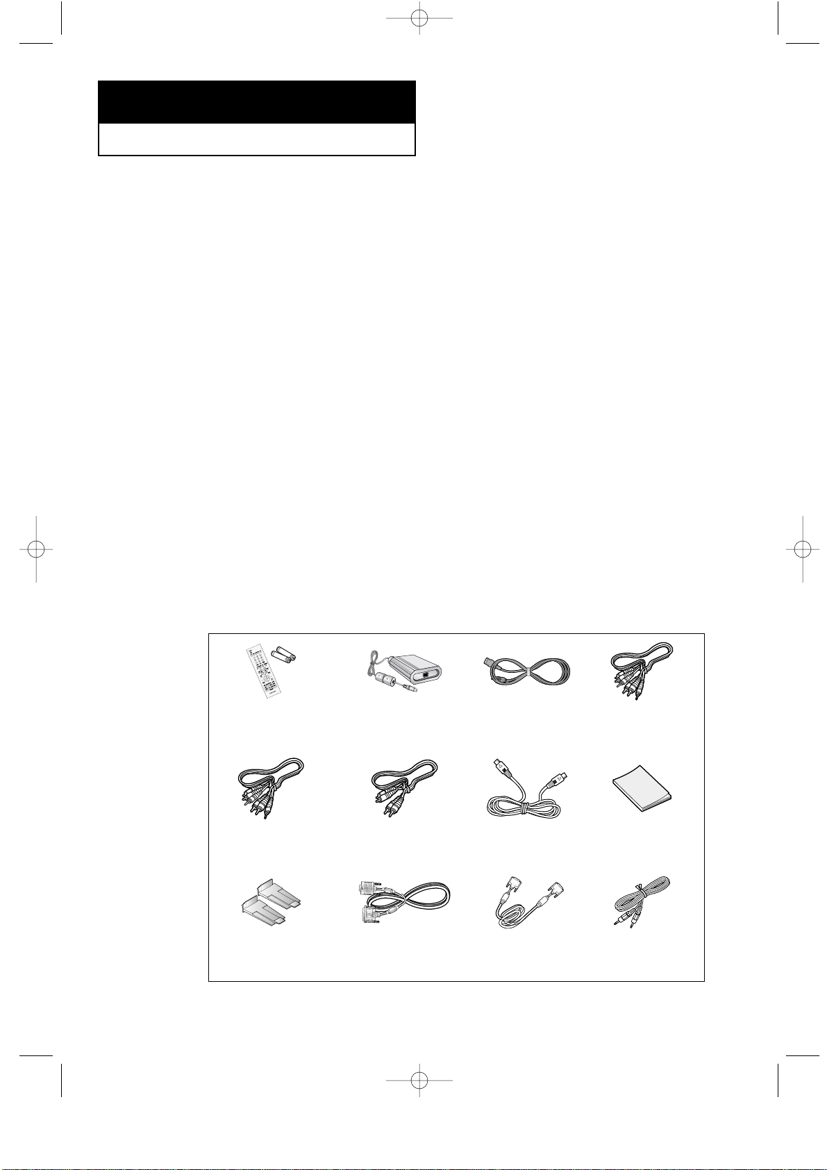
List of Parts
Please make sure the following items are included with your LCD TV. If any items are
missing, contact your dealer.
Chapter One
YOUR NEW TV
Remote Control
(BN59-00306B) &
Batteries (AA x 2)
Adapter
(BN44-00051C)
POWER CORD
(BH39-10339X)
S-VIDEO CABLE
(BN39-00060A)
COMPONENT AUDIO
CABLE
(BN39-00148A)
COMPONENT CABLE
(BN39-00279A)
SIGNAL-RCA/
VIDEO CABLE
(BN39-00057A)
Owner’s
Instructions
PC VIDEO CABLE
(DVI-D+DVI-D)
(BN39-00072A)
STAND CAP
(BN96-00287C)
PC VIDEO CABLE
(DVI+D-SUB)
(BN39-00310A)
PC AUDIO CABLE
(BH39-00120A)
05.CHAPTER1_EN 2/18/03 3:33 AM Page 1
Page 10
1.2 CHAPTER ONE: YOUR NEW TV
Familiarizing Yourself with The TV
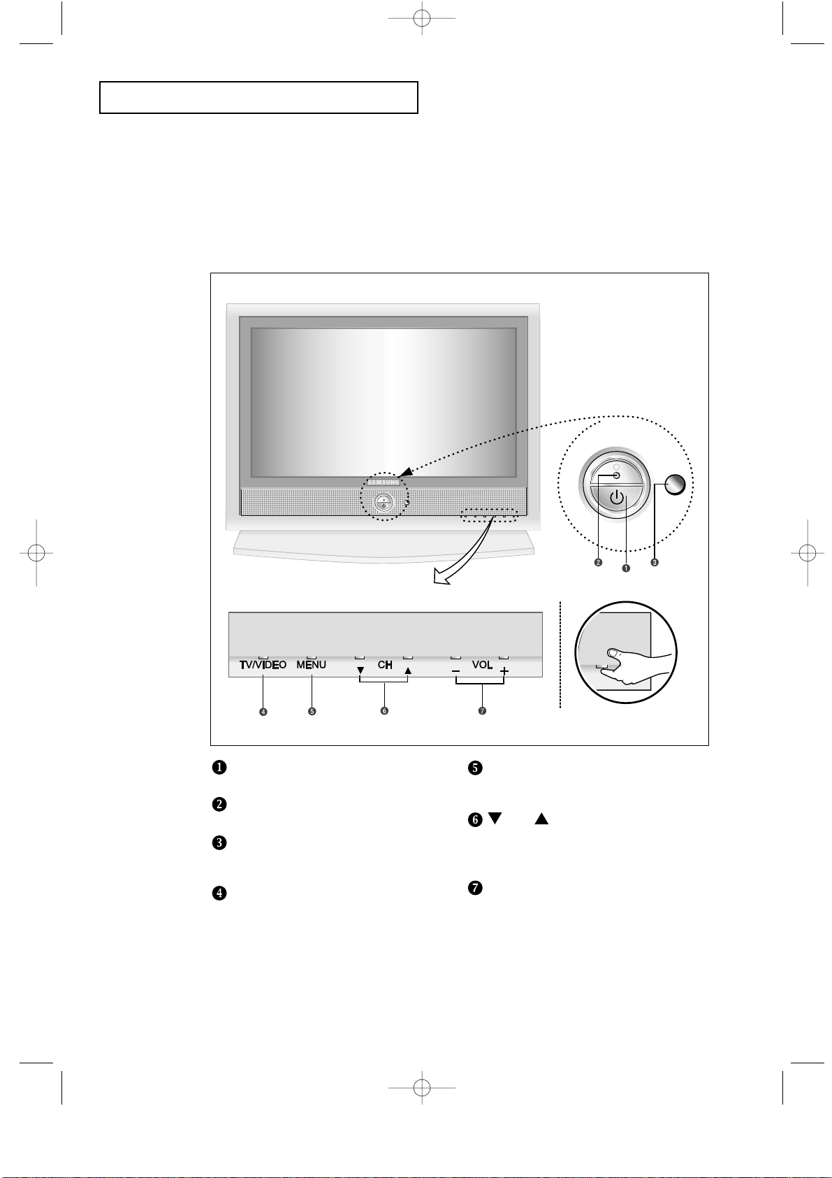
Front Panel Buttons
The buttons on the front panel control your TV’s basic features, including the on-screen
menu. To use the more advanced features, you must use the remote control.
YOUR NEW TV
Power
Press to turn the TV on and off.
Power Indicator
Lights up when you turn the power off.
Remote Control Sensor
Aim the remote control towards this spot
on the TV.
TV/VIDEO
Displays a menu of all of the available
input sources (TV, VIDEO, S-VIDEO,
Component 1, Component 2, PC/DVI).
MENU
Press to see an on-screen menu of
your TV’s features.
CH
Press to change channels.
Also press to highlight various items
on the on-screen menu.
– VOL +
Press to increase or decrease the volume.
Also used to select items on the
on-screen menu.
05.CHAPTER1_EN 2/4/03 11:46 PM Page 2
Page 11
CHAPTER ONE: YOUR NEW TV 1.3
YOUR NEW TV
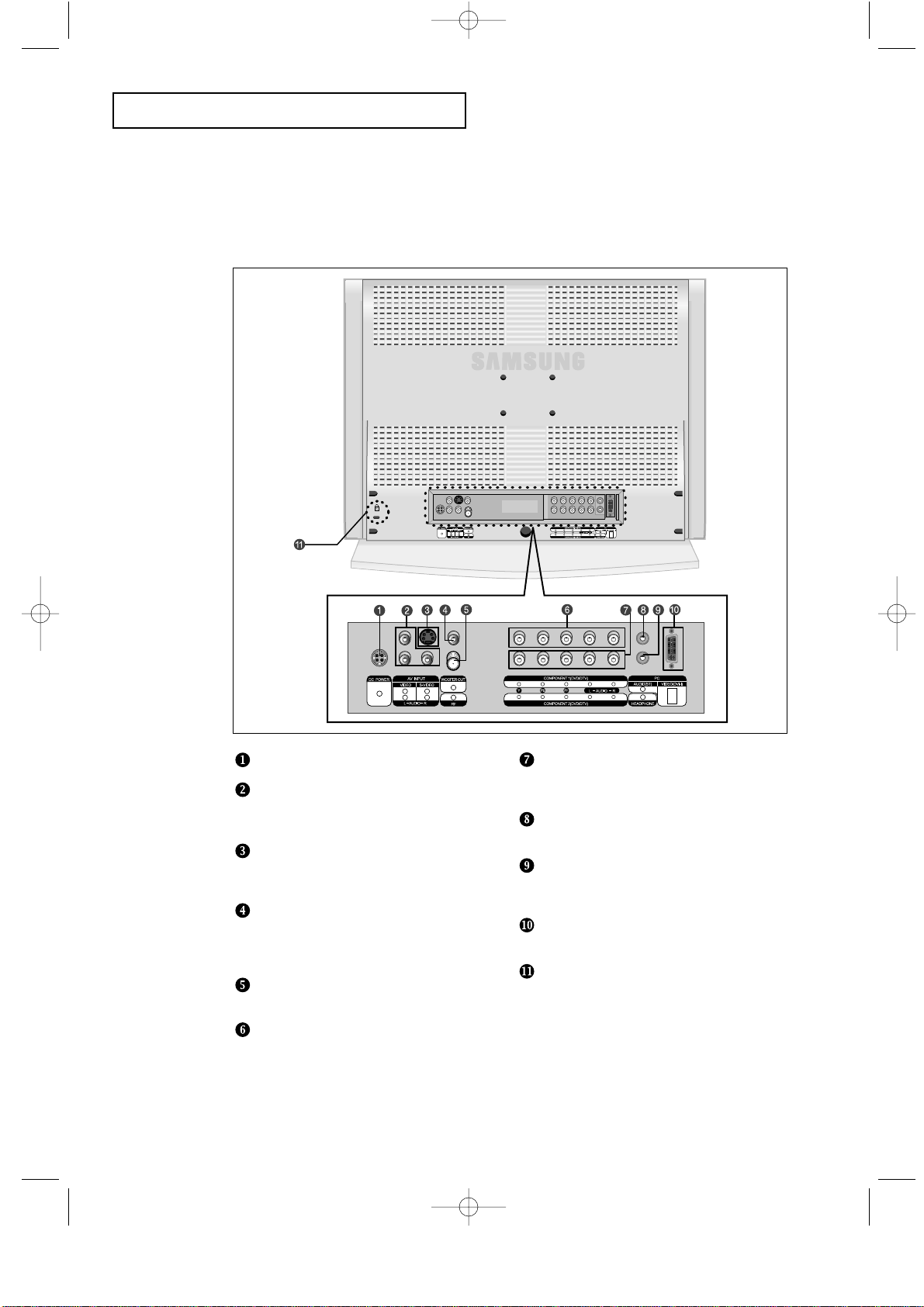
Rear Panel Jacks
Use the rear panel jacks to connect an A/Vcomponent that will be connected
continuously, such as a VCR or a DVD player.
For more information on connecting equipment, see pages 2.1 – 2.9.
DC POWER INPUT
VIDEO/AUDIO IN jack
Used to connect a video/audio signal from a
camcorder or a video game.
SUPER VIDEO IN jack
Used to connect an S-Video signal from a
camcorder or a video game.
WOOFER OUTPUT
Connect RCA audio cable system or external
amplifier.
(Option : Active Woofer 500mV RMS at 20-150Hz)
TV ANTENNA
Connects to an antenna or to a cable TV system.
COMPONENT 1(DVD/DTV)
Connects component video/audio from a
DVD player.
COMPONENT 2 (DVD/DTV)
Connects component video/audio from a
Set-Top Box.
PC AUDIO INPUT
Connect these to the audio-output jacks on your PC.
HEADPHONE jack
Connect a set of external headphones to this jack
for private listening.
PC VIDEO(DVI-I) INPUT
Connect to the video output port on your PC.
Kensington lock
(See page A.4)
05.CHAPTER1_EN 2/4/03 11:46 PM Page 3
Page 12
1.4 CHAPTER ONE: YOUR NEW TV
YOUR NEW TV
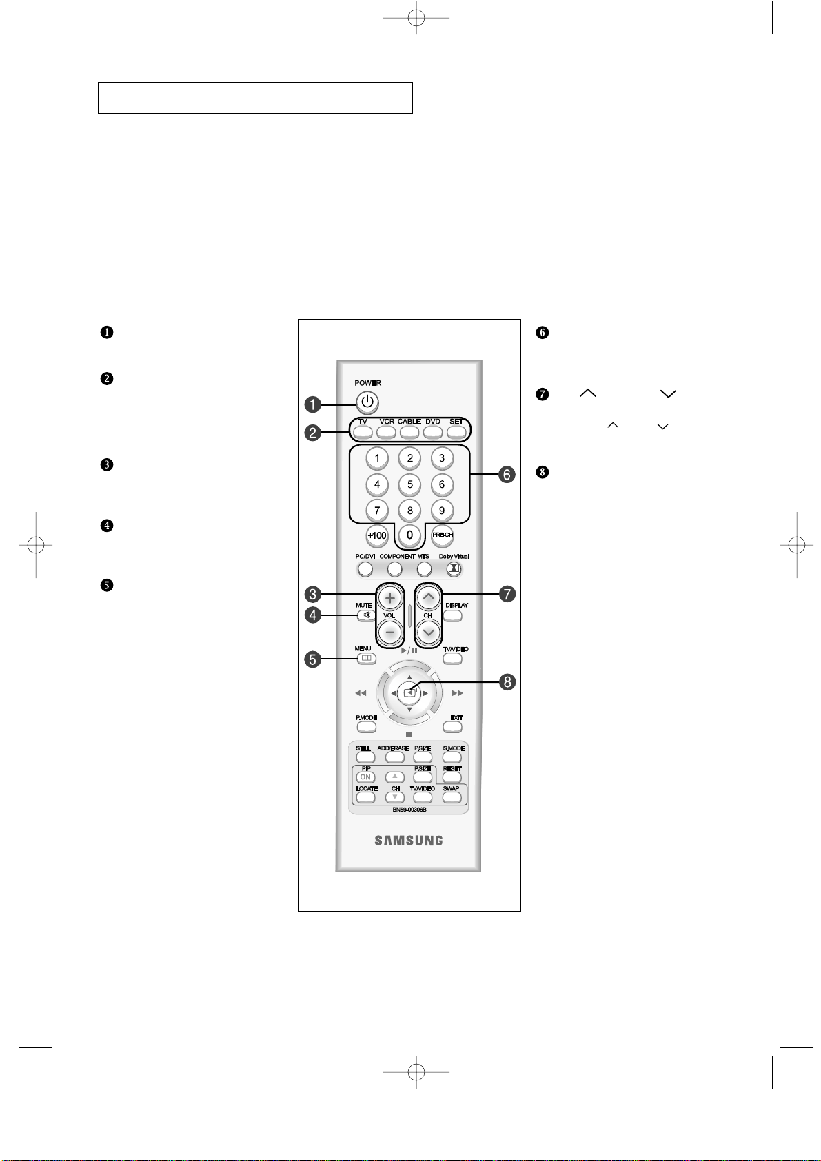
Remote Control
Frequently Used Buttons
Number buttons
Press to select channels directly
on the TV.
CH and CH
(Channel Up/Down)
Press CH or CH to change
channels.
JOYSTICK
Use to select on-screen menu
items and change menu values.
(The remote control will only
function with VCR or DVD units
that are compatible with the LCD TV.)
POWER
Turns the TV on and off.
MODE
Selects a target device to
controlled by the Samsung
remote control
(TV, VCR, Cable box or DVD).
VOL +, VOL -
Press to increase or decrease
the volume.
MUTE
Press to temporarily cut off
the sound.
MENU
Displays the main on-screen menu.
You can use the remote control up to a distance of about 23 feet from the TV. When using the remote,
always point it directly at the TV.
05.CHAPTER1_EN 2/4/03 11:46 PM Page 4
Page 13
CHAPTER ONE: YOUR NEW TV 1.5
YOUR NEW TV
Convenient Buttons
You can use the remote control up to 23 feet from the TV. When using the remote, always point it directly at the TV.
PRE-CH
Tunes to the previous channel.
MTS
(Multichannel Television Stereo)
Press to choose stereo, mono or
Separate Audio Program
(SAP broadcast).
Dolby Virtual
This feature allows the TV L/R
speakers to provide a Home
Theater-like Dolby effect.
DISPLAY
Press to display the current
channel and audio-video settings.
TV/VIDEO
Press to display all of the available
video sources.
EXIT
Press the menu to exit.
P.SIZE
Press to change the screen size.
S.MODE
Adjust the TV sound by selecting
one of the preset factory settings
(or select your personal, customized
sound settings).
RESET
Return to a previous menu on a
disc/teletext store. (If the remote
does not appear to function
correctly, remove the batteries and
press the ‘RESET’ key. Factory
settings are restored when the
batteries are replaced. Reset may
be used when other products
(DVD, VCR, etc.) are not working.)
+100
Press to select channels over 100.
For example, to select channel 121,
press “+100”, then press “2” and “1”.
COMPONENT
Press to switch to the
COMPONENT mode.
PC/DVI
Press to switch to the PC mode.
Menu adjustment and
Video or DVD
adjustment button
Moves or adjusts Menu.
Adjusts the function of Video or DVD.
P.MODE
Adjusts the TV picture by selecting
one of the preset factory settings.
ADD/ERASE
Press to add or erase channels
in the TV’s memory.
STILL
Press to stop the action during
a particular scene. Press again to
resume normal video.
PIP controls
CH
Displays the available channels
in sequence.
(These buttons change channels
in the PIP window only.)
P.SIZE
Press to make the PIP window
double, large or small.
LOCATE
Press to move the PIP window to
any of the four corners of the
TV screen.
TV/VIDEO
Press to select one of the available
signal sources for the PIP window.
SWAP
Exchanges the video signal that is
currently displayed on the main
screen with the signal in the PIP
window.
(While the main screen is in
PC mode, it does not work.)
05.CHAPTER1_EN 2/4/03 11:46 PM Page 5
Page 14
2.1 CHAPTER TWO: INSTALLATION
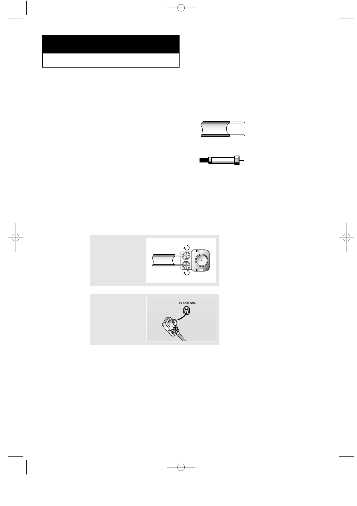
Connecting VHF and UHF Antennas
If your antenna has a set of leads that
look like this, see “Antennas with
300-ohm Flat Twin Leads”, below.
If your antenna has one lead that looks
like this, see “Antennas with 75-ohm
Round Leads”, on page 2.2.
If you have two antennas, see “Separate
VHF and UHF Antennas”, on page 2.2.
Antennas with 300-ohm Flat Twin Leads
If you are using an off-air antenna (such as a roof antenna or “rabbit ears”) that has
300-ohm twin flat leads, follow the directions below.
Chapter Two
INSTALLATION
1
Place the wires from
the twin leads under
the screws on a 30075 ohm adaptor (not
supplied). Use a
screwdriver to tighten
the screws.
2
Plug the adaptor into
the TV ANTENNA
terminal on the
bottom of the back
panel.
2
06.CHAPTER2_EN 2/5/03 12:34 AM Page 1
Page 15
CHAPTER TWO: INSTALLATION 2.2
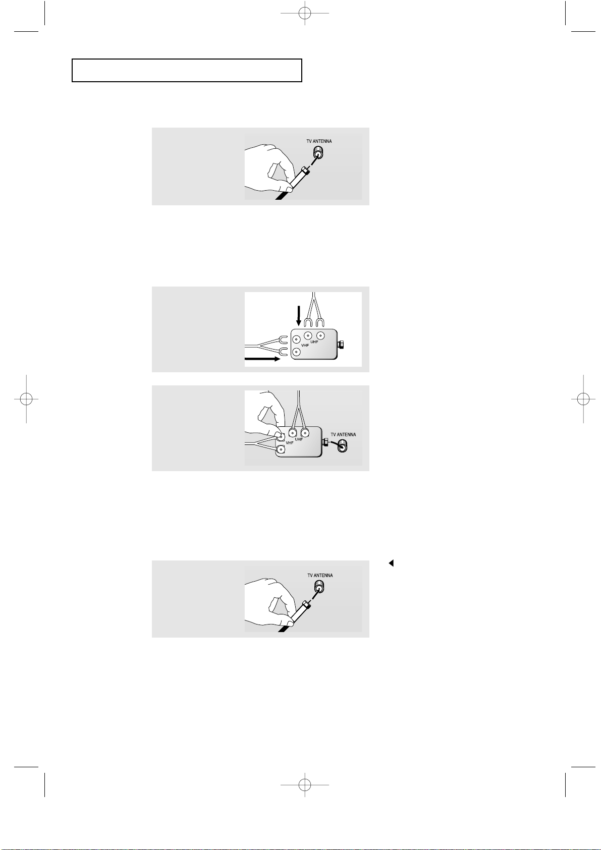
Connecting Cable TV
To connect to a cable TV system, follow the instructions below.
Cable without a Cable Box
1
Plug the incoming
cable into the TV
ANTENNA terminal
on back of the TV.
Because this TV is cable-ready,
you do not need a cable box to
view unscrambled cable channels.
2
Plug the combiner
into the TV
ANTENNA terminal
on the bottom of
the rear panel.
INSTALLATION
Antennas with 75-ohm Round Leads
1
Plug the antenna
lead into the TV
ANTENNA terminal
on the bottom of the
back panel.
Separate VHF and UHF Antennas
If you have two separate antennas for your TV (one VHF and one UHF), you must
combine the two antenna signals before connecting the antennas to the TV. This
procedure requires a an optional combiner-adaptor (available at most electronics shops).
1
Connect both antenna
leads to the combiner.
06.CHAPTER2_EN 2/5/03 12:34 AM Page 2
Page 16
2.3 CHAPTER TWO: INSTALLATION
INSTALLATION
Connecting to a Cable Box that Descrambles All Channels
1
Find the cable that is
connected to the
ANTENNA OUT
terminal on your cable
box.
This terminal might be labeled
“ANT OUT”, “VHF OUT”, or
simply, “OUT”.
2
Connect the other end
of this cable to the TV
ANTENNA terminal on
the back of the TV.
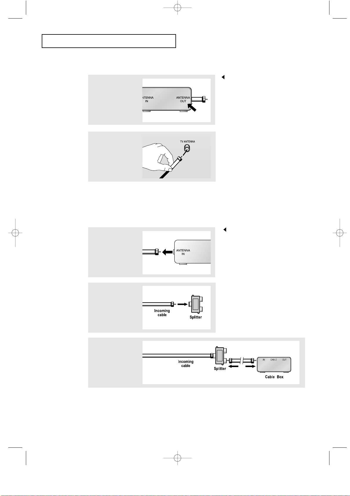
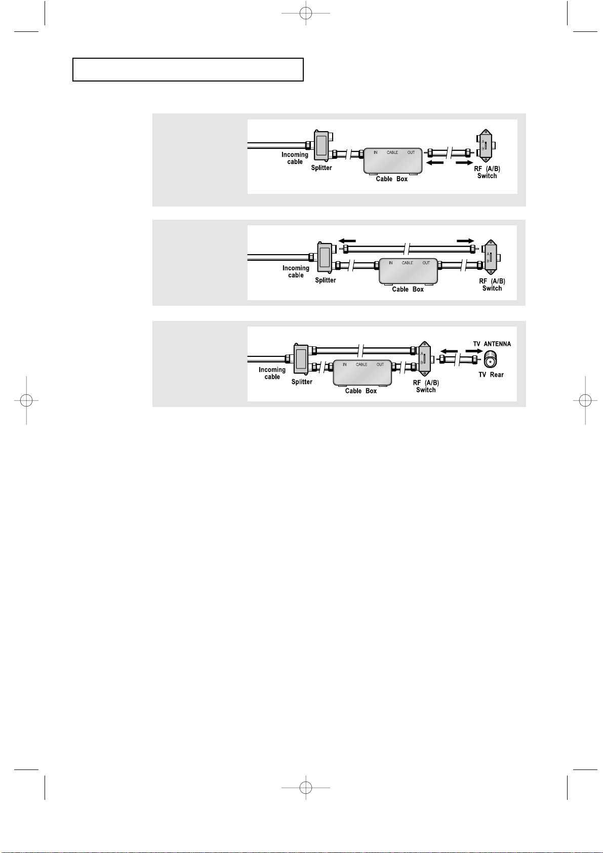
Connecting to a Cable Box that Descrambles Some Channels
If your cable box descrambles only some channels (such as premium channels), follow the
instructions below. You will need a two-way splitter, an RF (A/B) switch, and four lengths of
coaxial cable. (These items are available at most electronics stores.)
1
Find and disconnect
the cable that is
connected to the
ANTENNA IN terminal
on your cable box.
This terminal might be labeled
“ANT IN”, “VHF IN”, or simply,
“IN”.
2
Connect this cable
to a two-way splitter.
3
Connect a coaxial
cable between an
OUTPUT terminal on
the splitter and the IN
terminal on the cable
box.
06.CHAPTER2_EN 2/5/03 12:34 AM Page 3
Page 17
CHAPTER TWO: INSTALLATION 2.4
4
Connect a coaxial
cable between the
ANTENNA OUT
terminal on the
cable box and the
B–IN terminal on the
A/B switch.
5
Connect another
cable between the
other OUT terminal
on the splitter and
the A–IN terminal on
the RF (A/B) switch.
6
Connect the last
coaxial cable
between the OUT
terminal on the RF
(A/B) switch and the
VHF/UHF terminal
on the rear of the
TV.
INSTALLATION
After you’ve made this connection, set the A/B switch to the “A” position for normal
viewing. Set the A/B switch to the “B” position to view scrambled channels.
(When you set the A/B switch to “B,” you will need to tune your TV to the cable box’s
output channel, which is usually channel 3 or 4.)
06.CHAPTER2_EN 2/5/03 12:34 AM Page 4
Page 18
2.5 CHAPTER TWO: INSTALLATION
INSTALLATION
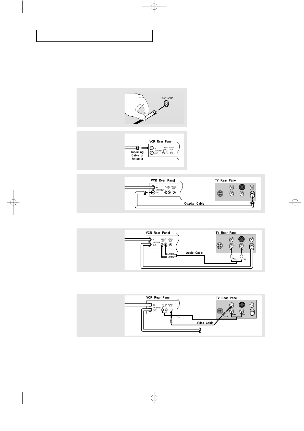
3
Connect a coaxial
cable between the
ANTENNA OUT
terminal on the VCR
and the antenna
terminal on the TV.
4
Connect a set of
audio cables
between the AUDIO
OUT jacks on the
VCR and the AUDIO
jacks on the TV.
5
Connect a video
cable between the
VIDEO OUT jack on
the VCR and the
VIDEO jack on the
TV.
Follow the instructions in “Viewing a VCR or Camcorder Tape” to view your VCR tape.
A coaxial cable is usually included with a VCR. (If not, check your local electronics store).
If you have a “mono” (non-stereo) VCR, use the Y-connector (not supplied) to hook up
to the left and right audio input jacks of the TV. If your VCR is stereo, you must connect
two cables.
Connecting a VCR
These instructions assume that you have already connected your TV to an antenna or a cable
TV system (according to the instructions on pages 2.1-2.3).
Skip step 1 if you have not yet connected to an antenna or a cable system.
1
Unplug the cable or
antenna from the
back of the TV.
2
Connect the cable or
antenna to the
ANTENNA IN terminal
on the back of the
VCR.
06.CHAPTER2_EN 2/5/03 12:34 AM Page 5
Page 19
CHAPTER TWO: INSTALLATION 2.6
INSTALLATION
3
Connect an S-video
cable between the
S-VIDEO OUT jack on
the VCR and the
S-VIDEO INPUT jack
on the TV.
An S-video cable is usually included with an S-VHS VCR. (If not, check your local
electronics store.)
1
To begin, follow
steps 1–3 in the
previous section to
connect the antenna
or cable to your
VCR and your TV.
Connecting an S-VHS VCR
Your Samsung TV can be connected to an S-Video signal from an S-VHS VCR.
(This connection delivers a better picture as compared to a standard VHS VCR.)
2
Connect a set of audio
cables between the
AUDIO OUT jacks on
the VCR and the
AUDIO INPUT jacks on
the TV.
06.CHAPTER2_EN 2/5/03 12:34 AM Page 6
Page 20
2.7 CHAPTER TWO: INSTALLATION
INSTALLATION
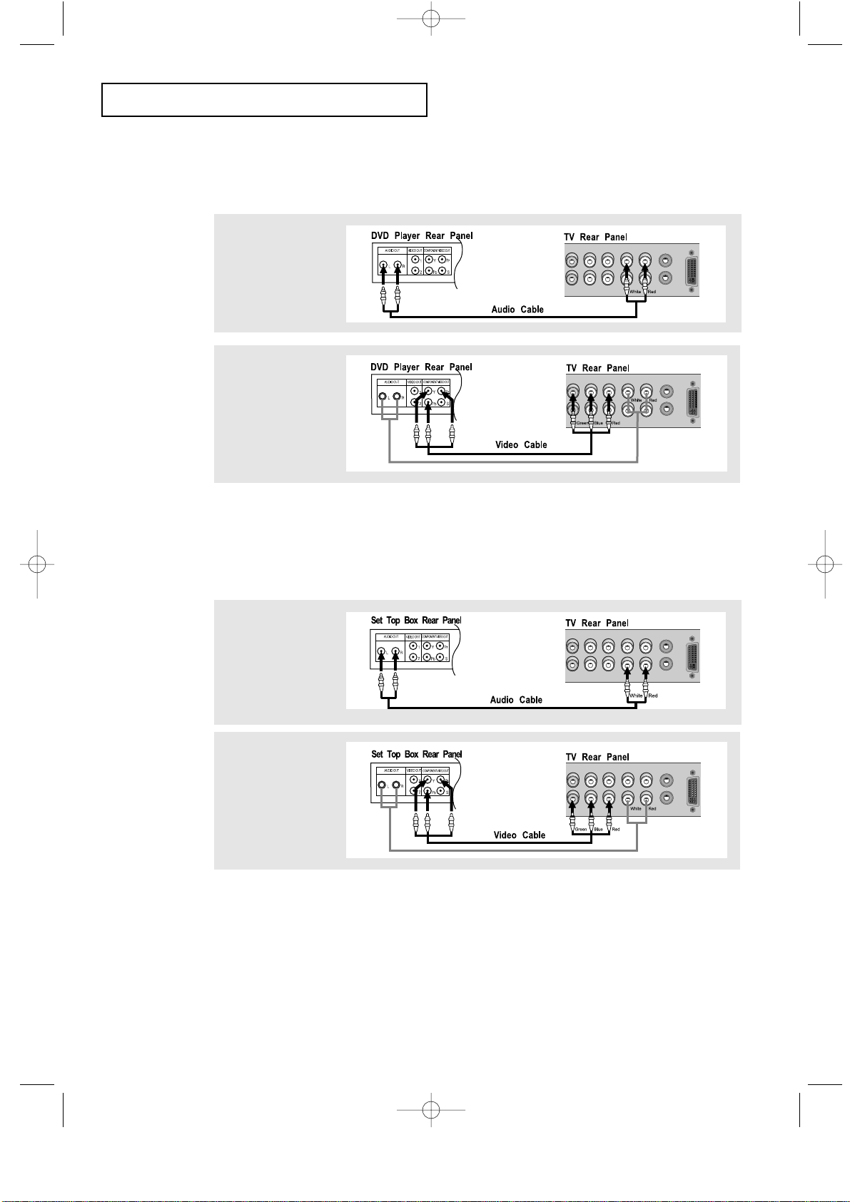
Note: For an explanation of Component video, see your DVD player owner's manual.
Connecting a DVD Player
The rear panel jacks on your TV make it easy to connect a DVD player to your TV.
1
Connect a set of audio
cables between the
L, R AUDIO INPUT
jacks on the TV and
the AUDIO OUT jacks
on the DVD player.
2
Connect a video cable
between the
COMPONENT1
(Y, Pb, Pr) jacks on
the TV and the Y, Pb,
Pr jacks on the DVD
player.
Note: For an explanation of Component video, see your Set-Top Box owner's manual.
Connecting a Digital TV Set-Top Box
The connections for a typical set-top box are shown below.
1
Connect a set of audio
cables between the
L, R COMPONENT2
AUDIO INPUT jacks
on the TV and the
AUDIO OUT jacks on
the Set-Top Box.
2
Connect a video cable
between the
COMPONENT2
(Y, Pb, Pr) jacks on
the TV and the Y, Pb,
Pr jacks on the
Set-Top Box.
06.CHAPTER2_EN 2/5/03 12:34 AM Page 7
Page 21
CHAPTER TWO: INSTALLATION 2.8
INSTALLATION
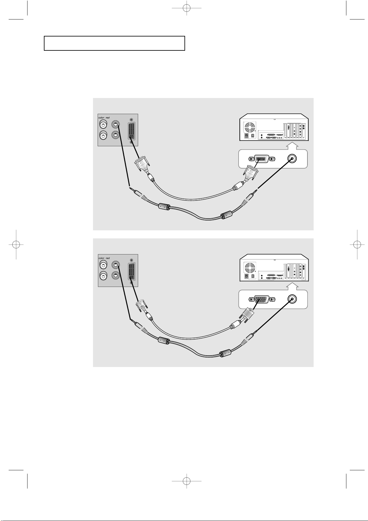
Connecting a PC
Note: This figure shows the Standard Connector-jack panel. The actual configuration on
your TV may be different, depending on the model.
PC VIDEO CABLE
( DVI-D+DVI-D )
PC AUDIO CABLE
• PC AUDIO INPUT
Connect these to the audio-output jacks on your PC.
• PC VIDEO INPUT
Connect to the video output port on your PC.
TV rear panel PC rear
TV rear panel PC rear
DVI-D
D-SUB
06.CHAPTER2_EN 2/5/03 12:34 AM Page 8
PC VIDEO CABLE
( DVI + D-SUB)
PC AUDIO CABLE
Page 22
2.9 CHAPTER TWO: INSTALLATION
INSTALLATION
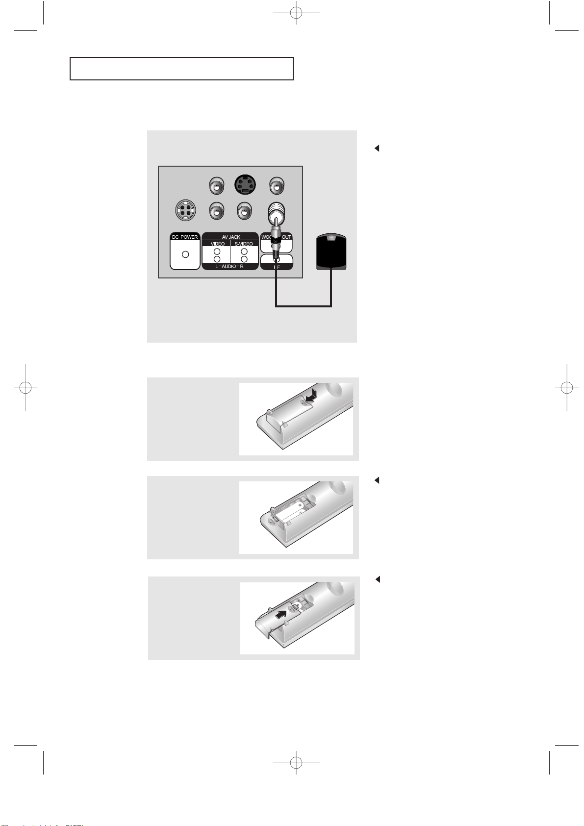
Connecting to a Sub-woofer.
3
Replace the cover.
Remove the batteries and store them
in a cool, dry place if you won’t be
using the remote control for a long
time.
The remote control can be used
up to about 23 feet from the TV.
(Assuming typical TV usage,
the batteries last for about one year.)
2
Install two AA size
batteries.
Make sure to match the “+” and
“
–” ends of the batteries with the
diagram inside the compartment.
Connect an audio cable between
the INPUT jack on an active
(powered) Sub woofer and the
WOOFER OUT jack on the TV.
Installing Batteries in the Remote Control
1
Slide the cover out
completely.
06.CHAPTER2_EN 4/24/03 9:24 PM Page 9
Page 23

CHAPTER THREE:TVOPERATION 3.1
Chapter Three
OPERATION
Turning the TV On and Off
Press the POWER button.
You can also use the Power button on the front panel.
Plug & Play Feature
When the TV is initially powered On, two basic customer settings proceed
automatically and subsequently: Setting Auto program, Clock.
1
Press the POWER
button on the remote
control.
The message “Plug &
Play” is displayed.
It flickers for a little while,
then the “Language”
menu is automatically
displayed.
2
Press the
LEFT/RIGHT
button to select the
desired language.
Press the MENU button
to enter the language,
and then the “Time”
menu is automatically
displayed.
3
Press the LEFT/RIGHT
buttons to move
to the hour or minute.
Set the hour or minute
by pressing the
UP/DOWN buttons.
(refer to “Setting and
Displaying the Current
Time” on page 3.9.)
07.CHAPTER3_EN 2/5/03 12:34 AM Page 1
Page 24

3.2 CHAPTER THREE:TVOPERATION
OPERATION
4
Press the LEFT/RIGHT
button to select
the desired video signal
source.
Press the MENU button
to enter the video signal
source, and then the
“Ant Input check” is
automatically displayed.
5
Make sure that the
antenna is connected
to the TV.
Press the LEFT/RIGHT
button to activate
"Auto Program" or press
the MENU button to skip.
(refer to “Auto program”
on page 3.6.)
6
The message
“Enjoy your watching.”
is displayed.
7
If you want to reset this
feature
(1) Press the MENU
button.
(2) Press the DOWN
button to highlight the
“Function” menu and
press the RIGHT
button.
(3) Press the DOWN
button to select Plug
& Play and press the
RIGHT button.
The message “Plug &
Play” is displayed.
07.CHAPTER3_EN 2/5/03 12:34 AM Page 2
Page 25

CHAPTER THREE:TVOPERATION 3.3
OPERATION
Viewing the Display
The display identifies the current channel and the status
of certain audio-video settings.
The on-screen displays
disappear after about ten seconds.
Viewing the Menus and On-Screen Displays
Viewing the Menus
1
With the power on, press
the MENU button.
The main menu appears
on the screen. Its left
side has five icons:
Picture, Sound, Channel,
Function and PC.
The on-screen menus
disappear from the screen after
about thirty seconds.
You can also use the MENU,
CHANNEL, and VOLUME
buttons on the control panel of
the TV to make selections.
1
Press the Display
button on the remote
control.
The TV will display the
channel, the type of
sound, and the status
of certain picture and
sound settings.
2
Use the UP/DOWN buttons to select one of the
5 icons. Then press RIGHT to access the icon’s
sub-menu.
3
Press the MENU button to exit.
07.CHAPTER3_EN 2/5/03 12:34 AM Page 3
Page 26

3.4 CHAPTER THREE:TVOPERATION
OPERATION
Selecting a Menu Language
3
Press the RIGHT button to select the appropriate
language: English, Spanish, French or Polish.
4
Press the MENU button to exit.
2
Press the DOWN
button to select
Language.
1
Press the MENU button
to display the menu.
Press the DOWN
button to select
“Function”, then press
the RIGHT button.
07.CHAPTER3_EN 2/5/03 12:34 AM Page 4
Page 27

CHAPTER THREE:TVOPERATION 3.5
OPERATION
Memorizing the Channels
Your TV can memorize and store all of the available channels for both “off-air” (antenna)
and cable channels. After the available channels are memorized, use the CH and CH
buttons to scan through the channels. This eliminates the need to change channels by
entering the channel digits. There are three steps for memorizing channels: selecting a
broadcast source, memorizing the channels (automatic) and adding and deleting channels
(manual).
Selecting the Video Signal-source
Before your television can begin memorizing the available channels, you must specify the
type of signal source that is connected to the TV (i.e., an antenna or a cable system).
1
Press the MENU button
to display the menu.
Press the DOWN
button to select
“Channel”, then press
the RIGHT button.
2
Repeatedly press the
RIGHT button to
cycle through these
choices:
ANT (antenna), STD,
HRC or IRC (all cable
TV).
Note : STD, HRC and IRC identify various types of cable
TV systems. Contact your local cable company to identify the
type of cable system that exists in your particular area.
At this point the signal source has been selected.
Proceed to “Storing Channels in Memory” (next page).
07.CHAPTER3_EN 2/5/03 12:34 AM Page 5
Page 28

3.6 CHAPTER THREE:TVOPERATION
3
Press the RIGHT
button.
The TV will begin
memorizing all of the
available channels.
OPERATION
Storing Channels in Memory (Automatic Method)
The TV automatically cycles
through all of the available
channels and stores them in
memory. This takes about one to
two minutes.
Press RIGHT at any time to
interrupt the memorization process
and return to the CHANNEL menu.
2
Press the DOWN
button to select
“Auto program”.
1
First, select the correct
signal source (ANT,
STD, HRC, IRC). See
steps 1~2 on previous
page.
Press the MENU
button.
Press the DOWN
button to select
“Channel”, then press
the RIGHT button.
4
After all the available channels are stored, the Auto
program menu reappears. Press the MENU button to
exit.
07.CHAPTER3_EN 2/5/03 12:34 AM Page 6
Page 29

CHAPTER THREE:TVOPERATION 3.7
OPERATION
Changing Channels
Using the Channel Buttons
1
Press the CH / buttons to change channels.
When you press the CH / buttons, the TV changes channels in sequence.
You will see all the channels that the TVhas memorized. (The TV must have
memorized at least three channels.) You will not see channels that were either erased
or not memorized.
Directly Accessing Channels
Use the number buttons to quickly tune to any channel.
1
Press the number buttons to go directly to a channel.
For example, to select channel 27, press “2,”then “7.” The TV will change
channels when you press the second number.
When you use the number buttons, you can directly select channels that were
either erased or not memorized.
To select a channel over 100, press the +100 button.
(For channel 122, press “+100,” then “2,” then “2.”)
To change to single-digit channels (0–9) faster, press “0” before the
single digit. (For channel “4,” press “0,” then “4.”)
2
Press the ADD/ERASE button.
Repeatedly pressing this button will alternate between “Added” and “Erased.”
You can view any channel (including an erased channel) by using the number
buttons on the remote control.
1
Use the number buttons to directly select the channel that will be added or
erased.
Adding and Erasing Channels (Manual Method)
Using the Pre-CH Button to select the Previous Channel
1
Press the PRE-CH button.
The TV will switch to the last channel viewed.
To quickly switch between two channels that are far apart, tune to one channel, then
use the number button to select the second channel. Then, use the PRE-CH button
to quickly alternate between them.
07.CHAPTER3_EN 2/5/03 12:34 AM Page 7
Page 30

3.8 CHAPTER THREE:TVOPERATION
OPERATION
Adjusting the Volume
1
Press the VOL +/– buttons to increase or decrease the volume.
1
Press MUTE and the sound cuts off.
The word “Mute” will appear in the lower-left corner of the screen.
2
To turn mute off, press the MUTE button again, or simply
press either the VOL +/– button.
Using Mute
At any time, you can temporarily cut off the sound using the Mute button.
07.CHAPTER3_EN 2/5/03 12:34 AM Page 8
Page 31

CHAPTER THREE:TVOPERATION 3.9
OPERATION
Setting the Clock
Setting the clock is necessary in order to use the various timer features of the TV.
Also, you can check the time while watching the TV. (Just press DISPLAY.)
1
Press the MENU button
to display the on-screen
menu.
Press the DOWN
button three times to
select “Function”, then
press the RIGHT
button.
3
Press the
RIGHT
button. Press the
UP/DOWN
buttons repeatedly until
the correct hour appears.
After the hour is entered,
press the
RIGHT
button.
2
Press the DOWN
button to select
“Time”, then press the
RIGHT button.
4
Press the RIGHT
button again. Press the
UP/DOWN buttons
repeatedly until the
correct minutes appear.
After the minutes are
entered, press the
RIGHT button.
Press the MENU button
to exit.
When selecting the hours, be sure
to select the proper time of day
(AM or PM).
You can change the hours by
pressing the LEFT/RIGHT
buttons repeatedly
(or by holding down either of
these buttons).
The time will appear every time
you press the Display button.
07.CHAPTER3_EN 2/5/03 12:34 AM Page 9
Page 32

3.10 CHAPTER THREE:TVOPERATION
OPERATION
1
Press the MENU button
to display the menu.
Press the RIGHT
button to display the
Picture menu.
Customizing the Picture
You can use the on-screen menus to change the contrast, brightness, sharpness,
color and tint according to personal preference.
(Alternatively, you can use one of the “automatic” settings. See next page.)
2
Press the
UP/DOWN
buttons to select a
particular item.
3
Press the
LEFT/RIGHT
buttons to increase or
decrease the value of
a particular item.
For example, if you
select “Contrast”,
pressing RIGHT
increases it.
Press the MENU button
to exit.
The customer can select Color Tone:
“Cool 2”, “Cool 1”, “Normal”,
“Warm 1”, “Warm 2” according to
personal preference.
07.CHAPTER3_EN 2/5/03 12:34 AM Page 10
Page 33

CHAPTER THREE:TVOPERATION 3.11
OPERATION
Using Automatic Picture Settings
Your TV has two automatic picture settings (“Standard”, “Mild” and “Dynamic”) that
are preset at the factory. You can activate either Standard, Mild or Dynamic by pressing
P.MODE (or by making a selection from the menu). Or, you can select “Custom” which
automatically recalls your personalized picture settings.
• Choose Standard for the standard factory settings.
• Choose Movie (“Movie Contrast”) when viewing the TV in low light, or when
playing video games.
• Choose Dynamic to increase the clarity and sharpness of the picture.
• Choose Custom if you want to adjust the settings accordings to personal
preference (see “Customizing the Picture, page 3.10).
1
Press the MENU button
to display the menu.
Press the RIGHT
button to display the
Picture menu.
2
Press the
LEFT/RIGHT
buttons to select the
“Standard”, “Movie”,
“Dynamic” or “Custom”
picture setting.
Alternate method:
Simply press the P.MODE button on the remote
control to select one of the standard picture settings.
07.CHAPTER3_EN 2/5/03 12:34 AM Page 11
Page 34

3.12 CHAPTER THREE:TVOPERATION
OPERATION
2
Press the DOWN
button to select
“Equalizer”, then press
the RIGHT button.
1
Press the MENU button
to display the menu.
Press the DOWN
button to select
“Sound”, then press the
RIGHT button.
Customizing the Sound
The sound settings can be adjusted to suit your personal preference.
(Alternatively, you can use one of the “automatic” settings. See next page.)
3
Press the
LEFT/RIGHT
buttons to select a
particular item to be
changed.
Press the
UP/DOWN
buttons to increase or
decrease the value of a
particular item.
Press the MENU button
to exit.
07.CHAPTER3_EN 2/5/03 12:34 AM Page 12
Page 35

CHAPTER THREE:TVOPERATION 3.13
Using Automatic Sound Settings
Your TV has four automatic sound settings (“Standard”, “Music”, “Movie” and “Speech”)
that are preset at the factory. You can activate any of them by pressing the S.MODE
button (or by making a selection from the on-screen menu). Or, you can select “Equalizer”,
which automatically recalls your personalized sound settings.
• Choose Standard for the standard factory settings.
• Choose Music when watching music videos or concerts.
• Choose Movie when watching movies.
• Choose Speech when watching a show that is mostly dialogue (i.e., news).
• Choose Custom to recall your personalized settings.
2
Press the
LEFT/RIGHT
buttons repeatedly to
select the “Standard”,
“Music”, “Movie”,
“Speech” or “Custom”
sound settings.
1
Press the MENU button
to display the menu.
Press the DOWN
button to select
“Sound”, then press the
RIGHT button.
OPERATION
Alternate method:
Simply press the the S.MODE button on the remote
control to select one of the standard sound settings.
07.CHAPTER3_EN 2/5/03 12:34 AM Page 13
Page 36

3.14 CHAPTER THREE:TVOPERATION
OPERATION
Viewing a VCR or Camcorder Tape
You must select the appropriate mode in order to view the VCR or Camcorder signal on the TV.
1
Press the MENU button
to display the menu.
Press the DOWN
button to select
“Channel”, then press
the RIGHT button.
2
Press the DOWN
button to select
“TV/Video”.
3
Press the
LEFT/RIGHT button.
You will switch between
viewing the signals
coming from equipment
connected to the TV’s
A/V jacks, and the TV
signal.
Quick way to access the externa signal:
Simply press the TV/VIDEO button on
the remote control.
07.CHAPTER3_EN 2/5/03 12:34 AM Page 14
Page 37

CHAPTER FOUR:SPECIAL FEATURES 4.1
Chapter Four
SPECIAL FEATURES
Setting Up Your Remote Control
After it has been set up properly, your remote control can operate in four different modes:
TV, VCR, Cable, or DVD. Pressing the corresponding button on the remote control allows
you to switch between these modes, and control whichever piece of equipment you choose.
Note
The remote control might not be compatible with all DVD Players, VCRs and Cable boxes.
Note on Using Remote Control Modes: VCR
When your remote control is in “VCR” mode, the volume buttons still control your TV’s volume.
Setting Up the Remote to Operate Your VCR
1Turn off your VCR.
2Press the MODE button and make sure that the VCR LED
is illuminated.
3Press the Set button on your TV’s remote control.
4Using the number buttons on your remote control, enter
three digits of the VCR code listed on page 4.4 of this
manual for your brand of VCR. Make sure you enter three
digits of the code, even if the first digit is a “0”.
(If more than one code is listed, try the first one.)
5Press the Power button on the remote control. Your VCR
should turn on if your remote is set up correctly.
If your VCR does not turn on after set up, repeat steps
2, 3, and 4, but try one of the other codes listed for your
brand of VCR. If no other codes are listed, try each VCR
code, 000 through 089.
08.CHAPTER4_EN 2/5/03 12:34 AM Page 1
Page 38

4.2 CHAPTER FOUR:SPECIAL FEATURES
Setting Up the Remote to Operate Your Cable Box
Note on Using Remote Control Modes: Cable Box
When your remote control is in “Cable Box” mode, the volume buttons still control your TV’s volume.
1Turn off your cable box.
2Press the MODE button and make sure that the Cable LED is
illuminated.
3Press the SET button on your TV’s remote control.
4Using the number buttons on your remote control, enter three
digits of the cable box code listed on page 4.4 of this manual
for your brand of cable box. Make sure you enter three digits
of the code, even if the first digit is a “0.”
If there is more than one code listed, try the first one.
5Press the Power button on the remote control. Your cable box
should turn on if your remote is set up correctly.
If your cable box does not turn on after set up, repeat steps
2, 3, and 4, but try one of the other codes listed for your brand
of cable box. If no other codes are listed, try each code, 000
through 077.
08.CHAPTER4_EN 2/5/03 12:34 AM Page 2
Page 39

CHAPTER FOUR:SPECIAL FEATURES 4.3
Setting Up the Remote to Operate Your DVD
Note on Using Remote Control Modes: DVD
When your remote control is in “DVD” mode, the volume buttons still control your TV’s volume.
1Turn off your DVD.
2Press the MODE button and make sure that the DVD LED is
illuminated.
3Press the SET button on your TV’s remote control.
4Using the number buttons on your remote control, enter three
digits of the DVD code listed on page 4.4 of this manual for
your brand of DVD. Make sure you enter three digits of the
code, even if the first digit is a “0.”
If there is more than one code listed, try the first one.
5Press the Power button on the remote control. Your DVD should
turn on if your remote is set up correctly.
If your DVD does not turn on after set up, repeat steps 2, 3, and
4, but try one of the other codes listed for your brand of DVD.
If no other codes are list-ed, try each code, 000 through 008.
Setting Up the Remote to Operate Your DVD
08.CHAPTER4_EN 2/5/03 12:34 AM Page 3
Page 40

4.4 CHAPTER FOUR:SPECIAL FEATURES
Remote Control Codes
Admiral
Aiwa
Audio Dynamics
Bell&Howell
Broksonic
Candle
Canon
Citizen
Colortyme
Craig
Curtis-Mathes
Daewoo
DBX
Dimensia
Dynatech
Electrohome
Emerson
Fisher
Funai
GE
Go Video
Harman Kardon
Hitach
Instant Replay
JC Penney
JCL
JVC
kenwood
015,088
024
022,025
011
019
016,018,022,054,055,061
017,062
016,018,022,054,055,061
023
016,021
009,016,017,023,024,055,062,073,076
003,004,005,006,007,008,022,054,085
009
024
036
017,018,019,022,024,029,032,036,043,
050,051,056,058,066,071,074,076,077,079
011,021,027,028,052,057,067
024
016
023
014,024,044,045
017
011,014,016,017,023,025,039,044,060,062
011,017,023,025,039,055
011,023,025,039,055
015,016
015,016
015,016
054
012,013,023,031,032,
033,038,044,075,076,077
011,012,020,021,042,056
045,051,054
012,013,023,031,032,033,038,044,054,070,073
045,051
015,016,027,029,034,036,037,040,041,048,049
007
008
008
002
006
004
000
017
024,046
024
011,035,047,069
015,016,027,029,034,036,037,040,041,048,049
026,028,052
015,016
008,035,074
011,020,021
010,041
000,011,030,052,071,072
054
035
054
066
019,067
019,067
025,029,057,058,063
039,040,049
059,060
015,016,027,029,034,036,037,040,041,048,049
052
022,050,065,069
082
001,002,007
024
040
024
017,038,062,065
011,017,023,025,038,039,055,070
016,024
016,024,040,041
011,023,025,039,055,070,073
015
017,062,084,086
014,044
055
017,038,062,065
017,038
014,025,042,059
053,054,061
009
011
017,053
011,015,017,018,021,
024,028,036,052,062
KLH
LG
Lloyd
Logik
LXI
Magnavox
Marantz
Marta
MEI
Memorex
MGA
Midland
Minota
Mitsubishi
Montgomery ward
MTC
Multitech
NEC
Optimus
Panasonic
Pentax
Pentex Reserch+
Philco
Philips
Pioneer
Portland
ProScan
Quartz
Quasar
Radio Shack/Realistics
Anvision
Cable star
Eagle
Eastrm Int.
General Instrument
GI
Hamlin
Hitachi
Jerrold
Macom
Magnavox
Philips
Proscan
RCA
Toshiba
Panasonic
Sony
Samsung
NSC
Oak
Osk Sigma
Panasonic
Philips
Pioneer
Randtek
RCA
Regal
Regency
SA
Samsung
Signature
Sprucer
Starcom
Stargate 2000
Sylvania
Texscan
Tocom
Unika
Universal
Viewstar
Warner Amex
Zenith
RCA
Samsung
Sansui
Sanyo
Scott
Sears
Sharp
Shintom
Signature
Sony
Sylvania
Symphonic
Tandy
Tashiko
Tatung
Teac
Technics
Temika
TMK
Toshiba
Totevision
Unitech
Vector Research
Victor
Video Concepts
Videosonic
Wards
Yamaha
Zenith
009,014,016,017,037,044,046,063,078
000,016,022,031,041,051
025
011,021
022,050,058,077
011,014,018,021,027,028,044,052,057
015,036,048,054
026,035,040,064
024
026,035,047
017,024,038,062,065
024
011,024
039
024,039,078
017
076
014,022,028,057,058
016,018
VCR Codes
Cable Box Codes
DVD Codes
08.CHAPTER4_EN 2/5/03 12:34 AM Page 4
Page 41

CHAPTER FOUR:SPECIAL FEATURES 4.5
Fine Tuning Channels
Use fine tuning to manually adjust a particular channel for optimal reception.
1
Select the appropriate
channel.
2
Press the MENU button
to display the menu.
Press the DOWN
button twice to select
“Channel”, then press
the RIGHT button.
3
Press the DOWN
button to select
“Fine Tune.”
4
Press the RIGHT
and LEFT butons
to adjust the fine tuning.
5
To store the fine tuning
setting in the TV’s
memory, press the
UP button.
(A heart icon will appear.)
To reset the fine tuning
to “00”, press the
DOWN button.
Press the MENU button
to exit.
After you adjust the fine tuning,
the “MFT” will appear when you
press Display while watching this
channel.
SPECIAL FEATURES
08.CHAPTER4_EN 2/5/03 12:34 AM Page 5
Page 42

4.6 CHAPTER FOUR:SPECIAL FEATURES
SPECIAL FEATURES
LNA (Low Noise Amplifier)
If the TV is operating in a weak-signal area, sometimes the LNA function can improve
the reception (a low-noise preamplifier boosts the incoming signal).
2
Press the DOWN
button to select “LNA”.
3
Press the
LEFT/RIGHT
button to set LNA “On”.
Press the MENU button
to exit.
1
Press the MENU button
to display the menu.
Press the DOWN
button to select
“Channel”, then press
the RIGHT button.
Pressing LEFT/RIGHT will
alternate between “On” and “Off”.
08.CHAPTER4_EN 2/5/03 12:34 AM Page 6
Page 43

CHAPTER FOUR:SPECIAL FEATURES 4.7
SPECIAL FEATURES
Setting the Blue Screen Mode
If no signal is being received or the signal is very weak, a blue screen automatically
replaces the noisy picture background.
If you wish to continue viewing the poor picture, you must set the “Blue screen”
mode to “Off”.
1
Press the MENU button
to display the menu.
Press the DOWN
button to select
"Function", then press
the RIGHT button.
2
Press the DOWN
button to select
"Blue Screen."
3
Press the
LEFT/RIGHT
buttons to set Blue
Screen “On”.
Press the MENU button
to exit.
Pressing the LEFT/RIGHT
buttons will alternate between
“On” and “Off”.
08.CHAPTER4_EN 2/5/03 12:34 AM Page 7
Page 44

4.8 CHAPTER FOUR:SPECIAL FEATURES
Freezing the Picture
1
Press the STILL button to freeze a moving picture.
"main picture".
• Normal sound will still be heard.
Press again it cancel.
SPECIAL FEATURES
Changing the Screen Size
1
Press the P.SIZE button to change the screen size.
• Wide: Sets the picture to 16:9 wide mode.
• Panorama : Use this mode for the wide aspect ratio of a panoramic picture.
(However, it does not work in 720p and 1080i modes.)
• Zoom 1,2 : Magnifies the size of the picture on screen.
• Normal: Sets the picture to 4:3 normal mode.
This is the standard TV screen size.
08.CHAPTER4_EN 2/5/03 12:34 AM Page 8
Page 45

CHAPTER FOUR:SPECIAL FEATURES 4.9
SPECIAL FEATURES
Special Sound Options
Choosing a Multi-Channel Sound (MTS) Soundtrack
Depending on the particular program being broadcast, you can listen to stereo, mono, or
a Separate Audio Program. (SAPaudio is usually a foreign-language translation.
Sometimes SAP has unrelated information like news or weather.)
2
Press the DOWN
button three times to
select “MTS”.
3
Press the RIGHT
button repeatedly to
select “Mono”, “SAP”,
or “Stereo”.
Press the MENU
button to exit.
The text at the bottom of the menu
tells you if the incoming audio is
stereo, SAP, or mono.
1
Press the MENU button
to display the menu.
Press the DOWN
button to select
“Sound”, then press the
RIGHT button
• Choose Stereo for channels that are broadcasting in stereo.
• Choose Mono for channels that are broadcasting in mono, or if you are
having difficulty receiving a stereo signal.
• Choose SAP to listen to the Separate Audio Program, which is usually a
foreign-language translation.
You can also change the MTS setting by pressing the “MTS” button on the remote
control. (When you change channels, MTS is set to “Stereo” automatically.
To listen in ‘SAP’ or ‘Mono’, change the MTS setting.)
08.CHAPTER4_EN 2/5/03 12:34 AM Page 9
Page 46

4.10 CHAPTER FOUR:SPECIAL FEATURES
SPECIAL FEATURES
Auto Volume
Each broadcasting station has its own signal conditions, and it is inconvenient to adjust
the volume every time the channel is changed. “Auto volume” automatically adjusts the
volume of the desired channel by lowering the sound output when the modulation signal
is high or by raising the sound output when the modulation signal is low.
2
Press the DOWN
button to select
“Auto volume”.
3
Press the RIGHT
button to select “On”.
Press the MENU button
to exit.
1
Press the MENU button
to display the menu.
Press the DOWN
button to select
“Sound”, then press the
RIGHT button.
Pressing LEFT/RIGHT will
alternate between “On” and “Off”.
08.CHAPTER4_EN 2/5/03 12:34 AM Page 10
Page 47

CHAPTER FOUR:SPECIAL FEATURES 4.11
SPECIAL FEATURES
Virtual Dolby
This feature allows the TV’s L/R speakers to provide a home Theater-like Dolby effect.
The center and surround sounds are mixed into the L/R speakers.
2
Press the DOWN
button to select
“Virtual Dolby”.
3
Press the RIGHT
button to select “On”.
Press the MENU button
to exit.
1
Press the MENU button
to display the menu.
Press the DOWN
button to select
“Sound”, then press the
RIGHT button
Pressing LEFT/RIGHT will
alternate between “On” and “Off”.
Quick way to access the
Virtual Dolby menu: Simply press
the Dolby Virtual button on the
remote control.
08.CHAPTER4_EN 2/5/03 12:34 AM Page 11
Page 48

4.12 CHAPTER FOUR:SPECIAL FEATURES
SPECIAL FEATURES
Adjusting the Headphone Sound
The headphone option is especially useful when simultaneously watching the main
screen and the PIP window.
1
Press the MENU button
to display the menu.
Press the DOWN
button to select
“Sound”, then press the
RIGHT button
2
Press the DOWN
button to select
“Headphone” and press
the RIGHT button.
Note :Headphones must be
purchased separately.
3
Press the
UP/DOWN button
to select the particular
item to be changed.
Note :When you want to
listen to TV with headphones
only, press the MUTE or
VOL- button on the remote
control to set the TV speaker
volume to zero(0).
4
Press the
LEFT/RIGHT
buttons to increase or
decrease the value of a
particular item.
Press the MENU button
to exit.
08.CHAPTER4_EN 2/5/03 12:34 AM Page 12
Page 49

CHAPTER FOUR:SPECIAL FEATURES 4.13
SPECIAL FEATURES
Note :Sound Select can also
be used to select the
Main or Sub sound
over the speakers.
Selecting the Sound
You can select either Main or Sub when PIP is On.
1
Press the MENU button
to display the menu.
Press the DOWN
button to select
“Sound”, then press the
RIGHT button.
2
Press the DOWN
button to select
“Sound Select”.
3
Press the RIGHT
button to select
“Main” or “Sub”.
Select “Main” to hear
the main TV sound and
select “Sub” to hear the
PIP window sound.
Press the MENU button
to exit.
08.CHAPTER4_EN 2/5/03 12:34 AM Page 13
Page 50

4.14 CHAPTER FOUR:SPECIAL FEATURES
SPECIAL FEATURES
Setting the On/Off Timer
1
Press the MENU button
to display the on-screen
menu.
Press the DOWN
button three times to
select “Function”, then
press the RIGHT
button.
Before using the timer, you must
set the TV’s clock.
(See “Setting the Clock” on page 3.9)
2
Press the DOWN
button to select the
“Time”, then press the
RIGHT button.
3
Press the DOWN
button to select “On
time”, then press the
RIGHT button.
Press the
UP/DOWN buttons
repeatedly to select the
appropriate hours (i.e.,
the hour when the TV
will turn on).
When you set the hours, make sure
the correct time of day (AM or PM)
appears to the left of the hour.
4
Press the RIGHT
button to select the
“On time” minutes.
Press the
UP/DOWN buttons
repeatedly to select the
appropriate minutes.
continued...
08.CHAPTER4_EN 2/5/03 12:34 AM Page 14
Page 51

CHAPTER FOUR:SPECIAL FEATURES 4.15
SPECIAL FEATURES
5
Press the RIGHT
button to select “On/Off”.
Press the
UP/DOWN
buttons
to on-timer “On”.
(Repeatedly pressing
the UP/DOWN
buttons will alternate
between on and off.)
When finished, press the
RIGHT button.
To deactivate the “On time,”
select “Off” during this step.
6
To set the Off time,
press the DOWN
button to select
“Off time”.
Press the RIGHT
button and set the
hours and minutes.
(Follow the same
procedure as in steps
1~5 above.)
7
When finished setting the timer, press the MENU
button to exit.
• What is Absent PowerOff?
When you set the timer on, your television will be turned
off if you do not operate any controls during 3 hours after
you turn on the TV.
This 'Absent power off' function is available in only
'Timer on' situation.
This function will prevent the leakage accident or dissipation
caused by the occation that your TV will be left in turned on
situation for a long time due to 'Timer on'.
(when you are away on holiday for example)
08.CHAPTER4_EN 2/5/03 12:34 AM Page 15
Page 52

4.16 CHAPTER FOUR:SPECIAL FEATURES
SPECIAL FEATURES
t
Misspellings and unusual
characters sometimes occur during
closed caption transmissions, especially
those of live events. There may be a
small delay before captions appear
when you change channels. These are
not malfunctions of the TV.
3
Press the
LEFT/RIGHT
buttons to turn closed
captioning on/off.
t
In caption mode, captions appear
at the bottom of the screen, and they
usually cover only a small portion of
the picture.
In text mode, information unrelated
to the program, such as news or
weather, is displayed. Text often
covers a large portion of the screen.
4
Press the DOWN button
to select “Mode”.
Press the
LEFT/RIGHT
buttons to select
“Caption” or “Text”.
Viewing Closed Captions
Your TV decodes and displays the closed captions that are broadcast with certain TV shows.
These captions are usually subtitles for the hearing impaired or foreign-language translations.
All VCRs record the closed caption signal from television programs, so home-recorded video
tapes also provide closed captions. Most pre-recorded commercial video tapes provide closed
captions as well. Check for the closed caption symbol in your television schedule and on the
tape’s packaging:
.
Note: The Caption feature does not work with DVD or DTV signals.
1
Press the MENU button
to display the menu.
Press the DOWN
button to select
“Function”, then press
the RIGHT button.
2
Press the DOWN
button to select
“Caption”, then press
the RIGHT button.
5
Depending on the particular broadcast, it might be
necessary to make changes to “Channels” and “Field”:
Use the UP , DOWN , RIGHT and LEFT buttons
to make the changes. (Follow the same procedure as in
steps 3~4 above.)
Press the MENU button to exit.
Different channels and fields display
different information: Field 2 carries
additional information that
supplements the information in
Field 1. (For example, Channel 1
may have subtitles in English, while
Channel 2 has subtitles in Spanish.)
08.CHAPTER4_EN 2/5/03 12:34 AM Page 16
Page 53

CHAPTER FOUR:SPECIAL FEATURES 4.17
SPECIAL FEATURES
Viewing Picture-in-Picture
This product has one tuner built-in, which does not allow PIP to function in the
same mode. Please see 'PIP Settings' below for details.
You can use the PIP feature to simultaneously watch two video sources.
Note: While V-Chip is in operation, the PIP function cannot be used.
Activating Picture-in-Picture
PIP Settings
1
Press the MENU button
to display the menu.
Press the DOWN to
select “PIP”, then
press the RIGHT
button.
2
Press the RIGHT
button to select PIP
“On”.
If you turn the TV off while watching
and turn it on again, the PIP window
will disappear.
3
Press the MENU button to exit.
Note: Picture-in-Picture does not function when the
V-chip is active.
Quick way to access the PIP menu:
Simply press the PIP button on the
remote control.
08.CHAPTER4_EN 2/5/03 12:34 AM Page 17
Page 54

4.18 CHAPTER FOUR:SPECIAL FEATURES
SPECIAL FEATURES
Press the TV/VIDEO(PIP) button repeatedly to cycle
through all of the available signal sources:
“TV”, “Video”, “S-Video”, “Component 1” and “Component 2”.
For more information about
external A/V components and
signals, see “Viewing a VCR or
Camcorder Tape” on page 3.17.
If you select “TV”, the PIP image
is the same as the main image.
While the main screen is in
PC mode, it does not work.
When you press the SWAP button,
the image in the PIP window will appear on the main
screen, and vice versa.
Swapping the Contents of the PIP image and Main image
Selecting a Signal Source (External A/V) for PIP
Press the PIP CH / button to change the channel
that appears in the PIP window.
Changing the PIP Channel
When you press the LOCATE button repeatedly,
the PIP window moves from corner to corner on the
TV screen.
Changing the Location of the PIP Window
Press the P.SIZE button to alternate between a
smaller and larger PIP window.
Changing the Size of the PIP Window
08.CHAPTER4_EN 2/5/03 12:35 AM Page 18
Page 55

CHAPTER FOUR:SPECIAL FEATURES 4.19
Using the V-Chip
The V-Chip feature automatically locks out programming that is deemed inappropriate for
children. The user must first enter a PIN (personal ID number) before any of the V-Chip
restrictions can be set up or changed.
Setting Up Your Personal ID Number (PIN)
1
Press the MENU button
to display the menu.
Press the DOWN
button to select
“Function”, then press
the RIGHT button.
2
Press the DOWN
button to select
“V-chip”, then press the
RIGHT button.
3
After entering a valid
PIN number, the
“V-chip” screen will
appear. Press the
DOWN button to
select “Change Pin.”
4
Press the RIGHT
button. The Change
pin screen will
appear. Choose any
4-digits for your PIN
and enter them.
Note: If you forget the PIN,
press the remote-control
buttons in the following
sequence,which resets the pin
to 0-0-0-0:
POWER OFF ➔ MUTE ➔
8 ➔ 2 ➔ 4 ➔ POWER ON.
SPECIAL FEATURES
As soon as the 4 digits are entered, the “Confirm new
Pin” screen appears. Re-enter the same 4 digits.
When the Confirm screen disappears, your PIN has
been memorized.
Press the MENU button to exit.
The “Enter Pin” screen will appear. Enter your 4-digit PIN
number. Note: The default PIN number for a new TV set is
“0-0-0-0.”
➜
08.CHAPTER4_EN 2/5/03 12:35 AM Page 19
Page 56

4.20 CHAPTER FOUR:SPECIAL FEATURES
How to Set up Restrictions Using the “TV guidelines”
First, set up a personal identification number (PIN), and enable the V-Chip.
(See previous section.) Parental restrictions can be set up using either of two methods:
The TV guidelines or the MPAArating.
How to Enable/Disable the V-Chip
Note: V-Chip cannot be used during PIP operation.
1
Press the MENU button
to display the menu.
Press the DOWN
button to select
“Function”, then press
the RIGHT button.
2
Press the DOWN
button to select
“V-chip”, then press the
RIGHT button.
The “Enter pin” screen
will appear. Enter your
4-digit PIN number.
3
The “V-Chip” screen will
appear, and “V-Chip lock”
will be select.
To enable the V-Chip
feature, press the
RIGHT button so that
the “V-Chip Lock” is set to
Yes.
(Pressing the RIGHT
button will alternate
between Yes and No.)
1
Press the MENU button
to display the menu.
Press the DOWN
button to select
“Function”, then press
the RIGHT button.
SPECIAL FEATURES
08.CHAPTER4_EN 2/5/03 12:35 AM Page 20
Page 57

CHAPTER FOUR:SPECIAL FEATURES 4.21
2
Press the DOWN
button to select
“V-chip”, then press the
RIGHT button.
The “Enter pin” screen
will appear. Enter your
4-digit PIN number.
3
Press the DOWN
button, to select “TV
Guidelines”, then press
the RIGHT button.
4
The “TV guidelines”
screen will appear.
Press the the UP/DOWN
buttons to select
one of the six age-based
categories:
TV-Y Young children
TV-Y7 Children 7 and over
-------------------------------------TV-G General audience
TV-PG Parental guidance
TV-14 Viewers 14 and over
TV-MA Mature audience
5
At this point, one of the TV-Ratings is selected.
Press the RIGHT button: Depending on your existing setup, a letter “U” or “B” will start blinking.
(U= Unblocked, B= Blocked)
While the “U” or ”B” is blinking, press the UP/DOWN buttons to block or unblock the category.
Press the MENU button once to save the TV guidelines. A TV-Rating will be highlighted, and no letters
will blink. To exit this screen, press the MENU again. To select a different TV-Rating, press the
UP/DOWN buttons and then repeat the process.
Note 1: The TV-Y7, TV-PG, TV-14 and TV-MA have additional options.
See the next step to change any of the following sub-ratings:
FV: Fantasy Violence
D: Sexual suggestive Dialog
L: Adult Language
S: Sexual situation
V: Violence
Note 2: The V-Chip will automatically block certain categories that are “more restrictive.” For example,
if you block “TV-Y” category, then TV-Y7 will automatically be blocked. Similarly, if you block
the TV-G category, then all the categories in the “young adult” group will be blocked
(TV-G, TV-PG, TV-14 and TV-MA). The sub-ratings (D, L, S, V) work together similarly.
(See next section.)
Note: These categories consist of
two separate groups : TV-Y and
TV-Y7 (young children through
age 7), and TV-G through TV-MA
(everybody else).
The restrictions for these two groups
work independently:
If a household includes very young
children as well as young adults,
the TV guidelines must be set up
separately for each age group.
(See next step.)
SPECIAL FEATURES
08.CHAPTER4_EN 2/5/03 12:35 AM Page 21
Page 58

4.22 CHAPTER FOUR:SPECIAL FEATURES
How to Set up Restrictions using the MPAA Ratings: G, PG,
PG-13, R, NC-17, X
The MPAA rating system uses the Motion Picture Association of America (MPAA) system,
and its main application is for movies. (Eventually, movie videocassettes will be encoded
with MPAA ratings.) When the V-Chip lock is on, the TV will automatically block any
programs that are coded with objectionable ratings (either MPAA or TV-Ratings).
6
How to set the FV, D, L, S and V sub-ratings.
First, highlight one of these TV-Ratings: TV-Y7, TV-PG, TV-14 or TV-MA
(See Step 4, on previous page).
Next, while the TV-Rating is selected, repeatedly press the RIGHT button.
This will cycle through the available sub-ratings (FV,L, S, D or V).
A blinking letter (“U” or “B”) will be displayed for each sub-rating. While the “U” or “B” is
blinking, press the UP/DOWN buttons to change the sub-rating.
Press MENU once to save the TV guidelines. A TV-Rating will be selected, and no letters will
blink. To exit this screen, press the MENU button again. To select a different TV-Rating, press the
UP/DOWN buttons and then repeat the process.
Note: The V-chip will automatically block certain categories that are “More restrictive”.
For example, if you block “L” sub-rating in TV-PG, then the “L” sub-ratings in TV-14 and
TV-MA will automatically be blocked.
7
Press the MENU button three times to clear all the screens.
(Or proceed to the next section, and set up additional restrictions based on the MPAA codes).
1
Press the MENU button
to display the menu.
Press the DOWN
button to select
“Function”, then press
the RIGHT button.
2
Press the DOWN
button to select
“V-chip”, then press the
RIGHT button.
The “Enter pin” screen
will appear. Enter your
4-digit PIN number.
SPECIAL FEATURES
08.CHAPTER4_EN 2/5/03 12:35 AM Page 22
Page 59

CHAPTER FOUR:SPECIAL FEATURES 4.23
How to Reset the TV after the V-Chip
Blocks a Channel (“Emergency Escape”)
If the TV is tuned to a restricted channel, the V-Chip will block it. The screen will go blank and the
following message will appear: “Excessive rating”.
To resume normal viewing, tune to a different channel using the number buttons. Under certain
conditions (depending on the rating of the local TV programs) the V-Chip might lock out all the
channels.
In this case, use the Menu button for an “emergency escape”:
Select the V.chip on the Menu. Enter your PIN number, and press the RIGHT button to
temporarily disable the V-Chip Lock.
4
Repeatedly press the
DOWN button to
select a particular
MPAA category. (When
a category is selected,
its color changes to
blue.) Pressing the
DOWN button will
cycle through the
MPAA categories:
G General audience (no restrictions).
PG Parental guidance suggested.
PG-13 PG-13 (Parents strongly cautioned).
R R (Restricted. Children under 17
should be accompanied by an adult).
NC-17 No children under age 17.
X X (Adults only).
NR Not rated.
3
Press the DOWN
button to select
“MPAA rating”, then
press the RIGHT
button.
SPECIAL FEATURES
While a particular category is highlighted, press the RIGHT button to activate it.
Ablinking letter (“U” or “B”) will be displayed. Press the UP/DOWN buttons to select “U” or”B”.
Press the MENU button three times to save the settings and to clear all screens.
Note: The V -Chip will automatically block any category that is “more restrictive”.
For example, if you block the “PG-13” category, then “R,” “NC-17,” and “X”will
automatically be blocked also.
08.CHAPTER4_EN 2/5/03 12:35 AM Page 23
Page 60

5.1 CHAPTER FIVE: PC DISPLAY
Chapter Five
PC DISPLAY
Using Your TV as a Computer (PC) Display
How to Set up Your PC Software (Windows only)
The Windows display-settings for a typical computer are shown below. However, the
actual screens on your PC will probably look different, depending upon your particular
version of Windows and your particular video card. Even if your actual screens look
different, the same, basic set-up information will apply in most cases.
(If not, contact your computer manufacturer or Samsung Dealer.)
First, click on “Settings” on the
Windows start menu.
While “Settings” is highlighted,
move the cursor so that “Control
Panel” is highlighted.
When the control panel screen
appears, click on “Display” and a
display dialog-box will appear.
Navigate to the “settings” tab on the
display dialog-box.
The two key variables that apply
the TV-PC interface are “resolution”
and “colors.” The correct settings
for these two variables are:
* Size (sometimes called
“resolution”): 1280 x 720 pixels
If a vertical-frequency option exists
on your display settings dialog box,
the correct value is “60” or “60 Hz”.
Otherwise, just click “OK” and exit
the dialog box.
* See “Display Mode” on page A.1.
09.CHAPTER5_EN 2/5/03 12:35 AM Page 1
Page 61

CHAPTER FIVE: PC DISPLAY 5.2
Adjusting the Screen Quality
The purpose of the picture quality adjustment is to remove or reduce picture noise. If the
noise is not removed by fine tuning alone, then do the frequency adjustments to the
utmost and fine tune again. After the noise has been reduced, re-adjust the picture so that
it is aligned on the center of screen.
Press the PC button on the remote control to select the PC mode.
1
Press the MENU button
to display the menu.
Press the DOWN
button to select “PC”,
then press the
RIGHT button.
2
Press the DOWN
button to select
“Coarse” or “Fine”.
3
Press the
LEFT/RIGHT
button to adjust the
screen quality, vertical
stripes appear or the
picture may be blurry.
4
When you are satisfied with the settings, press the
MENU button repeatedly to return to normal viewing.
PC DISPLAY
<Adjusting Coarse>
<Adjusting Fine>
09.CHAPTER5_EN 2/5/03 12:35 AM Page 2
Page 62

5.3 CHAPTER FIVE: PC DISPLAY
Changing the Screen Position
Press the PC button on the remote control to select the PC mode.
To Return the Screen Position settings to the default position.
1
Press the MENU button
to display the menu.
Press the DOWN
button to select “PC”,
then press the
RIGHT button.
Press the DOWN
button to select “Image
Recall”, then press the
RIGHT button to
return H and V positions
to their default settings.
2
Press the DOWN
button to select
“Position”, then press
the RIGHT button.
Repeatedly press
RIGHT to choose
between H-Position and
V-Position.
3
If H-Position is
selected, press the
UP/DOWN
button to select the item
you want to adjust, then
press the
LEFT/RIGHT
button to adjust the
H-Position.
Press the MENU button
to exit.
PC DISPLAY
09.CHAPTER5_EN 2/5/03 12:35 AM Page 3
Page 63

CHAPTER FIVE: PC DISPLAY 5.4
PC DISPLAY
Changing the Screen Color Standard
Press the PC button on the remote control to select the PC mode.
1
Press the MENU button
to display the menu.
Press the DOWN
button to select “PC”,
then press the
RIGHT button.
2
Press the DOWN
button to select
“Color Adjust”.
3
Press the
LEFT/RIGHT
buttons to select
“Custom”, “Color1”,
“Color2” or “Color3”.
Press the MENU button
to exit.
09.CHAPTER5_EN 2/5/03 12:35 AM Page 4
Page 64

5.5 CHAPTER FIVE: PC DISPLAY
Adjusting the Screen Color Settings
Press the PC button on the remote control to select the PC mode.
To Return the Custom settings back to the default position.
1
Press the MENU button
to display the menu.
Press the DOWN
button to select “PC”,
then press the
RIGHT button.
Press the DOWN
button to select “Color
Recall”, then press the
RIGHT button to
return R,G,B to their
default settings.
2
Press the DOWN
button to select “Color
Adjust”, then press the
RIGHT button.
Repeatedly press
RIGHT to choose
between Color 1,2, and
3 auto settings and
Custom.
3
If Custom is selected,
press the UP/DOWN
button to select
the item you want to
adjust, then press the
LEFT/RIGHT
button to adjust the
color(R, G, B).
Press the MENU button
to exit.
PC DISPLAY
09.CHAPTER5_EN 2/5/03 12:35 AM Page 5
Page 65

CHAPTER SIX: TROUBLESHOOTING 6.1
If the TV seems to have a problem, first try this list of possible problems and solutions.
If none of these troubleshooting tips apply, call your nearest Samsung service center.
Identifying Problems
Chapter Six
TROUBLESHOOTING
Problem
Poor picture
Poor sound quality.
No picture or sound.
No sound or sound is too low
at maximum volume.
No color, wrong colors or tints.
Picture rolls vertically.
The TV operates erratically .
The TV won’t turn on.
Blurred or snowy picture,
distorted sound.
Remote control malfunctions
“Check Signal Cable”
message.
Possible Solution
Try another channel.
Adjust the antenna.
Check all wire connections.
Try another channel.
Adjust the antenna.
Try another channel.
Press the TV/VIDEO button.
Make sure the TV is plugged in.
Check the antenna connections.
First, check the volume of units connected to your TV
(digital broadcasting receiver, DTV, DVD, cable
broadcasting receiver, VCR, etc.). Then, adjust the TV
volume accordingly.
Make sure the program is broadcast in color.
Adjust the picture settings.
If the set is moved or turned in a different direction, the
power should be OFF for at least 30 minutes. Adjust
the antenna.
Check all wire connections.
Unplug the TV for 30 seconds, then try operating it
again.
Make sure the wall outlet is working.
Check the direction, location and connections of
your antenna.
This interference is often due to the use of an
indoor antenna.
Replace the remote control batteries.
Clean the upper edge of the remote control
(transmission window).
Check the battery terminals.
Ensure that the signal cable is firmly connected to the
PC sources.
Ensure that the PC sources are turned on.
10.CHAPTER6_EN 2/5/03 12:35 AM Page 1
Page 66

6.2 CHAPTER SIX: TROUBLESHOOTING
Problem
“Not Supported Mode!”
message.
The image is too light or too
dark.
Horizontal bars appear to
flicker, jitter or shimmer on the
image.
Vertical bars appear to flicker,
jitter or shimmer on the image.
Screen is black and power
indicator light blinks steadily.
Image is not stable and may
appear to vibrate.
Image is not centered on the
screen.
Possible Solution
Check the maximum resolution and the frequency of
the video Adapter.
Compare these values with the data in the Display
Modes Timing Chart.
Adjust the Brightness and Contrast.
Adjust the Fine function.
Adjust the Coarse function and then adjust the Fine
function.
The TV is using its power management system.
Move the computer’s mouse or press a key on the
keyboard.
Check that the display resolution and frequency from
your PC or video board is an available mode for your
TV. On your computer check: Control Panel, Display,
Settings.
If the setting is not correct, use your computer utility
program to change the display settings.
NOTE: Your TV supports multiscan display functions
within the following frequency domain:
• Horizontal frequency: 30 kHz ~ 61 kHz
• Vertical frequency: 60 Hz ~ 75 Hz
• Maximum refresh rate: 1280 x 720 @ 60 Hz
Adjust the horizontal and vertical position.
TROUBLESHOOTING
10.CHAPTER6_EN 2/5/03 12:35 AM Page 2
Page 67

APPENDIX A.1
Display Modes
If the signal from the system equals the standard signal mode, the screen is adjusted
automatically. If the signal from the system doesn’t equal the standard signal mode,
adjust the mode by referring to your Videocard user guide; otherwise there may be no
video. For the display modes listed below, the screen image has been optimized during
manufacture.
APPENDIX
Mode Resolution
Horizontal
Frequency
(kHz)
Vertical
Frequency
(Hz)
Pixel
Clock
Frequency
(MHz)
Sync Polarity
(H/V)
MAC
640X480
832X624
640X480
720X400
640X480
640X480
800X600
800X600
800X600
1280X720
35.000
49.726
31.469
31.469
37.861
37.500
37.879
48.077
46.875
44.769
66.667
74.551
59.940
70.087
72.809
75.000
60.317
72.188
75.000
60.000
30.240
49.500
25.175
28.322
31.500
31.500
40.000
50.000
49.500
74.841
-/ -
+ /+
-/ -
-
/ +
-/ -
-
/
-
+ / +
+ / +
+ / +
-
/ +
VESA
IBM
GTF
11.APPENDIX_EN 2/5/03 12:36 AM Page 1
Page 68

A.2 APPENDIX
Installing VESA compliant mounting
devices
Refer to page A.3 to remove the base.
Rear cover Mounting pad
APPENDIX
Align the mounting interface pad with the holes in the rear cover mounting pad and secure it with the four
screws that come with the arm-type base, wall mount hanger or other bases.
Wall Mount Instructions
The following instructions apply to a hollow sheet-rock wall only. Tools/Hardware needed - Philips
screwdriver, four toggle bolts, 5/8in dia. Drill bit and drill. Contact Ergotron at (800) 888-8458 to purchase
the triple pivot direct mount adapter and wall mount bracket kit.
• LTM225W (22") : No. 47 - 007 - 099 - 02 (Pivot direct mount adapter)
No. 97 - 101 - 003 - 00 (Wall mount bracket kit)
Align the wall mount bracket on the wall at the desired height, making sure that the bracket will be mounted
between the wall studs. Mark the four corner openings and drill four 5/8-dia. holes.
Assemble the wall mount kit according to the instructions provided with it. Securely attach Ergotron’s flat
panel, triple pivot direct mount adapter to the back of the TV using the four 4mm, .7 pitch x 10mm screws
provided with the arm. Secure the assembly to the wall using four 3/16 by 3-inch long toggle bolts.
Installation Notes
1. This monitor is designed for vertical wall surface installation only.
2. To protect your monitor from malfunction, please avoid installing near the following:
- Sprinkler sensor
- Any likely source of vibration or shock
- High-voltage cables
- Heat source
- High-humidity area
3. Always install using the proper method for your specific installation.
- i.g. For concrete wall installation, use concrete-specific nails.
4. Do not build monitor into wall.
11.APPENDIX_EN 2/5/03 12:36 AM Page 2
Page 69

APPENDIX A.3
APPENDIX
Attaching a Wall or Arm mounting device
The TV supports VESA mounting standard for use with various VESA mounting
devices. To install any VESAmounting device, please follow the instructions given.
<A>
<B>
<C>
1
Remove all cables connected on the TV.
2
Remove the four screws and then remove the Stand from the LCD TV. (Refer to pictures A&B).
3
Push the stand cap until it clicks, as shown in Figure C.
4
Re-connect all cables you removed in step 1.
5
Now you are ready to install Wall/Arm mounting device .
Maintenance of Your LCD TV
WARNING: To avoid risk of electric shock, do not disassemble the TVcabinet (except for gaining
access to the cable connectors as described on Chapter 2). Users cannot service the TV.
User maintenance is restricted to cleaning as explained below:
Unplug the LCD TV from the power outlet before cleaning.
• To clean your flat panel display screen, lightly dampen a soft, clean cloth with water or mild
detergent. If possible, use a special screen cleaning tissue or solution suitable for the antistatic coating.
• To clean the LCD TV cabinet, use a cloth lightly dampened with a mild detergent.
• Never use flammable cleaning material to clean your LCD TVor any other electrical apparatus.
11.APPENDIX_EN 2/5/03 12:36 AM Page 3
Page 70

A.4 APPENDIX
APPENDIX
Using the Anti-Theft Kensington Lock
Figure 2
Figure 1
Cable
The Kensington lock is a device used to physically fix the system when using it in a public place. The locking
device has to be purchased separately. The appearance and locking method may differ from the illustration
depending on the manufacturer. Please refer to the manual provided with the Kensington lock for proper use.
1
Insert the locking device into the Kensington slot on the LCD TV(figure 1), and turn it in the locking
direction(figure 2).
2
Connect the Kensington lock cable.
3
Fix the Kensington lock to a desk or a heavy stationary object.
<Optional>
11.APPENDIX_EN 2/5/03 12:36 AM Page 4
Page 71

APPENDIX A.5
Pin Assignments
Pin DVI Connection
APPENDIX
Cleaning and Maintaining Your TV
With proper care, your TVunit will give you many years of service. Please follow these
guidelines to get the maximum performance from your TV.
Placement
• Do not place the TV near extremely hot, cold, humid or dusty places.
• Do not place the TV near appliances with electric motors that create magnetic fields,
such as vacuum cleaners.
• Keep the ventilation openings clear; do not place the TV on a soft surface, such as
cloth or paper.
• Place the TV in a vertical position only.
Liquids
• Do not handle liquids near or on the TV.
Liquids that spill into it can cause serious damage.
Cabinet
• Never open the cabinet or touch the parts inside.
• Wipe your TV with a clean, dry cloth. Never use water, cleaning fluids, wax, or
chemicals.
• Do not put heavy objects on top of the cabinet.
Temperature
• If your TV is suddenly moved from a cold to a warm place, unplug the power cord,
and allow at least two hours for moisture that may have formed inside the unit to dry
completely.
Using Your TV in Another Country
If you plan to take your TV with you to a foreign country, please be aware of the
different television systems that are in use around the world. A TV designed for one
system may not work properly with another system due to differences in the TV channel
frequencies.
11.APPENDIX_EN 2/5/03 12:36 AM Page 5
Page 72

A.6 APPENDIX
Specifications
APPENDIX
LTM225WModel Name
Panel
*Frequency
Display
Resolution
Input Signal
Horizontal
Vertical
Display Color
30 ~ 61 kHz
56 ~ 75 Hz
16,777,216 colors
Size
Display Size
Type
Pixel Pitch
Viewing Angle
Maximum Mode
1280 X 720 @ 60 Hz
Sync.
Video signal
22.0 inch Diagonal
487.68(H) X 274.32(V)mm
a-si TFT active matrix
0.381(H) X 0.381(V)mm
85/85/85/85 (L/R/U/D)
H/V Separate, TTL, P. or N.
0.7 Vp-p @ 75 ohm
* Referring to Display Modes, page A.1.
Video
Color system
Video system
NTSC
CVBS, S-VHS, RGB
Component
Video In
Audio In
1.0 Vp-p @ 75 ohm
500mVrms
Power Supply Input
Output
AC 100 ~ 240 V (50/60Hz), 2A
DC 14V / 8A
Power
Consumption
Audio
Characteristics
Maximum
Power Saving
Unit (WxDxH):
body
With stand
120 W
< 5 W
23.62 x 2.63 x 17.46inch / 15.65 lbs
(600 x 66.8 x 443.5 mm / 7.1 kg)
23.62 x 7.28 x 18.43inch / 19.40 lbs
(600 x 185 x 468 mm / 8.8 kg)
Environmental
Considerations
Dimensions /
Weight
Operating
Temperature
Operating
Humidity
Storage
Temperature
Storage
Humidity
50 °F to 104 °F (10 °C to 40 °C)
10% to 80%
-13 °F to 113 °F (-25 °C to 45 °C)
5% to 95%
Audio Input 1
Audio Input 2
Headphone
out
Frequency
Response
RCA Jack Red(R) White(L), 0.5Vrms (-9dB)
3.5ø Stereo Jack, 0.5Vrms (-9dB)
Max. 10mW Output (3.5ø Stereo Jack 32)
RF: 80Hz ~ 15kHz (at- 3dB)
A/V: 80Hz ~ 20kHz (at - 3dB)
11.APPENDIX_EN 2/5/03 12:36 AM Page 6
 Loading...