


Samsung ltm1525x service manual
TFT-LCD TV/MONITOR
Chassis Model
MB15U* LTM1525
MB15J* LT15S13C
Manual
SERVICE
TFT-LCD TV/MONITOR CONTENTS
1. Precautions
2. Product Specifications
3. Disassembly & Reassembly
4. Alignment & Adjustments
5. Troubleshooting
6. Exploded View & Parts List
7. Electrical Parts List
8. Block Diagram
9. Wiring Diagram
10. Schematic Diagrams
11. Panel Description
CONFIDENTIAL
1-1-1 Warnings
1. For continued safety, do not attempt to modify the
circuit board.
2. Disconnect the AC power and DC Power Jack
before servicing.
1-1-2 Servicing the LCD Monitor
1. When servicing the LCD Monitor Disconnect the
AC line cord from the AC outlet.
2. It is essential that service technicians have an
accurate voltage meter available at all times. Check
the calibration of this meter periodically.
1-1-3 Fire and Shock Hazard
Before returning the monitor to the user, perform the
following safety checks:
1. Inspect each lead dress to make certain that the
leads are not pinched or that hardware is not
lodged between the chassis and other metal parts in
the monitor.
2. Inspect all protective devices such as nonmetallic
control knobs, insulating materials, cabinet backs,
adjustment and compartment covers or shields,
isolation resistor-capacitor networks, mechanical
insulators, etc.
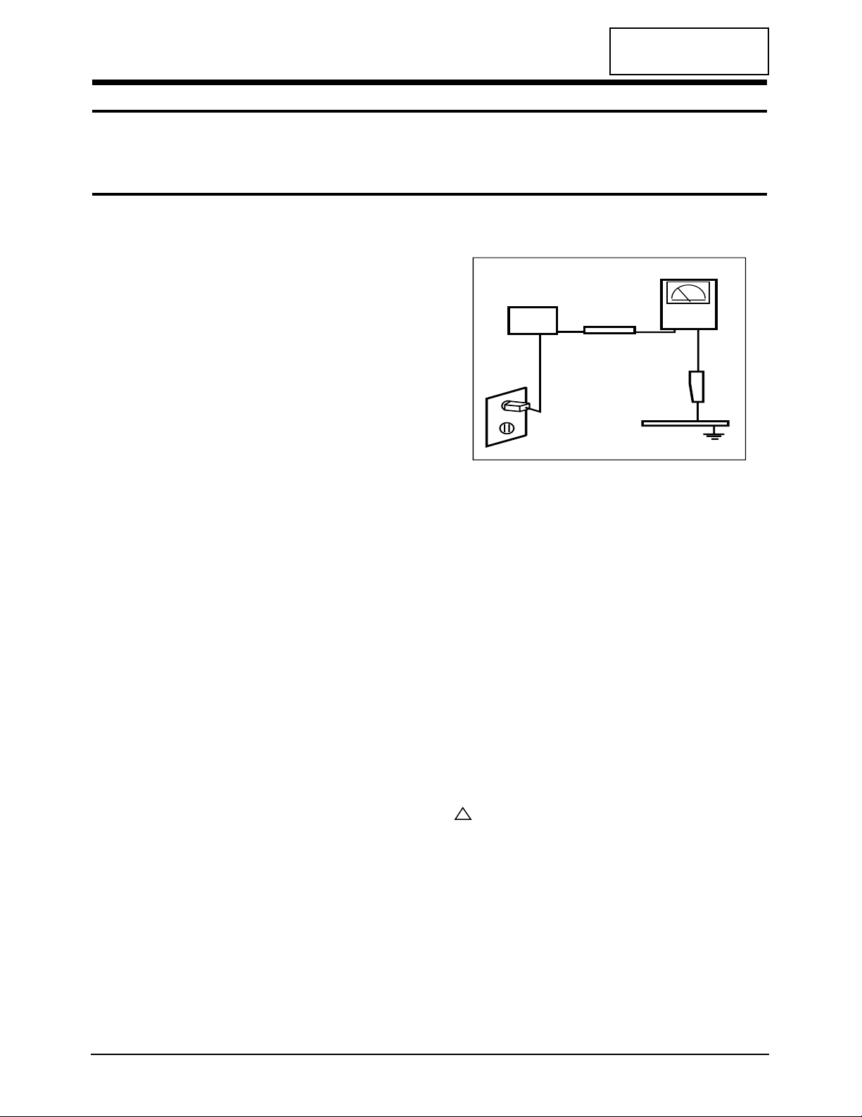
3. Leakage Current Hot Check (Figure 1-1):
WARNING: Do not use an isolation transformer during
this test.
Use a leakage current tester or a metering system
that complies with American National Standards
Institute (ANSI C101.1, Leakage Current for
Appliances), and Underwriters Laboratories (UL
Publication UL1410, 59.7).
Figure 1-1. Leakage Current Test Circuit
4. With the unit completely reassembled, plug the AC
line cord directly into a 120V AC outlet. With the
unit’s AC switch first in the ON position and then
OFF, measure the current between a known earth
ground (metal water pipe, conduit, etc.) and all
exposed metal parts, including: metal cabinets,
screwheads and control shafts. The current
measured should not exceed 0.5 milliamp. Reverse
the power-plug prongs in the AC outlet and repeat
the test.
1-1-4 Product Safety Notices
Some electrical and mechanical parts have special
safety-related characteristics which are often not
evident from visual inspection. The protection they give
may not be obtained by replacing them with
components rated for higher voltage, wattage, etc. Parts
that have special safety characteristics are identified by
on schematics and parts lists. A substitute
replacement that does not have the same safety
characteristics as the recommended replacement part
might create shock, fire and / or other hazards. Product
safety is under review continuously and new
instructions are issued whenever appropriate.
LTM1525/LT15S13C 1-1
CONFIDENTIAL
1 Precautions
Follow these safety, servicing and ESD precautions to prevent damage and to protect against potential hazards such as
electrical shock.
1-1 Safety Precautions
DEVICE
UNDER
TEST
TEST ALL
EXPOSED METAL
SURFACES
(READING SHOULD
NOT BE ABOVE 0.5mA)
LEAKAGE
CURRENT
TESTER
2-WIRE CORD
ALSO TEST WITH
PLUG REVERSED
(USING AC ADAPTER
PLUG AS REQUIRED)
EARTH
GROUND
!

1-2-1 General Servicing Precautions
1. Always unplug the unit’s AC power cord from the
AC power source and disconnect the DC Power
Jack before attempting to:
(a) remove or reinstall any component or assembly,
(b) disconnect PCB plugs or connectors, (c) connect
a test component in parallel with an electrolytic
capacitor.
2. Some components are raised above the printed
circuit board for safety. An insulation tube or tape
is sometimes used. The internal wiring is
sometimes clamped to prevent contact with
thermally hot components. Reinstall all such
elements to their original position.
3. After servicing, always check that the screws,
components and wiring have been correctly
reinstalled. Make sure that the area around the
serviced part has not been damaged.
1. Immediately before handling any semiconductor
components or assemblies, drain the electrostatic
charge from your body by touching a known earth
ground. Alternatively, wear a discharging wriststrap device. To avoid a shock hazard, be sure to
remove the wrist strap before applying power to
the monitor.
2. After removing an ESD-equipped assembly, place it
on a conductive surface such as aluminum foil to
prevent accumulation of an electrostatic charge.
3. Do not use freon-propelled chemicals. These can
generate electrical charges sufficient to damage
ESDs.
4. Use only a grounded-tip soldering iron to solder or
desolder ESDs.
5. Use only an anti-static solder removal device. Some
solder removal devices not classified as “anti-static”
can generate electrical charges sufficient to damage
ESDs.
4. Check the insulation between the blades of the AC
plug and accessible conductive parts (examples:
metal panels, input terminals and earphone jacks).
5. Insulation Checking Procedure: Disconnect the
power cord from the AC source and turn the power
switch ON. Connect an insulation resistance meter
(500 V) to the blades of the AC plug.
The insulation resistance between each blade of the
AC plug and accessible conductive parts (see
above) should be greater than 1 megohm.
6. Always connect a test instrument’s ground lead to
the instrument chassis ground before connecting
the positive lead; always remove the instrument’s
ground lead last.
6. Do not remove a replacement ESD from its
protective package until you are ready to install it.
Most replacement ESDs are packaged with leads
that are electrically shorted together by conductive
foam, aluminum foil or other conductive materials.
7. Immediately before removing the protective
material from the leads of a replacement ESD,
touch the protective material to the chassis or
circuit assembly into which the device will be
installed.
Caution: Be sure no power is applied to the
chassis or circuit and observe all
other safety precautions.
8. Minimize body motions when handling
unpackaged replacement ESDs. Motions such as
brushing clothes together, or lifting your foot from
a carpeted floor can generate enough static
electricity to damage an ESD.
1 Precautions
1-2 LTM1525/LT15S13C
CONFIDENTIAL
1-3 Electrostatically Sensitive Devices (ESD) Precautions
Some semiconductor (solid state) devices can be easily damaged by static electricity. Such components are commonly
called Electrostatically Sensitive Devices (ESD). Examples of typical ESD devices are integrated circuits and some fieldeffect transistors. The following techniques will reduce the incidence of component damage caused by static electricity.
1-2 Servicing Precautions
WARNING: An electrolytic capacitor installed with the wrong polarity might explode.
Caution: Before servicing units covered by this service manual, read and follow the Safety Precautions
section of this manual.
Note: If unforeseen circumstances create conflict between the following servicing precautions and any of the
safety precautions, always follow the safety precautions.
CONFIDENTIAL
2 Product Specifications
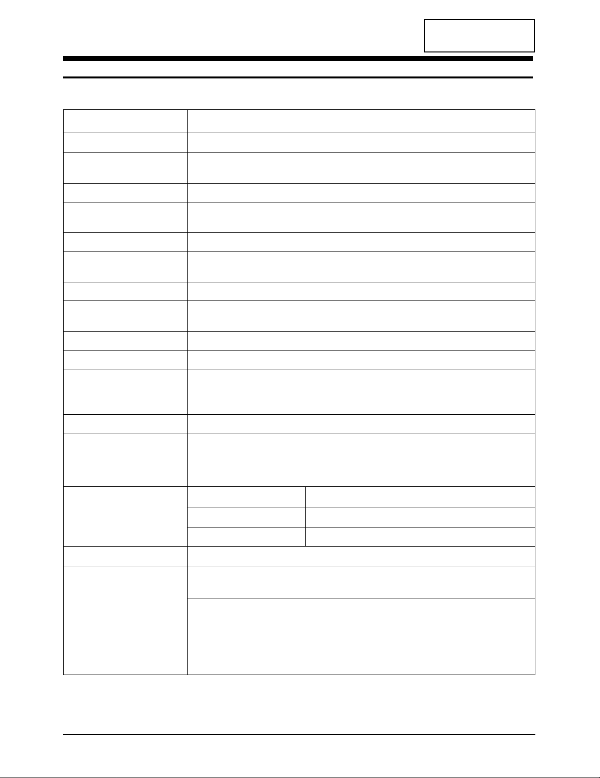
2-1 Specifications
LCD Panel TFT-LCD panel, RGB vertical stripe, normaly
white, 15-Inch viewable, 0.297 mm pixel pitch
Scanning Frequency Horizontal : 30 kHz ~ 61 kHz (Automatic)
Vertical : 56 Hz ~ 75 Hz (Automatic)
Display Colors 16.7 Million colors
Maximum Resolution Horizontal : 1024 Pixels
Vertical : 768 Pixels
Input Video Signal Analog 0.7 Vp-p ± 5% positive at 75 Ω, internally terminated
Input Sync Signal Type : Seperate H/V
Level : TTL level
Maximum Pixel Clock rate 80 MHz
Active Display
Horizontal/Vertical
AC power voltage & Frequency
AC 90 ~ 264 Volts, 60 / 50 Hz ± 3 Hz
Power Consumption 45 W (Max)
Dimensions
Unit (W x D x H) 13.6 x 6.7 x 14.2 Inches (346.0 x 169.0 x 361.5 mm)
Carton (W x D x H) 16.8 x 4.5 x 21.0 Inches (427 x 114 x 535 mm)
Weight 3.2 Kg / 7.05 Ibs (With Stand)
Environmental Considerations Operating Temperature : 50 °F ~ 104 °F (10 °C ~ 40 °C)
Humidity : 10 % ~ 80 %
Storage Temperature : -4 °F ~ 113 °F (-20 °C ~ 45 °C)
Humidity : 5 % ~ 95 %
TV System
Antena Input 75Ω, Coaxial Cable
– MAX Internal speaker Output : Right => 3W
Left => 3W
Sound Characteristic
– BASS Control Range : -12 dB~ + 12 dB
– TREBLE Control Range : -12 dB~ + 12 dB
– Headphone Out: 5mW max (400m Vrms)
– Output Frequency : RF => 80 Hz ~ 15 kHz
A/V => 80 Hz ~ 15 kHz
LTM1525/LT15S13C 2-1
Item
Description
304.1 mm / 228.1 mm
Tunning Frequency Synthesize
System NTSC-M
Sound STEREO
2 Product Specifications
2-2 LTM1525/LT15S13C
CONFIDENTIAL
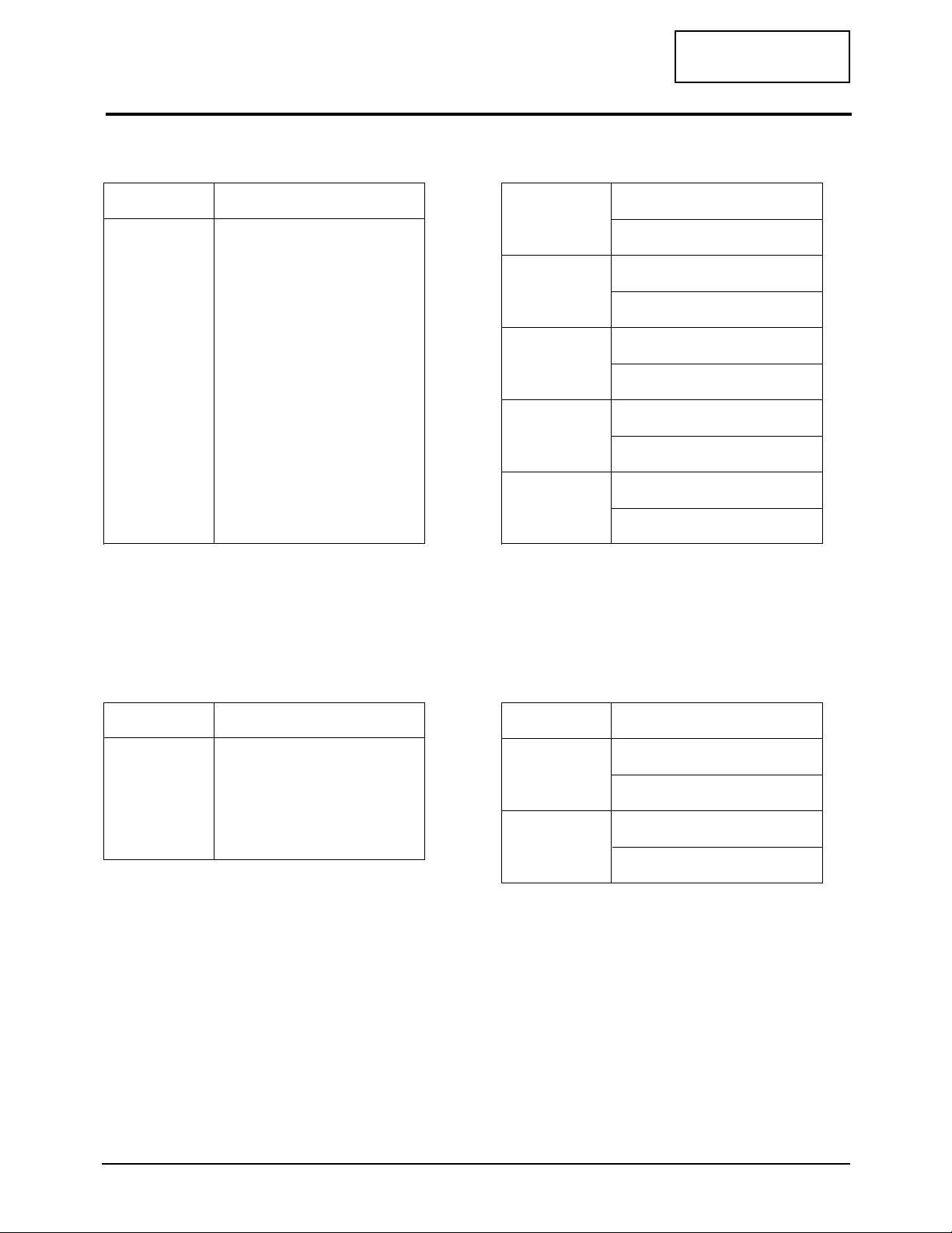
2-2 Pin Assignments
Pin
Separate
1
2
3
4
5
6
7
8
9
10
11
12
13
14
15
Red
Green
Blue
GND
GND (DDC Return)
GND-Red
GND-Green
GND-Blue
No Connection
GND-Sync./Self Test
GND
DDC Data
H-Sync.
V-Sync.
DDC Clock
Pin
Separate
1
2
3
4
5
GND
Y
C
GND
GND
RCA Green
RCA Blue
RCA Red
RCA White
RCA Red
Y
GND
Pb (Cb)
GND
Pr (Cr)
GND
Audio L
GND
Audio R
GND
2-2-1 D-SUB
2-2-3 S-Video
2-2-2 DVD, DTV
RCA White
RCA Red
CVBS
Audio L
GND
Audio R
GND
2-2-4 A/V
RCA Yellow
2 Product Specifications
LTM1525/LT15S13C 2-3
CONFIDENTIAL
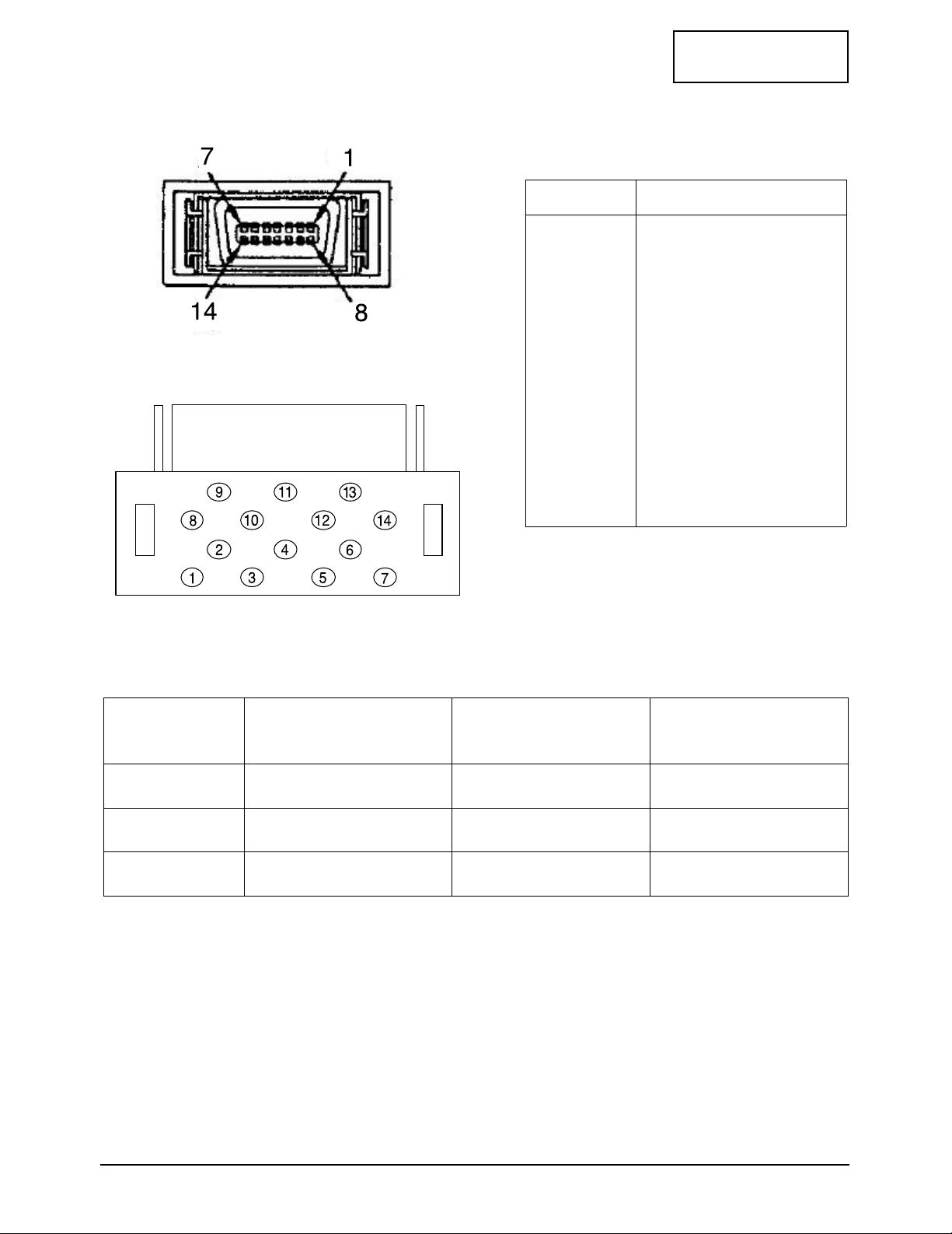
2-2-5 D4 CONNECTOR
Pin
Separate
1
2
3
4
5
6
7
8
9
10
11
12
13
14
Y
Y_GND
Pb
Pb_GNd
Pr
Pr_GNd
Preliminary Line1
Line1
Line5
Preliminary Line2
Line3
Switch GND
Prlimainary Line3
Switch
5V
2.2V
0V
1080
720
480
60p
-
60i
16 : 9
letter box
4 : 3
Line 1
(Resolution)
Line2
(i/p)
Line3
(Aspect)
2 Product Specifications
2-4 LTM1525/LT15S13C
CONFIDENTIAL
2 Product Specifications
LTM1525/LT15S13C 2-5
CONFIDENTIAL
2 Product Specifications
2-6 LTM1525/LT15S13C
CONFIDENTIAL
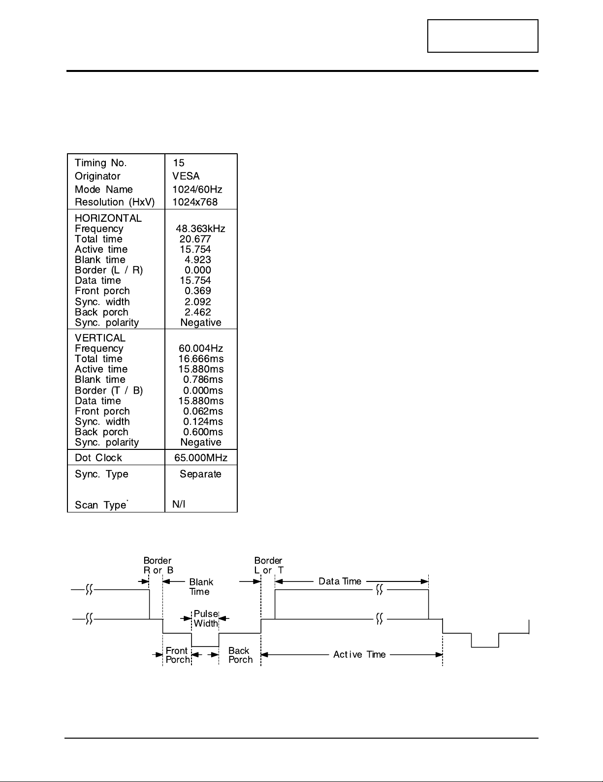
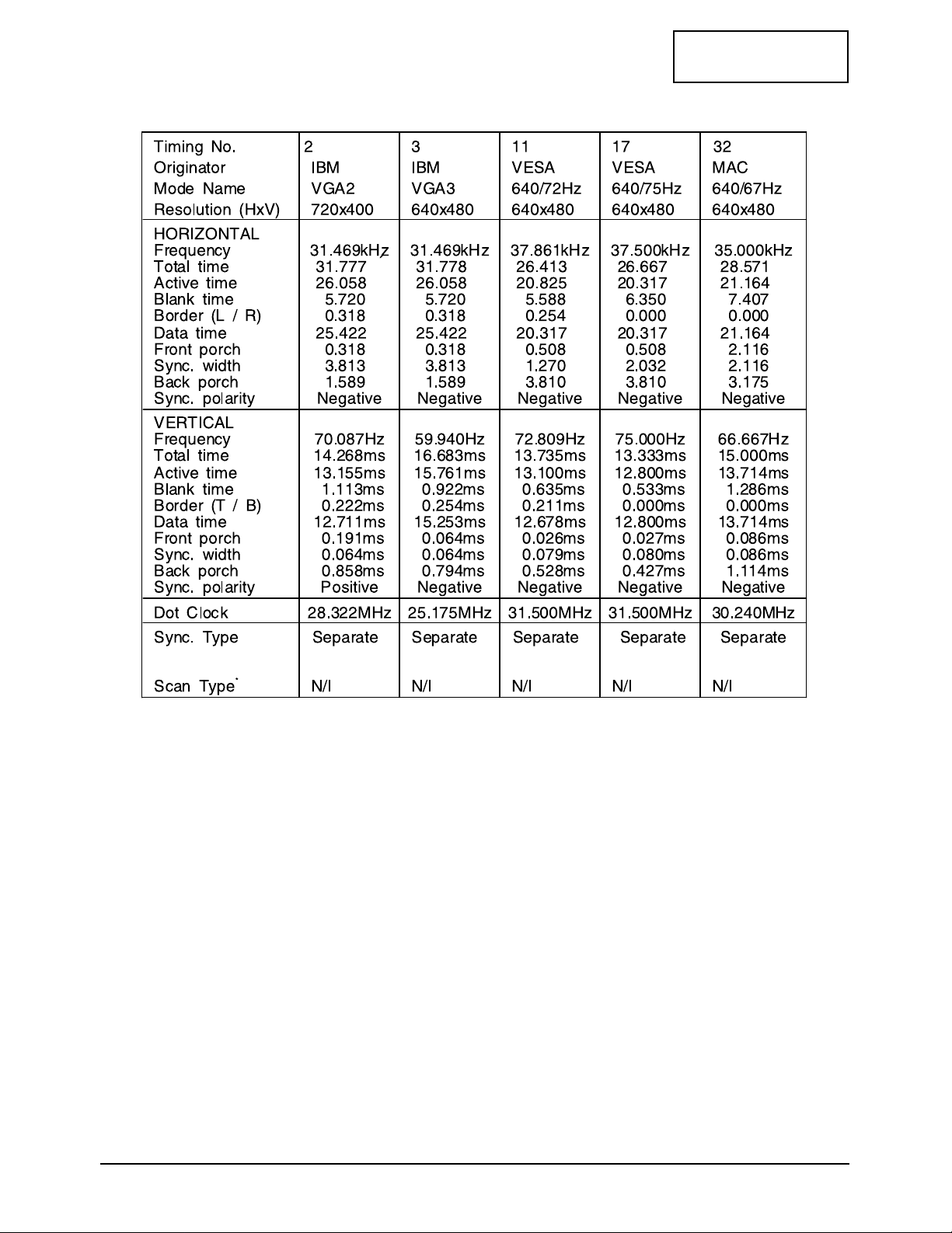
2-3 Timing Chart
This section of the service manual describes the timing that the computer industry recognizes as standard
for computer-generated video signals.
µs
µs
µs
µs
µs
µs
µs
µs
2-3-1 LCD Panel Mode : 1 mode
2 Product Specifications
LTM1525/LT15S13C 2-7
CONFIDENTIAL
2-3-2 Supported Modes (1)
µs
µs
µs
µs
µs
µs
µs
µs
µs
µs
µs
µs
µs
µs
µs
µs
µs
µs
µs
µs
µs
µs
µs
µs
µs
µs
µs
µs
µs
µs
µs
µs
µs
µs
µs
µs
µs
µs
µs
µs
2 Product Specifications
2-8 LTM1525/LT15S13C
CONFIDENTIAL
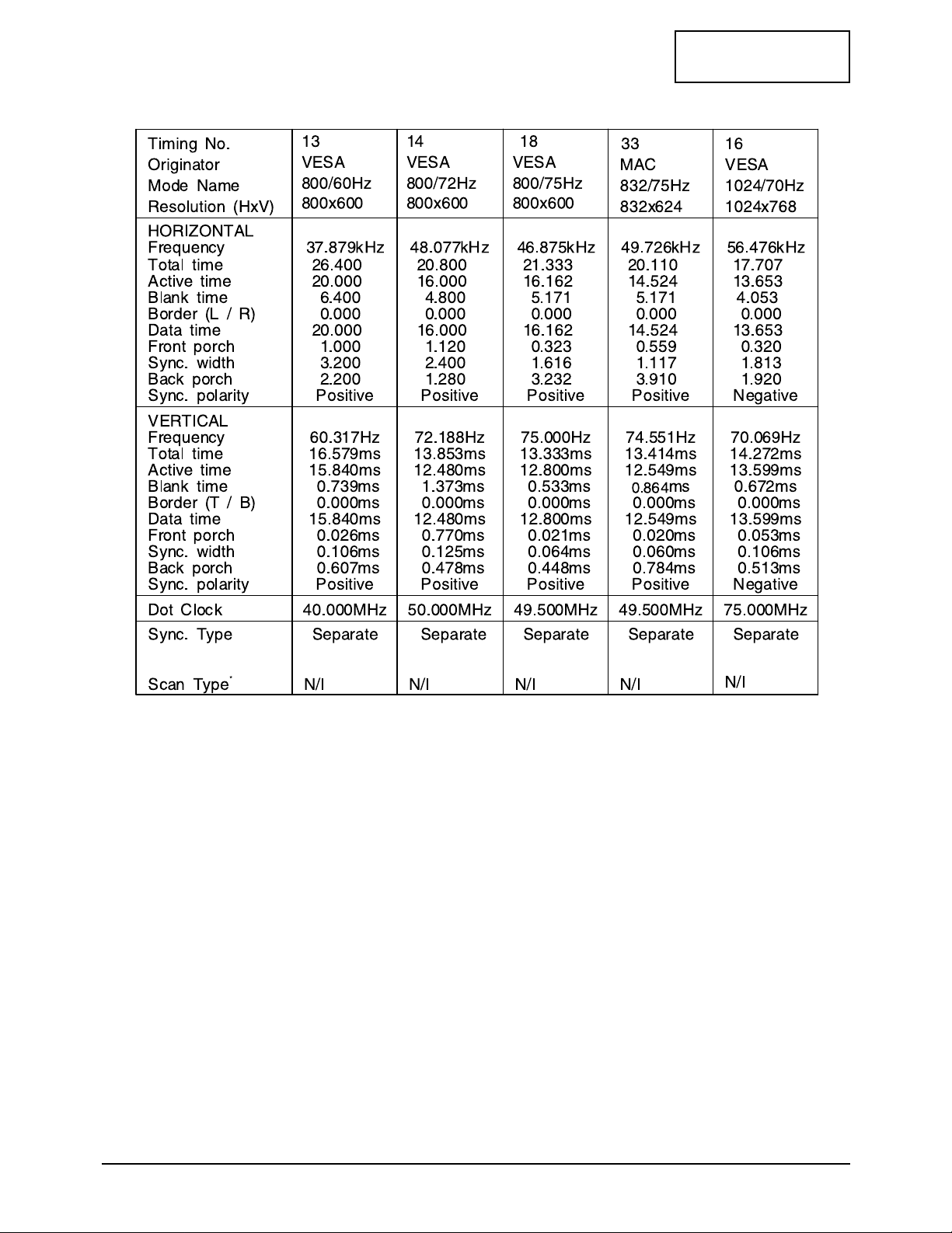
2-3-2 Supported Modes (2)
µs
µs
µs
µs
µs
µs
µs
µs
µs
µs
µs
µs
µs
µs
µs
µs
µs
µs
µs
µs
µs
µs
µs
µs
µs
µs
µs
µs
µs
µs
µs
µs
µs
µs
µs
µs
µs
µs
µs
µs
2 Product Specifications
LTM1525/LT15S13C 2-9
CONFIDENTIAL
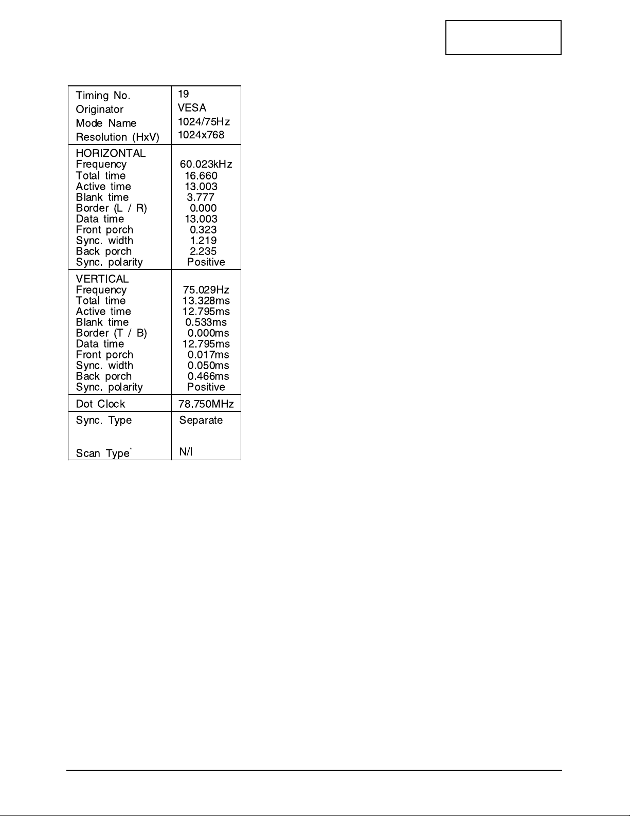
2-3-2 Supported Modes (3)
s
s
s
s
s
s
s
s

Memo
2 Product Specifications
2-10 LTM1525/LT15S13C
CONFIDENTIAL
LTM1525/LT15S13C 3-1
CONFIDENTIAL
3 Disassembly and Reassembly
This section of the service manual describes the disassembly and reassembly procedures for the
LTM1525/LT15S13C monitor.
WARNING: This monitor contains electrostatically sensitive devices. Use caution when handling
these components.
3-1 Disassembly
Cautions:1. Disconnect the monitor from the power source before disassembly.
2. Follow these directions carefully; never use metal instruments to pry apart the cabinet.
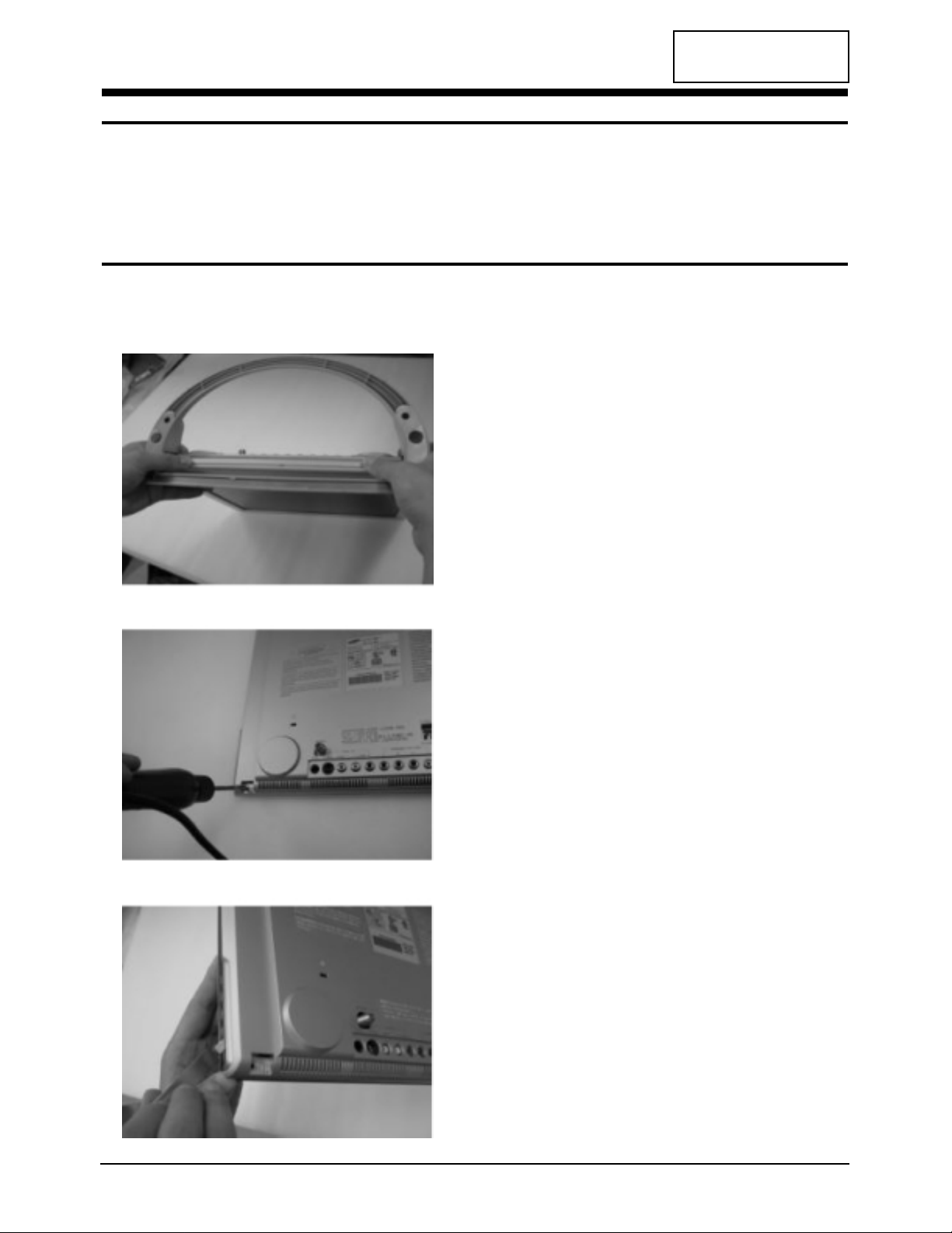
1. The stand is held into the bottom of the unit
by a pair of retaining clips (near the left and
right hinges) To remove the stand, simply pull
it away from the unit and the retaining clips
will release automatically.
2. Remove the two phillips screws (left and
right).
3. Separate the case halves (front/back) starting
at the bottom/edges.

CONFIDENTIAL
3 Disassembly and Reassembly
3-2 LTM1525/LT15S13C
3-2 Reassembly
Reassembly procedures are in the reverse order of Disassembly procedures.

CONFIDENTIAL
LTM1525/LT15S13C 4-1
4 Alignments and Adjustments
4-1 General Alignment Instuction
1. Usually, a color TV-VCR needs only slight touch-up adjustment upon installation.
Check the basic characteristics such as height, horizontal and vertical sync.
2. Use the specified test equipment or its equivalent.
3. Correct impedance matching is essential.
4. Avoid overload. Excessive signal from a sweep generator might overload the front-end
of the TV. When inserting signal markers,do not allow the marker generator to distort
test result.
5. Connect the TV only to an DC power source with voltage and frequency as specified on
the backcover nameplate.
6. Do not attempt to connect or disconnect any wire while the TV is turned on. Make sure
that the power cord is disconnected before replacing any parts.
7. To protect aganist shock hazard,use an isolation transform.
4 Alignments and Adjustments
4-2 LTM1525/LT15S13C
CONFIDENTIAL
RF
127 75
127 75
130 82
218 DA
195 C3
248 F8
208 DO
160 B7
160 68
120 70
133 85
OE
06/24 T-MB01-102
06/24 T-MB01-102
OE
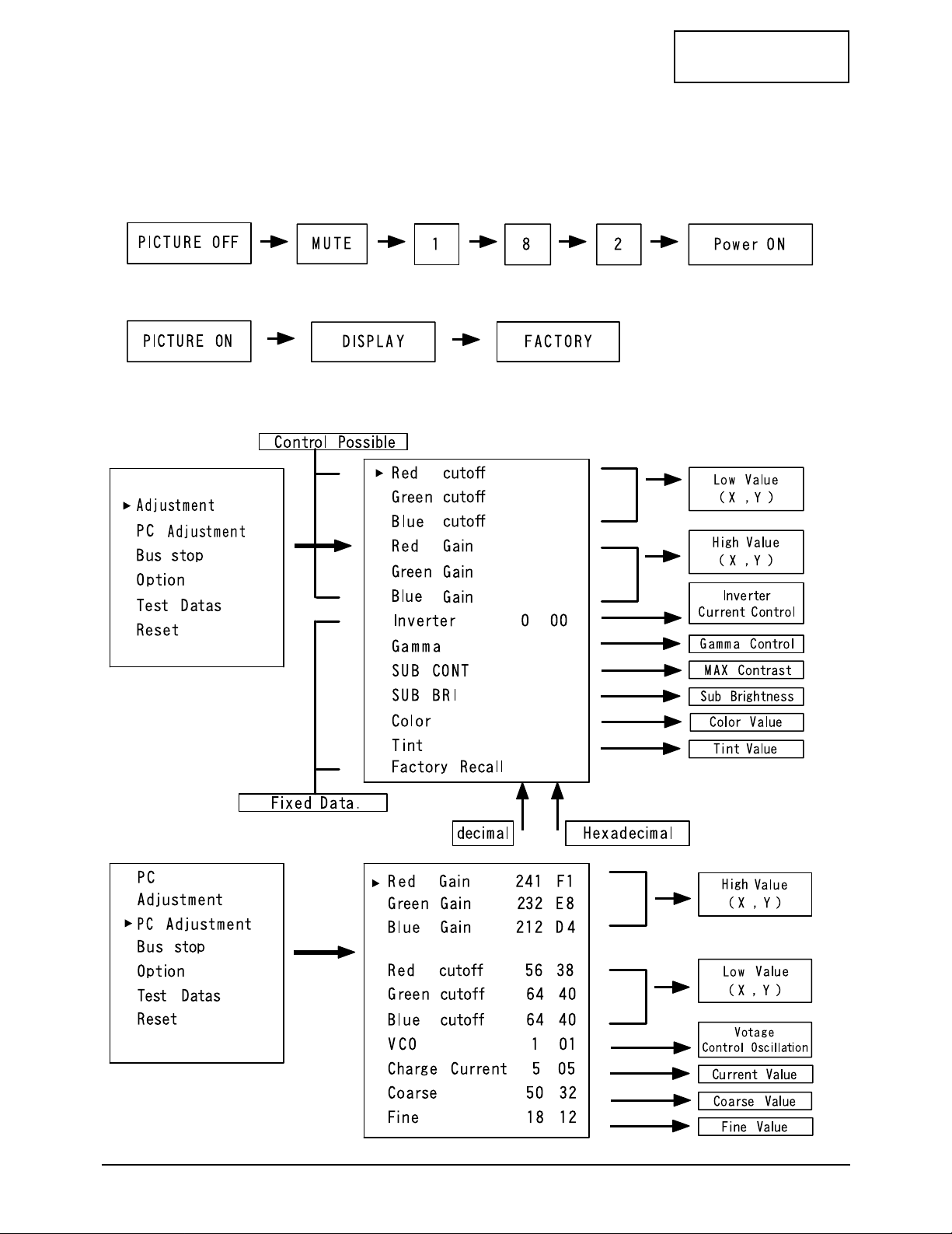
4-2 Factory Mode Adjustments
4-2-1 Entering Factory Mode
1. To enter “Service Mode” Press the remote -control keys in this sequence :
- If you do not have Factory remote - control
- If you have Factory remote - control
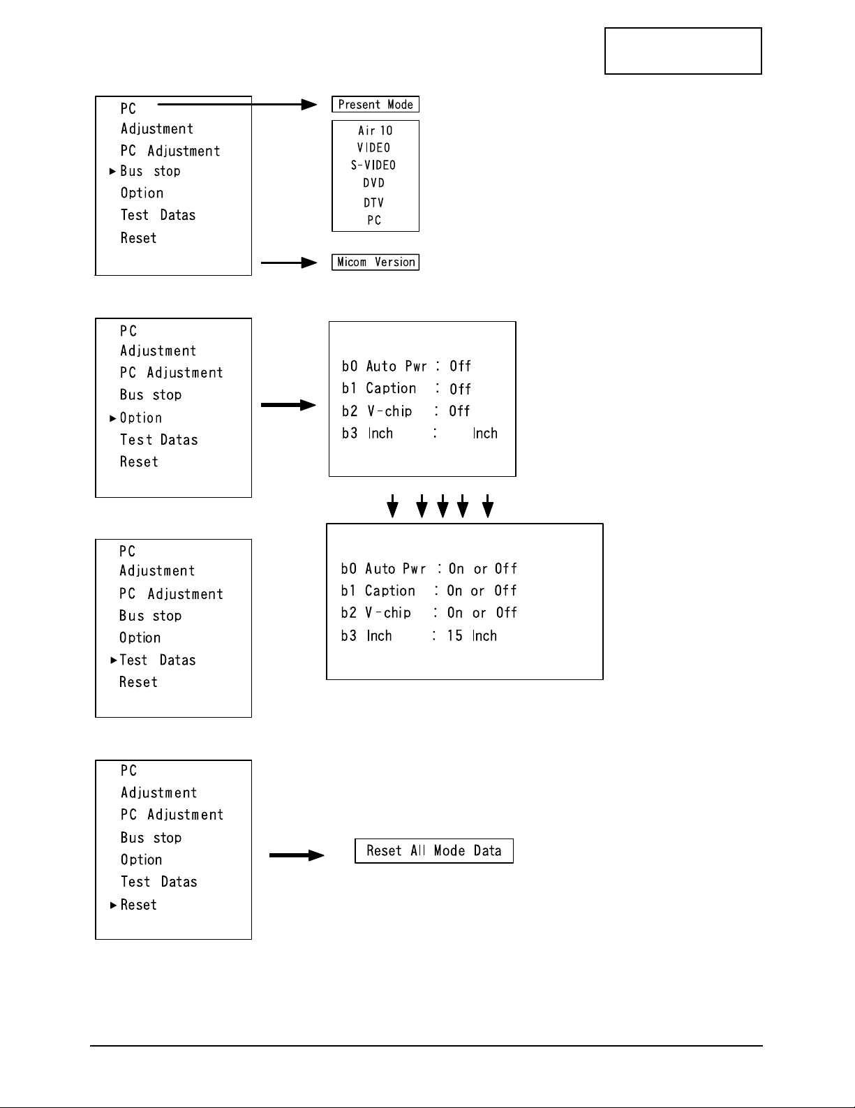
4-2-2 Factory Mode Tree (U.S. Only)
4 Alignments and Adjustments
LTM1525/LT15S13C 4-3
CONFIDENTIAL
OE
06/24 T-MB01-102
OE
06/24 T-MB01-102
OE
06/24 T-MB01-102
15
OE
06/24 T-MB01-102
4 Alignments and Adjustments
4-4 LTM1525/LT15S13C
CONFIDENTIAL
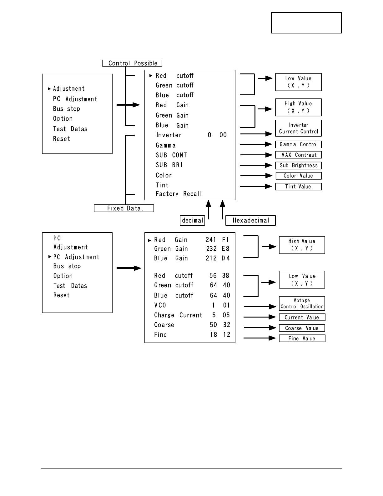
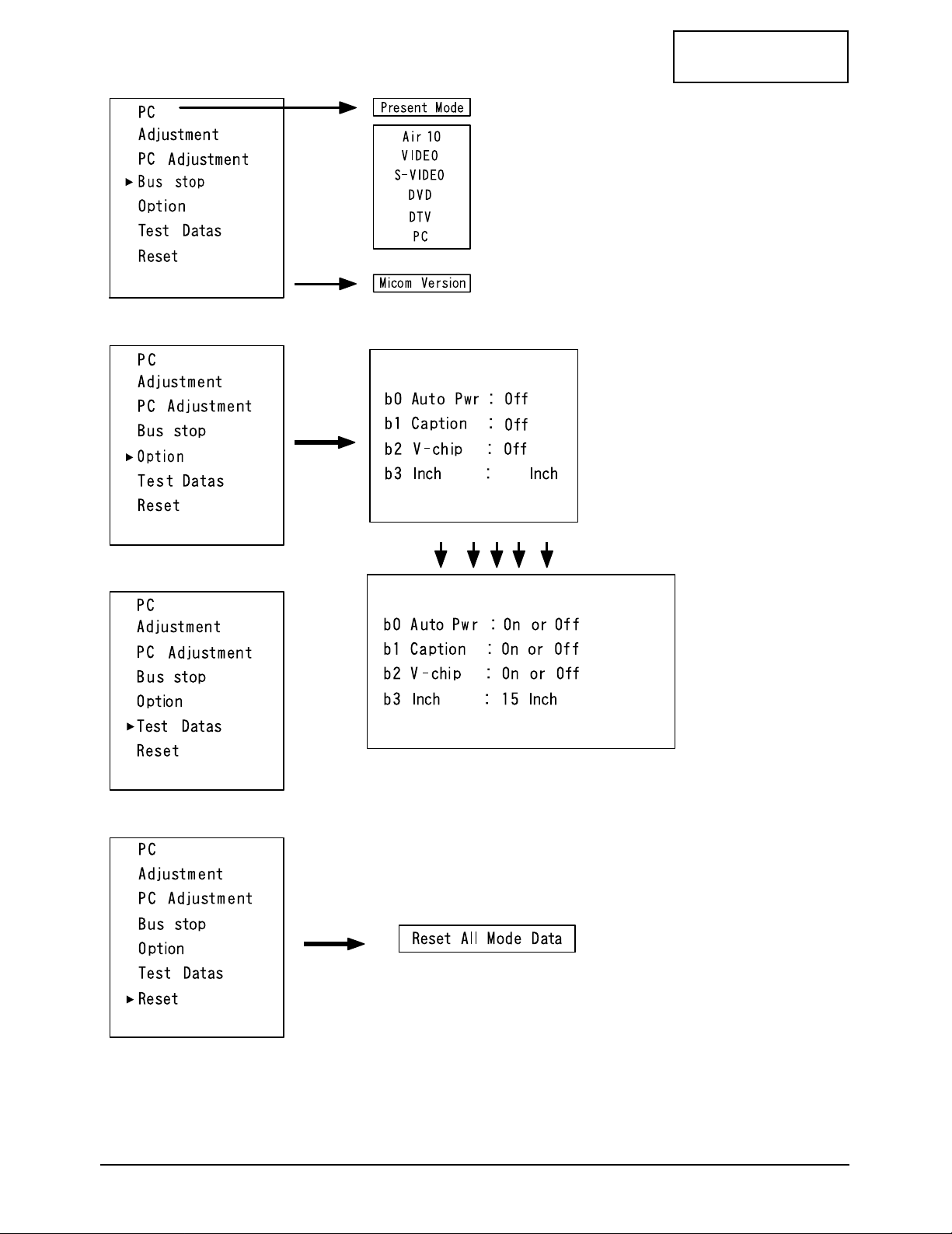
4-2-3 Factory Mode Tree (Japan Only)
RF
O4
06/24 T-MB03-102
127 75
127 75
130 82
218 DA
195 C3
248 F8
208 DO
160 B7
160 68
120 70
133 85
O4
06/24 T-MB03-102
4 Alignments and Adjustments
LTM1525/LT15S13C 4-5
CONFIDENTIAL
04
06/24 T-MB03-102
04
06/24 T-MB03-102
04
06/24 T-MB03-102
15
04
06/24 T-MB03-102

Memo
4 Alignments and Adjustments
4-6 LTM1525/LT15S13C
CONFIDENTIAL
CONFIDENTIAL
LTM1525/LT15S13C 5-1
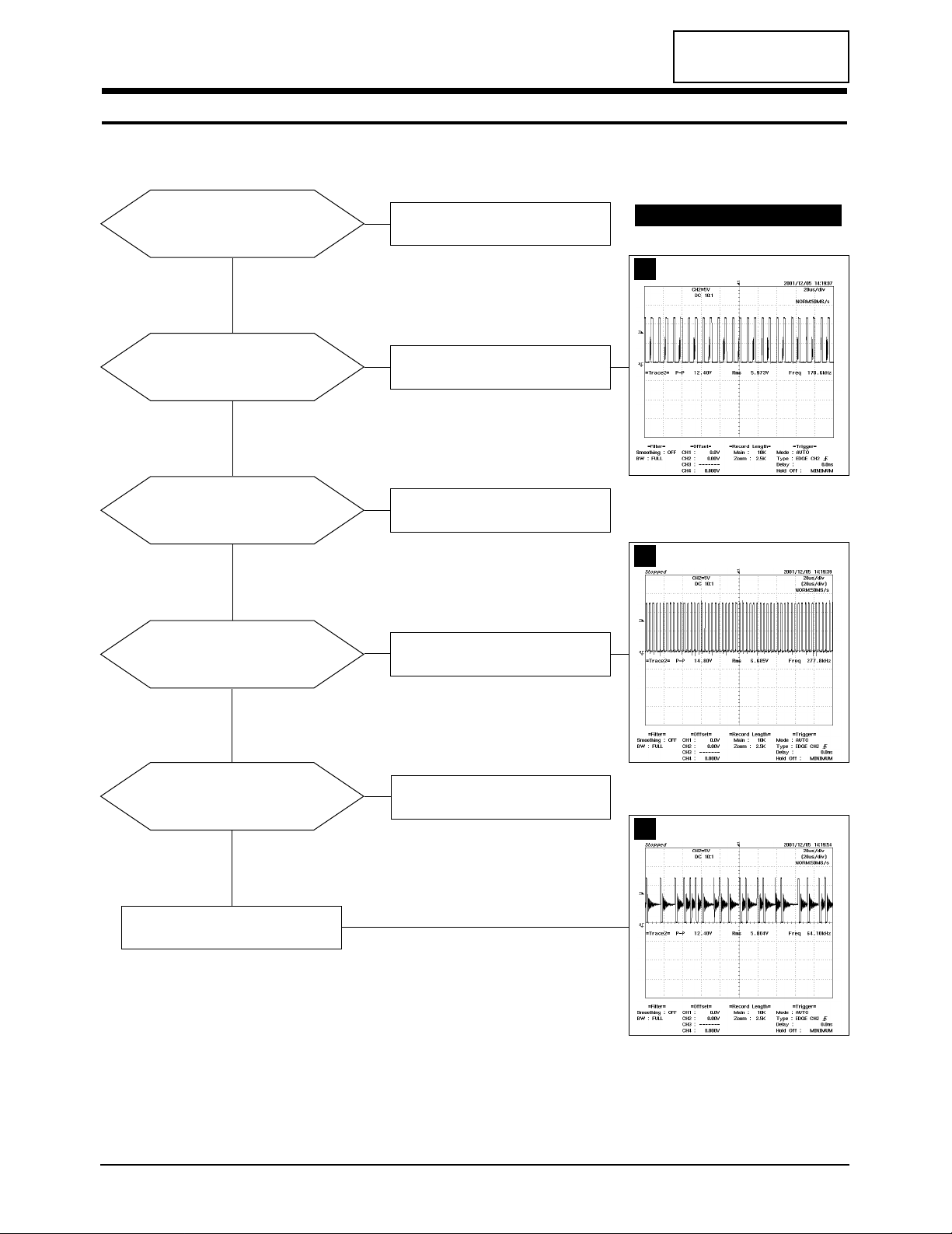
5 Troubleshooting
5-1 No Power
Does proper DC 14V appear at DC
jack connected to CN801?
Check SMPS PCB and Adapter.
Yes
No
No
No
No
No
Does proper DC 3.3V_A
appear at FT852?
Check IC811.
Check IC812.
Yes
Does proper DC 2.5V_A
appear at Pin 3 of IC802?
Check IC802.
Yes
Does proper DC 3.3V_B
appear at T807?
Check IC805.
Yes
Yes
Does proper DC 2.5V_B
appear at Pin 4 of IC806?
Check IC806.
WAVEFORMS
IC811 #2
IC805 #1
IC812 #2
1
2
3
CONFIDENTIAL
5 Troubleshooting
5-2 LTM1525/LT15S13C
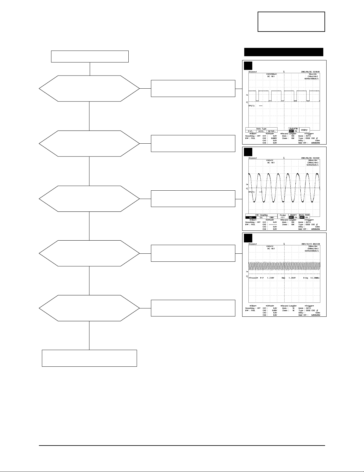
5-2 No Video (PC Signal)
Power indicator is green.
Does the signal appear
at C491, C489, C488
of R, G, B input?
Check CN401 and cable.
Yes
No
No
No
No
No
Yes
Does the clock pulse
appear at output of
T201, T202, T203 ~ RA356?
Check related circuit of IC350.
Yes
Does the clock pulse
appear at R354?
Check R354 and related
circuit of R354.
Yes
Does the clock pulse
appear at X201?
Check X201 and related
circuit of X201.
Yes
Does the clock pulse appear at
output of RA301~RA306?
Replace RA301 ~ RA306, IC300.
Yes
Replace LCD Panel.
WAVEFORMS
C491
4
R354
5
X201
6
CONFIDENTIAL
5 Troubleshooting
LTM1525/LT15S13C 5-3
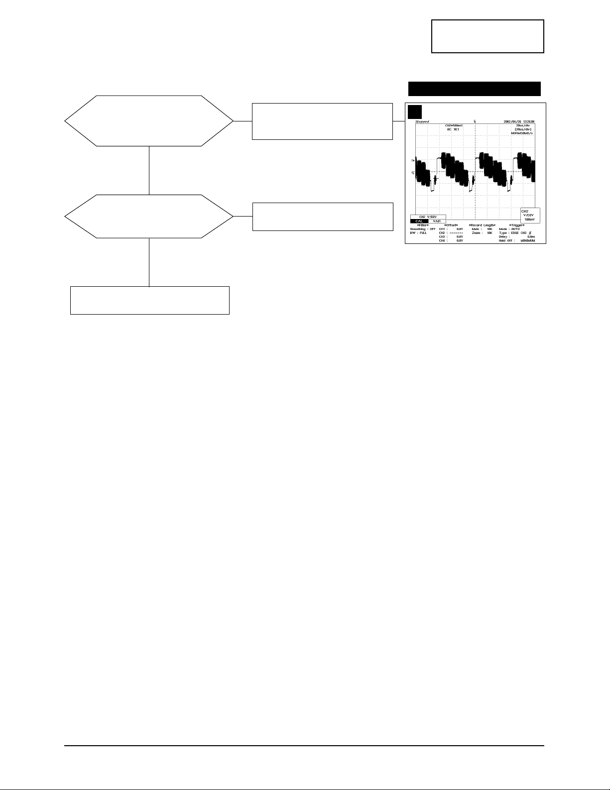
5-3 No Picture (TV, Video, S-Video, DVD, DTV)
Check Pin 185, 196 (S-Video)
and Pin 184 (VCR) and Pin 183
(RF-CVBS) of IC200 (DPTV_3D)?
Check Pin 16 of CN828
at TV color bar.
Yes
Check analog RGB out Pin 27, 28,
29 and check 3.3V_RA Pin 199,
181, 192, 194, 205 at IC200?
Check the IC813 and IC200.
Yes
Check the IC200, C285, C241 and C249.
WAVEFORMS
CN828 #16
7
No
No
CONFIDENTIAL
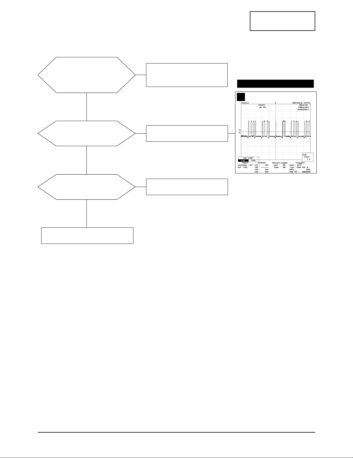
5 Troubleshooting
5-4 LTM1525/LT15S13C
Does the signal appear at
Pin 67 (Tuner sound signal) and
Pin 47, 48 (PC sound) and Pin 56, 57
(VCR sound) and Pin 50, 51 (DVD)
of IC 919 (MSP3421)?
Check the CN401(PC Sound) and the
SK3(VCR Sound) and the SK2
(DVD/DTV Sound) the CN828(Tuner).
Yes
Does the signal appear at Pin 27,
28 of IC919 (MSP3421)?
Check the Pin 3 of IC919 and
related circuit of IC919.
Yes
Does the signal appear
at R505, R506?
Check the IC503 (Audio amp) and
related circuit of IC503.
Yes
Replace the speaker.
5-4 No Sound
WAVEFORMS
IC919 #3
8
No
No
No
CONFIDENTIAL
LTM1525/LT15S13C 6-1
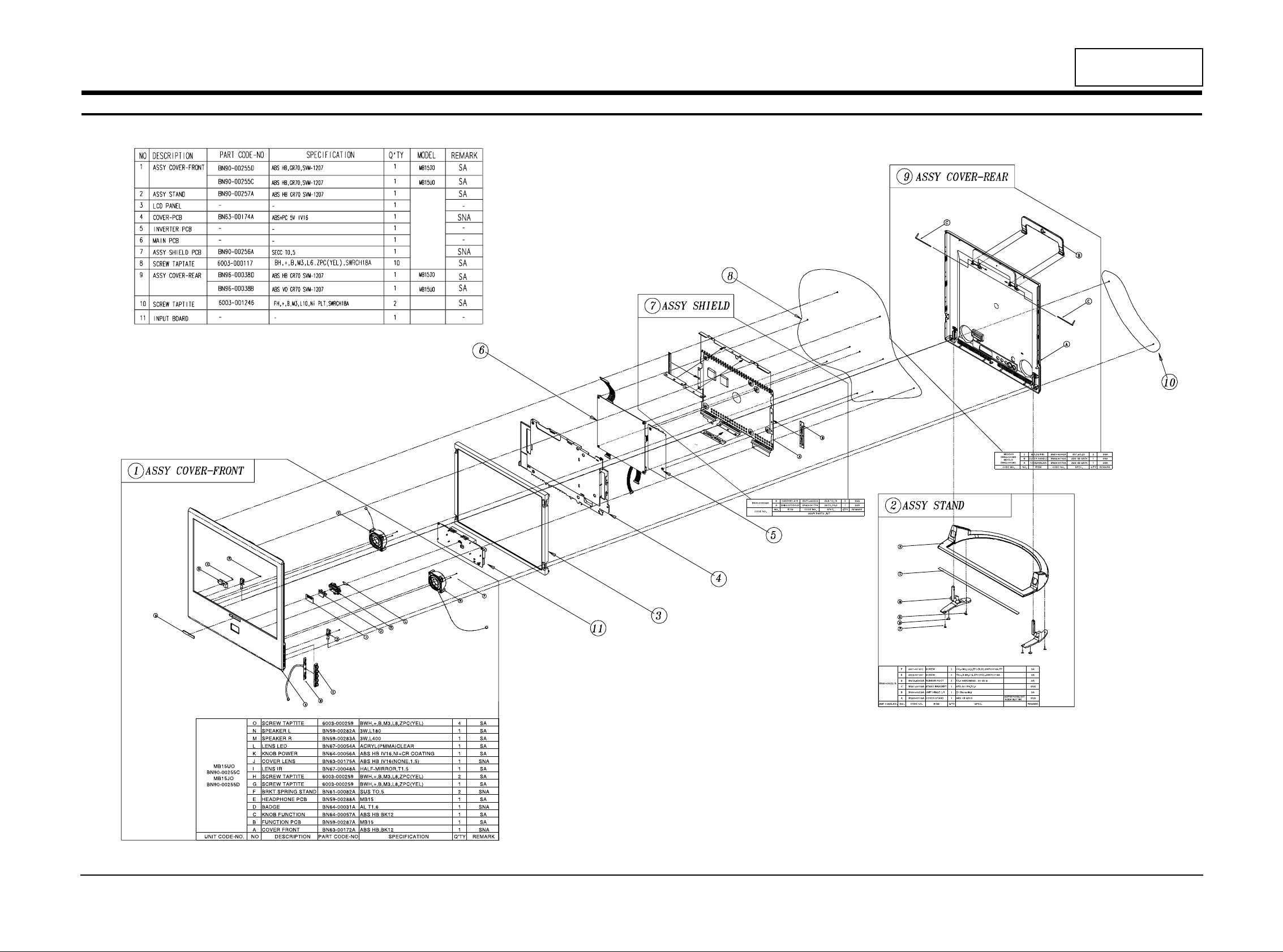
6 Exploded View and Parts List

Memo
6 Exploded View & Parts List
6-2 LTM1525/LT15S13C
CONFIDENTIAL

BN90-00297A - ASSYCOVERREAR MB15UO SNA
6003-001246 C/F+C/R SCREW-TAPTITE FH,+,B,M3,L10,NIPLT,SWRCH18A SNA
BN96-00038B CIS ASSYCOVERP-REAR MB15UO,USA,ABSHB,SVM-1207
BN61-00092A CIS BRACKET-PIN RB15,CU+ZN,T0.23,35MM SNA
BN63-00173A CIS COVER-REAR RB15,ABS,-,-,-,HB,-,BK08,SILVERSPRAY SNA
BN63-00199A CIS COVER-HANDLE RB15,ABS,HB,BK08,HB,1.5 SNA
BN90-00318A - ASSYSTAND MB15NO SNA
BN90-00257A CIS ASSYSTAND RB15,-,ABDHB,-,-,-,-,6001-001612 CIS SCREW-MACHINE CH,+,M2,L3.5,ZPC(BLK),SWRCH18A,FP,6003-001347 CIS SCREW-TAPTITE FH,+,B,M4,L16,ZPC(YEL),SWRCH18A,- SNA
BN61-00158A CIS BRACKET-STAND MINERVA,STS420J2,T2.0 SNA
BN63-00176A CIS COVER-STAND RB15,ABS,-,-,-,HB,-,BK08,HB,1.5 SNA
BN73-60002A CIS RUBBER-FOOT CY15PO,SPONGE,-,-,-,BL,-,-,-,- SNA
BN90-00258A CIS ASSYHINGE RB15,-,AL,-,-,-,-,DIE-CASTING SNA
BN90-00341A - ASSYCOVERFRONT MB15UO SNA
BN90-00255C CIS ASSYCOVERFRONT MB15UO,USA,ABSVO,SVM-1207
6003-000259 CIS SCREW-TAPTITE BH,+,B,M3,L8,ZPC(YEL),SWRCH18A SNA
BN59-00282A CIS SPEAKERSYSTEM MINERVA,MINERVA-R,3W,46X46X20,3W4OHM,WIRE:395MM
BN59-00283A CIS SPEAKERSYSTEM MINERVA,MINERVA-L,3W,46X46X20,3W4OHM,WIRE:110MM
BN59-00287A CIS BOARD-FUNCTIONASS'Y MB15UO,CT5000-0610,FUNCTIONASS'Y SNA
BN59-00288A CIS BOARD-PHONEJACKASS'Y MB15UO,CT5000-0620,PHONE-JACKASS'Y SNA
BN61-00082A CIS BRACKET-SPRING-STAND RB15,SUS,T0.5,-,-,-,- SNA
BN63-00172A CIS COVER-FRONT RB15,ABS,-,-,-,HB,-,BK08,SILVERSPRAY SNA
BN63-00175A CIS COVER-LENS RB15,ABS,-,-,-,HB,-,IV16,NONE,1.5 SNA
BN64-00031A CIS BADGE-BRAND RB15AS,AL,T1.4,6.3,40.1,-,SILIVER,- SNA
BN64-00056A CIS KNOB-POWER RB15,PC,-,-,-,HB,CLEAR,-,NI-CR
BN64-00057A CIS KNOB-FUNCTION RB15,ABS+PC,-,-,-,HB,BK08,-,NONE,1.5
BN67-00048A CIS LENS-IR RB15,ACRYL,CLEAR,-,1.5,-,HALF-MIRROR SNA
BN67-00054A CIS LENS-LED RB15,ACRYL,CLEAR,1
BN91-00220A - ASSYLCD ES15AS SNA
BN07-00053A CIS LCD LTM150XH-L06,CZB,6BIT_FRC,331.6*254.76*12.5,16.19M,-,0.297*0.297,-,-,AMLCD/1LV
BN91-00310F CIS ASSYMISC MB15 SNA
BN44-00063A CIS ADAPTOR AD-4914N,EOS17,100-240VAC,47-63HZ,+14VDC,3.5A,-,49W,-,0TO+40C,120*63*31,SA
BN91-00394A - ASSYCHASSIS MB15NO
BN94-00309A - ASSYPCBMAIN MB15NO SNA
0201-001223 CIS ADHESIVE-TS HT-130S,RED,700+/-50,- SNA
0202-001044 CIS SOLDER-WIRE. S63S-W3.0,S63S,D3,63Sn/37Pb,- SNA
0202-001046 CIS SOLDER-WIREFLUX CF-110VH-2A,-,-,-,- SNA
0202-001222 CIS SOLDER-WIREFLUX RS-107,RS60-1.2AA,D1.2,SN60/PB40,- SNA
0204-001095 CIS THINNER #4520,-,-,- SNA
BH73-60304E CIS RUBBER-SUPPORT MO15PS,CRV0,6*6*6.4,BLACK SNA
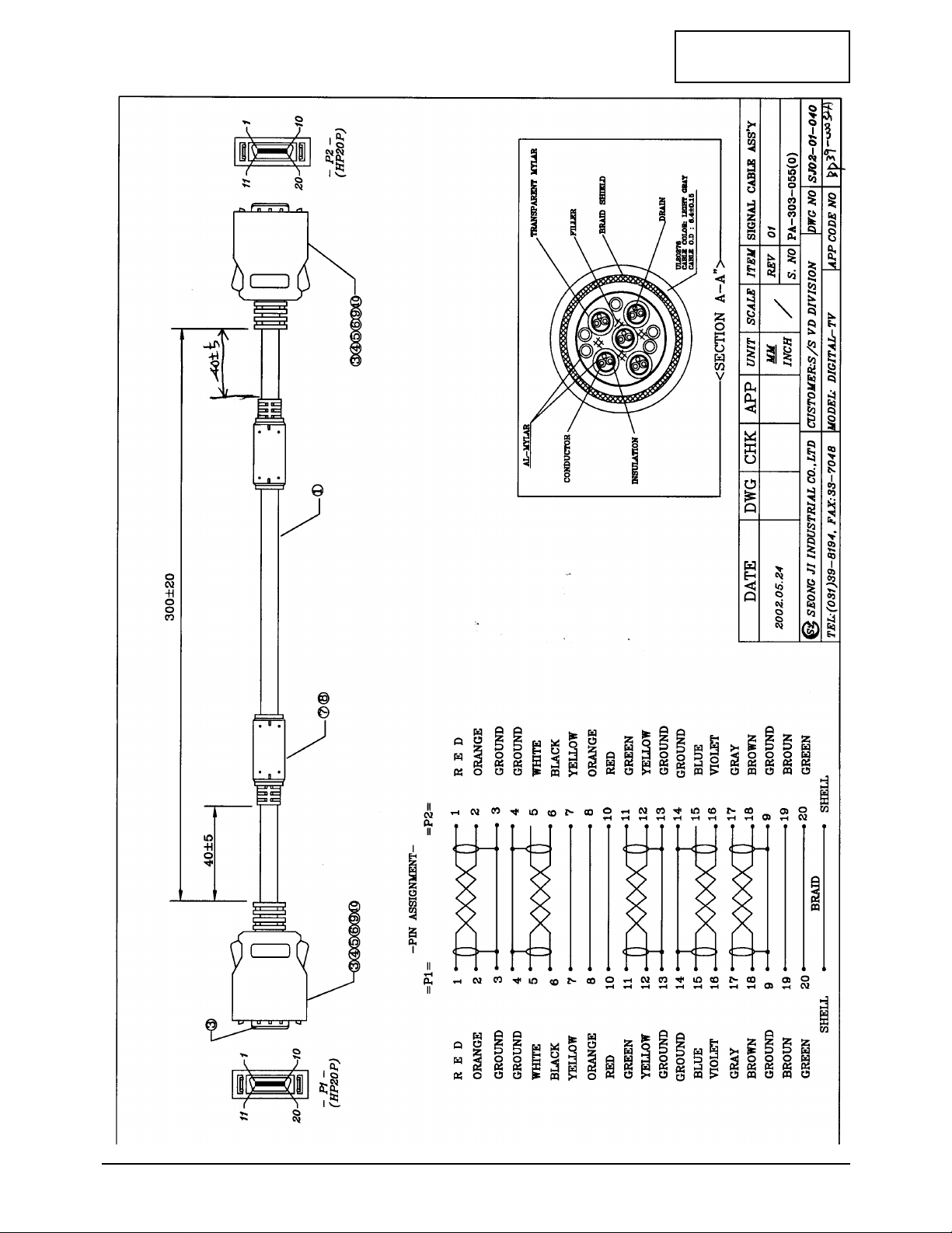
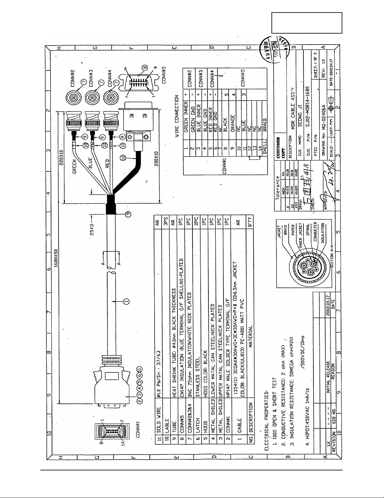
BN39-00161B CIS LEADCONNECTOR-ASSY MB15UO,UL1571#30,UL/CSA,12P,#28,12505HS-12,12505HS-12,BK,40MM,1571#30,SJ02-01-05
BN39-00272A CIS LEADCONNECTOR-ASSY MB15UO,UL1571#28,UL/CSA,20P,#28,12507HS-20,12507HS-20,BK,50MM,1571#28,SJ01-01-40
BN39-00275A CIS LEADCONNECTOR-ASSY MB15UO,UL1061#28,UL/CSA,8P,#28,12505HS-08,12505HS-08,BK,125MM,1061#28,SJ02-01-06
BN39-00287A CIS LEADCONNECTOR-ASSY MB15UO,UL1571#28,UL/CSA,21P,#28,FI-W21S,FI-W21S,BK,40MM,1571#28,SJ01-01-405(1)
BN39-00288A CIS LEADCONNECTOR-ASSY MB15UO,UL1571#28,UL/CSA,31(25)P,#28,FI-W31S,FI-W31S,BK,40MM,1571#28,SJ01-01-405(
BN44-00061B CIS INVERTER MB15UO,SIC540A,48KHZ,14VDC,3.6MARMS,6.8MARMS,48KHZ,140*65.5*7.0,4LAMP,48KHZ
BN60-00011A CIS FASTENER-PEM/NUT MINERVA,SUM24L(SN),M3,-,7.0,6.8,WHT SNA
BN63-00174A CIS COVER-PCB RB15,ABS,-,-,-,V0,-,IV16,TBBA,1.5 SNA
BN63-00345A CIS SHIELD-SUB MO15,SUS,T0.15 SNA
BN63-00413A CIS GASKET MB15KO,CONDUCTIVEFABRIC,5MM,8MM,8MM,GRAY,71TSMK8-5-8-13-D,71TSMK8-5-8-13-D SNA
BN97-00096M - ASSYMICOM MB15NO
1102-001129 IC620 IC-EPROM M27W401,512KX8BIT,PLCC,32P,11.35X13.89MM,80NS,3.3V,10%,PLASTIC,-40TO+85C,-,CMOS,
BN46-00012J CIS S/WMICOM MB15NO SNA
BN97-00100A - ASSYSMD MB15NO SNA
0202-001162 CIS SOLDER-CREAM RMA-20-21L,S63,-,SN63/PB36.6/AG0.4,FLUX9.5% SNA
0401-001056 D409 DIODE-SWITCHING MMBD4148SE,75V,200MA,SOT-23,TP
Page1

0401-001056 D410 DIODE-SWITCHING MMBD4148SE,75V,200MA,SOT-23,TP
0401-001056 D411 DIODE-SWITCHING MMBD4148SE,75V,200MA,SOT-23,TP
0401-001056 D681 DIODE-SWITCHING MMBD4148SE,75V,200MA,SOT-23,TP
0401-001056 D804 DIODE-SWITCHING MMBD4148SE,75V,200MA,SOT-23,TP
0402-000553 D802 DIODE-RECTIFIER SS24,40V,2.0A,DO-214AA
0402-000553 D875 DIODE-RECTIFIER SS24,40V,2.0A,DO-214AA
0402-001098 D803 DIODE-RECTIFIER SK34,40V,3A,SMC,TP
0403-000579 D601 DIODE-ZENER BZX84C5V1,5.1V,5%,200mW,SOT-23
0403-000579 D602 DIODE-ZENER BZX84C5V1,5.1V,5%,200mW,SOT-23
0403-000579 D604 DIODE-ZENER BZX84C5V1,5.1V,5%,200mW,SOT-23
0403-001052 D543 DIODE-ZENER RD8.2MB,8.2V,7.7-8.64V,200mW,S
0403-001052 D545 DIODE-ZENER RD8.2MB,8.2V,7.7-8.64V,200mW,S
0403-001052 D876 DIODE-ZENER RD8.2MB,8.2V,7.7-8.64V,200mW,S
0403-001052 D877 DIODE-ZENER RD8.2MB,8.2V,7.7-8.64V,200mW,S
0404-001166 D805 DIODE-SCHOTTKY MBRM130LT3,30V,1000MA,D0-216AA,TP
0404-001166 D806 DIODE-SCHOTTKY MBRM130LT3,30V,1000MA,D0-216AA,TP
0501-000342 Q01 TR-SMALLSIGNAL KSC1623-Y,NPN,200mW,SOT-23,TP,135-270
0501-000342 Q611 TR-SMALLSIGNAL KSC1623-Y,NPN,200mW,SOT-23,TP,135-270
0501-002080 Q601 TR-SMALLSIGNAL 2SC2412K,NPN,200mW,SC-59,TP,120-270
0501-002080 Q610 TR-SMALLSIGNAL 2SC2412K,NPN,200mW,SC-59,TP,120-270
0501-002080 Q808 TR-SMALLSIGNAL 2SC2412K,NPN,200mW,SC-59,TP,120-270
0501-002080 Q809 TR-SMALLSIGNAL 2SC2412K,NPN,200mW,SC-59,TP,120-270
0501-002080 Q810 TR-SMALLSIGNAL 2SC2412K,NPN,200mW,SC-59,TP,120-270
0501-002080 Q811 TR-SMALLSIGNAL 2SC2412K,NPN,200mW,SC-59,TP,120-270
0501-002080 Q812 TR-SMALLSIGNAL 2SC2412K,NPN,200mW,SC-59,TP,120-270
0505-001170 IC808 FET-SILICON SI9933ADY-T1,P,-20V,3.4A,0.06ohm,2W,SO-8
0801-002267 IC406 IC-CMOSLOGIC 74LCX14,-,SOIC,14P,150MIL,-,TP,-,-,-,3.6V,-40TO+85C,-,5.5V,-,-,24MA
0801-002547 IC408 IC-CMOSLOGIC 74VHC157,MULTIPLEXER,SOP,16P,150MIL,QUAD,TP,PLASTIC,-,-,0.36V,-40to+85C,-,1.5V,4
0904-001009 IC631 IC-I/OSUPPORTCHIP 8574A,-,SOP,16P,300MIL,100KHz,
0904-001009 IC632 IC-I/OSUPPORTCHIP 8574A,-,SOP,16P,300MIL,100KHz,
1001-001082 IC403 IC-VIDEOSWITCH BA7657F,-,SOP,24P,300MIL,SINGL
1001-001109 IC681 IC-ANALOGSWITCH FST3125M,BUSSWITCH&CMOS,SOIC,17P,150MIL,QUAD,7V,-40TO+85C,PLASTIC,-,4.0OHM,5.
1002-001292 IC350 IC-A/DCONVERTER AD9883AKST-110,8BITS,QFP,80P,551MIL,±0.5LSB,TR,CMOS,PLASTIC,3.3V,-25TO+85C,650M
1003-001419 IC300 IC-DISPLAYDRIVER MN82860,QFP,208P,1102MIL,-,-,TR,PLASTIC,3.3V,-,2.3W,-,1103-000129 IC401 IC-EEPROM 24C02,256x8BIT,SOP,8P,150MIL,1
1103-000138 IC603 IC-EEPROM 24C16,2Kx8BIT,SOP,8P,150MIL,10
1109-001209 IC210 IC-GRAM M32L32321SA,2X512KX32BIT,QFP,100P,-,7NS,3.3V,10%,PLASTIC,-55TO+150C,2MA,CMOS,TR
1109-001209 IC211 IC-GRAM M32L32321SA,2X512KX32BIT,QFP,100P,-,7NS,3.3V,10%,PLASTIC,-55TO+150C,2MA,CMOS,TR
1201-001559 IC503 IC-AUDIOAMP 4863,TSSOP,20P,173MIL,DUAL,98dB,PLASTIC,5.5V,2.45W,-40to+85C,-,-,-,-,1203-000404 IC811 IC-DC/DCCONVERTER 34063,SOP,8P,150MIL,PLASTIC,1.0/1.3V,-,0TO+70C,4.0MA,-,ST
1203-000404 IC812 IC-DC/DCCONVERTER 34063,SOP,8P,150MIL,PLASTIC,1.0/1.3V,-,0TO+70C,4.0MA,-,ST
1203-001212 IC604 IC-VOL.DETECTOR 7029,SOT-89,3P,-,PLASTIC,-,500
1203-001293 IC301 IC-POSI.FIXEDREG. 033,T0-252,3P,6.5MIL,PLASTIC,3
1203-001293 IC813 IC-POSI.FIXEDREG. 033,T0-252,3P,6.5MIL,PLASTIC,3
1203-001448 IC804 IC-SWITCHVOL.REG. 2596,TO-263,5P,-,PLASTIC,4.750
1203-001448 IC807 IC-SWITCHVOL.REG. 2596,TO-263,5P,-,PLASTIC,4.750
1203-001816 IC803 IC-POSI.FIXEDREG. 78M08,TO-252,3P,-,PLASTIC,7.7/8.3V,1.0W,-40TO+85C,0.5A,-,TP
1203-001830 IC805 IC-SWITCHVOL.REG. 2676,TO-263,7P,-,PLASTIC,3.234/3.336V,-,-40TO+125C,3A,-,TP
1203-001890 IC802 IC-VOLTAGEREGULATOR 3961,SOT223-5,5P,-,PLASTIC,2.5V,-,-40to+125C,800mA,-,TR
1203-001890 IC806 IC-VOLTAGEREGULATOR 3961,SOT223-5,5P,-,PLASTIC,2.5V,-,-40to+125C,800mA,-,TR
1204-001551 IC175 IC-VIDEOSYSTEM GS1881,SOIC,8P,150MIL,PLASTIC,13.2V,-,0TO+70C,TP,VIDEOSYNCSEPARATOR
1204-001852 IC919 IC-SOUNDPROCESSOR MSP3421G-B8,PQFP,80P,-,PLASTIC,9V,1000MW,0TO70C,TR,1204-001911 IC200 IC-VIDEOPROCESS DPTV-3D-6730,PQFP,208P,28X28MM,PLASTIC,4.6V,-,0TO+70C,TR,1204-001912 IC601 IC-DECODER SDA5550M,P-MQFP,100P,-,PLASTIC,3.3V,1.5W,0TO+70C,TR,1205-001740 IC901 IC-TRANSMITTER DS90C385,TSSOP,56P,240MIL,PLASTIC,4V,1.63W,-10TO+70C,ST,FPDLINK-85MHZ(LVDS)
1206-000111 ICA5 IC-TIMER KA555D/T.R,SOP,8P,150MIL,-,18V
2007-000052 R4564 R-CHIP 10Kohm,1%,1/16W,DA,TP,1608
2007-000052 R4565 R-CHIP 10Kohm,1%,1/16W,DA,TP,1608
2007-000052 R4566 R-CHIP 10Kohm,1%,1/16W,DA,TP,1608
Page2

2007-000052 R4567 R-CHIP 10Kohm,1%,1/16W,DA,TP,1608
2007-000052 RA0 R-CHIP 10Kohm,1%,1/16W,DA,TP,1608
2007-000070 R303 R-CHIP 0ohm,5%,1/16W,DA,TP,1608
2007-000070 R328 R-CHIP 0ohm,5%,1/16W,DA,TP,1608
2007-000070 R638 R-CHIP 0ohm,5%,1/16W,DA,TP,1608
2007-000070 R902 R-CHIP 0ohm,5%,1/16W,DA,TP,1608
2007-000071 R355 R-CHIP 22ohm,5%,1/16W,DA,TP,1608
2007-000071 R3590 R-CHIP 22ohm,5%,1/16W,DA,TP,1608
2007-000071 R367 R-CHIP 22ohm,5%,1/16W,DA,TP,1608
2007-000071 R630 R-CHIP 22ohm,5%,1/16W,DA,TP,1608
2007-000072 R329 R-CHIP 47ohm,5%,1/16W,DA,TP,1608
2007-000072 R354 R-CHIP 47ohm,5%,1/16W,DA,TP,1608
2007-000072 R903 R-CHIP 47ohm,5%,1/16W,DA,TP,1608
2007-000072 R904 R-CHIP 47ohm,5%,1/16W,DA,TP,1608
2007-000072 R905 R-CHIP 47ohm,5%,1/16W,DA,TP,1608
2007-000072 R907 R-CHIP 47ohm,5%,1/16W,DA,TP,1608
2007-000074 R212 R-CHIP 100ohm,5%,1/16W,DA,TP,1608
2007-000074 R232 R-CHIP 100ohm,5%,1/16W,DA,TP,1608
2007-000074 R233 R-CHIP 100ohm,5%,1/16W,DA,TP,1608
2007-000074 R234 R-CHIP 100ohm,5%,1/16W,DA,TP,1608
2007-000074 R249 R-CHIP 100ohm,5%,1/16W,DA,TP,1608
2007-000074 R297 R-CHIP 100ohm,5%,1/16W,DA,TP,1608
2007-000074 R298 R-CHIP 100ohm,5%,1/16W,DA,TP,1608
2007-000074 R299 R-CHIP 100ohm,5%,1/16W,DA,TP,1608
2007-000074 R322 R-CHIP 100ohm,5%,1/16W,DA,TP,1608
2007-000074 R323 R-CHIP 100ohm,5%,1/16W,DA,TP,1608
2007-000074 R324 R-CHIP 100ohm,5%,1/16W,DA,TP,1608
2007-000074 R359 R-CHIP 100ohm,5%,1/16W,DA,TP,1608
2007-000074 R360 R-CHIP 100ohm,5%,1/16W,DA,TP,1608
2007-000074 R361 R-CHIP 100ohm,5%,1/16W,DA,TP,1608
2007-000074 R362 R-CHIP 100ohm,5%,1/16W,DA,TP,1608
2007-000074 R407 R-CHIP 100ohm,5%,1/16W,DA,TP,1608
2007-000074 R408 R-CHIP 100ohm,5%,1/16W,DA,TP,1608
2007-000074 R4552 R-CHIP 100ohm,5%,1/16W,DA,TP,1608
2007-000074 R4553 R-CHIP 100ohm,5%,1/16W,DA,TP,1608
2007-000074 R4554 R-CHIP 100ohm,5%,1/16W,DA,TP,1608
2007-000074 R4555 R-CHIP 100ohm,5%,1/16W,DA,TP,1608
2007-000074 R457 R-CHIP 100ohm,5%,1/16W,DA,TP,1608
2007-000074 R458 R-CHIP 100ohm,5%,1/16W,DA,TP,1608
2007-000074 R482 R-CHIP 100ohm,5%,1/16W,DA,TP,1608
2007-000074 R485 R-CHIP 100ohm,5%,1/16W,DA,TP,1608
2007-000074 R486 R-CHIP 100ohm,5%,1/16W,DA,TP,1608
2007-000074 R525 R-CHIP 100ohm,5%,1/16W,DA,TP,1608
2007-000074 R535 R-CHIP 100ohm,5%,1/16W,DA,TP,1608
2007-000074 R536 R-CHIP 100ohm,5%,1/16W,DA,TP,1608
2007-000074 R603 R-CHIP 100ohm,5%,1/16W,DA,TP,1608
2007-000074 R615 R-CHIP 100ohm,5%,1/16W,DA,TP,1608
2007-000074 R616 R-CHIP 100ohm,5%,1/16W,DA,TP,1608
2007-000074 R618 R-CHIP 100ohm,5%,1/16W,DA,TP,1608
2007-000074 R624 R-CHIP 100ohm,5%,1/16W,DA,TP,1608
2007-000074 R625 R-CHIP 100ohm,5%,1/16W,DA,TP,1608
2007-000074 R626 R-CHIP 100ohm,5%,1/16W,DA,TP,1608
2007-000074 R627 R-CHIP 100ohm,5%,1/16W,DA,TP,1608
2007-000074 R628 R-CHIP 100ohm,5%,1/16W,DA,TP,1608
2007-000074 R629 R-CHIP 100ohm,5%,1/16W,DA,TP,1608
2007-000074 R632 R-CHIP 100ohm,5%,1/16W,DA,TP,1608
2007-000074 R633 R-CHIP 100ohm,5%,1/16W,DA,TP,1608
2007-000074 R634 R-CHIP 100ohm,5%,1/16W,DA,TP,1608
2007-000074 R635 R-CHIP 100ohm,5%,1/16W,DA,TP,1608
Page3