

SAMSUNG LTI550HN06 Specification
0
Product
roduct Information
) Preliminary Specification
) Approval Specification
Any modification of Spec is
G/A Customers
12/27
Customer Approval & Feedback
LCD Sales & Marketing Team
Samsung
Rev.No. 0
Specification
not allowed without SDC’s permission
For GA Only
( ) P
(
( √
CUSTOMER
DATE OF ISSUE
/2012 EXTENSION CODE
MODEL NO.
LTI550HN06
-0
Approved by
Prepared by
Doc.No. LTI550HN06-
Page 1 of 31
12/27/2012
12/27/2012
Display Co., Ltd
6-000-G-121227

————————————————————————————————————————————————
Table of Contents
…………………………………………………………………………………………………
…………………………………………………………………………………………
1. ABSOLUTE MAXIMUM RATINGS
1.1 ENVIRONMENTAL ABSOLUTE RATINGS
1.2 ELECTRICAL ABSOLUTE RATINGS
ABSOLUTE RATINGS
2. APPLICATION INFORMATION FOR DID(DIGITAL INFORMATION DISPLAY)
……………………………………………………………………………………
ISTICS
……………………………………………………………………………………
……………………………………………………………………………………
CONDITION & SPECIFICATION OF CONVERTER’S INPUT
. INPUT TERMINAL PIN ASSIGNMENT
.1 INPUT SIGNAL & POWER
CONFIGUARATION OF INPUT PIN OF CONVERTER
THE POWER SEQUENCE FOR INPUTTING TO THE CONVERTER
………………………………………………………………………………………
.5 INPUT SIGNALS, BASIC DISPLAY COLORS AND GRAY SCALE
.1 TIMING PARAMETERS (DE ONLY MODE)
.2 TIMING DIAGRAMS OF INTERFACE SIGNAL (DE ONLY MODE)
.3 CHARACTERISTICS OF INPUT DATA OF LVDS
.4 THE SEQUENCE OF POWER ON AND OFF
………………………………………
……………………………………………………………………………………………………………
…………………………………………………………………………………………………………
…………………………………………………………………………………
……………………………………
Rev.No. 0
………………………………………………………
………………………………………………………………
………………………………………………………………
………………
……………………………………
…………………………………………………………………………
………………………
……………
……………………………
……………………………………………………
…………………………
………………………………………………
……………………………………………………
………………………………………………
………………………………………………
13
26
For GA Only
REVISION HISTORY
–
…. 3
GENERAL DESCRIPTION ...
1.3 THE OTHERS
3. OPTICAL CHARATERISTICS
4. ELECTRICAL CHARACTER
4.1 TFT LCD MODULE
4.2 BACK LIGHT UNIT
4.3
5
5
5.2
… 4
… 6
…. 7
…. 7
.…….. 8
… 9
…. 12
.... 14
…………………
… 13
… 16
5.3
5.4 LVDS INTERFACE
5
6. INTERFACE TIMING
6
6
6
6
OUTLINE DIMENSION
7. RELIABILITY
8. PACKING
9. MARKINGS & OTHERS …….
10. GENERAL PRECAUTIONS
………
..
…................. 16
.. 17
.. 18
..... 19
... 20
…. 21
..... 23
.. 24
....... 27
…… 28
.. 29
Doc.No. LTI550HN06-0
Page 2 of 31
6-000-G-121227

————————————————————————————————————————————————
REVISION HISTORY
Rev.No. 0
For GA Only
Date. Rev.No. Page
12/27/2012 000 all
–
Revision Description
First issued
Doc.No. LTI550HN06-0
Page 3 of 31
6-000-G-121227
————————————————————————————————————————————————
GENERAL DESCRIPTION
liquid crystal display
switching components. This model is composed of a TFT LCD panel, a driver circuit, and
. This
Million colors with the wide viewing angle of 89° or higher in all directions.
with the wide color gamut
Low Voltage Differential Signaling) interface
The interface (2pixel/clock) of LVDS serial interface
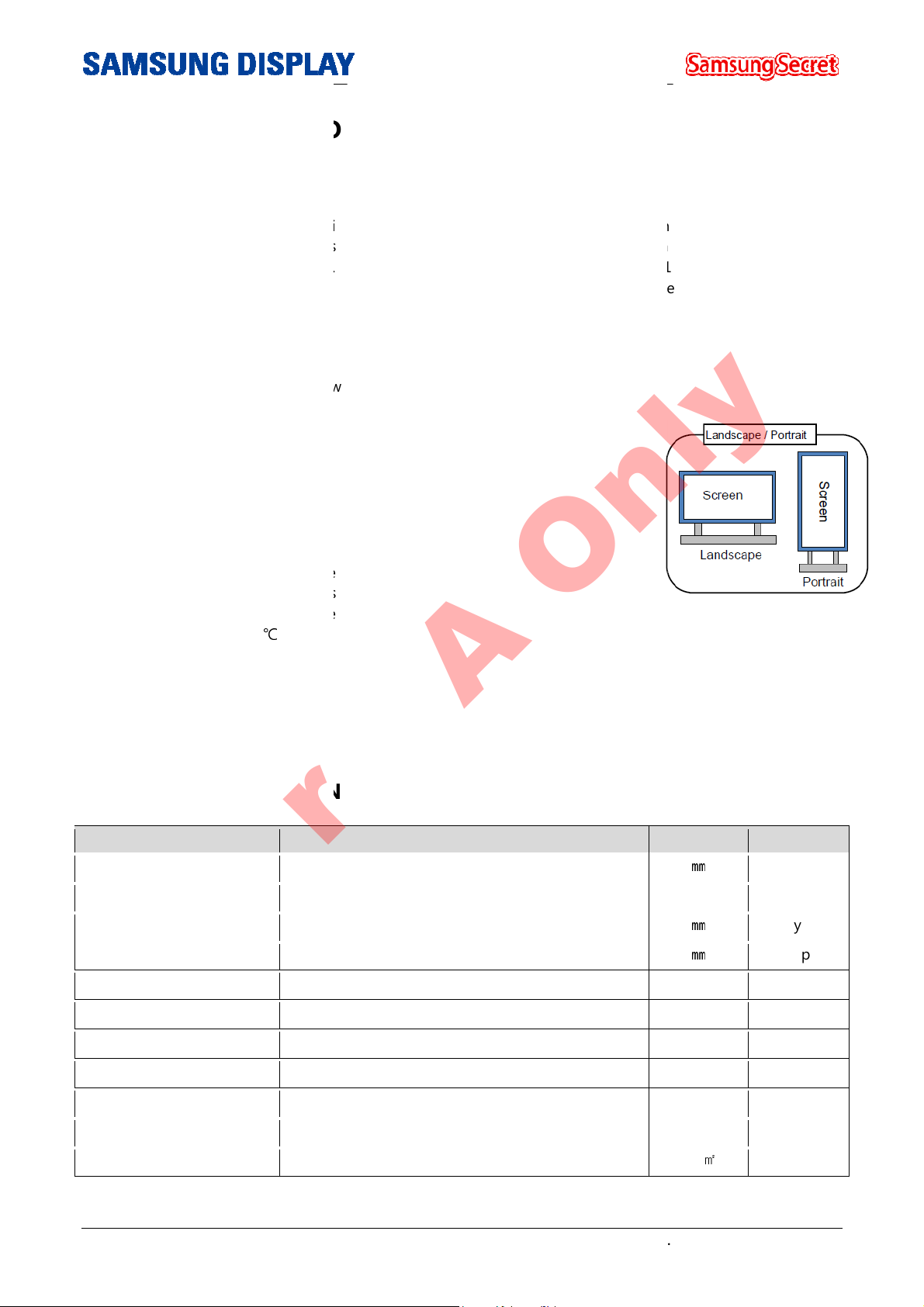
Portrait type compatible
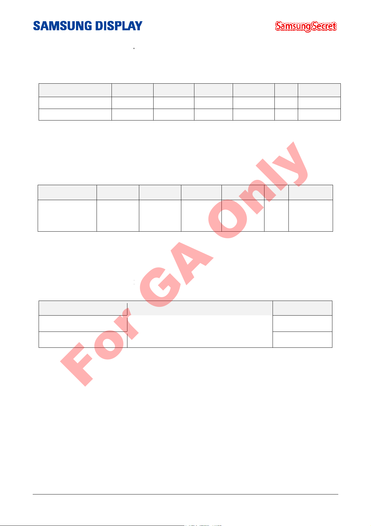
GENERAL INFORMATION
Items
Surface Treatment
Luminance of White
Rev.No. 0
FT(Thin Film Transistor) as
0” model has a resolution of 1920 x 1080 pixels (16:9) can
Specification
Haze 44% / 3H
700(Typ)
Unit Note
㎜
㎜
㎜
Anti-Glare
cd/㎡
For GA Only
DESCRIPTION
This model uses a
PBA and BLU(Back light Unit) Ass’y
display up to 16.7
FEATURES
High contrast ratio & aperture ratio
SVA(Super Vertical Align) mode
Wide viewing angle (±178°)
High speed response
FHD(1920X1080) resolution (16:9)
Edge LED(Light Emitted Diode) BLU
RoHS compliance (Pb-free)
Low power consumption
DE(Data Enable) mode
2 Channel LVDS (
Landscape /
High Tni Liquid Crystal (85 )℃
–
(LCD) that uses amorphous silicon T
ass’y KIT of source
55.
APPLICATIONS
Digital Information Display (DID)
High Definition Public Monitor
Active Display area
Switching Components
Module Size
Weight
Display colors
Number of pixels
Pixel Arrangement
Display Mode
1209.6(H) X 680.4(V)
a-Si TFT active matrix
1242.2(H) x 713.0(V)
16.7M (8bits-True)
1,920 x 1,080
RGB Vertical stripe
Normally Black
10.8(D)
15,200
Typ
Typ
g Typ
Color
Pixel 16:9
Doc.No. LTI550HN06-0
Page 4 of 31
6-000-G-121227
————————————————————————————————————————————————
MECHANICAL INFORMATION
Min.
1241
712.0
9.8
lack
Horizontal Spec
Rev.No. 0
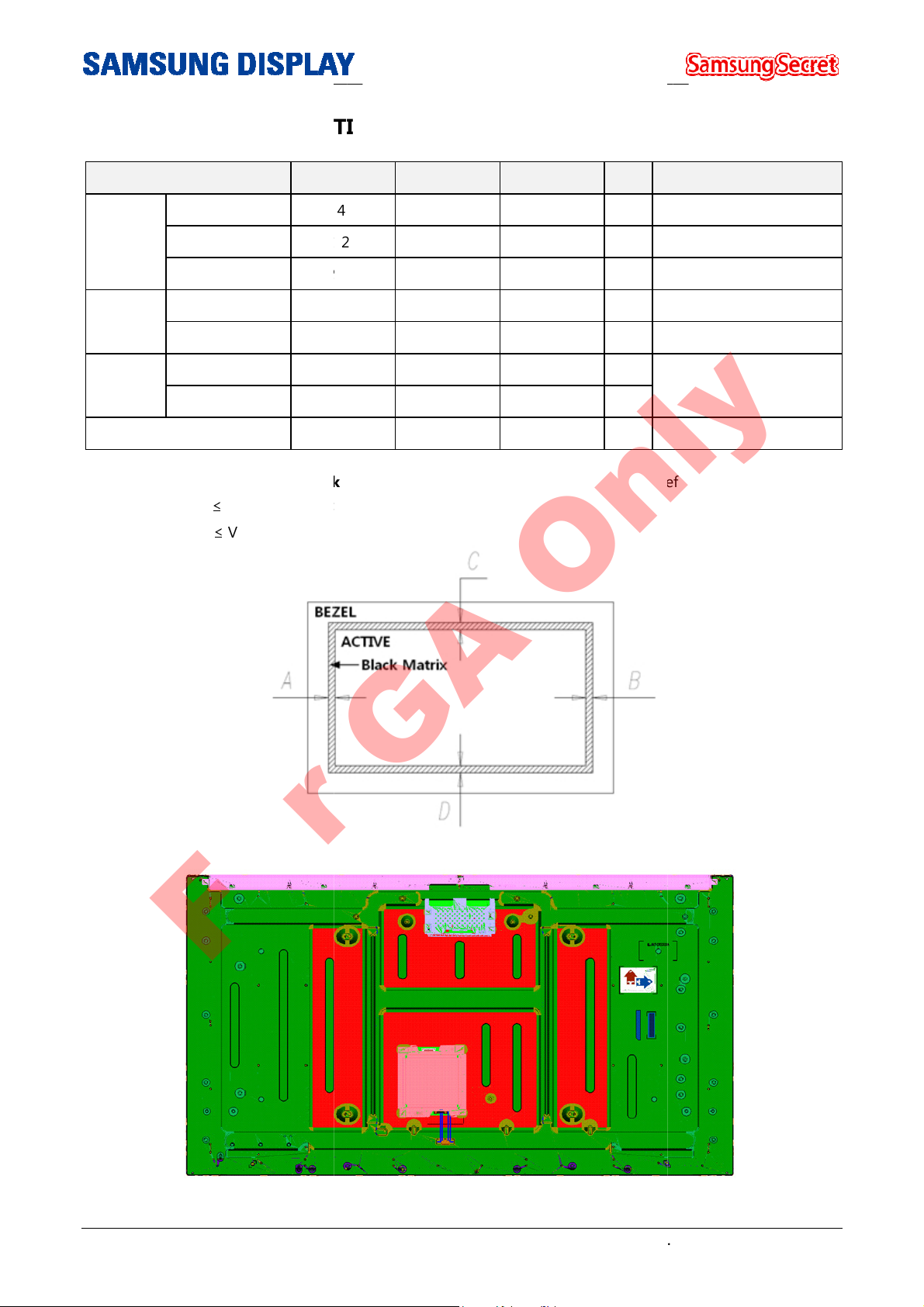
to be recorded on the spec. with referring to the drawings
For GA Only
–
Item
Horizontal (H)
Module
Size
Bezel
Open
Black
Matrix
Shift
Note (1) Measure the figure for B
Vertical (V)
Depth (D)
Horizontal (H)
Vertical (V)
Horizontal (H)
Vertical (V)
Weight
- | A - B | ≤
- | C - D | ≤ Vertical Spec
Typ. Max. Unit
.2 1242.2 1243.2 mm
713.0 714.0 mm
10.8 12.8 mm
- 1216.6 - mm
- 687.4 - mm
- - 2.0 mm
- - 2.0 mm
- 15,200 16,200 g
Matrix shift
Note
Minimum Depth (2)
(1)
.
Note (2) Measure point of Depth
Doc.No. LTI550HN06-0
Page 5 of 31
6-000-G-121227
————————————————————————————————————————————————
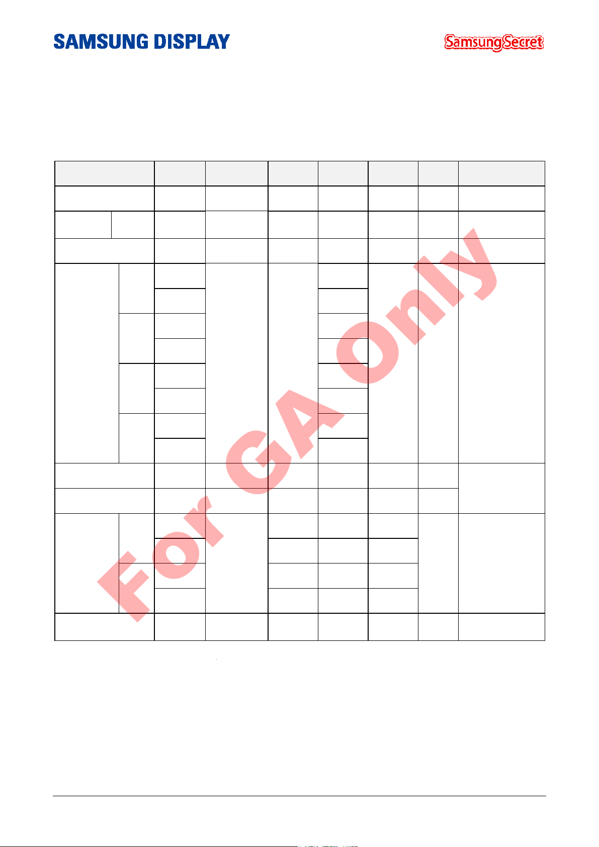
1. ABSOLUTE MAXIMUM RATINGS
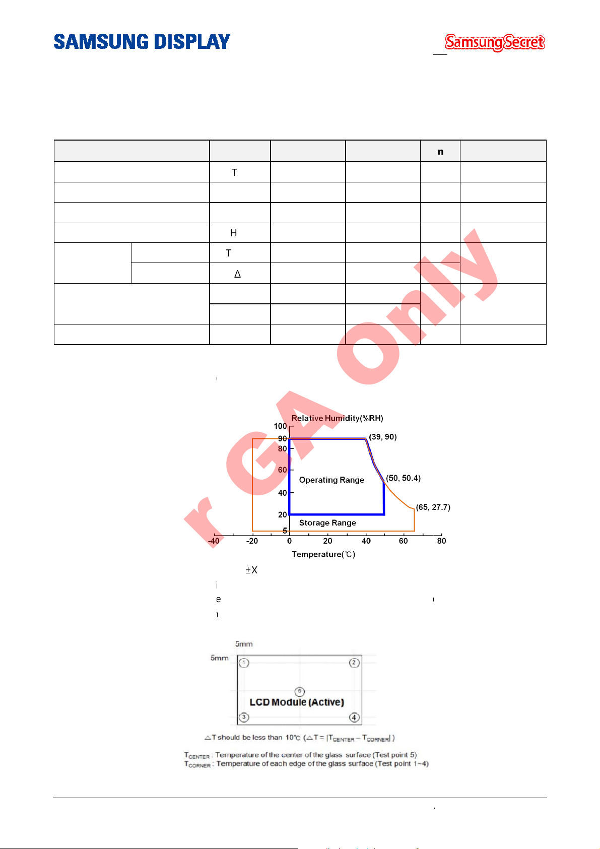
1.1 ENVIRONMENTAL ABSOLUTE RATINGS
Note (1) Temperature and relative humidity range are shown in the figure below.
(Ta ≤ 39 °C)
ave, one time for
min, 30min for X,Y,Z axis
) The fixture for the test of the vibration and shock, which holds the module to be tested shall be hard
rigid in order for the module not to be twisted or bent by the fixture.
Rev.No. 0
Unit
%RH
%RH
For GA Only
–
Item
Storage temperature
Operation Temperature
Humidity of storage
Operating humidity
Glass surface
Temperature
(Operation)
Shock ( non-operating )
Vibration (non-operating)
a. 90 % RH Max.
b. Relative Humidity is 90%
c. No condensation
Center
T Uniformity
Symbol Min. Max.
T
-20 65
STG
T
0 50
OPR
H
5 90
SUR
H
20 90
OPR
T
0 50
CENTER
∆
T - 10
Snop(X,Y)
Snop(Z) - 30
V
- 1.5
nop
or less. (Ta > 39 °C)
- 30
Note
°C (1)
°C (1)
°C
°C
G (2), (4)
G (3), (4)
±
Note (2) 11ms half sine w
Note (3) 10-300 Hz, Sweep rate 10
Note (4
and
Note (5) Definition of Test point
Doc.No. LTI550HN06-0
X, ±Y, ±Z axis.
.
Page 6 of 31
6-000-G-121227
————————————————————————————————————————————————
LECTRICAL ABSOLUTE RATINGS
Symbol
DD
Vdim
The permanent damage or defect to the device may occur if the panel is operated at the figure set,
of maximum value stated in the former spec.
limited to the conditions described above under normal
The Others Absolute Ratings
STATIC ELECTRICITY PRESSURE RSISTANCE
Rev.No. 0
The functional operation should be
operating conditions.
For GA Only
–
1.2 E
(1) TFT LCD MODULE
Item
Power Supply Voltage
Dimming Control
Note (1) Within Ta (25 ± 2 °C )
(2)
which exceeds a limit
(2) BACKLIGHT UNIT
Item
Input Supply
Voltage /
Converter
Symbol
Vcc
Min. Typ. Max.
V
10.8 - 13.2
0 - 5.25
Min.
22 24 26
Typ.
Max.
Unit
V (1),(2)
V
Unit
V
Note
Note
1.3
Item
CONTACT DISCHARGE
AIR DISCHARGE
Symbol
150pF, 330Ω, ± 10kV, 200points, 1 time/point
150pF, 330Ω, ± 20kV, 200points, 1 time/point
Min.
Operating
Operating
Doc.No. LTI550HN06-0
Page 7 of 31
6-000-G-121227
————————————————————————————————————————————————
PPLICATION INFORMATION FOR
(Digital Information Display)
s screen may display the sudden image such as an image
To extend the lifetime and optimize a function of module, the below
Normal operating condition
c. Display pattern: Moving image or image, which
Note) The sudden image on the screen can be displayed after the static image is shown in the long
The operating conditions when the module is opera
It is recommended to set the DID up in the well
b. The function of power off and screen saver
The function of periodical power
ons to prevent t
long
proper operating time: Under
b. The moving image shall be inserted between the static displays periodically.
crystal is needed.
c. The periodic changing of background color and character’s color(image)
Use the different color for background and character (image) respectively.
d. Avoid combining the color for background with the color
Note (1) Abnormal condition means all operating condition except normal operating condition.
Note (2) The moving image or black pattern is strongly recommended as a screen saver.
lifetime of DID stated in this spec is guaranteed if the DID is used under
operating conditions.
Rev.No. 0
retention.
mentioned operating
ted under the
off or a screen saver is needed when the static imag
he sudden display resulted from
for character, which has a largely different
For GA Only
–
2. A
A DID’
conditions are required.
2.1
a. Temperature: 20 ±15℃
b. Humidity: 55 ±20 %
2.2
condition.
a. Ambient condition
-
in the long-term.
2.3 Operating conditi
the static image in the
a. The
-The refresh time for liquid
-
-Change colors periodically.
luminance.
2.4 Only the
the proper
-
-term.
20 hours a day.
DID
switches regularly.
-ventilated place.
-
-term.
abnormal
e is displayed
displaying
Doc.No. LTI550HN06-0
Page 8 of 31
6-000-G-121227
————————————————————————————————————————————————
OPTICAL CHARACTERISTICS
-
Condition
* Ta = 25
Rev.No. 0
the space surrounded by the similar ambient
Unit
msec
cd/m
Degree
* Ta = 25
, VDD = 3.3V, fv=60Hz, fDCLK = 148.5MHz, IF =100% duty
150mA), VF=126.2
For GA Only
–
3.
The optical characteristics should be
setting.
Measuring equipment : TOPCON RD
Item Symbol
Contrast Ratio C/R
Response
time
Luminance of White
(At the center of screen)
Color
Chromaticity
(CIE 1931)
G-to-G
(AVG)
Red
Green
Blue
Tg
YL
RX
RY
GX
GY
BX
BY
measured in a dark room or
80S, SR-3, ELDIM EZ-Contrast Ta(25± 2 °C)
Min. Typ. Max.
- 3000 4000 -
- - 8 16
- 550 700 -
0.640
0.330
0.300
Normal
φ = 0
θ = 0
Viewing
Angle
TYP.
-0.03
0.605
0.150
0.060
TYP
+0.03
Note
- (1) SR-3
(3) RD-80S
2
-
(4) SR-3
(5), (6)
SR-3
White
Color Gamut -
Color temperature
Hor.
Viewing
Angle
Ver.
Brightness Uniformity
(9 Point)
WX
WY
-
θL
θR
θU
θD
B
uni
0.280
0.290
- 67 70 -
- - 10000 -
79 89 -
79 89 -
CR ≥ 10
79 89 -
79 89 -
- - - 25.0
± 2 °C
* If =600mA (each String
%
K
%
(5)
SR-3
(6)
SR-3
EZ-Contrast
(2)
SR-3
V (4 LED String)
Doc.No. LTI550HN06-0
Page 9 of 31
6-000-G-121227
————————————————————————————————————————————————
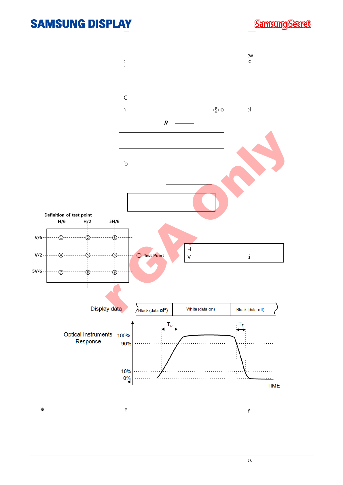
Notice (a) Setup for test equipment
The measurement should be executed in a
after lighting the backlight at the given temperature for stabilization of the backlight. This should be
measured in the center of screen.
nvironment condition : Ta = 25 ± 2 °C
contrast ratio (C/R)
Ratio of max. gray (Gmax) & min.
brightness uniformity at 9 points ( Test pattern : Full white )
G : Average response time between the whole gray scale to the whole gray scale.
Rev.No. 0
stable, windless and dark room between
of the panel
H : Horizontal Length of Active Area
V : Vertical height of Active Area
For GA Only
The e
Note (1) Definition of
–
40min and 60min
: The
Note (4) Definition of
gray (Gmin) at the center point ⑤
G
C R
/
Gmax : Luminance in all white pixels
Gmin : Luminance in all black pixels.
Buni
= ∗
100
Bmax : Maximum brightness
Bmin : Minimum brightness
max
=
G
B B
( max min)
min
B
−
max
.
Note (3) Definition of Response time
※
G-to-
Doc.No. LTI550HN06-0
: Sume of Tr, Tf
Page 10 of 31
6-000-G-121227
 Loading...