

Samsung LTA260AP01 Datasheet
Product Information
Product Information
Customer : DATE : Mar. 25, 2008
SAMSUNG TFT--
SAMSUNG TFT
SAMSUNG TFT-LCD
MODEL
MODEL
MODEL : LTA260AP01
The Information Described in this Specification is Preliminary and can be changed without prior notice
NOTE :
www.jxlcd.com
www.jxlcd.com
Customer’’
Customer
LCD
LCD
: LTA260AP01
: LTA260AP01
APPROVAED BY
s Approval
s Approval
DATE
Mar. 25, 2008
SIGNATURE
Samsung Electronics Co . , LTD.
MODEL LTA260AP01 Doc. No 06-000-G-080325 Page
DATE
LCD Business
PREPARED BY
Bong u Lee
DATE
Mar. 25, 2008
1 / 27
Contents
Revision History -------------------------------------------------------------------------------------------- (3)
General Description --------------------------------------------------------------------------------------- (4)
General Information --------------------------------------------------------------------------------------- (4)
1. Absolute Maximum Ratings -------------------------------------------------------------------------- (5)
2. Optical Characteristics --------------------------------------------------------------------------------- (6)
3. Electrical Characteristics ------------------------------------------------------------------------------- (9)
3.1 TFT LCD Module
3.2 Back Light Unit
3.3 Inverter Input & Specification
4. Block Diagram ------------------------------------------------------------------------------------------- (12)
5. Input Terminal Pin Assignment --------------------------------------------------------------------- (13)
4.1 Input Signal & Power
4.2 Inverter Input Pin Configuration
4.3 Inverter Input Power Sequence
4.4 LVDS Interface
4.5 Input Signals, Basic Display Colors and Gray Scale of Each Color
6. Interface Timing ---------------------------------------------------------------------------------------- (18)
5.1 Timing Parameters (DE only mode)
5.2 Timing Diagrams of interface Signal (DE only mode)
5.3 Power ON/OFF Sequence
7. Outline Dimension -------------------------------------------------------------------------------------- (21)
8. Packing --------------------------------------------------------------------------------------------------- (23)
9. Marking & Others ---------------------------------------------------------------------------------------(24)
10. General Precaution ------------------------------------------------------------------------------------ (25)
10.1 Handling
10.2 Storage
10.3 Operation
10.4 Operation Condition Guide
10.5 Others
www.jxlcd.com
www.jxlcd.com
MODEL LTA260AP01 Doc. No 06-000-G-080325 Page
2 / 27
* Revision History
Date Rev. No Page Summary
Mar. 25
2008
000 all First issued
www.jxlcd.com
www.jxlcd.com
MODEL LTA260AP01 Doc. No 06-000-G-080325 Page
3 / 27
General Description
Description
LTA260AP01 is a color active matrix liquid crystal display (LCD) that uses amorphous silicon
TFT(Thin Film Transistor) as switching components. This model is composed of a TFT LCD
panel, a driver circuit and a back light unit. The resolution of a 26.0“ is
1366 x 768 and this model can display up to 16.7 million colors with wide viewing angle of 89
or higher in all directions. This panel is intended to support applications to provide a excellent
performance for Flat Panel Display such as Home-alone Multimedia TFT-LCD TV and High
Definition TV
Features
RoHS (Directive 2002/95/EC) compliance ( Pb-free )
High contrast ratio & aperture ratio with wide color gamut
APVA(Super Patterned Vertical Align) mode
Wide viewing angle (± 178°)
High speed response & Natural Motion
FHD resolution (16:9)
Low Power consumption
Direct U Type 5 CCFLs(Cold Cathode Fluorescent Lamp)
DE(Data Enable) mode
LVDS (Low Voltage Differential Signaling) interface (1pixel/clock)
°
General Information
www.jxlcd.com
www.jxlcd.com
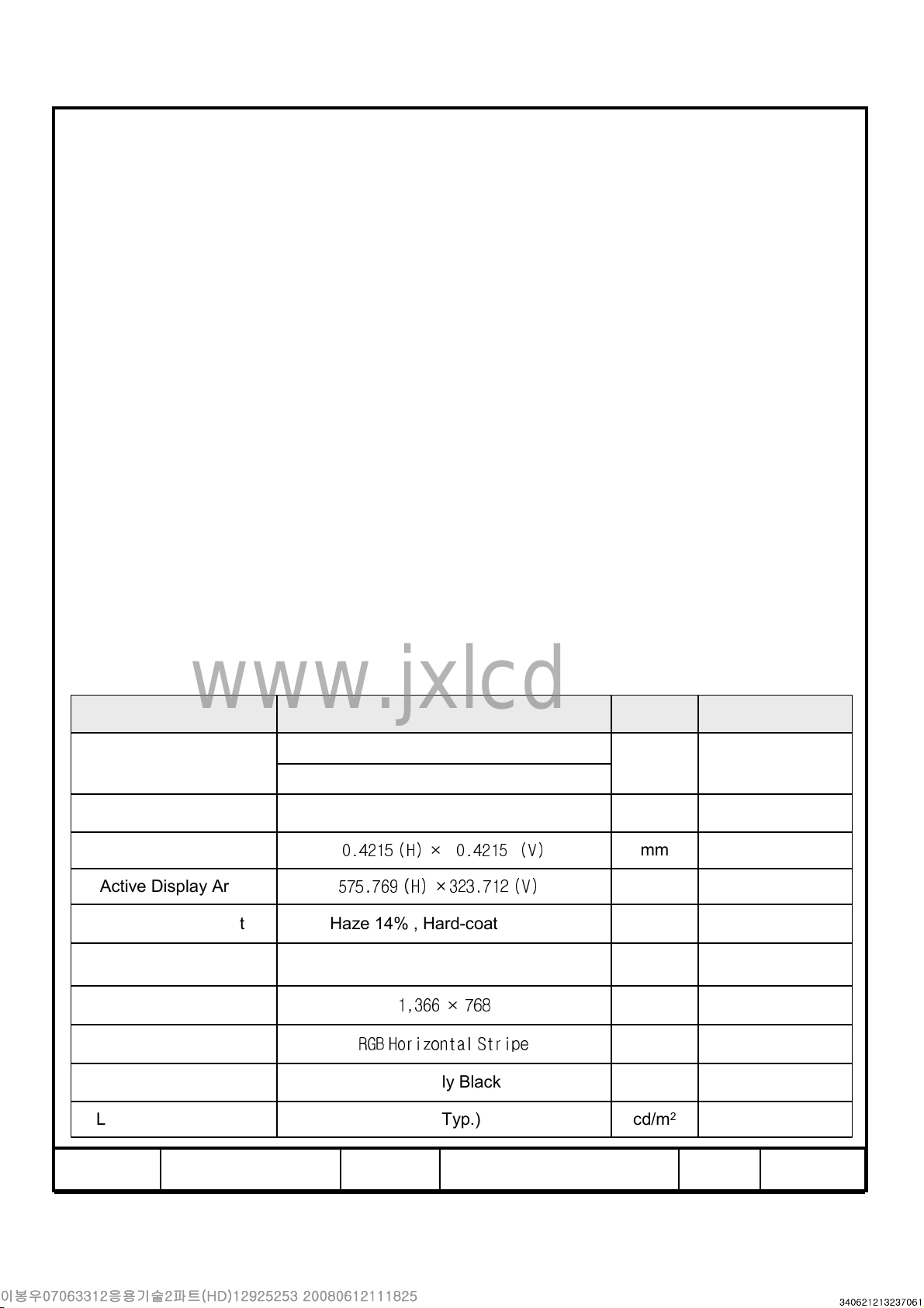
Items Specification Unit Note
Module Size
Weight 5500(Max.) g
Pixel Pitch
Active Display Area
Surface Treatment Haze 14% , Hard-coating (3H)
Display Colors 8bit – 16.7 M colors
Number of Pixels
Pixel Arrangement
Display Mode Normally Black
Luminance of White 450(Typ.) cd/m
626.0(H
0.4215 (H) × 0.4215 (V)
575.769 (H) ×323.712 (V)
RGB Horizontal Stripe
) x 373.0(V
Typ
50.5(D
1,366 × 768
MAX
)
Typ
)
) mm
mm ± 1.0mm
mm
pixel
2
MODEL LTA260AP01 Doc. No 06-000-G-080325 Page
4 / 27
1. Absolute Maximum Ratings
If the condition exceeds maximum ratings, it can cause malfunction or unrecoverable
damage to the device.
Item Symbol Min. Max. Unit Note
Power Supply Voltage V
Storage temperature T
Glass surface
Temperature
(operation)
Shock ( non - operating ) S
Vibration ( non - operating ) V
Note (1) Ta= 25 ± 2 °C
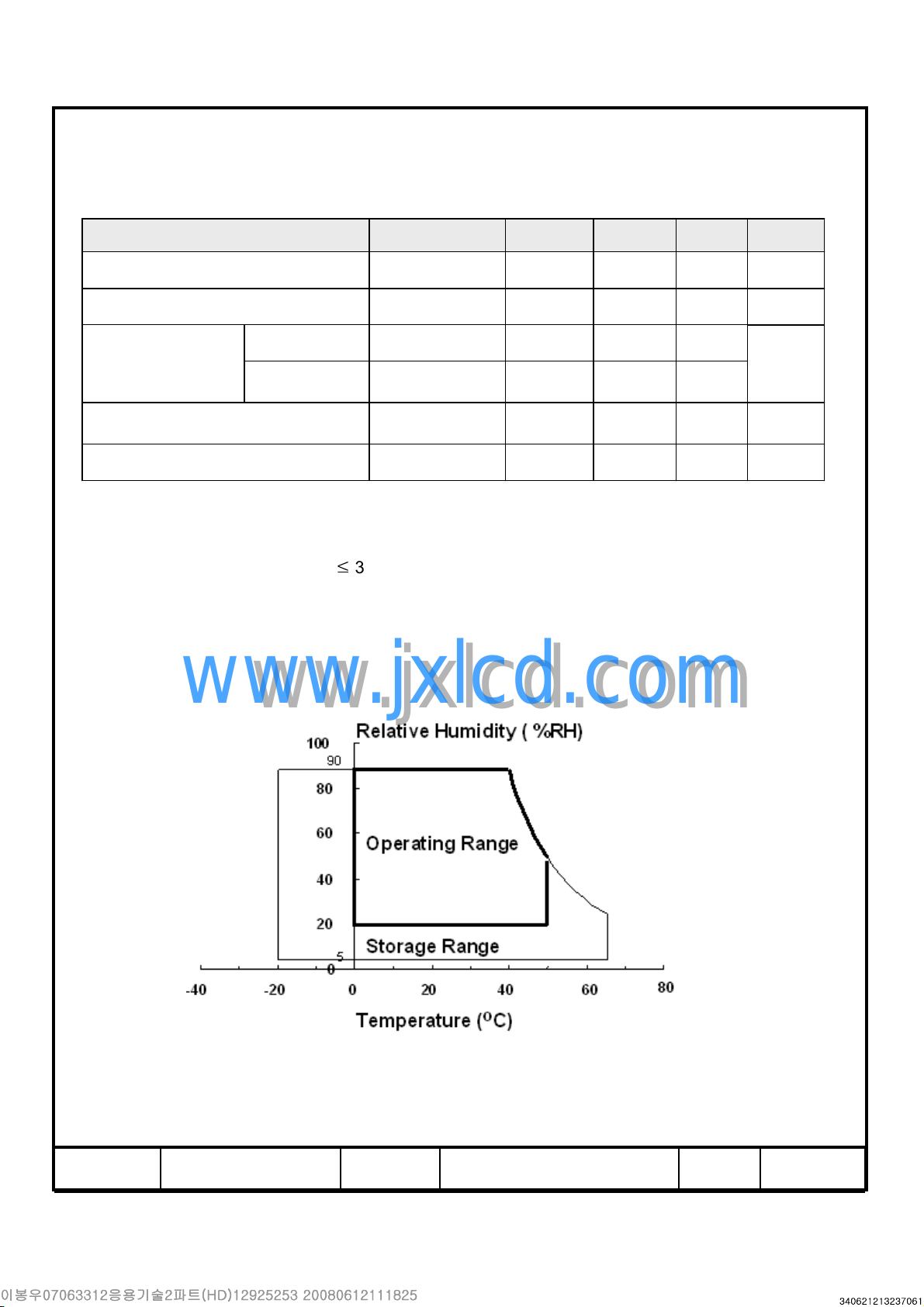
(2) Temperature and relative humidity range are shown in the figure below.
a. 90 % RH Max. (Ta ≤39 °C)
b. Relative Humidity is 90% or less. (Ta > 39 °C)
c. No condensation
(3) 11ms, sine wave, one time for ± X, ± Y, ± Z axis
(4) 10-300 Hz, Sweep rate 10min, 30min for X,Y,Z axis
www.jxlcd.com
www.jxlcd.com
Center T
T. uniformity △T 0 10
DD
STG
OPR
NOP
nop
10.8 13.2 V (1)
-20 65
0 50
- 50 G (3)
- 1.5 G (4)
℃
℃
℃
(2)
(2)
Fig. Temperature and Relative humidity range
MODEL LTA260AP01 Doc. No 06-000-G-080325 Page
5 / 27
2. Optical Characteristics
The optical characteristics should be measured in a dark room or equivalent.
Measuring equipment :
(Ta = 25 ± 2°C, VDD=12V, fv= 60Hz, Dimming Max. =3.3V , f
Item Symbol Condition Min. Typ. Max. Unit Note
TOPCON BM-7,SPECTRORADIOMETER SR-3, ELDIM EZ-Contrast
DCLK
=78MHz)
Contrast Ratio
(Center of screen)
Response
Time
Luminance of White
(Center of screen)
Color
Chromaticity
(CIE 1931)
Color Gamut - - 72 - %
Color Temperature - - 10000 - K
G-to-G Tg - 8 16 msec
Red
Green
Blue
White
www.jxlcd.com
www.jxlcd.com
C/R
Y
L
Normal
Rx
Ry 0.337
Gx 0.283
Gy 0.597
Bx 0.146
By 0.071
Wx 0.280
Wy 0.290
θL,R=0
θU,D=0
Viewing
Angle
2500 3,000 -
400 450 - cd/m
0.646
TYP.
-0.03
TYP.
+0.03
(1)
SR-3
(3)
MB-7
2
(4)
SR-3
(5),(6)
SR-3
(5)
SR-3
(5)
SR-3
Hor.
Viewing
Angle
Ver.
Brightness Uniformity of
White (9 Points)
θ
L
θ
R
θ
U
θ
D
B
uni
C/R≥10
75 89 -
75 89 -
Degree
75 89 -
75 89 -
- - 25 %
- Test Equipment Setup
The measurement should be executed in a stable, windless and dark room between
40min and 60min after lighting the back light at the given temperature for stabilization
of the back light. This should be measured in the center of screen.
Dimming Max. =3.3V
Environment condition : Ta = 25 ± 2 °C
MODEL LTA260AP01 Doc. No 06-000-G-080325 Page
(6)
EZ-Contrast
(2)
SR-3
6 / 27
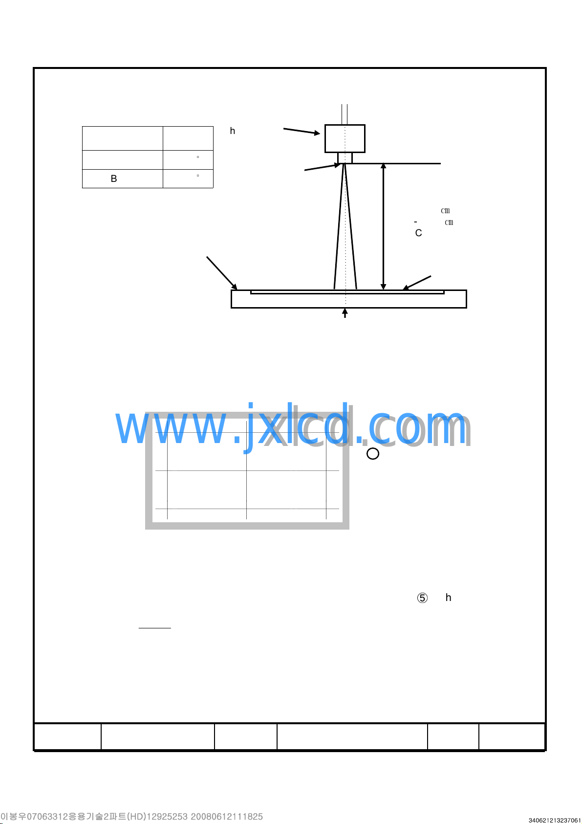
Photo detector Field
G
min
Photo detector
SR-3 1
BM-7 2
TFT - LCD Module
- Definition of test point
320 960 1600
180
www.jxlcd.com
www.jxlcd.com
540
⑨⑨⑨⑨
⑥⑥⑥⑥
°
°
Field
The center of the screen
⑧⑧⑧⑧
⑦⑦⑦⑦
⑤⑤⑤⑤ ④④④④
SR-3 : 50
BM-7 : 50
EZ-Contrast : 0cm
LCD Panel
Active Area
Test Point
㎝
㎝
900
Note (1) Definition of Contrast Ratio (C/R)
: Ratio of gray max (Gmax) & gray min (Gmin) at the center point ⑤of the panel
G
C R
/
MODEL LTA260AP01 Doc. No 06-000-G-080325 Page
max
=
Gmax : Luminance with all pixels white
Gmin : Luminance with all pixels black
①①①①②②②②③③③③
7 / 27
Note (2) Definition of 9 points brightness uniformity of White At Max dimming voltage
B
−
max
B B
Buni
= ∗
Bmax : Maximum brightness
Bmin : Minimum brightness
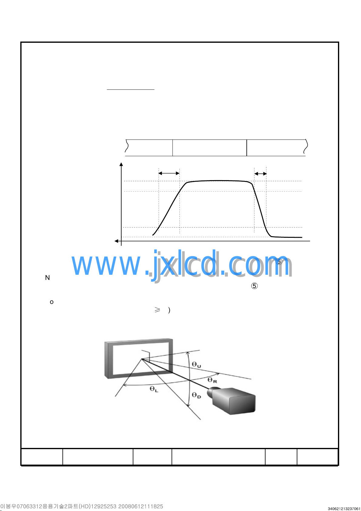
Note (3) Definition of Response time : Sum of Tr, Tf
( max min)
100
Display data
Optical Instruments
Response
Note (4) Definition of Luminance of White : Luminance of white at center point
www.jxlcd.com
Note (5) Definition of Color Chromaticity (CIE 1931)
Note (6) Definition of Viewing Angle
www.jxlcd.com
Color coordinate of Red, Green, Blue & White at center point
: Viewing angle range (C/R ≥10)
100%
90%
10%
0%
Black (data
off)
T
R
White (data on)
Black (data off)
T
F
⑤
TIME
⑤
MODEL LTA260AP01 Doc. No 06-000-G-080325 Page
8 / 27
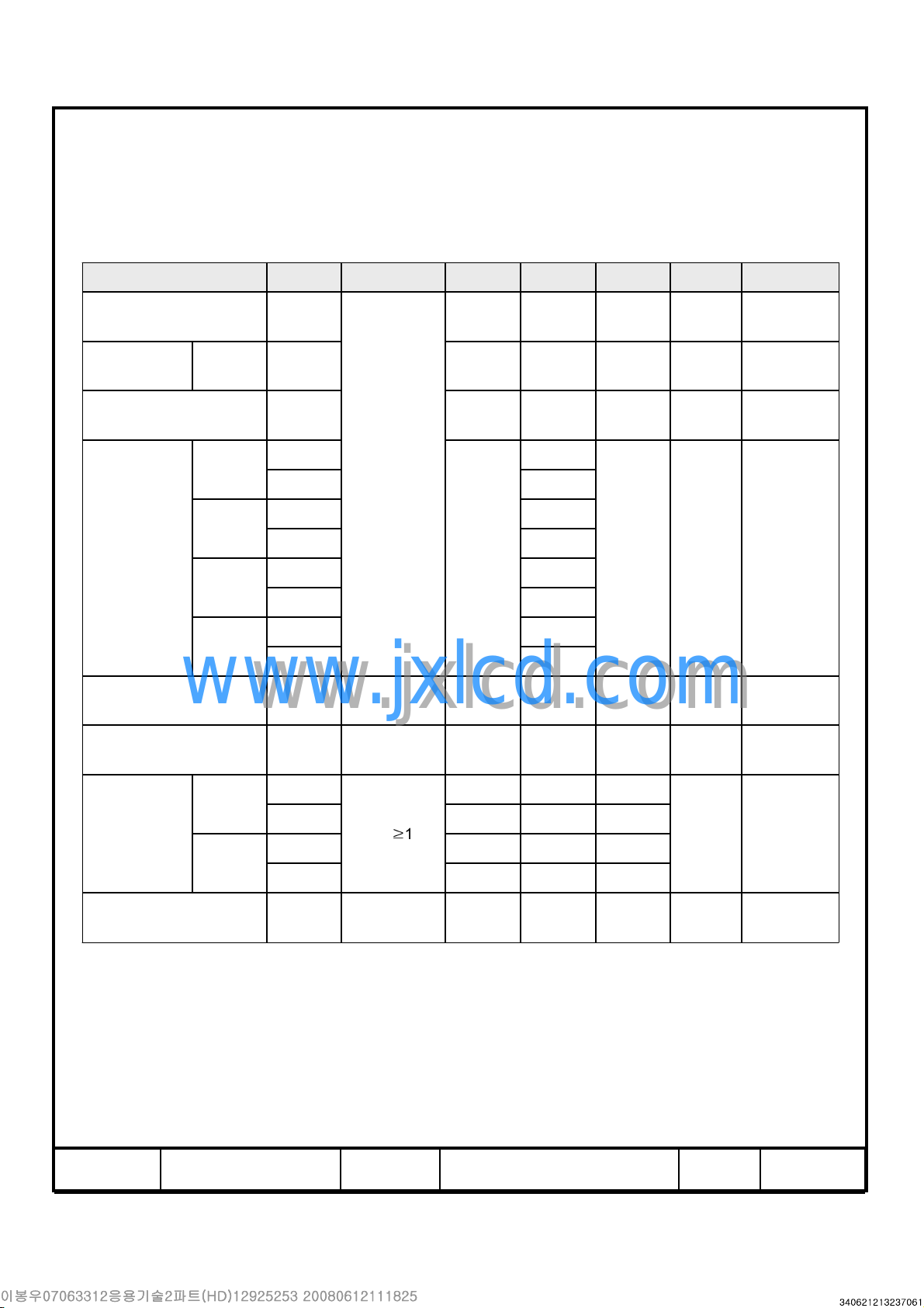
3. Electrical Characteristics
3.1 TFT LCD Module
The connector for display data & timing signal should be connected.
Ta = 25°C ± 2 °C
Item Symbol Min. Typ. Max. Unit Note
Voltage of Power Supply V
Current
of Power
Supply
Vsync Frequency f
Hsync Frequency f
Main Frequency f
Rush Current I
Note (1) The ripple voltage should be controlled under 10% of VDD.
(2) fV=60Hz, f
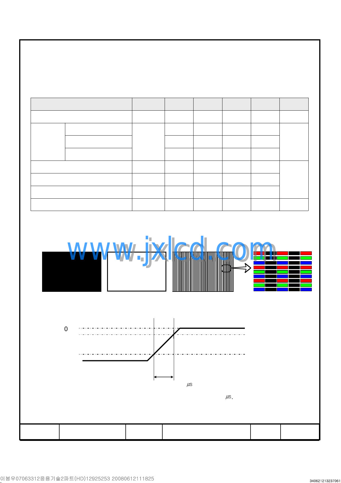
(3) Power dissipation check pattern (LCD Module only)
a) Black Pattern b) White Pattern c) V-Stripe
(a) Black
(c) V-Stripe 0.65 0.75 0.85 A
DCLK
= 78MHz, VDD= 12.0V, DC Current.
www.jxlcd.com
www.jxlcd.com
DD
I
DD
V
H
DCLK
RUSH
10.8 12 13.2 V (1)
0.35 0.45 0.55 A
50 60 66 Hz
44 48 53 kHz
72 78 85 MHz
- - 4 A (4)
(2),(3)(b) White 0.45 0.55 0.65 A
(4) Measurement Conditions
V
100%
90%
10%
GND
T
=470
RUSH
Rush Current I
MODEL LTA260AP01 Doc. No 06-000-G-080325 Page
can be measured when T
RUSH
㎲
. is 470㎲.
RUSH
DD
9 / 27
 Loading...