

Page 1

SERVICE
Manual
TFT-LCD TV
Fashion Feature
LCD-TV
Chassis
GMO32MU
GMO40KU
GMO46KU
GMO46KU
Model
LN-S3292D
LN-S4092D
LN-S4692D
LN46M52BD
- RF, 2HDMI, PC(Analog), Component, Video,
S-Video, Digital TV
- Brightness : 500cd/
- Contrast ratio : 3000 : 1
- Respense time : 32" - 8ms, 40"/46" - 16ms
- Dynamic contrast
- PIP
Page 2

ii
Copyright
©2006 by Samsung Electronics Co., Ltd.
All rights reserved.
This manual may not, in whole or in part, be copied,
photocopied, reproduced, translated, or converted to
any electronic or machine readable form without prior
written permission of Samsung Electronics Co., Ltd.
GMO32MU / GMO40KU / GMO46KU Service
Manual
First edition April 2006.
Printed in Korea.
Trademarks
Samsung is the registered trademark of Samsung
Electronics Co., Ltd.
GMO32MU / GMO40KU / GMO46KU and
MacMaster Cable Adapter are trademarks of Samsung
Electronics Co., Ltd.
Macintosh, Power Macintosh are trademarks of Apple
Computer, Inc.
All other trademarks are the property of their respective
owners.
Page 3

1 Precautions 1-1
1-1 Safety Precautions
1-1
1-2 Servicing Precautions
1-2
1-3 Electrostatically Sensitive Devices (ESD) Precautions
1-2
1-4 Installation Precautions
1-3
2 Product specifications
2-1
2-1 Fashion Feature
2-1
2-2 Specifications
2-2
2-3 Option Specification
2-6
3 Alignments and Adjustments
3-1
3-1 General Alignment Instuction
3-1
3-2 Factory Mode Adjustments
3-2
3-3 White Balance - Calibration
3-9
3-4 White Ratio (Balance) Adjustment
3-10
3-5 Servicing Information
3-11
4 Troubleshooting
4-1
4-1 No Power
4-1
4-2 No Video (Analog PC Signal)
4-2
4-3 No Video (HDMI - Digital Signal))
4-4
4-4 No Picture (Tuner_CVBS)
4-6
4-5 No Picture (Tuner DTV TS)
4-8
4-6 No Picture (Video CVBS)
4-10
4-7 No Picture(S-Video Y/C)
4-11
4-8 No Picture(Component1, 2 : 480i, 480p, 720p, 1080i [ Y, Pb, Pr] )
4-13
4-9 No Sound
4-15
5 Exploded View and Parts List
5-1
5-1 LN-S3292D Exploded View
5-1
5-2 LN-S3292D Parts list
5-2
5-3 LN-S4092D Exploded View
5-3
5-4 LN-S4092D Parts list
5-4
5-5 LN-S4692D Parts list
5-5
5-6 LN-S4692D / LN46M52BD Parts list
5-6
6 Electrical Parts List
6-1
6-1 LNS3292D Parts List
6-1
6-2 LNS4092D Parts List
6-27
6-3 LNS4692D / LN46M52BD Parts List
6-55
Contents
Page 4

7 Block Diagram 7-1
8 Wiring Diagram
8-1
8-1 Wiring Diagram
8-1
9 Schematic Diagrams
9-1
10 Operating Instructions and Installation
10-1
10-1 Front
10-1
10-2 Connection Panel
10-2
10-3 Remote Control
10-4
11 Disassembly and Reassembly
11-1
11-1 Disassembly
11-1
11-2 Reassembly
11-3
12 Schematic Diagram
12-1
12-1 Main PCB Layout
12-1
12-2 LN-S3292D Power
12-2
12-2 LN-S4092D Power
12-3
12-2 LN-S4692D / LN46M52BD Power
12-4
13 Circuit Descriptions
13-1
13-1 Block description
13-1
14 Reference Infomation
14-1
14-1 Technical Terms
14-1
14-2 Pin Assignments
14-4
14-3 Timing Chart
14-6
14-4 Panel Description
14-10
Contents
Page 5
Samsung Electronics Co.,Ltd.
416, Maetan-3Dong, Yeongtong-Gu, Suwon City,
Gyeonggi-Do, Korea, 443-742
Printed in Korea
P/N : BN82-00146A-01
URL : http://itself.sec.samsung.co.kr/
-This Service Manual is a property of Samsung
Electronics Co., Ltd.
Any unauthorized use of Manual can be punished
under applicable International and/or domestic law.
Page 6
1 Precautions
1-1
1-1-1 Warnings
1. For continued safety, do not attempt to modify the circuit
board.
2. Disconnect the AC power and DC power jack before
servicing.
1-1-2
Ser vicing the LCD Monitor
1. When servicing the LCD Monitor, Disconnect the AC
line cord from the AC outlet.
2. It is essential that service technicians have an accurate
voltage meter available at all times. Check the
calibration of this meter periodically.
1-1-3 Fire and Shock Hazard
Before returning the monitor to the user, perform the
following safety checks:
1. Inspect each lead dress to make certain that the leads are
not pinched or that hardware is not lodged between the
chassis and other metal parts in the monitor.
2. Inspect all protective devices such as nonmetallic control
knobs, insulating materials, cabinet backs, adjustment
and compartment covers or shields, isolation resistorcapacitor networks, mechanical insulators, etc.
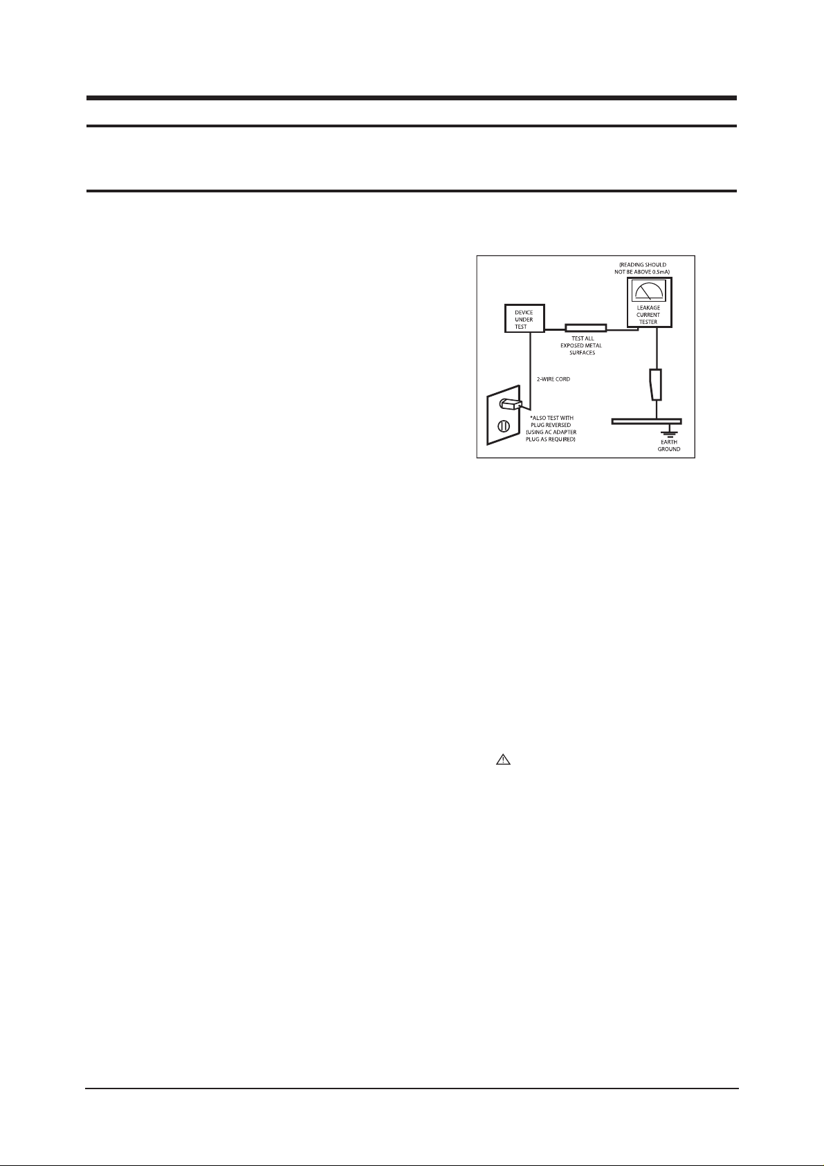
3. Leakage Current Hot Check (Figure 1-1):
WARNING : Do not use an isolation
transformer during this test.
Use a leakage current tester or a metering system that
complies with American National Standards Institute
(ANSI C101.1, Leakage Current for Appliances), and
Underwriters Laboratories (UL Publication UL1410,
59.7).
Figure 1-1. Leakage Current Test Circuit
4. With the unit completely reassembled, plug the AC line
cord directly into a 120V AC outlet. With the unit’s AC
switch first in the ON position and then OFF, measure
the current between a known earth ground (metal water
pipe, conduit, etc.) and all exposed metal parts,
including: metal cabinets, screwheads and control shafts.
The current measured should not exceed 0.5 milliamp.
Reverse the power-plug prongs in the AC outlet and
repeat the test.
1-1-4 Product Safety Notices
Some electrical and mechanical parts have special safetyrelated characteristics which are often not evident from visual
inspection. The protection they give may not be obtained by
replacing them with components rated for higher voltage,
wattage, etc. Parts that have special safety characteristics are
identified by on schematics and parts lists. A substitute
replacement that does not have the same safety characteristics
as the recommended replacement part might create shock, fire
and/or other hazards. Product safety is under review
continuously and new instructions are issued whenever
appropriate.
1 Precautions
Follow these safety, servicing and ESD precautions to prevent damage and to protect against potential hazards such as electrical shock.
1-1 Safety Precautions
Page 7

1 Precautions
1-2
1-2-1 General Ser vicing
Precautions
1. Always unplug the unit’s AC power cord from the AC
power source and disconnect the DC Power Jack before
attempting to:
(a) remove or reinstall any component or assembly, (b)
disconnect PCB plugs or connectors, (c) connect a test
component in parallel with an electrolytic capacitor.
2. Some components are raised above the printed circuit
board for safety. An insulation tube or tape is sometimes
used. The internal wiring is sometimes clamped to
prevent contact with thermally hot components. Reinstall
all such elements to their original position.
3. After servicing, always check that the screws,
components and wiring have been correctly reinstalled.
Make sure that the area around the serviced part has not
been damaged.
1. Immediately before handling any semiconductor
components or assemblies, drain the electrostatic charge
from your body by touching a known earth ground.
Alternatively, wear a discharging wrist-strap device. To
avoid a shock hazard, be sure to remove the wrist strap
before applying power to the monitor.
2. After removing an ESD-equipped assembly, place it on a
conductive surface such as aluminum foil to prevent
accumulation of an electrostatic charge.
3. Do not use freon-propelled chemicals. These can
generate electrical charges sufficient to damage ESDs.
4. Use only a grounded-tip soldering iron to solder or
desolder ESDs.
5. Use only an anti-static solder removal device. Some
solder removal devices not classified as “anti-static” can
generate electrical charges sufficient to damage ESDs.
4. Check the insulation between the blades of the AC plug
and accessible conductive parts (examples: metal panels,
input terminals and earphone jacks).
5. Insulation Checking Procedure: Disconnect the power
cord from the AC source and turn the power switch ON.
Connect an insulation resistance meter (500 V) to the
blades of the AC plug.
The insulation resistance between each blade of the AC
plug and accessible conductive parts (see above) should
be greater than 1 megohm.
6. Always connect a test instrument’s ground lead to the
instrument chassis ground before connecting the positive
lead; always remove the instrument’s ground lead last.
6. Do not remove a replacement ESD from its protective
package until you are ready to install it. Most
replacement ESDs are packaged with leads that are
electrically shorted together by conductive foam,
aluminum foil or other conductive materials.
7. Immediately before removing the protective material
from the leads of a replacement ESD, touch the
protective material to the chassis or circuit assembly into
which the device will be installed.
Caution:Be sure no power is applied to the
chassis or circuit and observe all
other safety precautions.
8. Minimize body motions when handling unpackaged
replacement ESDs. Motions such as brushing clothes
together, or lifting your foot from a carpeted floor can
generate enough static electricity to damage an ESD.
1-3
Electrostatically Sensitive Devices (ESD) Precautions
Some semiconductor (solid state) devices can be easily damaged by static electricity. Such components are commonly called
Electrostatically Sensitive Devices (ESD). Examples of typical ESD are integrated circuits and some field-effect transistors. The
following techniques will reduce the incidence of component damage caused by static electricity.
1-2 Ser vicing Precautions
WARNING: An electrolytic capacitor installed with the wrong polarity might explode.
Caution: Before servicing units covered by this service manual, read and follow the Safety Precautions section
of this manual.
Note: If unforeseen circumstances create conflict between the following servicing precautions and any of the safety
precautions, always follow the safety precautions.
Page 8

1 Precautions
1-3
1-4 Installation Precautions
1. For safety reasons, more than two people are
required for carrying the product.
2. Keep the power cord away from any heat emitting
devices, as a melted covering may cause fire or
electric shock.
3. Do not place the product in areas with poor
ventilation such as a bookshelf or closet. The
increased internal temperature may cause fire.
4. Bend the external antenna cable when connecting
it to the product. This is a measure to protect it
from being exposed to moisture. Otherwise, it
may cause a fire or electric shock.
5. Make sure to turn the power off and unplug the
power cord from the outlet before repositioning
the product. Also check the antenna cable or the
external connectors if they are fully unplugged.
Damage to the cord may cause fire or electric
shock.
6. Keep the antenna far away from any high-voltage
cables and install it firmly. Contact with the highvoltage
cable or the antenna falling over may
cause fire or electric shock.
7. When installing the product, leave enough space
(10cm) between the product and the wall for
ventilation purposes.
A rise in temperature within the product may cause fire.
Page 9

1 Precautions
1-4
Memo
Page 10

2 Product Specifications
2-1
2 Product Specifications
2-1 Fashion Feature
- RF, 2HDMI, PC(Analog), Component, Video, S-Video, Digital TV
- Brightness : 500cd/
- Contrast ratio : 3000 : 1
- Respense time : 32" - 8ms, 40"/46" - 16ms
- Dynamic contrast
- PIP
Page 11
2 Product Specifications
2-2
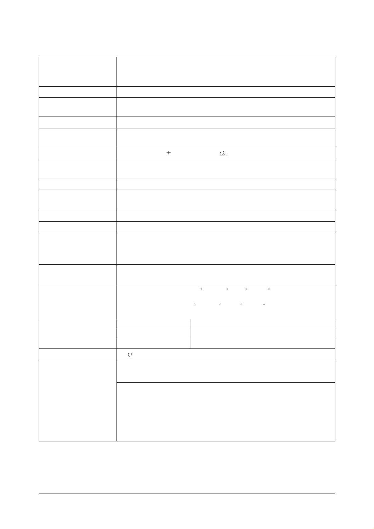
2-2 Specifications
2-2-1 LN-S3292D Specifications
LCD Panel
TFT-LCD panel, RGB vertical stripe, normaly white, 32-Inch viewable, 0.1460 (H) x 0.4365(V)mm pixel pitch
Scanning Frequency Horizontal : 30 kHz ~ 61 kHz (Automatic)
Vertical : 60 Hz ~ 75 Hz (Automatic)
Display Colors 16.7 Million colors
Maximum Resolution Horizontal : 1360 Pixels
Vertical : 768 Pixels
Input Video Signal Analog 0.7 Vp-p
5% positive at 75 , internally terminated
Input Sync Signal Type : Seperate H/V
Level : TTL level
Maximum Pixel Clock rate
80 MHz
Active Display
Horizontal/Vertical
AC power voltage & Frequency
AC 110, 60Hz
Power Consumption < 150 W ( < 1W, stand by )
Dimensions(W x D x H)
Set 804 X 131.1 X 563.1 mm_without stand
804 X 249 X 622.5 mm_ with stand
Weight
Set(With stand) 19.2 Kg
Environmental Considerations
Operating Temperature : 50 F ~ 104 F (10 C ~ 40 C)
Operating Humidity : 10 % ~ 80 %
Storage Temperature : -4 F ~ 113 F (-20 C ~ 45 C)
Storage Humidity : 5 % ~ 95 %
TV System
Antena Input
75
- MAX Internal speaker Out : Right => 10W, Left => 10W
Sound Characteristic
- BASS Control Range : -8 dB ~ + 8dB
- TREBLE Control Range : -8 dB ~ +8 dB
- Headphone Out : 10 mW MAX
- Output Frequency : RF : 80 Hz ~ 15 kHz
A/V : 80 Hz ~ 20 kHz
System ATSC, NTSC
Item
Description
596.256 mm / 335.232 mm
Tunning Frequency Synthesize
Sound MONO, STEREO, SAP
Page 12
2 Product Specifications
2-3
2-2-2 LN-S4092D Specifications
LCD Panel
TFT-LCD panel, RGB vertical stripe, normaly white, 40-Inch viewable, 0.648 (H) x 0.648(V)mm pixel pitch
Scanning Frequency Horizontal : 30 kHz ~ 61 kHz (Automatic)
Vertical : 60 Hz ~ 75 Hz (Automatic)
Display Colors 16.7 Million colors
Maximum Resolution Horizontal : 1360 Pixels
Vertical : 768 Pixels
Input Video Signal Analog 0.7 Vp-p
5% positive at 75 , internally terminated
Input Sync Signal Type : Seperate H/V
Level : TTL level
Maximum Pixel Clock rate
80 MHz
Active Display
Horizontal/Vertical
AC power voltage & Frequency
AC 110~120 ,60Hz
Power Consumption < 240 W ( < 1W, stand by )
Dimensions(W x D x H)
Set 1004 X 115 X 680 mm_without stand
1004 X 330 X 749 mm_ with stand
Weight
Set(With stand) 27.5 Kg
Environmental Considerations
Operating Temperature : 50 F ~ 104 F (10 C ~ 40 C)
Operating Humidity : 10 % ~ 80 %
Storage Temperature : -4 F ~ 113 F (-20 C ~ 45 C)
Storage Humidity : 5 % ~ 95 %
TV System
Antena Input
75
- MAX Internal speaker Out : Right => 10W, Left => 10W
Sound Characteristic
- BASS Control Range : -8 dB ~ + 8dB
- TREBLE Control Range : -8 dB ~ +8 dB
- Headphone Out : 10 mW MAX
- Output Frequency : RF : 80 Hz ~ 15 kHz
A/V : 80 Hz ~ 20 kHz
System ATSC, NTSC
Item
Description
885.168 mm / 497.664 mm
Tunning Frequency Synthesize
Sound MONO, STEREO, SAP
Page 13
2 Product Specifications
2-4
2-2-3 LN-S4692D / LN46M52BD Specifications
LCD Panel
TFT-LCD panel, RGB vertical stripe, normaly white, 46-Inch viewable, 0.7455 (H) x 0.2495(V)mm pixel pitch
Scanning Frequency Horizontal : 30 kHz ~ 61 kHz (Automatic)
Vertical : 60 Hz ~ 75 Hz (Automatic)
Display Colors 16.7 Million colors
Maximum Resolution Horizontal : 1360 Pixels
Vertical : 768 Pixels
Input Video Signal Analog 0.7 Vp-p
5% positive at 75 internally terminated
Input Sync Signal Type : Seperate H/V
Level : TTL level
Maximum Pixel Clock rate
80 MHz
Active Display
Horizontal/Vertical 1018.353 mm / 572.544 mm
AC power voltage & Frequency
AC 110V~120V, 60Hz
Power Consumption < 330W (< 1W, stand by )
Dimensions(W x D x H)
Set 1126 X 140 X 752 mm_without stand
800 X252 X 603 mm) With stand
Weight
Set(With stand) 37.0 kg
Environmental Considerations Operating Temperature : 50 F ~ 104 F (10 C ~ 40 C)
Operating Humidity : 10 % ~ 80 %
Storage Temperature : -4
F ~ 113
F (-20 C ~ 45 C)
Storage Humidity : 5 % ~ 95 %
TV System
Antena Input
75
- MAX Internal speaker Out : Right => 10W, Left => 10W
Sound Characteristic
- BASS Control Range : -8 dB ~ + 8dB
- TREBLE Control Range : -8 dB ~ +8 dB
- Headphone Out : 10 mW MAX
- Output Frequency : RF : 80 Hz ~ 15 kHz
A/V : 80 Hz ~ 20 kHz
System ATSC, NTSC
Item
Description
Tunning Frequency Synthesize
Sound MONO, STEREO, SAP
Page 14
2 Product Specifications
2-5
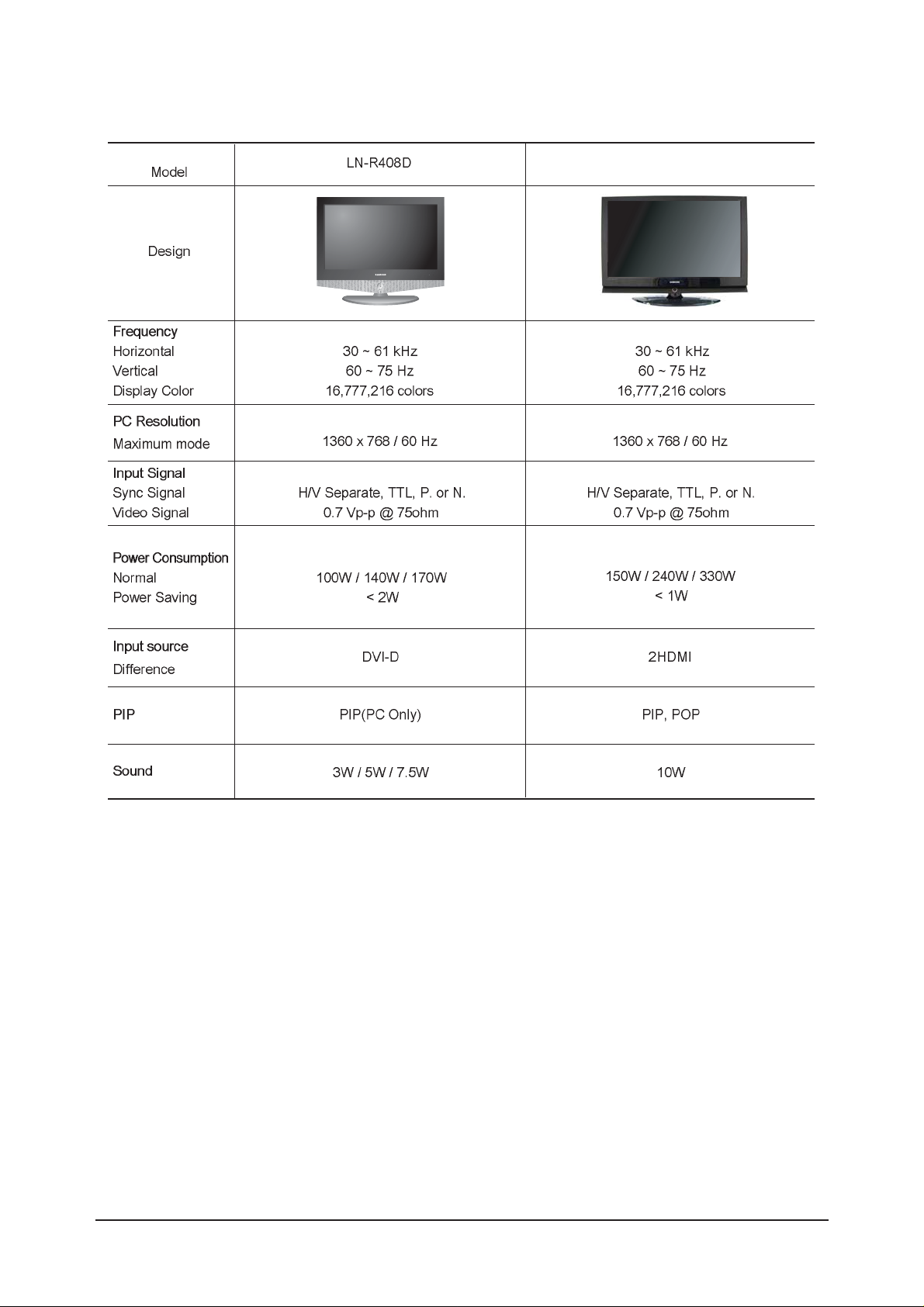
2-2-4 Spec Comparison
LN-S3292D / LN-S4092D / LN-S4692D
Page 15
2 Product Specifications
2-6
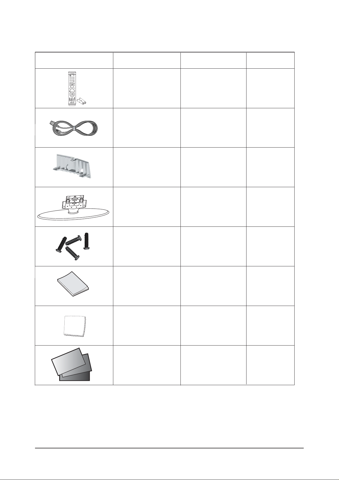
Item Item Name
Remote Control &
Batteries (AAA x 2)
Power Cord
Cover-Bottom
Stand
Stand Screw (4 ea)
Owner's Instructions
Cleaning Cloth
Warranty Card /
Registration
Card /Safety Guide Manual
(Not available in all locations)
32" : BN59-00511A &
4301-000121
40"/46" : BN59-00511A
32" : 3903-000144
40"/46" : 3903-000144
32" : BN63-01947A
40"/46" : BN63-01938A
32" : BN90-00828B
40"/46" : BN90-00821B
32" : 6002-001294
40"/46" : 6002-001294
32" : BN68-01001D
40"/46" : BN68-01001B
32" : BN63-01798A
40"/46" : BN63-07198A
BN68-00860A
Code.No Remark
2-3 Option Specification
Page 16

3 Alignments and Adjustments
3-1
3 Alignments and Adjustments
3-1 General Alignment Instuction
1. Usually, a color LCD-TV needs only slight touch-up adjustment upon installation.
Check the basic characteristics such as height, horizontal and vertical sync.
2. Use the specified test equipment or its equivalent.
3. Correct impedance matching is essential.
4. Avoid overload. Excessive signal from a sweep generator might overload the front-end
of the TV. When inserting signal markers, do not allow the marker generator to distort test result.
5. Connect the TV only to an AC power source with voltage and frequency as specified on
the backcover nameplate.
6. Do not attempt to connect or disconnect any wire while the TV is turned on. Make sure
that the power cord is disconnected before replacing any parts.
7. To protect aganist shock hazard, use an isolation transform.
Page 17
3 Alignments and Adjustments
3-2
3-2 Factory Mode Adjustments
3-2-1 Entering Factory Mode
To enter 'Service Mode' Press the remote -control keys in this sequence :
- If you do not have Factory remote - control
3-2-2 How to Access Service Mode
¡áUsing the Customer Remote
1.Turn the power off and set to stand-by mode
2.Press the remote buttons in this order; POWER OFF-MUTE-1-8-2-POWER ON to turn the set on.
3.The set turns on and enters service mode.
4.Press the Power button to exit and store data in memory.
¡ØIf you fail to enter service mode, repeat steps 1 and 2 above.
5.Initial SERVICE MODE DISPLAY State
Power OFF 1 8 2 Power OnMUTE
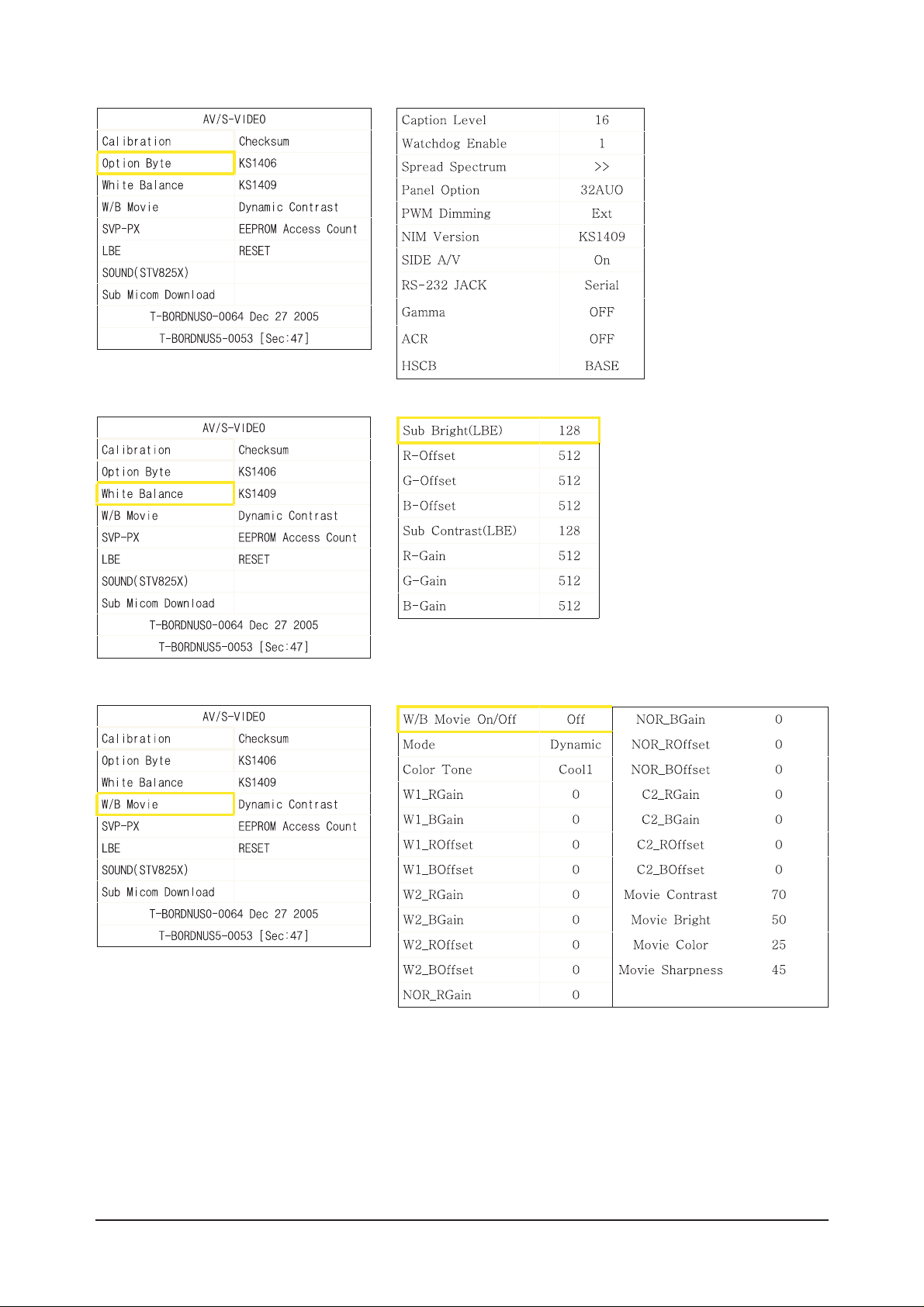
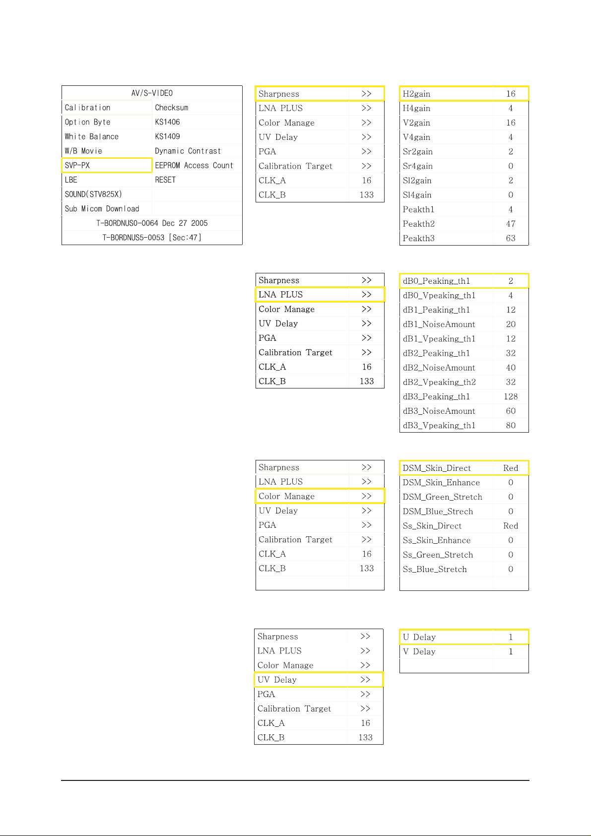
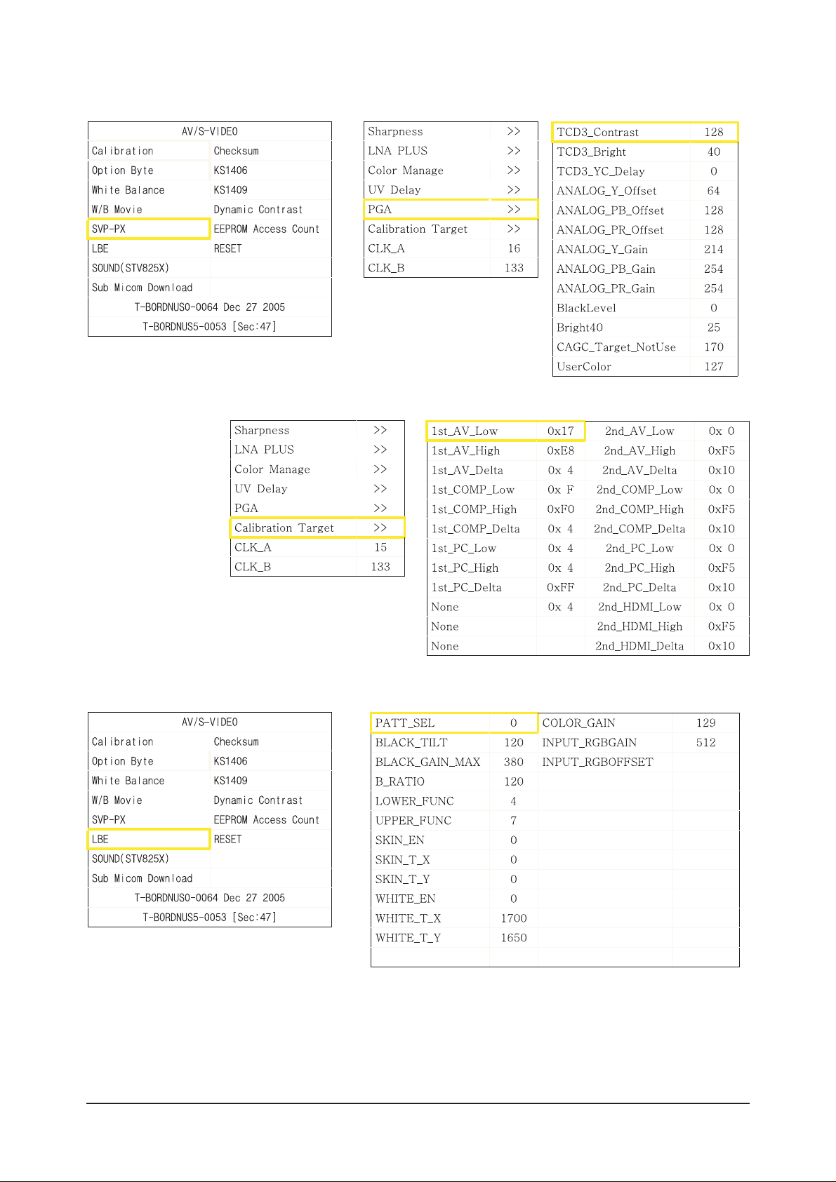
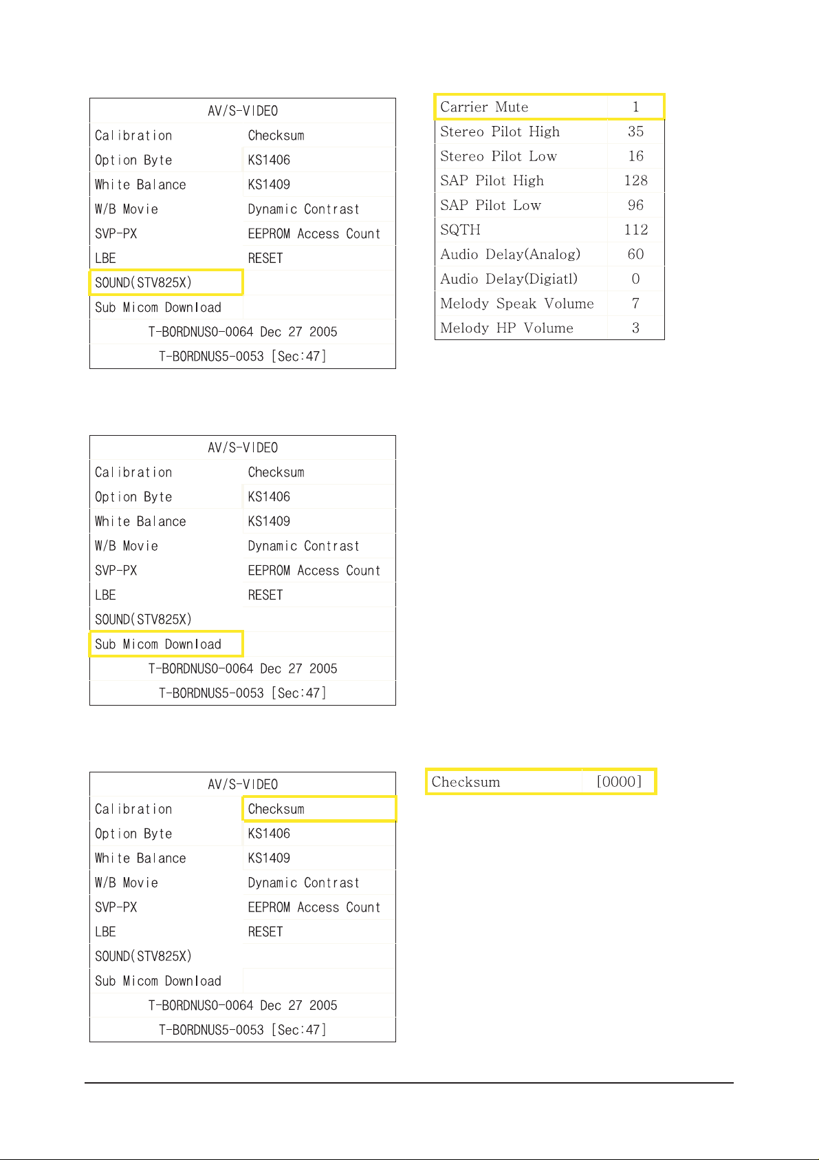
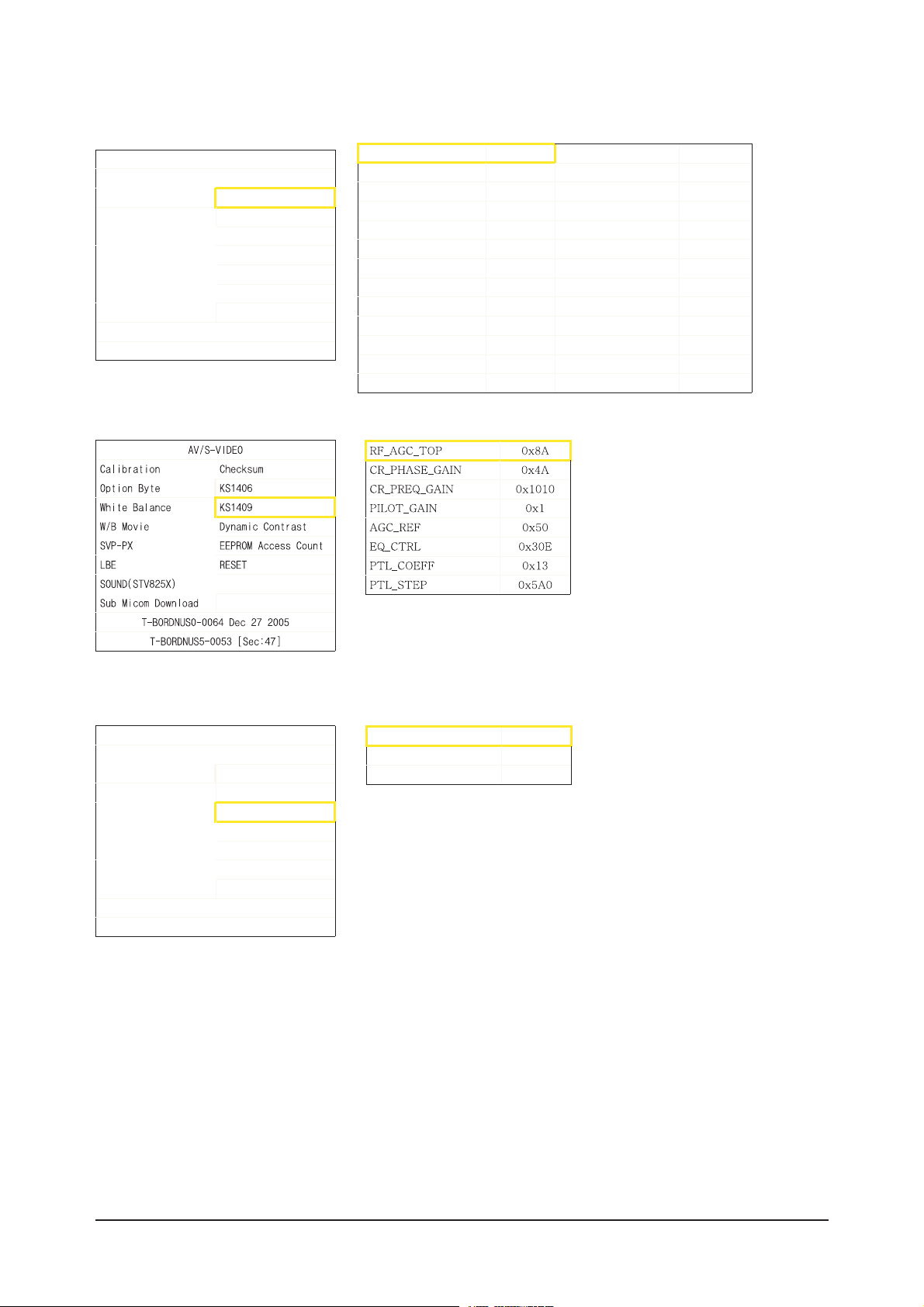
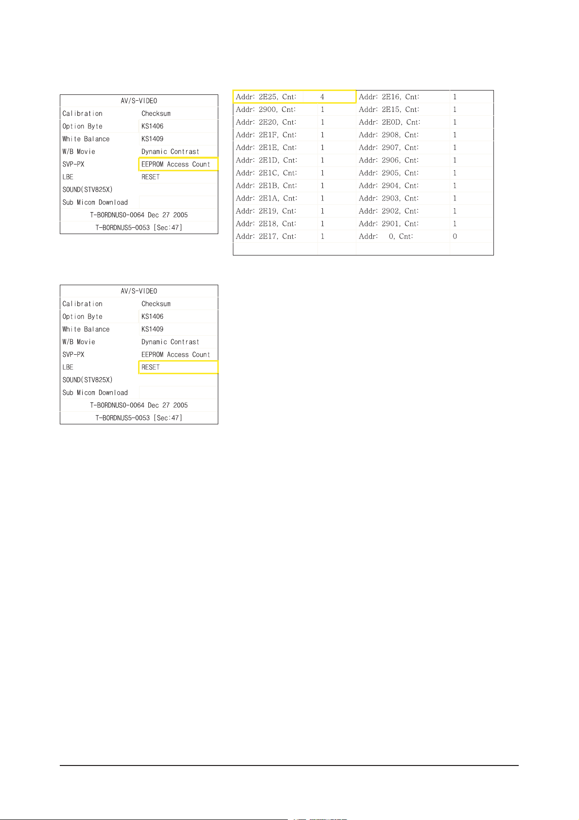
3-2-3 Factory Data
Page 18
3 Alignments and Adjustments
3-3
Page 19
3 Alignments and Adjustments
3-4
Page 20
3 Alignments and Adjustments
3-5
Page 21
3 Alignments and Adjustments
3-6
Page 22
3 Alignments and Adjustments
3-7
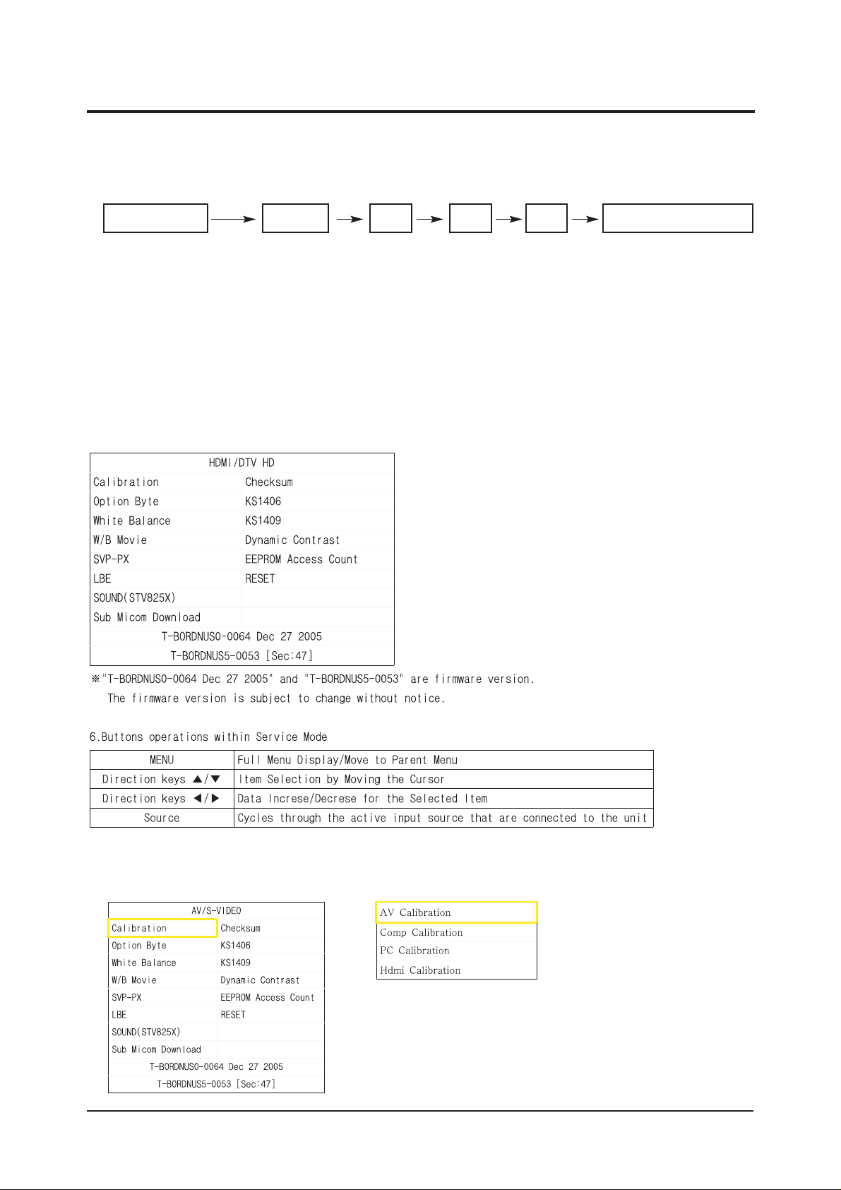
AV/ S-VI DEO
Cal i brat i on Checksum
Option Byte KS1406
Whi t e Ba l ance KS1409
W/BMovi e Dynamic Contrast
SVP-PX EEPROMAccess Count
LBE RESET
SOUND(STV8 2 5 X)
Sub MicomDownl oad
T-BORDNUS0-0064 Dec 27 2005
T-BORDNUS5-0053 [ Sec : 47
]
AGC_REF[AIR] 0x50 PACKET_ERR_ THR 0x8
CR_F_GAIN[AIR] 0xD0B
CR_L_GAIN[AIR] 0x24
EQ_STEP[AIR] 0xB
PILOT_GAIN[AIR] 0x1612
AGC_REF[CABLE] 0x50
CR_F_GAIN[CABLE] 0xD0B
CR_L_GAIN[CABLE] 0x24
EQ_STEP[CABLE] 0xB
PILOT_GAIN[CABLE] 0x1
CR_F2_GAIN[CABLE] 0x1612
AV/ S-VI DEO
Cal i br at i on Checksum
Option Byte KS1406
Whi t e Bal anc e KS1409
W/B Movi e Dynamic Contrast
SVP-PX EEPROMAccess Count
LBE RESET
SOUND(STV8 2 5 X)
Sub MicomDownl oad
T-BORDNUS0-0064 Dec 27 2005
T-BORDNUS5-0053 [ Sec : 47
]
Dynamic CE On
Dynamic Dimming On
LBE Y_MEAN READ
Page 23
3 Alignments and Adjustments
3-8
Page 24
3 Alignments and Adjustments
3-9
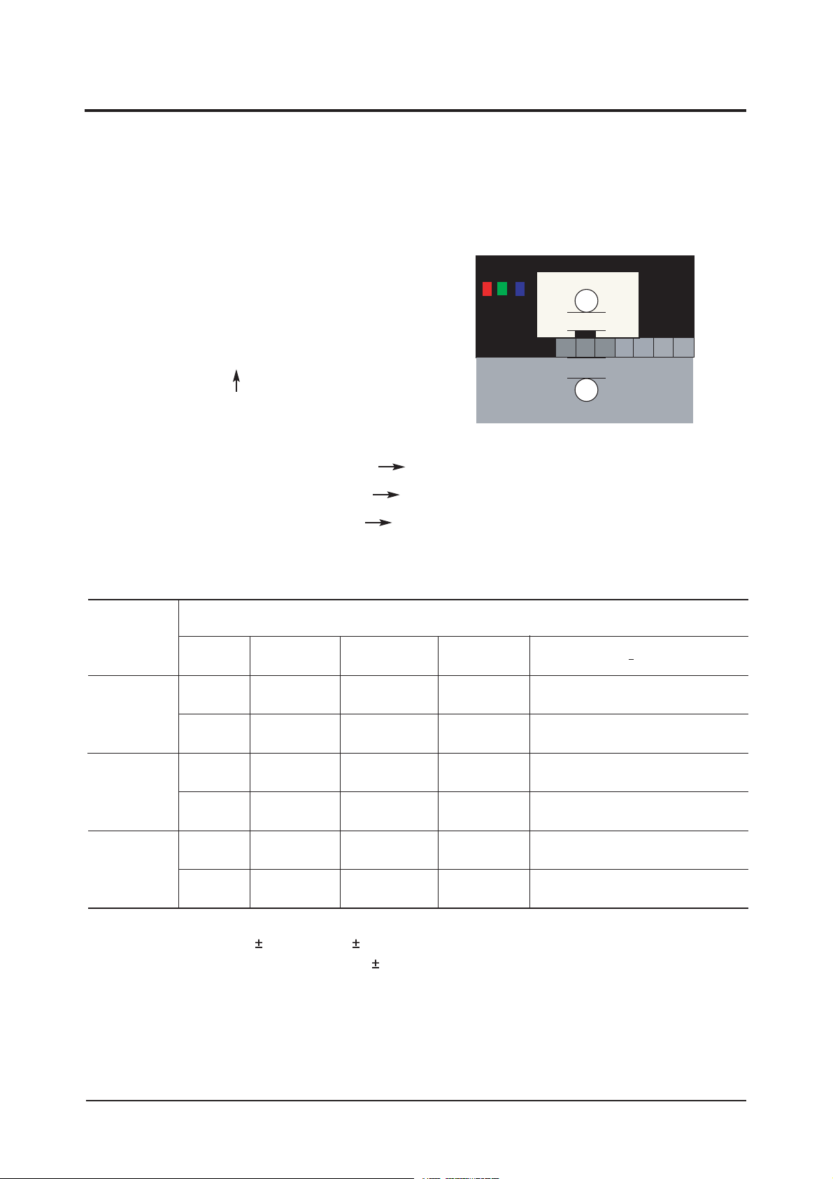
3-3 White Balance - Calibr ation
3-3-2 White Balance - Adjustment
3-3-1 White Balance -Calibration
3-3-3 Conditions for Measurement
1. Calibration
DTV Calibration
PC Calibration
(Calibration Condition refer to next page)
3. W/B
(low light) (hight light)
1. On the basis of toshiba ABL pattern : High Light level (57 IRE)
- INPUT SIGNAL GENERATOR : MSPG-925LTH
* Mode NO 1 : 744X484@60 Hz
NO 6 : 1280X720@60 Hz (Component 720P)
NO 21 : 1024X768@60 Hz
*
Pattern
NO 15 : Color bar
NO 16 : Toshiba ABL Pattern
NO 17 : 16 gray
2. Optical measuring device : CA210 (FL)
Please use the MSPG-925 LTH generator for model LN-S4092D, LN-S4692D, LN46M52BD.
(W/B adjustment Condition refer next page)
Sub Bright Sub Contrast
R offset R gain
G offset G gain
B offset B gain
Page 25
3 Alignments and Adjustments
3-10
3-4 White Ratio (Balance) Adjustment
1. You can adjust the white ratio in factory mode (1:Calibration, 3:White-Balance).
2. Since the adjustment value and the data value vary depending on the input source, you have to
adjust these in CVBS, Component 1 and HDMI 1 modes.
3. The optimal values for each mode are configured by default. (Refer to Table 1, 2.)
It varies with Panel's size and Specification.
- Equipment : CS-1000
- Pattern: Master MSPG925 #16 "ABL Pattern" as standard
- Use other equipment only after comparing the result
with that of the Master equipment.
- Set Aging time : 30min
- Calibration and Manual setting for WB adjustment.
HDMI: No Calibration Manual adjustment at #16 pattern (720p)
COMP: Calibration at #24 Chessboard Pattern Manual adjustment at #16 pattern (720p)
CVBS: Calibration at #24 Chessboard Pattern Manual adjustment at #16 pattern (NTSC)
PC : Calibration at #24 Chessboard Pattern No Manual adjustment (1024x768@60Hz)
CVBS
L/L
L/L
H/L
L/L
H/L
L/L
T(K) + MPCD
Y (cd/m
2
)
-
-
3.8(1.1Ft)
4.2(1.2Ft)
-
4.2(1.2Ft)
y
263
263
263
263
263
263
Adjustment Coordinate
x
263
263
263
263
263
263
15000K/0
15000K/0
15000K/0
15000K/0
15000K/0
15000K/0
Component
(720p)
HDMI
(1080i)
-White Balance Manual Adjustment (ABL Pattern)
-Adjustment Specification
White Balance : High light ( 2), Low light ( 3)
Luminance : High light (Don't care), Low light ( 0.2 Ft/L)
20mm
20mm
Page 26
3 Alignments and Adjustments
3-11
3-5 Ser vicing Infor mation
3-5-1 USB Download Method
1. Downloading boot code
Change the boot code's file name into "boot.bin".
Copy the "boot.bin" into the path "/bordeaux/us" in USB flash driver.
Turn off LCD TV.
Insert the USB flash driver into the service 1 jack of LCD TV.
Turn on LCD TV.
The banner osd "Updating SW..." is displayed.
The banner osd "Completed..." is displayed when the updating is completed.
Turn off and remove the USB flash driver from LCD TV
Check the program version.
2. Downloading application code
Change the application code's file name into "appl.rom".
Copy the "appl.rom" into the path "/bordeaux/us" in USB flash driver.
Turn off LCD TV.
Insert the USB flash driver into the service 1 jack of LCD TV.
Turn on LCD TV.
The banner osd "Updating SW..." is displayed.
The banner osd "Completed..." is displayed when the updating is completed.
Turn off and remove the USB flash driver from LCD TV
Check the program version.
Page 27

3 Alignments and Adjustments
3-12
Memo
Page 28
4 Troubleshooting
4-1
4 Troubleshooting
4-1 No Power
Does proper Stand-By DC A6.2V
appear at C156 ?
Change the Main Power Ass'y
32" : BN96-03057A
40" : BN63-01649A
46" : BN63-02062A
Yes
Yes
Yes
No
Check a connection power cable.
P/N: BN39-00691B
No
Does proper Main DC
B12V,B5V,B12VS appear at
C106, C115, C119?
Yes
No
No
Does proper Inverter DC
24V appear at CNM802,
CNM803 in SMPS?
Check IC106, IC107
Change the Main Ass'y
BN94-00850A
Yes
Does proper DC A5V,A3.3V
appear at C154, C151 ?
Check
IC101, IC102, IC103, IC104, IC105
Change the Main Ass'y BN94-00850A
Yes
Yes
Yes
Yes
Does proper DC
B9V,B8V,VCC5P,B3.3V_1,B3.3V_2,
B5V_VCC appear at C108, C110,
C123, C128, C135, C133 ?
Does proper DC 1.8V appear at
C1103, C1154, C364, C1011 ?
Does proper DC 2.5V appear at
C1214, C1746 ?
A power is supplied to set ?
Check a other function (No picture part)
Replace a LCD Panel
32": BN07-00324A
40" : BN07-00245A
46" : BN07-00282A
No
No
Check IC1101, IC1102, IC304, IC1001
Change the Main Ass'y BN94-00850A
No
No
Check IC1201, IC1702
Change the Main Ass'y BN94-00850A
No
LAMP Off, power indicator LED
red color ?
Page 29
4 Troubleshooting
4-2
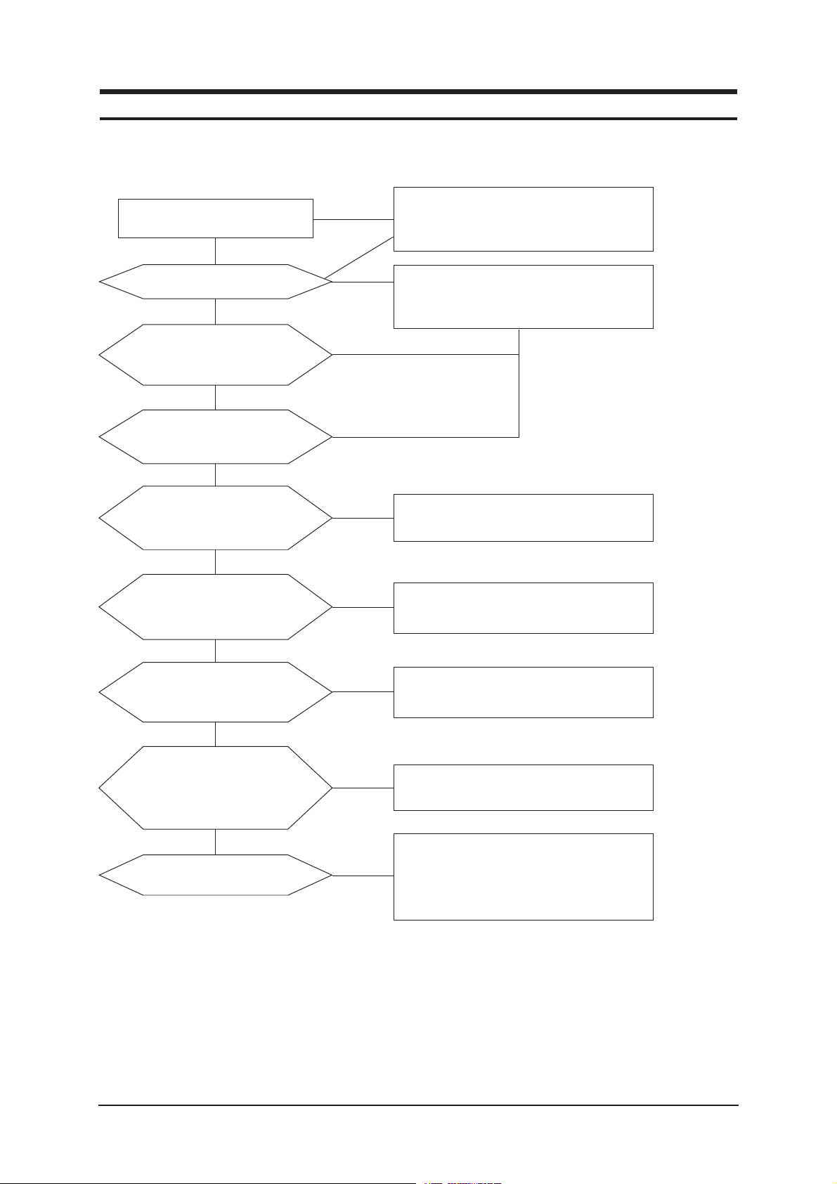
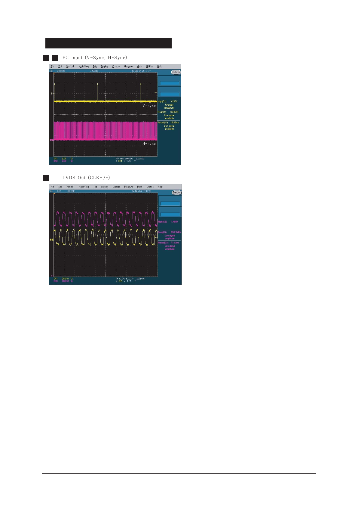
4-2 No Video (Analog PC Signal)
Check a PC source and
check the connection of
DSUB?
Input a analog PC signal.
Check a connected cable.
Yes
Does the signal appear at
#30,#22,#38,#41,#42
(R,G,B,H,V) of IC901?
Check JA801, PC cable.
Change a PC cable. Change a main
PCB ass'y
Yes
Does the digital data appear at
output of R1034~7, R1039?
Check IC901
Change a main PCB ass'y
Yes
Does the digital data
appear at output of
R1010~5, R1024~7?
Check IC1002
Change a main PCB ass'y
Yes
Check a LVDS cable?
Replace a LCD panel?
Please, Call to Samsung Co. LTD
Yes
Power Indicator is off.
Lamp on, no video
No
No
No
No
No
1
2
3
Page 30
4 Troubleshooting
4-3
WAVEFORMS
1 2
3
Page 31

4 Troubleshooting
4-4
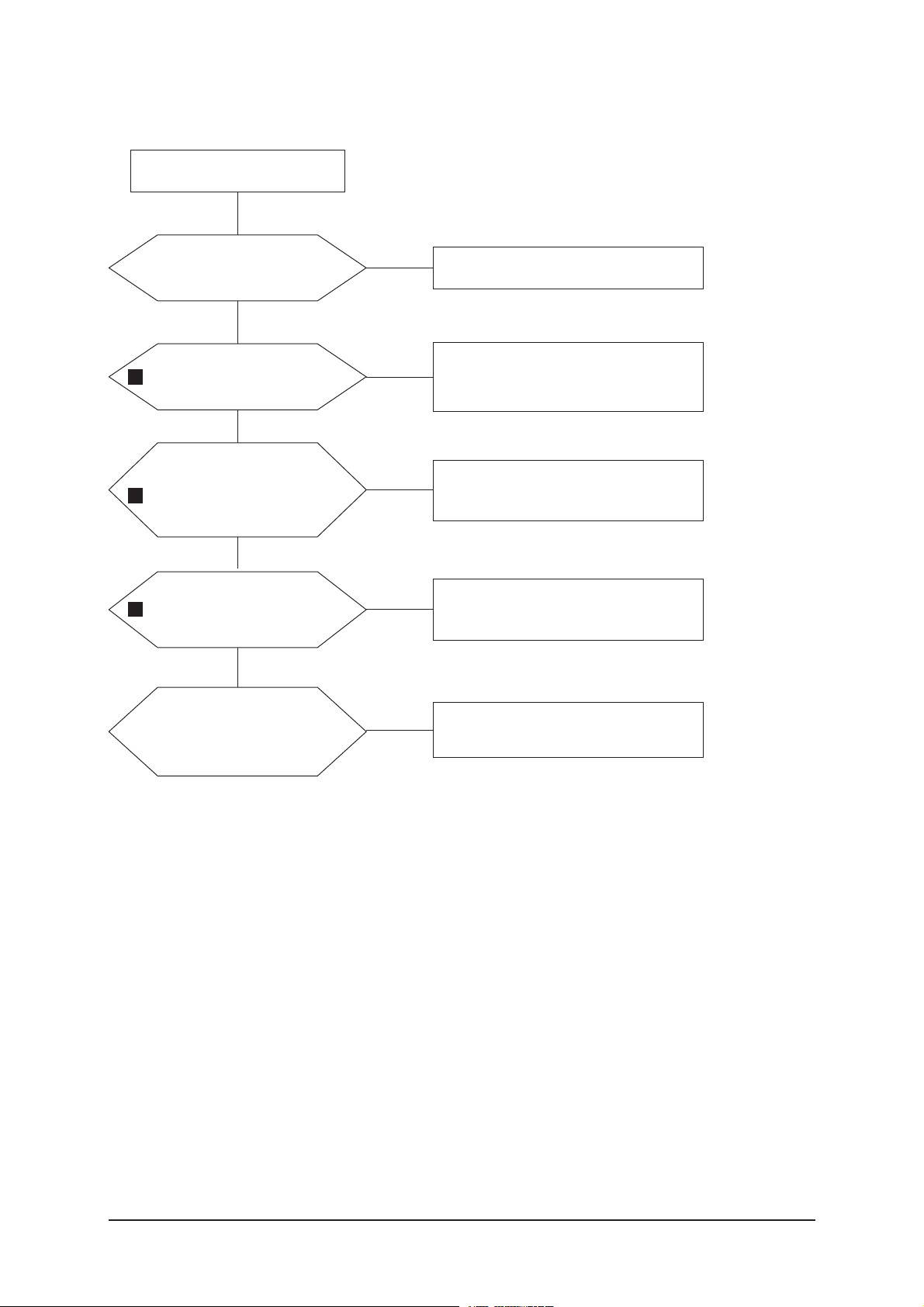
4-3 No Video (HDMI - Digital Signal)
Check a HDMI source and
check the connection of
HDMI cable?
Input a HDMI signal.
Check a connected cable.
Yes
Does the signal appear at
R874,R876,R878,R879,R88
2,R883,R886-R891(Data),
R884-5,R892-3(Clk+/-) ?
Check JA802, JA804, HDMI cable.
Change a HDMI cable. Change a
main PCB ass'y
Yes
Does the digital data
appear at output of
R901-8 ?
Check IC805
Change a main PCB ass'y
Yes
Does the digital data
appear at output of R1034-
7, R1039 ?
Check IC901
Change a main PCB ass'y
Yes
Does the digital data
appear at output of R1010-
5, R1024-7 ?
Check IC1002
Change a main PCB ass'y
Yes
Check a LVDS cable ?
Replace a LCD panel ?
Yes
Power Indicator is off.
Lamp on, no video.
No
No
No
No
No
Please, Call to Samsung Co. LTD.
No
4
5
6
7
Page 32

4 Troubleshooting
4-5
WAVEFORMS
4 5
Page 33

4 Troubleshooting
4-6
4-4 No Picture (Tuner_CVBS)
Check a RF source and
check the connection of RF
cable ?
Input a RF signal.
Check a connected cable.
Yes
Does the signal appear at
the main splitter cable ?
Check CN501.
Check splitter cable connection.
Change a main PCB ass'y or splitter
cable.
Yes
Does the signal appear at
C912 ?
Check TU501.
Change a main PCB ass'y or tuner.
Yes
Does the digital data
appear at output of
R1034-7, R1039 ?
Check IC901
Change a main PCB ass'y
Yes
Does the digital data
appear at output of R1010-
5, R1024-7 ?
Check IC1002
Change a main PCB ass'y
Yes
Check a LVDS cable ?
Replace a LCD panel ?
Yes
Power Indicator is off.
Lamp on, no picture.
No
No
No
No
No
Please, Call to Samsung Co. LTD.
No
8
9
10
Page 34

4 Troubleshooting
4-7
WAVEFORMS
6
Page 35

4 Troubleshooting
4-8
4-5 No Picture (Tuner DTV TS)
Check a RF source and
check the connection of RF
cable?
Input a RF signal.
Check a connected cable.
Yes
Check a RF source and
check the connection of
RF cable ?
Check CN501.
Check splitter cable connection.
Change a main PCB ass'y or splitter
cable.
Yes
Does the digital data appear at
RA501, RA502 (TS data) and
RA503(sync,valid,clock)
Check TU501.
Change a main PCB ass'y or tuner.
Yes
Does the digital data
appear at output of RA1401-
4(Y/CbCr) and
R1411,R1413,R1415(CLK,H,V) ?
Check IC1301
Change a main PCB ass'y
Yes
Does the digital data appear
at output of R1034-7,
R1039 ?
Check IC901
Change a main PCB ass'y
Yes
Does the digital data appear
at output of R1010-5,
R1024-7 ?
Check IC1002
Change a main PCB ass'y
Yes
Power Indicator is off.
Lamp on, no picture.
No
No
No
No
No
No
Yes
Check a LVDS cable ?
Replace a LCD panel ?
Please, Call to Samsung Co. LTD.
No
7
8
2
3
Page 36

4 Troubleshooting
4-9
WAVEFORMS
7
8
Page 37

4 Troubleshooting
4-10
4-6 No Picture(Video CVBS)
Check a video source and
check the connection of
video cable?
Input a video signal.
Check a connected cable.
Yes
Does the signal appear at
C915 or C933 of IC5007 ?
Check JA602 or Side-AV
Change a main PCB ass'y or Side-
AV Ass'y
Yes
Does the digital data appear
at output of R1034-7,
R1039 ?
Check IC901
Change a main PCB ass'y
Yes
Does the digital data appear
at output of R1010-5,
R1024-7 ?
Check IC1002
Change a main PCB ass'y
Yes
Check a LVDS cable ?
Replace a LCD panel ?
Please, Call to Samsung Co. LTD.
Yes
Power Indicator is off.
Lamp on, no picture.
No
No
No
No
No
6
2
3
Page 38

4 Troubleshooting
4-11
4-7 No Picture(S-Video Y/C)
Check a video source and
check the connection of
s-video cable?
Input a video signal.
Check a connected cable.
Yes
Does the signal appear at
C928/C915,C921/C913(Y,
C) of IC901 ?
Check JA604 or Side-AV
Change a main PCB ass'y or Side-
AV Ass'y
Yes
Does the digital data
appear at output of
R1034-7, R1039 ?
Check IC901
Change a main PCB ass'y
Yes
Does the digital data
appear at output of
R1010-5, R1024-7 ?
Check IC1002
Change a main PCB ass'y
Yes
Check a LVDS cable ?
Replace a LCD panel ?
Please, Call to Samsung Co. LTD.
Yes
Power Indicator is off.
Lamp on, no picture.
No
No
No
No
No
9
2
3
Page 39

4 Troubleshooting
4-12
WAVEFORMS
9
Page 40

4 Troubleshooting
4-13
4-8 No Picture
(Component1, 2 : 480i, 480p, 720p, 1080i[ Y, Pb, Pr] )
Check component source
and check the connection of
component cable ?
Input acomponent signal.
Check a connected cable.
Yes
Does the signal appear at
C919, C931, C926
(Y,Pb,Pr) of IC901 ?
Check JA601
Change a main PCB ass'y
Yes
Does the digital data
appear at output of
R1034-7, R1039 ?
Check IC901
Change a main PCB ass'y
Yes
Does the digital data
appear at output of
R1010-5, R1024-7 ?
Check IC1002
Change a main PCB ass'y
Yes
Check a LVDS cable ?
Replace a LCD panel ?
Please, Call to Samsung Co. LTD.
Yes
Power Indicator is off.
Lamp on, no picture.
No
No
No
No
No
10
2
3
Page 41

4 Troubleshooting
4-14
WAVEFORMS
10
Page 42

4 Troubleshooting
4-15
Check a sound source and
check the connection of
sound cable ?
Input a sound signal.
Check a connected cable.
Yes
No
No
Does the signal appear at
#9,10(VIDEO1 L/R),
#14,15(VIDEO2 L/R),
#79,80(PC,COMP,DTV,DVI-L/R)
of IC302?
Check JA602, JA603, JA803,
JA805 or Side-AV.
Change a main PCB ass'y or side-
AV Ass'y
Yes
No
Does the digital data appear at
#60-3(Mclk,Sclk,LRclk,data)
of IC302 ?
Check IC302
Change a main PCB ass'y
Yes
Yes
Does the signal appear at
L405-8 (L/R output) ?
Replace the speaker ass'y ?
No
Check IC401
Change a main PCB ass'y
No
Please, Call to Samsung Co. LTD.
No
4-9 No Sound
Picture is display, no sound.
11
12
13
Page 43

4 Troubleshooting
4-16
WAVEFORMS
11
12
13
Page 44

5 Exploded View & Parts List
5-1
5 Exploded View and Parts List
- You can search for updated part codes through ITSELF web site.
URL : http://itself.sec.samsung.co.kr/
5-1 LN-S3292D Exploded View
T0003
T0023
T0175
M0215
M0014
T0447
T0175
T0175
M0452
T0279
M0013
T0159
M0013
Page 45

5 Exploded View & Parts List
5-2
5-2 LN-S3292D Parts list
Location Code.No Item & Specification Q'ty SA/SNA Remark
T0003 BN96-03941A ASSY COVER P-FRONT;MILANO-3,32UO,ABS,HB, 1 SNA
T0023 BN96-03425A ASSY COVER P-KNOB POWER;MILANO-3,46UO,AB 1 SNA
T0175 BN96-02190B ASSY SPEAKER P;8ohm,Left,10W,Milano 40 1 SA
T0175 BN96-02191B ASSY SPEAKER P;8ohm,Right,10W,Milano 40 1 SA
M0215 BN07-00324A LCD-PANEL;T315XW02(V3),8bit,760.0*450.0* 1 SA
T0447 BN96-03942A ASSY BRACKET P-PANEL;MILANO-3,32UO 1 SNA
M0014 BN94-01037A ASSY PCB MAIN;LNR3292DX/XAA 1 SNA
T0159 BN96-03775A ASSY PCB P-SMPS;FreeVoltage SMPS,LA32R71 1 SA
T0175 BN96-03987A ASSY SHIELD P-PCB MAIN;MILANO-3,32,SECC, 1 SNA
M0452 BN96-02438A ASSY COVER P-HOLDER AV;MILANO,32,57UO,AB 1 SA
T0279 BN63-02544A COVER-JACK;MILANO3 46,HIPS,V0,GR503 1 SNA
M0013 BN96-02205A ASSY COVER P-REAR;MILANO,32,HIPS,V0,GR50 1 SA
M0013 BN96-02840B ASSY STAND P-BASE;32 MILANO-2,SWIVEL,ABS 1 SA
Page 46

5 Exploded View & Parts List
5-3
5-3 LN-S4092D Exploded View
T0279
M0452
T0603
T0175
M0014
T0003
M0013
M0146
T0120
M0146
M0215
T0175
M0013
Page 47

5 Exploded View & Parts List
5-4
5-4 LN-S4092D Parts list
Location Code.No Item & Specification Q'ty SA/SNA Remark
T0003 BN96-03424A ASSY COVER P-FRONT;MILANO-3,40UO,ABS,HB, 1 SA
T0175 BN96-02190B ASSY SPEAKER P;8ohm,Left,10W,Milano 40 1 SA
T0175 BN96-02191B ASSY SPEAKER P;8ohm,Right,10W,Milano 40 1 SA
M0215 BN07-00245A LCD-PANEL;LTA400WS-LH1,8bit,952*551*51.0 1 SA
M0146 BN61-01503A BRACKET-PANEL TOP;40" ROME,SECC,T1.2 1 SNA
T0120 BN94-00622E ASSY PCB POWER;ROME,40",AC110V,USA,JAPAN 1 SA
M0014 BN94-00963A ASSY PCB MAIN-SPZ;LNS4092WX/XAA,AM LCD 1 SA
M0146 BN63-01649A SHIELD-PCB SMPS;40" ROME,SECC,T0.5 1 SNA
T0603 BN63-02542A SHIELD-PCB MAIN;MILANO3 40,SECC,T0.5 1 SNA
M0452 BN96-02447A ASSY COVER P-HOLDER AV;MILANO,40,46UO,AB 1 SNA
T0279 BN63-02544A COVER-JACK;MILANO3 46,HIPS,V0,GR503 1 SNA
M0013 BN96-02348C ASSY COVER P-REAR;MILANO,40,HIPS,V0,GR50 1 SA
M0013 BN96-02841B ASSY STAND P-BASE;40 MILANO-2,SWIVEL,ABS 1 SA
Page 48

5 Exploded View & Parts List
5-5
5-5 LN-S4692D / LN46M52BD Exploded View
T0279
M0452
T0175
M0146
M0014
T0003
M0013
M0112
T0120
M0215
T0175
M0013
Page 49

5 Exploded View & Parts List
5-6
5-6 LN-S4692D / LN46M52BD Parts list
Location Code.No Item & Specification Q'ty SA/SNA Remark
T0003 BN96-03423A ASSY COVER P-FRONT;MILANO-3,46UO,ABS,HB, 1 S.A
T0175 BN96-02077C ASSY SPEAKER P;8ohm,Left,15W,200mm,Sanjo 1 S.A
T0175 BN96-02078C ASSY SPEAKER P;8ohm,Right,15W,550mm,Sanj 1 S.A
M0215 BN07-00282A LCD-PANEL;LTA460WS-LH1,8bit,1083*627*56. 1 S.A
M0146 BN61-01889A BRACKET-PANEL TOP;46 MILANO,SECC,T1.6 1 S.N.A
T0120 BN97-00964B ASSY SMD-AM LCD;LNS4692WX/XAA 1 S.N.A
M0014 BN94-00963B ASSY PCB MAIN-SPZ;LNS4692WX/XAA,AM LCD 1 S.A
M0112 BN63-01829G COVER-FRONT;MILANO-3,46UO,ABS,HB,BK23,ST 1 S.N.A
M0452 BN96-02447A ASSY COVER P-HOLDER AV;MILANO,40,46UO,AB 1 S.N.A
T0279 BN63-02544A COVER-JACK;MILANO3 46,HIPS,V0,GR503 1 S.N.A
M0013 BN96-03427A ASSY STAND P-BASE;MILANO-3,46,SWIVEL,ABS 1 S.A
M0013 BN96-02200D ASSY COVER P-REAR;46 MILANO,HIPS,V0,GR50 1 S.A
Page 50

6 Electrical Parts List
6-1
Level Loc. No. Code No. Description & Specification Q'ty SA/SNA
LNS3292DX/XAA LN-S3292D,E62A/32M50-GMO,32,LCD-TV,UNITE
0.1 M0216 BN90-00828B ASSY STAND;32,MILANO-2,SWIVEL,ABS,HB,BK0 1 S.N.A
..2 T0524 6902-000520 BAG PE;HDPE/NITRON(DOUBLE),T0.015/T0.5(D 1 S.N.A
..2 M0013 BN96-02840B ASSY STAND P-BASE;32 MILANO-2,SWIVEL,ABS 1 S.A
...3 T0081 6002-001294 SCREW-TAPPING;BH,+,,M4,L16,ZPC(BLK) 4 S.A
...3 M0081 6003-001239 SCREW-TAPTITE;FH,+,B,M4,L10,ZPC(YEL),SWR 6 S.A
...3 BN61-02149A HOLDER-SWIVEL RING;32 MILANO,ACETAL(AL), 1 S.N.A
...3 BN61-02151A HOLDER-SWIVEL RING;32 MILANO,ACETAL(AL), 1 S.N.A
...3 BN61-02154A BRACKET GUIDE;32 MILANO,SECC,T1.6,SUB 1 S.N.A
...3 BN61-02156A BRACKET-STAND BOTTOM;32 MILANO,SECC,T2.0 1 S.N.A
...3 BN61-02157A GUIDE-STAND;32 MILANO,SWIVEL,ABS,HB,GR50 1 S.N.A
...3 M0111 BN63-02276B COVER-STAND;32 MILANO-2,SWIVEL,ABS,HB,BK 1 S.N.A
...3 T0132 BN73-00052A RUBBER FOOT;ARES 17,SILICON,DIA 17 * T1. 8 S.N.A
...3 CCM1 BN63-02864A COVER-SHEET;BORDEAUX32,PVC MILAY,T0.15,S 1 S.A
...3 CCM1 BN63-02865A COVER-SHEET;BORDEAUX32,PVC MILAY,T0.15,S 1 S.A
0.1 M0001 BN90-01003A ASSY COVER FRONT;32M50,UO,ABS,HB,BK23,MI 1 S.N.A
..2 M0081 6003-001003 SCREW-TAPTITE;BH,+,B,M4,L12,ZPC(BLK),SWR 1 S.N.A
..2 M0081 6006-001096 SCREW-TAPTITE;BH,+,WP,B,M4.0,L12,ZPC(BLK 6 S.N.A
..2 T0023 BN96-03425A ASSY COVER P-KNOB POWER;MILANO-3,46UO,AB 1 S.N.A
...3 T0081 BN61-02466A GUIDE-POWER;MILANO 3,PMMA 1 S.N.A
...3 T0023 BN64-00488A KNOB-POWER;MILANO-3,ABS,V0,BK07,H/STAMPI 1 S.N.A
...3 T0054 BN64-00489A KNOB-DECORATION;MILANO3,ABS,HB,AL 1 S.N.A
...3 CIS7 AA61-60003B SPRING ETC-CS;-,SUS304,-,-,OD11.2,N7,OD1 1 S.N.A
..2 T0003 BN96-03941A ASSY COVER P-FRONT;MILANO-3,32UO,ABS,HB, 1 S.A
...3 M0081 6003-001003 SCREW-TAPTITE;BH,+,B,M4,L12,ZPC(BLK),SWR 4 S.N.A
...3 M0081 6003-001003 SCREW-TAPTITE;BH,+,B,M4,L12,ZPC(BLK),SWR 2 S.N.A
...3 M0162 6502-001067 CABLE CLAMP;DAFC-1300,ID2.2,T5.2,NYLIN6/ 1 S.N.A
...3 M0112 BN63-01934F COVER-FRONT;MILANO-3,32UO,ABS,HB,BK23,S/ 1 S.N.A
...3 T0069 BN63-01935A COVER-MIDDLE;MILANO,32,ABS,V0,GR70,SV012 1 S.N.A
...3 CCM1 BN63-02183F COVER-SHEET;Rhcm,PE Vinyl,T0.05,900mm,20 1.48 S.N.A
...3 T0056 BN63-02786A COVER-DECORATION;MILANO3-32,ABS,-,-,-,V0 1 S.N.A
...3 T0061 BN64-00343A WINDOW-REMOCON;ROME,40,PC,CLEAR 1 S.N.A
...3 T0022 BN64-00490A KNOB-CONTROL;MILANO-3,40,46,ABS,V0 1 S.N.A
...3 M0146 BN96-02399A ASSY BOARD P-POWER & IR;LNR269DX/XAA,CT5 1 S.A
...3 M0145 BN96-02400A ASSY BOARD P-FUNCTION;LNR269DX/XAA,CT500 1 S.A
...3 T0382 BP61-00509C HOLDER-CARE;PJT,ACRYL-FOAM,T0.25,W20.0mm 0.28 S.N.A
..2 T0382 BP61-00495C HOLDER-CARE;PJT,ACRYL-FOAM,T0.25,W30.0mm 0.2 S.N.A
..2 T0175 BN96-02190A ASSY SPEAKER P;8ohm,Left,10W,Milano 32/4 1 S.A
..2 T0175 BN96-02191A ASSY SPEAKER P;8ohm,Right,10W,Milano 32/ 1 S.A
0.1 M0002 BN90-01021A ASSY COVER REAR;32M50,UO,HIPS,V0,GR503,M 1 S.N.A
..2 T0081 6002-001294 SCREW-TAPPING;BH,+,,M4,L16,ZPC(BLK) 10 S.A
..2 M0081 6003-000115 SCREW-TAPTITE;BH,+,B,M3,L6,ZPC(BLK),SWRC 3 S.A
..2 T0279 BN63-02544A COVER-JACK;MILANO3 46,HIPS,V0,GR503 1 S.N.A
..2 M0013 BN96-02205A ASSY COVER P-REAR;MILANO,32,HIPS,V0,GR50 1 S.A
...3 M0081 6003-001003 SCREW-TAPTITE;BH,+,B,M4,L12,ZPC(BLK),SWR 2 S.N.A
...3 M0081 6003-001321 SCREW-TAPTITE;BH,+,B,M4,L8,ZPC(BLK),SWRC 4 S.A
...3 M0114 BN61-01605A HOLDER-WIRE;FIRENZE 46,HIPS HB,GR503 1 S.N.A
...3 M0006 BN63-01936A COVER-REAR;MILANO,32,HIPS,V0,GR503 1 S.N.A
...3 BN96-03594A ASSY BRACKET P-VESA;MILANO,32,BR/VESA+BR 1 S.N.A
....4 M0113 BN61-01505A BRACKET-VESA;40,ROME,SECC,T1.6 1 S.N.A
....4 T0101 BN61-02499A BRACKET-WALL;GML32KE,SECC,T1.0 1 S.N.A
6 Electrical Parts List
You can search for updated part codes through ITSELF web site.
URL : http://itself.sec.samsung.co.kr/
6-1 LNS3292D Parts List
Page 51

6 Electrical Parts List
6-2
Level Loc. No. Code No. Description & Specification Q'ty SA/SNA
0.1 MP1.0 BN91-01058T ASSY LCD-AMZ;LE32M61BX/XEC 1 S.N.A
..2 M0215 BN07-00324A LCD-PANEL;T315XW02(V3),8bit,760.0*450.0* 1 S.A
0.1 M0017 BN91-01126A ASSY CHASSIS;LNR3292DX/XAA 1 S.N.A
..2 M0014 BN94-01037A ASSY PCB MAIN;LNR3292DX/XAA 1 S.A
...3 T0245 0202-001522 SOLDER-WIRE FLUX;LFA3-107,-,D1.2,96.5Sn/ 0.25 S.N.A
...3 JA801 3701-001294 CONNECTOR-DSUB;15P,3R,FEMALE,STRAIGHT,AU 1 S.A
...3 CN330 3711-004484 HEADER-BOARD TO CABLE;BOX,5P,1R,2mm,STRA 1 S.A
...3 CN330 3711-004909 HEADER-BOARD TO CABLE;BOX,14P,2R,2MM,ANG 1 S.A
...3 CN1003 3711-005884 HEADER-BOARD TO BOARD;BOX,30P,2R,2mm,ANG 1 S.A
...3 CN330 3711-005942 HEADER-BOARD TO CABLE;BOX,16P,1R,2mm,STR 1 S.A
...3 JA330 3722-001061 JACK-PHONE;1P,3.6PI,AG,BLK,N 1 S.A
...3 JA330 3722-001061 JACK-PHONE;1P,3.6PI,AG,BLK,N 1 S.A
...3 CN1301 3722-001147 JACK-USB;4P/1C,AU,BLK,STRAIGHT,A TYPE 1 S.A
...3 JA332 3722-001734 JACK-VHS;4P,SN,BLK,STRAIGHT 1 S.A
...3 JA333 3722-001903 JACK-PIN;2P,-,AU,WHT/RED,- 1 S.A
...3 JA333 3722-001903 JACK-PIN;2P,-,AU,WHT/RED,- 1 S.A
...3 JA333 3722-001903 JACK-PIN;2P,-,AU,WHT/RED,- 1 S.A
...3 JA333 3722-001938 JACK-PIN;3P,-,AU,GRN/BLU/RED,- 1 S.A
...3 JA333 3722-002063 JACK-PIN;3P,AU,YEL/WHT/RED,STRAIGHT 1 S.A
...3 CIS3 BN40-00081A TUNER;DNVS303HH261A,DNVS303HH261A,VSB/QA 1 S.A
...3 T0253 BN59-00498A MODULE-SPLITTER;UMX-NT-059,UMX-NT-059,2i 1 S.A
...3 T0530 BN61-01521A SUPPORT-PCB;ROME,SPTE,T0.5,L11.0 1 S.N.A
...3 T0530 BN61-01521A SUPPORT-PCB;ROME,SPTE,T0.5,L11.0 1 S.N.A
...3 T0530 BN61-01521A SUPPORT-PCB;ROME,SPTE,T0.5,L11.0 1 S.N.A
...3 T0852 BN96-01470A ASSY BOARD P-OPTICAL;HP-P5581,OPTICAL 1 S.A
....4 CN906 3707-001067 CONNECTOR-OPTICAL;PLUG,SM,-,4.4/2.0mm 1 S.A
...3 T0174 BN97-01099A ASSY SMD;LNR3292DX/XAA 1 S.N.A
....4 CIS05 0202-001477 SOLDER-CREAM;LST309-M,-,D20~45§-,96.5Sn/ 4.902 S.N.A
....4 D501 0401-001056 DIODE-SWITCHING;MMBD4148SE,100V,200mA,SO 1 S.A
....4 D708 0401-001056 DIODE-SWITCHING;MMBD4148SE,100V,200mA,SO 1 S.A
....4 D709 0401-001056 DIODE-SWITCHING;MMBD4148SE,100V,200mA,SO 1 S.A
....4 D710 0401-001056 DIODE-SWITCHING;MMBD4148SE,100V,200mA,SO 1 S.A
....4 D711 0401-001056 DIODE-SWITCHING;MMBD4148SE,100V,200mA,SO 1 S.A
....4 D712 0401-001056 DIODE-SWITCHING;MMBD4148SE,100V,200mA,SO 1 S.A
....4 D713 0401-001056 DIODE-SWITCHING;MMBD4148SE,100V,200mA,SO 1 S.A
....4 D801 0401-001056 DIODE-SWITCHING;MMBD4148SE,100V,200mA,SO 1 S.A
....4 D802 0401-001056 DIODE-SWITCHING;MMBD4148SE,100V,200mA,SO 1 S.A
....4 D803 0401-001056 DIODE-SWITCHING;MMBD4148SE,100V,200mA,SO 1 S.A
....4 D813 0401-001056 DIODE-SWITCHING;MMBD4148SE,100V,200mA,SO 1 S.A
....4 D814 0401-001056 DIODE-SWITCHING;MMBD4148SE,100V,200mA,SO 1 S.A
....4 D815 0401-001056 DIODE-SWITCHING;MMBD4148SE,100V,200mA,SO 1 S.A
....4 D816 0401-001056 DIODE-SWITCHING;MMBD4148SE,100V,200mA,SO 1 S.A
....4 D817 0401-001056 DIODE-SWITCHING;MMBD4148SE,100V,200mA,SO 1 S.A
....4 D818 0401-001056 DIODE-SWITCHING;MMBD4148SE,100V,200mA,SO 1 S.A
....4 D819 0401-001056 DIODE-SWITCHING;MMBD4148SE,100V,200mA,SO 1 S.A
....4 D820 0401-001056 DIODE-SWITCHING;MMBD4148SE,100V,200mA,SO 1 S.A
....4 D831 0401-001056 DIODE-SWITCHING;MMBD4148SE,100V,200mA,SO 1 S.A
....4 D832 0401-001056 DIODE-SWITCHING;MMBD4148SE,100V,200mA,SO 1 S.A
....4 D833 0401-001056 DIODE-SWITCHING;MMBD4148SE,100V,200mA,SO 1 S.A
....4 D834 0401-001056 DIODE-SWITCHING;MMBD4148SE,100V,200mA,SO 1 S.A
....4 D835 0401-001056 DIODE-SWITCHING;MMBD4148SE,100V,200mA,SO 1 S.A
....4 D836 0401-001056 DIODE-SWITCHING;MMBD4148SE,100V,200mA,SO 1 S.A
....4 D837 0401-001056 DIODE-SWITCHING;MMBD4148SE,100V,200mA,SO 1 S.A
....4 D838 0401-001056 DIODE-SWITCHING;MMBD4148SE,100V,200mA,SO 1 S.A
....4 D101 0402-000553 DIODE-SCHOTTKY;SS24/B240,40V,2000mA,DO-2 1 S.A
....4 D102 0402-000553 DIODE-SCHOTTKY;SS24/B240,40V,2000mA,DO-2 1 S.A
....4 D1301 0403-000620 DIODE-ZENER;RLZ5.6B,5.45-5.73V,500mW,LL- 1 S.A
....4 D1302 0403-000620 DIODE-ZENER;RLZ5.6B,5.45-5.73V,500mW,LL- 1 S.A
....4 D206 0403-000620 DIODE-ZENER;RLZ5.6B,5.45-5.73V,500mW,LL- 1 S.A
....4 D821 0403-000620 DIODE-ZENER;RLZ5.6B,5.45-5.73V,500mW,LL- 1 S.A
....4 D822 0403-000620 DIODE-ZENER;RLZ5.6B,5.45-5.73V,500mW,LL- 1 S.A
Page 52

6 Electrical Parts List
6-3
Level Loc. No. Code No. Description & Specification Q'ty SA/SNA
....4 D839 0403-000620 DIODE-ZENER;RLZ5.6B,5.45-5.73V,500mW,LL- 1 S.A
....4 D840 0403-000620 DIODE-ZENER;RLZ5.6B,5.45-5.73V,500mW,LL- 1 S.A
....4 D901 0403-000620 DIODE-ZENER;RLZ5.6B,5.45-5.73V,500mW,LL- 1 S.A
....4 D902 0403-000620 DIODE-ZENER;RLZ5.6B,5.45-5.73V,500mW,LL- 1 S.A
....4 D903 0403-000620 DIODE-ZENER;RLZ5.6B,5.45-5.73V,500mW,LL- 1 S.A
....4 D904 0403-000620 DIODE-ZENER;RLZ5.6B,5.45-5.73V,500mW,LL- 1 S.A
....4 D905 0403-000620 DIODE-ZENER;RLZ5.6B,5.45-5.73V,500mW,LL- 1 S.A
....4 D906 0403-000620 DIODE-ZENER;RLZ5.6B,5.45-5.73V,500mW,LL- 1 S.A
....4 D907 0403-000620 DIODE-ZENER;RLZ5.6B,5.45-5.73V,500mW,LL- 1 S.A
....4 D908 0403-000620 DIODE-ZENER;RLZ5.6B,5.45-5.73V,500mW,LL- 1 S.A
....4 D909 0403-000620 DIODE-ZENER;RLZ5.6B,5.45-5.73V,500mW,LL- 1 S.A
....4 D910 0403-000620 DIODE-ZENER;RLZ5.6B,5.45-5.73V,500mW,LL- 1 S.A
....4 D911 0403-000620 DIODE-ZENER;RLZ5.6B,5.45-5.73V,500mW,LL- 1 S.A
....4 D912 0403-000620 DIODE-ZENER;RLZ5.6B,5.45-5.73V,500mW,LL- 1 S.A
....4 D205 0403-001016 DIODE-ZENER;RLZ6.2B,5.96-6.27V,500mW,LL- 1 S.A
....4 D804 0403-001016 DIODE-ZENER;RLZ6.2B,5.96-6.27V,500mW,LL- 1 S.A
....4 D827 0403-001016 DIODE-ZENER;RLZ6.2B,5.96-6.27V,500mW,LL- 1 S.A
....4 D601 0403-001052 DIODE-ZENER;RD8.2MB,7.7-8.7V,200mW,SOT-2 1 S.A
....4 D602 0403-001052 DIODE-ZENER;RD8.2MB,7.7-8.7V,200mW,SOT-2 1 S.A
....4 D603 0403-001052 DIODE-ZENER;RD8.2MB,7.7-8.7V,200mW,SOT-2 1 S.A
....4 D604 0403-001052 DIODE-ZENER;RD8.2MB,7.7-8.7V,200mW,SOT-2 1 S.A
....4 D605 0403-001052 DIODE-ZENER;RD8.2MB,7.7-8.7V,200mW,SOT-2 1 S.A
....4 D606 0403-001052 DIODE-ZENER;RD8.2MB,7.7-8.7V,200mW,SOT-2 1 S.A
....4 D607 0403-001052 DIODE-ZENER;RD8.2MB,7.7-8.7V,200mW,SOT-2 1 S.A
....4 D608 0403-001052 DIODE-ZENER;RD8.2MB,7.7-8.7V,200mW,SOT-2 1 S.A
....4 D609 0403-001052 DIODE-ZENER;RD8.2MB,7.7-8.7V,200mW,SOT-2 1 S.A
....4 D610 0403-001052 DIODE-ZENER;RD8.2MB,7.7-8.7V,200mW,SOT-2 1 S.A
....4 D611 0403-001052 DIODE-ZENER;RD8.2MB,7.7-8.7V,200mW,SOT-2 1 S.A
....4 D612 0403-001052 DIODE-ZENER;RD8.2MB,7.7-8.7V,200mW,SOT-2 1 S.A
....4 D613 0403-001052 DIODE-ZENER;RD8.2MB,7.7-8.7V,200mW,SOT-2 1 S.A
....4 D614 0403-001052 DIODE-ZENER;RD8.2MB,7.7-8.7V,200mW,SOT-2 1 S.A
....4 D615 0403-001052 DIODE-ZENER;RD8.2MB,7.7-8.7V,200mW,SOT-2 1 S.A
....4 D616 0403-001052 DIODE-ZENER;RD8.2MB,7.7-8.7V,200mW,SOT-2 1 S.A
....4 D617 0403-001052 DIODE-ZENER;RD8.2MB,7.7-8.7V,200mW,SOT-2 1 S.A
....4 D618 0403-001052 DIODE-ZENER;RD8.2MB,7.7-8.7V,200mW,SOT-2 1 S.A
....4 D619 0403-001052 DIODE-ZENER;RD8.2MB,7.7-8.7V,200mW,SOT-2 1 S.A
....4 D620 0403-001052 DIODE-ZENER;RD8.2MB,7.7-8.7V,200mW,SOT-2 1 S.A
....4 D621 0403-001052 DIODE-ZENER;RD8.2MB,7.7-8.7V,200mW,SOT-2 1 S.A
....4 D622 0403-001052 DIODE-ZENER;RD8.2MB,7.7-8.7V,200mW,SOT-2 1 S.A
....4 D623 0403-001052 DIODE-ZENER;RD8.2MB,7.7-8.7V,200mW,SOT-2 1 S.A
....4 D624 0403-001052 DIODE-ZENER;RD8.2MB,7.7-8.7V,200mW,SOT-2 1 S.A
....4 D625 0403-001052 DIODE-ZENER;RD8.2MB,7.7-8.7V,200mW,SOT-2 1 S.A
....4 D626 0403-001052 DIODE-ZENER;RD8.2MB,7.7-8.7V,200mW,SOT-2 1 S.A
....4 D627 0403-001052 DIODE-ZENER;RD8.2MB,7.7-8.7V,200mW,SOT-2 1 S.A
....4 D805 0403-001052 DIODE-ZENER;RD8.2MB,7.7-8.7V,200mW,SOT-2 1 S.A
....4 D806 0403-001052 DIODE-ZENER;RD8.2MB,7.7-8.7V,200mW,SOT-2 1 S.A
....4 D807 0403-001052 DIODE-ZENER;RD8.2MB,7.7-8.7V,200mW,SOT-2 1 S.A
....4 D808 0403-001052 DIODE-ZENER;RD8.2MB,7.7-8.7V,200mW,SOT-2 1 S.A
....4 D809 0403-001052 DIODE-ZENER;RD8.2MB,7.7-8.7V,200mW,SOT-2 1 S.A
....4 D810 0403-001052 DIODE-ZENER;RD8.2MB,7.7-8.7V,200mW,SOT-2 1 S.A
....4 D811 0403-001052 DIODE-ZENER;RD8.2MB,7.7-8.7V,200mW,SOT-2 1 S.A
....4 D812 0403-001052 DIODE-ZENER;RD8.2MB,7.7-8.7V,200mW,SOT-2 1 S.A
....4 D823 0403-001052 DIODE-ZENER;RD8.2MB,7.7-8.7V,200mW,SOT-2 1 S.A
....4 D824 0403-001052 DIODE-ZENER;RD8.2MB,7.7-8.7V,200mW,SOT-2 1 S.A
....4 D825 0403-001052 DIODE-ZENER;RD8.2MB,7.7-8.7V,200mW,SOT-2 1 S.A
....4 D826 0403-001052 DIODE-ZENER;RD8.2MB,7.7-8.7V,200mW,SOT-2 1 S.A
....4 D828 0403-001052 DIODE-ZENER;RD8.2MB,7.7-8.7V,200mW,SOT-2 1 S.A
....4 D829 0403-001052 DIODE-ZENER;RD8.2MB,7.7-8.7V,200mW,SOT-2 1 S.A
....4 D830 0403-001052 DIODE-ZENER;RD8.2MB,7.7-8.7V,200mW,SOT-2 1 S.A
....4 D841 0403-001052 DIODE-ZENER;RD8.2MB,7.7-8.7V,200mW,SOT-2 1 S.A
....4 D842 0403-001052 DIODE-ZENER;RD8.2MB,7.7-8.7V,200mW,SOT-2 1 S.A
....4 D843 0403-001052 DIODE-ZENER;RD8.2MB,7.7-8.7V,200mW,SOT-2 1 S.A
Page 53

6 Electrical Parts List
6-4
Level Loc. No. Code No. Description & Specification Q'ty SA/SNA
....4 D844 0403-001052 DIODE-ZENER;RD8.2MB,7.7-8.7V,200mW,SOT-2 1 S.A
....4 D503 0403-001425 DIODE-ZENER;BZX84C33,31-35V,350mW,SOT-23 1 S.A
....4 D701 0406-001172 DIODE-TVS;CDS3C30GTH,48V,0W,SMD 1 S.A
....4 D702 0406-001172 DIODE-TVS;CDS3C30GTH,48V,0W,SMD 1 S.A
....4 D201 0407-000123 DIODE-ARRAY;DAN202K,80V,100mA,CA2-3,SOT- 1 S.A
....4 D202 0407-000123 DIODE-ARRAY;DAN202K,80V,100mA,CA2-3,SOT- 1 S.A
....4 D203 0407-000123 DIODE-ARRAY;DAN202K,80V,100mA,CA2-3,SOT- 1 S.A
....4 D204 0407-000123 DIODE-ARRAY;DAN202K,80V,100mA,CA2-3,SOT- 1 S.A
....4 D301 0407-000123 DIODE-ARRAY;DAN202K,80V,100mA,CA2-3,SOT- 1 S.A
....4 D302 0407-000123 DIODE-ARRAY;DAN202K,80V,100mA,CA2-3,SOT- 1 S.A
....4 D401 0407-000123 DIODE-ARRAY;DAN202K,80V,100mA,CA2-3,SOT- 1 S.A
....4 D402 0407-000123 DIODE-ARRAY;DAN202K,80V,100mA,CA2-3,SOT- 1 S.A
....4 D403 0407-000123 DIODE-ARRAY;DAN202K,80V,100mA,CA2-3,SOT- 1 S.A
....4 Q401 0501-000002 TR-SMALL SIGNAL;KSA812,PNP,150MW,SOT-23, 1 S.A
....4 Q303 0501-000280 TR-SMALL SIGNAL;KSA1182,PNP,150MW,SOT-23 1 S.A
....4 Q1304 0501-000342 TR-SMALL SIGNAL;KSC1623-Y,NPN,200mW,SOT- 1 S.A
....4 Q202 0501-000342 TR-SMALL SIGNAL;KSC1623-Y,NPN,200mW,SOT- 1 S.A
....4 Q204 0501-000342 TR-SMALL SIGNAL;KSC1623-Y,NPN,200mW,SOT- 1 S.A
....4 Q205 0501-000342 TR-SMALL SIGNAL;KSC1623-Y,NPN,200mW,SOT- 1 S.A
....4 Q301 0501-000342 TR-SMALL SIGNAL;KSC1623-Y,NPN,200mW,SOT- 1 S.A
....4 Q302 0501-000342 TR-SMALL SIGNAL;KSC1623-Y,NPN,200mW,SOT- 1 S.A
....4 Q404 0501-000342 TR-SMALL SIGNAL;KSC1623-Y,NPN,200mW,SOT- 1 S.A
....4 Q502 0501-000342 TR-SMALL SIGNAL;KSC1623-Y,NPN,200mW,SOT- 1 S.A
....4 Q501 0501-000344 TR-SMALL SIGNAL;KSC1623-G,NPN,200mW,SOT- 1 S.A
....4 Q101 0501-002080 TR-SMALL SIGNAL;2SC2412K,NPN,200mW,SC-59 1 S.A
....4 Q102 0501-002080 TR-SMALL SIGNAL;2SC2412K,NPN,200mW,SC-59 1 S.A
....4 Q201 0501-002080 TR-SMALL SIGNAL;2SC2412K,NPN,200mW,SC-59 1 S.A
....4 Q402 0501-002080 TR-SMALL SIGNAL;2SC2412K,NPN,200mW,SC-59 1 S.A
....4 Q403 0501-002080 TR-SMALL SIGNAL;2SC2412K,NPN,200mW,SC-59 1 S.A
....4 Q503 0501-002080 TR-SMALL SIGNAL;2SC2412K,NPN,200mW,SC-59 1 S.A
....4 Q701 0501-002080 TR-SMALL SIGNAL;2SC2412K,NPN,200mW,SC-59 1 S.A
....4 Q801 0501-002080 TR-SMALL SIGNAL;2SC2412K,NPN,200mW,SC-59 1 S.A
....4 Q1305 0504-001129 TR-DIGITAL;KRC104S-I,NPN,200MW,47K/47K,S 1 S.A
....4 Q409 0505-000110 FET-SILICON;2N7002,N,60V,115mA,7.5ohm,0. 1 S.A
....4 Q409 0505-000110 FET-SILICON;2N7002,N,60V,115mA,7.5ohm,0. 1 S.A
....4 Q409 0505-000110 FET-SILICON;2N7002,N,60V,115mA,7.5ohm,0. 1 S.A
....4 Q409 0505-000110 FET-SILICON;2N7002,N,60V,115mA,7.5ohm,0. 1 S.A
....4 Q409 0505-000110 FET-SILICON;2N7002,N,60V,115mA,7.5ohm,0. 1 S.A
....4 IC104 0801-002095 IC-CMOS LOGIC;74LCX245,TRANSCEIVER,TSSOP 1 S.A
....4 IC104 0801-002095 IC-CMOS LOGIC;74LCX245,TRANSCEIVER,TSSOP 1 S.A
....4 IC104 0801-002095 IC-CMOS LOGIC;74LCX245,TRANSCEIVER,TSSOP 1 S.A
....4 IC104 0801-002198 IC-CMOS LOGIC;74LVC14,INVERTER,SOP,14P,1 1 S.A
....4 IC104 0801-002633 IC-CMOS LOGIC;NC7WBD3125,2BIT BUS SWITCH 1 S.A
....4 IC104 0801-002716 IC-CMOS LOGIC;74LCX157,MULTIPLEXER,SOIC, 1 S.A
....4 IC301 1001-000164 IC-ANALOG MULTIPLEX;74HC4052,CMOS,SOP,16 1 S.A
....4 IC202 1001-001109 IC-ANALOG SWITCH;FST3125M,BUS SWITCH & C 1 S.A
....4 IC806 1001-001109 IC-ANALOG SWITCH;FST3125M,BUS SWITCH & C 1 S.A
....4 IC106 1001-001363 IC-VIDEO SWITCH;PI3HDMI412FT,HDMI TMDS S 1 S.A
....4 IC107 1002-001399 IC-D/A CONVERTER;PCM1754,24BIT,SSOP,16P, 1 S.A
....4 IC701 1006-001266 IC-LINE TRANSCEIVER;SP3232EEY,TSSOP,16P, 1 S.A
....4 IC112 1103-000129 IC-EEPROM;24C02,2Kbit,256x8Bit,SOP,8P,5x 1 S.A
....4 IC112 1103-000129 IC-EEPROM;24C02,2Kbit,256x8Bit,SOP,8P,5x 1 S.A
....4 IC112 1103-000129 IC-EEPROM;24C02,2Kbit,256x8Bit,SOP,8P,5x 1 S.A
....4 IC113 1105-001571 IC-DRAM;K4D551638F,4Mx16x4Bit,TSOP(II),6 1 S.A
....4 IC113 1105-001571 IC-DRAM;K4D551638F,4Mx16x4Bit,TSOP(II),6 1 S.A
....4 DU410 1201-000166 IC-OP AMP;LM358,SOP,ST,8P,150MIL,DUAL,10 1 S.A
....4 DU410 1201-000541 IC-OP AMP;062,SOP,8P,153MIL,DUAL,6V/mV,P 1 S.A
....4 T0085 1201-002136 IC-AUDIO AMP;LM4810,MSOP,8P,3x3mm,DUAL,- 1 S.A
....4 T0085 1201-002246 IC-AUDIO AMP;STA323W,SO,36P,15.9x11mm,-, 1 S.A
....4 IC206 1203-001559 IC-RESET;DS1834A,SOIC,8P,150MIL,PLASTIC, 1 S.A
....4 T0087 1203-001815 IC-POSI.FIXED REG.;78M09,TO-252,3P,-,PLA 1 S.A
....4 T0087 1203-001816 IC-POSI.FIXED REG.;78M08,TO-252,3P,-,PLA 1 S.A
Page 54

6 Electrical Parts List
6-5
Level Loc. No. Code No. Description & Specification Q'ty SA/SNA
....4 IC402 1203-001824 IC-VOL. DETECTOR;7042,SOT-89,3P,-,PLASTI 1 S.A
....4 T0087 1203-002699 IC-POSI.FIXED REG.;78D05,DPAK,3P,6.6X6.1 1 S.A
....4 T0087 1203-002842 IC-POSI.FIXED REG.;AP1117D-33A,TO-252,3P 1 S.A
....4 T0087 1203-002974 IC-POSI.FIXED REG.;AP1117D-25A,TO-252,3P 1 S.A
....4 T0087 1203-002974 IC-POSI.FIXED REG.;AP1117D-25A,TO-252,3P 1 S.A
....4 IC012 1203-002995 IC-POSI.ADJUST REG.;AP1117D-A,TO-252,3P, 1 S.A
....4 T0170 1203-003059 IC-SWITCH VOL. REG.;MP1583,SOIC,8P,4.9x3 1 S.A
....4 T0170 1203-003059 IC-SWITCH VOL. REG.;MP1583,SOIC,8P,4.9x3 1 S.A
....4 T0087 1203-003561 IC-POSI.FIXED REG.;NCP551SN15T1G,TSOP-5, 1 S.A
....4 T0087 1203-003697 IC-POSI.FIXED REG.;SC1566I5M-2.5TRT,TO-2 1 S.A
....4 T0087 1203-003697 IC-POSI.FIXED REG.;SC1566I5M-2.5TRT,TO-2 1 S.A
....4 T0087 1203-003952 IC-POSI.FIXED REG.;KA7805ERTM,DPAK,3P,6. 1 S.A
....4 IC302 1204-002471 IC-AUDIO PROCESSOR;STV8258DSX,TQFP,80P,1 1 S.A
....4 IC118 1204-002496 IC-VIDEO PROCESS;S4LD158X01,QFP,128P,14x 1 S.N.A
....4 IC118 1204-002503 IC-VIDEO PROCESS;SVP-PX56-7256,PQFP,256P 1 S.N.A
....4 IC1301 1204-002534 IC-DECODER;S5H2111,BGA,416P,27x27mm,PLAS 1 S.A
....4 IC1302 1205-002250 IC-CLOCK GENERATOR;CY24204-3,TSSOP,16P,1 1 S.A
....4 R1519 2007-000040 R-CHIP;150ohm,1%,1/10W,TP,1608 1 S.A
....4 R1520 2007-000040 R-CHIP;150ohm,1%,1/10W,TP,1608 1 S.A
....4 R1201 2007-000043 R-CHIP;1Kohm,1%,1/10W,TP,1608 1 S.A
....4 R1202 2007-000043 R-CHIP;1Kohm,1%,1/10W,TP,1608 1 S.A
....4 R1008 2007-000052 R-CHIP;10Kohm,1%,1/10W,TP,1608 1 S.A
....4 R228 2007-000052 R-CHIP;10Kohm,1%,1/10W,TP,1608 1 S.A
....4 R270 2007-000052 R-CHIP;10Kohm,1%,1/10W,TP,1608 1 S.A
....4 R275 2007-000052 R-CHIP;10Kohm,1%,1/10W,TP,1608 1 S.A
....4 R501 2007-000060 R-CHIP;100Kohm,1%,1/10W,TP,1608 1 S.A
....4 R503 2007-000060 R-CHIP;100Kohm,1%,1/10W,TP,1608 1 S.A
....4 R1105 2007-000067 R-CHIP;15Kohm,1%,1/10W,TP,1608 1 S.A
....4 R1001 2007-000070 R-CHIP;0ohm,5%,1/10W,TP,1608 1 S.A
....4 R1010 2007-000070 R-CHIP;0ohm,5%,1/10W,TP,1608 1 S.A
....4 R1011 2007-000070 R-CHIP;0ohm,5%,1/10W,TP,1608 1 S.A
....4 R1012 2007-000070 R-CHIP;0ohm,5%,1/10W,TP,1608 1 S.A
....4 R1013 2007-000070 R-CHIP;0ohm,5%,1/10W,TP,1608 1 S.A
....4 R1014 2007-000070 R-CHIP;0ohm,5%,1/10W,TP,1608 1 S.A
....4 R1015 2007-000070 R-CHIP;0ohm,5%,1/10W,TP,1608 1 S.A
....4 R1016 2007-000070 R-CHIP;0ohm,5%,1/10W,TP,1608 1 S.A
....4 R1017 2007-000070 R-CHIP;0ohm,5%,1/10W,TP,1608 1 S.A
....4 R1018 2007-000070 R-CHIP;0ohm,5%,1/10W,TP,1608 1 S.A
....4 R1020 2007-000070 R-CHIP;0ohm,5%,1/10W,TP,1608 1 S.A
....4 R1021 2007-000070 R-CHIP;0ohm,5%,1/10W,TP,1608 1 S.A
....4 R1022 2007-000070 R-CHIP;0ohm,5%,1/10W,TP,1608 1 S.A
....4 R1023 2007-000070 R-CHIP;0ohm,5%,1/10W,TP,1608 1 S.A
....4 R1024 2007-000070 R-CHIP;0ohm,5%,1/10W,TP,1608 1 S.A
....4 R1025 2007-000070 R-CHIP;0ohm,5%,1/10W,TP,1608 1 S.A
....4 R1026 2007-000070 R-CHIP;0ohm,5%,1/10W,TP,1608 1 S.A
....4 R1027 2007-000070 R-CHIP;0ohm,5%,1/10W,TP,1608 1 S.A
....4 R1028 2007-000070 R-CHIP;0ohm,5%,1/10W,TP,1608 1 S.A
....4 R1029 2007-000070 R-CHIP;0ohm,5%,1/10W,TP,1608 1 S.A
....4 R1030 2007-000070 R-CHIP;0ohm,5%,1/10W,TP,1608 1 S.A
....4 R1031 2007-000070 R-CHIP;0ohm,5%,1/10W,TP,1608 1 S.A
....4 R1032 2007-000070 R-CHIP;0ohm,5%,1/10W,TP,1608 1 S.A
....4 R1033 2007-000070 R-CHIP;0ohm,5%,1/10W,TP,1608 1 S.A
....4 R1038 2007-000070 R-CHIP;0ohm,5%,1/10W,TP,1608 1 S.A
....4 R1055P 2007-000070 R-CHIP;0ohm,5%,1/10W,TP,1608 1 S.A
....4 R1304 2007-000070 R-CHIP;0ohm,5%,1/10W,TP,1608 1 S.A
....4 R1326 2007-000070 R-CHIP;0ohm,5%,1/10W,TP,1608 1 S.A
....4 R1329 2007-000070 R-CHIP;0ohm,5%,1/10W,TP,1608 1 S.A
....4 R1343 2007-000070 R-CHIP;0ohm,5%,1/10W,TP,1608 1 S.A
....4 R1345 2007-000070 R-CHIP;0ohm,5%,1/10W,TP,1608 1 S.A
....4 R1353 2007-000070 R-CHIP;0ohm,5%,1/10W,TP,1608 1 S.A
....4 R1355 2007-000070 R-CHIP;0ohm,5%,1/10W,TP,1608 1 S.A
....4 R1357 2007-000070 R-CHIP;0ohm,5%,1/10W,TP,1608 1 S.A
Page 55

6 Electrical Parts List
6-6
Level Loc. No. Code No. Description & Specification Q'ty SA/SNA
....4 R1359 2007-000070 R-CHIP;0ohm,5%,1/10W,TP,1608 1 S.A
....4 R1601 2007-000070 R-CHIP;0ohm,5%,1/10W,TP,1608 1 S.A
....4 R1602 2007-000070 R-CHIP;0ohm,5%,1/10W,TP,1608 1 S.A
....4 R1603 2007-000070 R-CHIP;0ohm,5%,1/10W,TP,1608 1 S.A
....4 R1604 2007-000070 R-CHIP;0ohm,5%,1/10W,TP,1608 1 S.A
....4 R1619 2007-000070 R-CHIP;0ohm,5%,1/10W,TP,1608 1 S.A
....4 R1620 2007-000070 R-CHIP;0ohm,5%,1/10W,TP,1608 1 S.A
....4 R1621 2007-000070 R-CHIP;0ohm,5%,1/10W,TP,1608 1 S.A
....4 R1627 2007-000070 R-CHIP;0ohm,5%,1/10W,TP,1608 1 S.A
....4 R1701 2007-000070 R-CHIP;0ohm,5%,1/10W,TP,1608 1 S.A
....4 R235 2007-000070 R-CHIP;0ohm,5%,1/10W,TP,1608 1 S.A
....4 R237 2007-000070 R-CHIP;0ohm,5%,1/10W,TP,1608 1 S.A
....4 R246 2007-000070 R-CHIP;0ohm,5%,1/10W,TP,1608 1 S.A
....4 R247 2007-000070 R-CHIP;0ohm,5%,1/10W,TP,1608 1 S.A
....4 R248 2007-000070 R-CHIP;0ohm,5%,1/10W,TP,1608 1 S.A
....4 R249 2007-000070 R-CHIP;0ohm,5%,1/10W,TP,1608 1 S.A
....4 R259 2007-000070 R-CHIP;0ohm,5%,1/10W,TP,1608 1 S.A
....4 R261 2007-000070 R-CHIP;0ohm,5%,1/10W,TP,1608 1 S.A
....4 R262 2007-000070 R-CHIP;0ohm,5%,1/10W,TP,1608 1 S.A
....4 R272 2007-000070 R-CHIP;0ohm,5%,1/10W,TP,1608 1 S.A
....4 R329 2007-000070 R-CHIP;0ohm,5%,1/10W,TP,1608 1 S.A
....4 R405 2007-000070 R-CHIP;0ohm,5%,1/10W,TP,1608 1 S.A
....4 R406 2007-000070 R-CHIP;0ohm,5%,1/10W,TP,1608 1 S.A
....4 R506 2007-000070 R-CHIP;0ohm,5%,1/10W,TP,1608 1 S.A
....4 R507 2007-000070 R-CHIP;0ohm,5%,1/10W,TP,1608 1 S.A
....4 R509 2007-000070 R-CHIP;0ohm,5%,1/10W,TP,1608 1 S.A
....4 R511 2007-000070 R-CHIP;0ohm,5%,1/10W,TP,1608 1 S.A
....4 R521 2007-000070 R-CHIP;0ohm,5%,1/10W,TP,1608 1 S.A
....4 R522 2007-000070 R-CHIP;0ohm,5%,1/10W,TP,1608 1 S.A
....4 R701 2007-000070 R-CHIP;0ohm,5%,1/10W,TP,1608 1 S.A
....4 R702 2007-000070 R-CHIP;0ohm,5%,1/10W,TP,1608 1 S.A
....4 R704 2007-000070 R-CHIP;0ohm,5%,1/10W,TP,1608 1 S.A
....4 R705 2007-000070 R-CHIP;0ohm,5%,1/10W,TP,1608 1 S.A
....4 R708 2007-000070 R-CHIP;0ohm,5%,1/10W,TP,1608 1 S.A
....4 R709 2007-000070 R-CHIP;0ohm,5%,1/10W,TP,1608 1 S.A
....4 R722 2007-000070 R-CHIP;0ohm,5%,1/10W,TP,1608 1 S.A
....4 R723 2007-000070 R-CHIP;0ohm,5%,1/10W,TP,1608 1 S.A
....4 R724 2007-000070 R-CHIP;0ohm,5%,1/10W,TP,1608 1 S.A
....4 R807 2007-000070 R-CHIP;0ohm,5%,1/10W,TP,1608 1 S.A
....4 R835 2007-000070 R-CHIP;0ohm,5%,1/10W,TP,1608 1 S.A
....4 R909 2007-000070 R-CHIP;0ohm,5%,1/10W,TP,1608 1 S.A
....4 R922 2007-000070 R-CHIP;0ohm,5%,1/10W,TP,1608 1 S.A
....4 R923 2007-000070 R-CHIP;0ohm,5%,1/10W,TP,1608 1 S.A
....4 R925 2007-000070 R-CHIP;0ohm,5%,1/10W,TP,1608 1 S.A
....4 R929 2007-000070 R-CHIP;0ohm,5%,1/10W,TP,1608 1 S.A
....4 R930 2007-000070 R-CHIP;0ohm,5%,1/10W,TP,1608 1 S.A
....4 R933 2007-000070 R-CHIP;0ohm,5%,1/10W,TP,1608 1 S.A
....4 R935 2007-000070 R-CHIP;0ohm,5%,1/10W,TP,1608 1 S.A
....4 R936 2007-000070 R-CHIP;0ohm,5%,1/10W,TP,1608 1 S.A
....4 R1040 2007-000071 R-CHIP;22ohm,5%,1/10W,TP,1608 1 S.A
....4 R1101 2007-000071 R-CHIP;22ohm,5%,1/10W,TP,1608 1 S.A
....4 R1102 2007-000071 R-CHIP;22ohm,5%,1/10W,TP,1608 1 S.A
....4 R1204 2007-000071 R-CHIP;22ohm,5%,1/10W,TP,1608 1 S.A
....4 R1205 2007-000071 R-CHIP;22ohm,5%,1/10W,TP,1608 1 S.A
....4 R1206 2007-000071 R-CHIP;22ohm,5%,1/10W,TP,1608 1 S.A
....4 R1207 2007-000071 R-CHIP;22ohm,5%,1/10W,TP,1608 1 S.A
....4 R1322 2007-000071 R-CHIP;22ohm,5%,1/10W,TP,1608 1 S.A
....4 R1409 2007-000071 R-CHIP;22ohm,5%,1/10W,TP,1608 1 S.A
....4 R1410 2007-000071 R-CHIP;22ohm,5%,1/10W,TP,1608 1 S.A
....4 R1412 2007-000071 R-CHIP;22ohm,5%,1/10W,TP,1608 1 S.A
....4 R1414 2007-000071 R-CHIP;22ohm,5%,1/10W,TP,1608 1 S.A
....4 R253 2007-000071 R-CHIP;22ohm,5%,1/10W,TP,1608 1 S.A
Page 56

6 Electrical Parts List
6-7
Level Loc. No. Code No. Description & Specification Q'ty SA/SNA
....4 R323 2007-000071 R-CHIP;22ohm,5%,1/10W,TP,1608 1 S.A
....4 R810 2007-000071 R-CHIP;22ohm,5%,1/10W,TP,1608 1 S.A
....4 R814 2007-000071 R-CHIP;22ohm,5%,1/10W,TP,1608 1 S.A
....4 R817 2007-000071 R-CHIP;22ohm,5%,1/10W,TP,1608 1 S.A
....4 R822 2007-000071 R-CHIP;22ohm,5%,1/10W,TP,1608 1 S.A
....4 R836 2007-000071 R-CHIP;22ohm,5%,1/10W,TP,1608 1 S.A
....4 R837 2007-000071 R-CHIP;22ohm,5%,1/10W,TP,1608 1 S.A
....4 R874 2007-000071 R-CHIP;22ohm,5%,1/10W,TP,1608 1 S.A
....4 R876 2007-000071 R-CHIP;22ohm,5%,1/10W,TP,1608 1 S.A
....4 R878 2007-000071 R-CHIP;22ohm,5%,1/10W,TP,1608 1 S.A
....4 R879 2007-000071 R-CHIP;22ohm,5%,1/10W,TP,1608 1 S.A
....4 R882 2007-000071 R-CHIP;22ohm,5%,1/10W,TP,1608 1 S.A
....4 R883 2007-000071 R-CHIP;22ohm,5%,1/10W,TP,1608 1 S.A
....4 R884 2007-000071 R-CHIP;22ohm,5%,1/10W,TP,1608 1 S.A
....4 R885 2007-000071 R-CHIP;22ohm,5%,1/10W,TP,1608 1 S.A
....4 R886 2007-000071 R-CHIP;22ohm,5%,1/10W,TP,1608 1 S.A
....4 R887 2007-000071 R-CHIP;22ohm,5%,1/10W,TP,1608 1 S.A
....4 R888 2007-000071 R-CHIP;22ohm,5%,1/10W,TP,1608 1 S.A
....4 R889 2007-000071 R-CHIP;22ohm,5%,1/10W,TP,1608 1 S.A
....4 R890 2007-000071 R-CHIP;22ohm,5%,1/10W,TP,1608 1 S.A
....4 R891 2007-000071 R-CHIP;22ohm,5%,1/10W,TP,1608 1 S.A
....4 R892 2007-000071 R-CHIP;22ohm,5%,1/10W,TP,1608 1 S.A
....4 R893 2007-000071 R-CHIP;22ohm,5%,1/10W,TP,1608 1 S.A
....4 R1379 2007-000072 R-CHIP;47ohm,5%,1/10W,TP,1608 1 S.A
....4 R1380 2007-000072 R-CHIP;47ohm,5%,1/10W,TP,1608 1 S.A
....4 R1413 2007-000072 R-CHIP;47ohm,5%,1/10W,TP,1608 1 S.A
....4 R1415 2007-000072 R-CHIP;47ohm,5%,1/10W,TP,1608 1 S.A
....4 R1416 2007-000072 R-CHIP;47ohm,5%,1/10W,TP,1608 1 S.A
....4 R1417 2007-000072 R-CHIP;47ohm,5%,1/10W,TP,1608 1 S.A
....4 R711 2007-000072 R-CHIP;47ohm,5%,1/10W,TP,1608 1 S.A
....4 R712 2007-000072 R-CHIP;47ohm,5%,1/10W,TP,1608 1 S.A
....4 R803 2007-000072 R-CHIP;47ohm,5%,1/10W,TP,1608 1 S.A
....4 R804 2007-000072 R-CHIP;47ohm,5%,1/10W,TP,1608 1 S.A
....4 R816 2007-000072 R-CHIP;47ohm,5%,1/10W,TP,1608 1 S.A
....4 R818 2007-000072 R-CHIP;47ohm,5%,1/10W,TP,1608 1 S.A
....4 R831 2007-000072 R-CHIP;47ohm,5%,1/10W,TP,1608 1 S.A
....4 R832 2007-000072 R-CHIP;47ohm,5%,1/10W,TP,1608 1 S.A
....4 R1019 2007-000074 R-CHIP;100ohm,5%,1/10W,TP,1608 1 S.A
....4 R1034 2007-000074 R-CHIP;100ohm,5%,1/10W,TP,1608 1 S.A
....4 R1035 2007-000074 R-CHIP;100ohm,5%,1/10W,TP,1608 1 S.A
....4 R1036 2007-000074 R-CHIP;100ohm,5%,1/10W,TP,1608 1 S.A
....4 R1037 2007-000074 R-CHIP;100ohm,5%,1/10W,TP,1608 1 S.A
....4 R1039 2007-000074 R-CHIP;100ohm,5%,1/10W,TP,1608 1 S.A
....4 R1044 2007-000074 R-CHIP;100ohm,5%,1/10W,TP,1608 1 S.A
....4 R1050 2007-000074 R-CHIP;100ohm,5%,1/10W,TP,1608 1 S.A
....4 R1058 2007-000074 R-CHIP;100ohm,5%,1/10W,TP,1608 1 S.A
....4 R1302 2007-000074 R-CHIP;100ohm,5%,1/10W,TP,1608 1 S.A
....4 R1303 2007-000074 R-CHIP;100ohm,5%,1/10W,TP,1608 1 S.A
....4 R1305 2007-000074 R-CHIP;100ohm,5%,1/10W,TP,1608 1 S.A
....4 R1306 2007-000074 R-CHIP;100ohm,5%,1/10W,TP,1608 1 S.A
....4 R1307 2007-000074 R-CHIP;100ohm,5%,1/10W,TP,1608 1 S.A
....4 R1308 2007-000074 R-CHIP;100ohm,5%,1/10W,TP,1608 1 S.A
....4 R1309 2007-000074 R-CHIP;100ohm,5%,1/10W,TP,1608 1 S.A
....4 R1310 2007-000074 R-CHIP;100ohm,5%,1/10W,TP,1608 1 S.A
....4 R1311 2007-000074 R-CHIP;100ohm,5%,1/10W,TP,1608 1 S.A
....4 R1313 2007-000074 R-CHIP;100ohm,5%,1/10W,TP,1608 1 S.A
....4 R1314 2007-000074 R-CHIP;100ohm,5%,1/10W,TP,1608 1 S.A
....4 R1315 2007-000074 R-CHIP;100ohm,5%,1/10W,TP,1608 1 S.A
....4 R1316 2007-000074 R-CHIP;100ohm,5%,1/10W,TP,1608 1 S.A
....4 R1317 2007-000074 R-CHIP;100ohm,5%,1/10W,TP,1608 1 S.A
....4 R1327 2007-000074 R-CHIP;100ohm,5%,1/10W,TP,1608 1 S.A
....4 R1328 2007-000074 R-CHIP;100ohm,5%,1/10W,TP,1608 1 S.A
Page 57

6 Electrical Parts List
6-8
Level Loc. No. Code No. Description & Specification Q'ty SA/SNA
....4 R1330 2007-000074 R-CHIP;100ohm,5%,1/10W,TP,1608 1 S.A
....4 R1331 2007-000074 R-CHIP;100ohm,5%,1/10W,TP,1608 1 S.A
....4 R1332 2007-000074 R-CHIP;100ohm,5%,1/10W,TP,1608 1 S.A
....4 R1333 2007-000074 R-CHIP;100ohm,5%,1/10W,TP,1608 1 S.A
....4 R1336 2007-000074 R-CHIP;100ohm,5%,1/10W,TP,1608 1 S.A
....4 R1337 2007-000074 R-CHIP;100ohm,5%,1/10W,TP,1608 1 S.A
....4 R1338 2007-000074 R-CHIP;100ohm,5%,1/10W,TP,1608 1 S.A
....4 R1339 2007-000074 R-CHIP;100ohm,5%,1/10W,TP,1608 1 S.A
....4 R1341 2007-000074 R-CHIP;100ohm,5%,1/10W,TP,1608 1 S.A
....4 R1342 2007-000074 R-CHIP;100ohm,5%,1/10W,TP,1608 1 S.A
....4 R1346 2007-000074 R-CHIP;100ohm,5%,1/10W,TP,1608 1 S.A
....4 R1347 2007-000074 R-CHIP;100ohm,5%,1/10W,TP,1608 1 S.A
....4 R1348 2007-000074 R-CHIP;100ohm,5%,1/10W,TP,1608 1 S.A
....4 R1349 2007-000074 R-CHIP;100ohm,5%,1/10W,TP,1608 1 S.A
....4 R1350 2007-000074 R-CHIP;100ohm,5%,1/10W,TP,1608 1 S.A
....4 R1381 2007-000074 R-CHIP;100ohm,5%,1/10W,TP,1608 1 S.A
....4 R1382 2007-000074 R-CHIP;100ohm,5%,1/10W,TP,1608 1 S.A
....4 R1383 2007-000074 R-CHIP;100ohm,5%,1/10W,TP,1608 1 S.A
....4 R1384 2007-000074 R-CHIP;100ohm,5%,1/10W,TP,1608 1 S.A
....4 R1401 2007-000074 R-CHIP;100ohm,5%,1/10W,TP,1608 1 S.A
....4 R1402 2007-000074 R-CHIP;100ohm,5%,1/10W,TP,1608 1 S.A
....4 R1403 2007-000074 R-CHIP;100ohm,5%,1/10W,TP,1608 1 S.A
....4 R1404 2007-000074 R-CHIP;100ohm,5%,1/10W,TP,1608 1 S.A
....4 R1405 2007-000074 R-CHIP;100ohm,5%,1/10W,TP,1608 1 S.A
....4 R1406 2007-000074 R-CHIP;100ohm,5%,1/10W,TP,1608 1 S.A
....4 R1407 2007-000074 R-CHIP;100ohm,5%,1/10W,TP,1608 1 S.A
....4 R1408 2007-000074 R-CHIP;100ohm,5%,1/10W,TP,1608 1 S.A
....4 R1612 2007-000074 R-CHIP;100ohm,5%,1/10W,TP,1608 1 S.A
....4 R1628 2007-000074 R-CHIP;100ohm,5%,1/10W,TP,1608 1 S.A
....4 R223 2007-000074 R-CHIP;100ohm,5%,1/10W,TP,1608 1 S.A
....4 R225 2007-000074 R-CHIP;100ohm,5%,1/10W,TP,1608 1 S.A
....4 R226 2007-000074 R-CHIP;100ohm,5%,1/10W,TP,1608 1 S.A
....4 R234 2007-000074 R-CHIP;100ohm,5%,1/10W,TP,1608 1 S.A
....4 R236 2007-000074 R-CHIP;100ohm,5%,1/10W,TP,1608 1 S.A
....4 R238 2007-000074 R-CHIP;100ohm,5%,1/10W,TP,1608 1 S.A
....4 R239 2007-000074 R-CHIP;100ohm,5%,1/10W,TP,1608 1 S.A
....4 R240 2007-000074 R-CHIP;100ohm,5%,1/10W,TP,1608 1 S.A
....4 R241 2007-000074 R-CHIP;100ohm,5%,1/10W,TP,1608 1 S.A
....4 R242 2007-000074 R-CHIP;100ohm,5%,1/10W,TP,1608 1 S.A
....4 R243 2007-000074 R-CHIP;100ohm,5%,1/10W,TP,1608 1 S.A
....4 R244 2007-000074 R-CHIP;100ohm,5%,1/10W,TP,1608 1 S.A
....4 R250 2007-000074 R-CHIP;100ohm,5%,1/10W,TP,1608 1 S.A
....4 R251 2007-000074 R-CHIP;100ohm,5%,1/10W,TP,1608 1 S.A
....4 R252 2007-000074 R-CHIP;100ohm,5%,1/10W,TP,1608 1 S.A
....4 R254 2007-000074 R-CHIP;100ohm,5%,1/10W,TP,1608 1 S.A
....4 R255 2007-000074 R-CHIP;100ohm,5%,1/10W,TP,1608 1 S.A
....4 R256 2007-000074 R-CHIP;100ohm,5%,1/10W,TP,1608 1 S.A
....4 R258 2007-000074 R-CHIP;100ohm,5%,1/10W,TP,1608 1 S.A
....4 R320 2007-000074 R-CHIP;100ohm,5%,1/10W,TP,1608 1 S.A
....4 R321 2007-000074 R-CHIP;100ohm,5%,1/10W,TP,1608 1 S.A
....4 R325 2007-000074 R-CHIP;100ohm,5%,1/10W,TP,1608 1 S.A
....4 R326 2007-000074 R-CHIP;100ohm,5%,1/10W,TP,1608 1 S.A
....4 R327 2007-000074 R-CHIP;100ohm,5%,1/10W,TP,1608 1 S.A
....4 R407 2007-000074 R-CHIP;100ohm,5%,1/10W,TP,1608 1 S.A
....4 R502 2007-000074 R-CHIP;100ohm,5%,1/10W,TP,1608 1 S.A
....4 R510 2007-000074 R-CHIP;100ohm,5%,1/10W,TP,1608 1 S.A
....4 R601 2007-000074 R-CHIP;100ohm,5%,1/10W,TP,1608 1 S.A
....4 R603 2007-000074 R-CHIP;100ohm,5%,1/10W,TP,1608 1 S.A
....4 R614 2007-000074 R-CHIP;100ohm,5%,1/10W,TP,1608 1 S.A
....4 R615 2007-000074 R-CHIP;100ohm,5%,1/10W,TP,1608 1 S.A
....4 R616 2007-000074 R-CHIP;100ohm,5%,1/10W,TP,1608 1 S.A
....4 R619 2007-000074 R-CHIP;100ohm,5%,1/10W,TP,1608 1 S.A
Page 58

6 Electrical Parts List
6-9
Level Loc. No. Code No. Description & Specification Q'ty SA/SNA
....4 R620 2007-000074 R-CHIP;100ohm,5%,1/10W,TP,1608 1 S.A
....4 R703 2007-000074 R-CHIP;100ohm,5%,1/10W,TP,1608 1 S.A
....4 R706 2007-000074 R-CHIP;100ohm,5%,1/10W,TP,1608 1 S.A
....4 R707 2007-000074 R-CHIP;100ohm,5%,1/10W,TP,1608 1 S.A
....4 R710 2007-000074 R-CHIP;100ohm,5%,1/10W,TP,1608 1 S.A
....4 R821 2007-000074 R-CHIP;100ohm,5%,1/10W,TP,1608 1 S.A
....4 R823 2007-000074 R-CHIP;100ohm,5%,1/10W,TP,1608 1 S.A
....4 R824 2007-000074 R-CHIP;100ohm,5%,1/10W,TP,1608 1 S.A
....4 R825 2007-000074 R-CHIP;100ohm,5%,1/10W,TP,1608 1 S.A
....4 R826 2007-000074 R-CHIP;100ohm,5%,1/10W,TP,1608 1 S.A
....4 R1056 2007-000075 R-CHIP;220ohm,5%,1/10W,TP,1608 1 S.A
....4 R274 2007-000075 R-CHIP;220ohm,5%,1/10W,TP,1608 1 S.A
....4 R515 2007-000076 R-CHIP;330ohm,5%,1/10W,TP,1608 1 S.A
....4 R1046 2007-000077 R-CHIP;470ohm,5%,1/10W,TP,1608 1 S.A
....4 R1434 2007-000077 R-CHIP;470ohm,5%,1/10W,TP,1608 1 S.A
....4 R1435 2007-000077 R-CHIP;470ohm,5%,1/10W,TP,1608 1 S.A
....4 R609 2007-000077 R-CHIP;470ohm,5%,1/10W,TP,1608 1 S.A
....4 R610 2007-000077 R-CHIP;470ohm,5%,1/10W,TP,1608 1 S.A
....4 R612 2007-000077 R-CHIP;470ohm,5%,1/10W,TP,1608 1 S.A
....4 R613 2007-000077 R-CHIP;470ohm,5%,1/10W,TP,1608 1 S.A
....4 R827 2007-000077 R-CHIP;470ohm,5%,1/10W,TP,1608 1 S.A
....4 R828 2007-000077 R-CHIP;470ohm,5%,1/10W,TP,1608 1 S.A
....4 R859 2007-000077 R-CHIP;470ohm,5%,1/10W,TP,1608 1 S.A
....4 R860 2007-000077 R-CHIP;470ohm,5%,1/10W,TP,1608 1 S.A
....4 R1002 2007-000078 R-CHIP;1Kohm,5%,1/10W,TP,1608 1 S.A
....4 R1043 2007-000078 R-CHIP;1Kohm,5%,1/10W,TP,1608 1 S.A
....4 R1051 2007-000078 R-CHIP;1Kohm,5%,1/10W,TP,1608 1 S.A
....4 R112 2007-000078 R-CHIP;1Kohm,5%,1/10W,TP,1608 1 S.A
....4 R1312 2007-000078 R-CHIP;1Kohm,5%,1/10W,TP,1608 1 S.A
....4 R1323 2007-000078 R-CHIP;1Kohm,5%,1/10W,TP,1608 1 S.A
....4 R1340 2007-000078 R-CHIP;1Kohm,5%,1/10W,TP,1608 1 S.A
....4 R233 2007-000078 R-CHIP;1Kohm,5%,1/10W,TP,1608 1 S.A
....4 R266 2007-000078 R-CHIP;1Kohm,5%,1/10W,TP,1608 1 S.A
....4 R408 2007-000078 R-CHIP;1Kohm,5%,1/10W,TP,1608 1 S.A
....4 R415 2007-000078 R-CHIP;1Kohm,5%,1/10W,TP,1608 1 S.A
....4 R416 2007-000078 R-CHIP;1Kohm,5%,1/10W,TP,1608 1 S.A
....4 R508 2007-000078 R-CHIP;1Kohm,5%,1/10W,TP,1608 1 S.A
....4 R524 2007-000078 R-CHIP;1Kohm,5%,1/10W,TP,1608 1 S.A
....4 R847 2007-000078 R-CHIP;1Kohm,5%,1/10W,TP,1608 1 S.A
....4 R924 2007-000078 R-CHIP;1Kohm,5%,1/10W,TP,1608 1 S.A
....4 R849 2007-000079 R-CHIP;1.8Kohm,5%,1/10W,TP,1608 1 S.A
....4 R1048 2007-000082 R-CHIP;3.3Kohm,5%,1/10W,TP,1608 1 S.A
....4 R1049 2007-000082 R-CHIP;3.3Kohm,5%,1/10W,TP,1608 1 S.A
....4 R1045 2007-000084 R-CHIP;4.7Kohm,5%,1/10W,TP,1608 1 S.A
....4 R113 2007-000084 R-CHIP;4.7Kohm,5%,1/10W,TP,1608 1 S.A
....4 R1301 2007-000084 R-CHIP;4.7Kohm,5%,1/10W,TP,1608 1 S.A
....4 R1325 2007-000084 R-CHIP;4.7Kohm,5%,1/10W,TP,1608 1 S.A
....4 R1361 2007-000084 R-CHIP;4.7Kohm,5%,1/10W,TP,1608 1 S.A
....4 R1362 2007-000084 R-CHIP;4.7Kohm,5%,1/10W,TP,1608 1 S.A
....4 R1363 2007-000084 R-CHIP;4.7Kohm,5%,1/10W,TP,1608 1 S.A
....4 R1364 2007-000084 R-CHIP;4.7Kohm,5%,1/10W,TP,1608 1 S.A
....4 R1365 2007-000084 R-CHIP;4.7Kohm,5%,1/10W,TP,1608 1 S.A
....4 R1366 2007-000084 R-CHIP;4.7Kohm,5%,1/10W,TP,1608 1 S.A
....4 R1367 2007-000084 R-CHIP;4.7Kohm,5%,1/10W,TP,1608 1 S.A
....4 R1368 2007-000084 R-CHIP;4.7Kohm,5%,1/10W,TP,1608 1 S.A
....4 R1369 2007-000084 R-CHIP;4.7Kohm,5%,1/10W,TP,1608 1 S.A
....4 R1370 2007-000084 R-CHIP;4.7Kohm,5%,1/10W,TP,1608 1 S.A
....4 R1371 2007-000084 R-CHIP;4.7Kohm,5%,1/10W,TP,1608 1 S.A
....4 R1372 2007-000084 R-CHIP;4.7Kohm,5%,1/10W,TP,1608 1 S.A
....4 R1373 2007-000084 R-CHIP;4.7Kohm,5%,1/10W,TP,1608 1 S.A
....4 R1374 2007-000084 R-CHIP;4.7Kohm,5%,1/10W,TP,1608 1 S.A
....4 R1375 2007-000084 R-CHIP;4.7Kohm,5%,1/10W,TP,1608 1 S.A
Page 59

6 Electrical Parts List
6-10
Level Loc. No. Code No. Description & Specification Q'ty SA/SNA
....4 R1386 2007-000084 R-CHIP;4.7Kohm,5%,1/10W,TP,1608 1 S.A
....4 R1387 2007-000084 R-CHIP;4.7Kohm,5%,1/10W,TP,1608 1 S.A
....4 R1388 2007-000084 R-CHIP;4.7Kohm,5%,1/10W,TP,1608 1 S.A
....4 R1389 2007-000084 R-CHIP;4.7Kohm,5%,1/10W,TP,1608 1 S.A
....4 R1390 2007-000084 R-CHIP;4.7Kohm,5%,1/10W,TP,1608 1 S.A
....4 R1418 2007-000084 R-CHIP;4.7Kohm,5%,1/10W,TP,1608 1 S.A
....4 R1419 2007-000084 R-CHIP;4.7Kohm,5%,1/10W,TP,1608 1 S.A
....4 R1420 2007-000084 R-CHIP;4.7Kohm,5%,1/10W,TP,1608 1 S.A
....4 R1421 2007-000084 R-CHIP;4.7Kohm,5%,1/10W,TP,1608 1 S.A
....4 R1422 2007-000084 R-CHIP;4.7Kohm,5%,1/10W,TP,1608 1 S.A
....4 R1423 2007-000084 R-CHIP;4.7Kohm,5%,1/10W,TP,1608 1 S.A
....4 R1424 2007-000084 R-CHIP;4.7Kohm,5%,1/10W,TP,1608 1 S.A
....4 R1605 2007-000084 R-CHIP;4.7Kohm,5%,1/10W,TP,1608 1 S.A
....4 R1607 2007-000084 R-CHIP;4.7Kohm,5%,1/10W,TP,1608 1 S.A
....4 R1609 2007-000084 R-CHIP;4.7Kohm,5%,1/10W,TP,1608 1 S.A
....4 R1613 2007-000084 R-CHIP;4.7Kohm,5%,1/10W,TP,1608 1 S.A
....4 R1622 2007-000084 R-CHIP;4.7Kohm,5%,1/10W,TP,1608 1 S.A
....4 R1623 2007-000084 R-CHIP;4.7Kohm,5%,1/10W,TP,1608 1 S.A
....4 R1624 2007-000084 R-CHIP;4.7Kohm,5%,1/10W,TP,1608 1 S.A
....4 R1625 2007-000084 R-CHIP;4.7Kohm,5%,1/10W,TP,1608 1 S.A
....4 R1626 2007-000084 R-CHIP;4.7Kohm,5%,1/10W,TP,1608 1 S.A
....4 R257 2007-000084 R-CHIP;4.7Kohm,5%,1/10W,TP,1608 1 S.A
....4 R263 2007-000084 R-CHIP;4.7Kohm,5%,1/10W,TP,1608 1 S.A
....4 R267 2007-000084 R-CHIP;4.7Kohm,5%,1/10W,TP,1608 1 S.A
....4 R268 2007-000084 R-CHIP;4.7Kohm,5%,1/10W,TP,1608 1 S.A
....4 R322 2007-000084 R-CHIP;4.7Kohm,5%,1/10W,TP,1608 1 S.A
....4 R328 2007-000084 R-CHIP;4.7Kohm,5%,1/10W,TP,1608 1 S.A
....4 R414 2007-000084 R-CHIP;4.7Kohm,5%,1/10W,TP,1608 1 S.A
....4 R523 2007-000084 R-CHIP;4.7Kohm,5%,1/10W,TP,1608 1 S.A
....4 R719 2007-000084 R-CHIP;4.7Kohm,5%,1/10W,TP,1608 1 S.A
....4 R916 2007-000084 R-CHIP;4.7Kohm,5%,1/10W,TP,1608 1 S.A
....4 R919 2007-000084 R-CHIP;4.7Kohm,5%,1/10W,TP,1608 1 S.A
....4 R921 2007-000084 R-CHIP;4.7Kohm,5%,1/10W,TP,1608 1 S.A
....4 R926 2007-000084 R-CHIP;4.7Kohm,5%,1/10W,TP,1608 1 S.A
....4 R927 2007-000084 R-CHIP;4.7Kohm,5%,1/10W,TP,1608 1 S.A
....4 R404 2007-000087 R-CHIP;6.8Kohm,5%,1/10W,TP,1608 1 S.A
....4 R102 2007-000090 R-CHIP;10Kohm,5%,1/10W,TP,1608 1 S.A
....4 R103 2007-000090 R-CHIP;10Kohm,5%,1/10W,TP,1608 1 S.A
....4 R106 2007-000090 R-CHIP;10Kohm,5%,1/10W,TP,1608 1 S.A
....4 R107 2007-000090 R-CHIP;10Kohm,5%,1/10W,TP,1608 1 S.A
....4 R1104 2007-000090 R-CHIP;10Kohm,5%,1/10W,TP,1608 1 S.A
....4 R1334 2007-000090 R-CHIP;10Kohm,5%,1/10W,TP,1608 1 S.A
....4 R1335 2007-000090 R-CHIP;10Kohm,5%,1/10W,TP,1608 1 S.A
....4 R1376 2007-000090 R-CHIP;10Kohm,5%,1/10W,TP,1608 1 S.A
....4 R1377 2007-000090 R-CHIP;10Kohm,5%,1/10W,TP,1608 1 S.A
....4 R1378 2007-000090 R-CHIP;10Kohm,5%,1/10W,TP,1608 1 S.A
....4 R1432 2007-000090 R-CHIP;10Kohm,5%,1/10W,TP,1608 1 S.A
....4 R1433 2007-000090 R-CHIP;10Kohm,5%,1/10W,TP,1608 1 S.A
....4 R1608 2007-000090 R-CHIP;10Kohm,5%,1/10W,TP,1608 1 S.A
....4 R201 2007-000090 R-CHIP;10Kohm,5%,1/10W,TP,1608 1 S.A
....4 R202 2007-000090 R-CHIP;10Kohm,5%,1/10W,TP,1608 1 S.A
....4 R203 2007-000090 R-CHIP;10Kohm,5%,1/10W,TP,1608 1 S.A
....4 R204 2007-000090 R-CHIP;10Kohm,5%,1/10W,TP,1608 1 S.A
....4 R205 2007-000090 R-CHIP;10Kohm,5%,1/10W,TP,1608 1 S.A
....4 R208 2007-000090 R-CHIP;10Kohm,5%,1/10W,TP,1608 1 S.A
....4 R210 2007-000090 R-CHIP;10Kohm,5%,1/10W,TP,1608 1 S.A
....4 R212 2007-000090 R-CHIP;10Kohm,5%,1/10W,TP,1608 1 S.A
....4 R213 2007-000090 R-CHIP;10Kohm,5%,1/10W,TP,1608 1 S.A
....4 R214 2007-000090 R-CHIP;10Kohm,5%,1/10W,TP,1608 1 S.A
....4 R215 2007-000090 R-CHIP;10Kohm,5%,1/10W,TP,1608 1 S.A
....4 R217 2007-000090 R-CHIP;10Kohm,5%,1/10W,TP,1608 1 S.A
....4 R218 2007-000090 R-CHIP;10Kohm,5%,1/10W,TP,1608 1 S.A
Page 60

6 Electrical Parts List
6-11
Level Loc. No. Code No. Description & Specification Q'ty SA/SNA
....4 R219 2007-000090 R-CHIP;10Kohm,5%,1/10W,TP,1608 1 S.A
....4 R220 2007-000090 R-CHIP;10Kohm,5%,1/10W,TP,1608 1 S.A
....4 R221 2007-000090 R-CHIP;10Kohm,5%,1/10W,TP,1608 1 S.A
....4 R222 2007-000090 R-CHIP;10Kohm,5%,1/10W,TP,1608 1 S.A
....4 R227 2007-000090 R-CHIP;10Kohm,5%,1/10W,TP,1608 1 S.A
....4 R230 2007-000090 R-CHIP;10Kohm,5%,1/10W,TP,1608 1 S.A
....4 R231 2007-000090 R-CHIP;10Kohm,5%,1/10W,TP,1608 1 S.A
....4 R260 2007-000090 R-CHIP;10Kohm,5%,1/10W,TP,1608 1 S.A
....4 R265 2007-000090 R-CHIP;10Kohm,5%,1/10W,TP,1608 1 S.A
....4 R271 2007-000090 R-CHIP;10Kohm,5%,1/10W,TP,1608 1 S.A
....4 R273 2007-000090 R-CHIP;10Kohm,5%,1/10W,TP,1608 1 S.A
....4 R309 2007-000090 R-CHIP;10Kohm,5%,1/10W,TP,1608 1 S.A
....4 R310 2007-000090 R-CHIP;10Kohm,5%,1/10W,TP,1608 1 S.A
....4 R331 2007-000090 R-CHIP;10Kohm,5%,1/10W,TP,1608 1 S.A
....4 R412 2007-000090 R-CHIP;10Kohm,5%,1/10W,TP,1608 1 S.A
....4 R419 2007-000090 R-CHIP;10Kohm,5%,1/10W,TP,1608 1 S.A
....4 R801 2007-000090 R-CHIP;10Kohm,5%,1/10W,TP,1608 1 S.A
....4 R802 2007-000090 R-CHIP;10Kohm,5%,1/10W,TP,1608 1 S.A
....4 R806 2007-000090 R-CHIP;10Kohm,5%,1/10W,TP,1608 1 S.A
....4 R808 2007-000090 R-CHIP;10Kohm,5%,1/10W,TP,1608 1 S.A
....4 R809 2007-000090 R-CHIP;10Kohm,5%,1/10W,TP,1608 1 S.A
....4 R829 2007-000090 R-CHIP;10Kohm,5%,1/10W,TP,1608 1 S.A
....4 R830 2007-000090 R-CHIP;10Kohm,5%,1/10W,TP,1608 1 S.A
....4 R834 2007-000090 R-CHIP;10Kohm,5%,1/10W,TP,1608 1 S.A
....4 R913 2007-000090 R-CHIP;10Kohm,5%,1/10W,TP,1608 1 S.A
....4 R915 2007-000090 R-CHIP;10Kohm,5%,1/10W,TP,1608 1 S.A
....4 R928 2007-000090 R-CHIP;10Kohm,5%,1/10W,TP,1608 1 S.A
....4 R934 2007-000090 R-CHIP;10Kohm,5%,1/10W,TP,1608 1 S.A
....4 R937 2007-000090 R-CHIP;10Kohm,5%,1/10W,TP,1608 1 S.A
....4 R108 2007-000092 R-CHIP;15Kohm,5%,1/10W,TP,1608 1 S.A
....4 R110 2007-000092 R-CHIP;15Kohm,5%,1/10W,TP,1608 1 S.A
....4 R1320 2007-000092 R-CHIP;15Kohm,5%,1/10W,TP,1608 1 S.A
....4 R1321 2007-000092 R-CHIP;15Kohm,5%,1/10W,TP,1608 1 S.A
....4 R333 2007-000093 R-CHIP;20Kohm,5%,1/10W,TP,1608 1 S.A
....4 R334 2007-000093 R-CHIP;20Kohm,5%,1/10W,TP,1608 1 S.A
....4 R848 2007-000093 R-CHIP;20Kohm,5%,1/10W,TP,1608 1 S.A
....4 R517 2007-000094 R-CHIP;22Kohm,5%,1/10W,TP,1608 1 S.A
....4 R1425 2007-000097 R-CHIP;47Kohm,5%,1/10W,TP,1608 1 S.A
....4 R245 2007-000097 R-CHIP;47Kohm,5%,1/10W,TP,1608 1 S.A
....4 R301 2007-000100 R-CHIP;68Kohm,5%,1/10W,TP,1608 1 S.A
....4 R302 2007-000100 R-CHIP;68Kohm,5%,1/10W,TP,1608 1 S.A
....4 R303 2007-000100 R-CHIP;68Kohm,5%,1/10W,TP,1608 1 S.A
....4 R304 2007-000100 R-CHIP;68Kohm,5%,1/10W,TP,1608 1 S.A
....4 R305 2007-000100 R-CHIP;68Kohm,5%,1/10W,TP,1608 1 S.A
....4 R306 2007-000100 R-CHIP;68Kohm,5%,1/10W,TP,1608 1 S.A
....4 R307 2007-000100 R-CHIP;68Kohm,5%,1/10W,TP,1608 1 S.A
....4 R308 2007-000100 R-CHIP;68Kohm,5%,1/10W,TP,1608 1 S.A
....4 R311 2007-000100 R-CHIP;68Kohm,5%,1/10W,TP,1608 1 S.A
....4 R312 2007-000100 R-CHIP;68Kohm,5%,1/10W,TP,1608 1 S.A
....4 R313 2007-000100 R-CHIP;68Kohm,5%,1/10W,TP,1608 1 S.A
....4 R314 2007-000100 R-CHIP;68Kohm,5%,1/10W,TP,1608 1 S.A
....4 R315 2007-000100 R-CHIP;68Kohm,5%,1/10W,TP,1608 1 S.A
....4 R316 2007-000100 R-CHIP;68Kohm,5%,1/10W,TP,1608 1 S.A
....4 R317 2007-000100 R-CHIP;68Kohm,5%,1/10W,TP,1608 1 S.A
....4 R318 2007-000100 R-CHIP;68Kohm,5%,1/10W,TP,1608 1 S.A
....4 R101 2007-000102 R-CHIP;100Kohm,5%,1/10W,TP,1608 1 S.A
....4 R330 2007-000102 R-CHIP;100Kohm,5%,1/10W,TP,1608 1 S.A
....4 R332 2007-000102 R-CHIP;100Kohm,5%,1/10W,TP,1608 1 S.A
....4 R335 2007-000102 R-CHIP;100Kohm,5%,1/10W,TP,1608 1 S.A
....4 R336 2007-000102 R-CHIP;100Kohm,5%,1/10W,TP,1608 1 S.A
....4 R418 2007-000102 R-CHIP;100Kohm,5%,1/10W,TP,1608 1 S.A
....4 R512 2007-000102 R-CHIP;100Kohm,5%,1/10W,TP,1608 1 S.A
Page 61

6 Electrical Parts List
6-12
Level Loc. No. Code No. Description & Specification Q'ty SA/SNA
....4 R520 2007-000102 R-CHIP;100Kohm,5%,1/10W,TP,1608 1 S.A
....4 R621 2007-000102 R-CHIP;100Kohm,5%,1/10W,TP,1608 1 S.A
....4 R622 2007-000102 R-CHIP;100Kohm,5%,1/10W,TP,1608 1 S.A
....4 R504 2007-000106 R-CHIP;220Kohm,5%,1/10W,TP,1608 1 S.A
....4 R505 2007-000106 R-CHIP;220Kohm,5%,1/10W,TP,1608 1 S.A
....4 R1324 2007-000113 R-CHIP;33ohm,5%,1/10W,TP,1608 1 S.A
....4 R1344 2007-000113 R-CHIP;33ohm,5%,1/10W,TP,1608 1 S.A
....4 R1351 2007-000113 R-CHIP;33ohm,5%,1/10W,TP,1608 1 S.A
....4 R1352 2007-000113 R-CHIP;33ohm,5%,1/10W,TP,1608 1 S.A
....4 R1354 2007-000113 R-CHIP;33ohm,5%,1/10W,TP,1608 1 S.A
....4 R1356 2007-000113 R-CHIP;33ohm,5%,1/10W,TP,1608 1 S.A
....4 R1358 2007-000113 R-CHIP;33ohm,5%,1/10W,TP,1608 1 S.A
....4 R1385 2007-000113 R-CHIP;33ohm,5%,1/10W,TP,1608 1 S.A
....4 R1501 2007-000113 R-CHIP;33ohm,5%,1/10W,TP,1608 1 S.A
....4 R1502 2007-000113 R-CHIP;33ohm,5%,1/10W,TP,1608 1 S.A
....4 R1503 2007-000113 R-CHIP;33ohm,5%,1/10W,TP,1608 1 S.A
....4 R1504 2007-000113 R-CHIP;33ohm,5%,1/10W,TP,1608 1 S.A
....4 R1505 2007-000113 R-CHIP;33ohm,5%,1/10W,TP,1608 1 S.A
....4 R1506 2007-000113 R-CHIP;33ohm,5%,1/10W,TP,1608 1 S.A
....4 R1507 2007-000113 R-CHIP;33ohm,5%,1/10W,TP,1608 1 S.A
....4 R1508 2007-000113 R-CHIP;33ohm,5%,1/10W,TP,1608 1 S.A
....4 R1509 2007-000113 R-CHIP;33ohm,5%,1/10W,TP,1608 1 S.A
....4 R1510 2007-000113 R-CHIP;33ohm,5%,1/10W,TP,1608 1 S.A
....4 R1511 2007-000113 R-CHIP;33ohm,5%,1/10W,TP,1608 1 S.A
....4 R1512 2007-000113 R-CHIP;33ohm,5%,1/10W,TP,1608 1 S.A
....4 R1513 2007-000113 R-CHIP;33ohm,5%,1/10W,TP,1608 1 S.A
....4 R1514 2007-000113 R-CHIP;33ohm,5%,1/10W,TP,1608 1 S.A
....4 R1515 2007-000113 R-CHIP;33ohm,5%,1/10W,TP,1608 1 S.A
....4 R1516 2007-000113 R-CHIP;33ohm,5%,1/10W,TP,1608 1 S.A
....4 R1517 2007-000113 R-CHIP;33ohm,5%,1/10W,TP,1608 1 S.A
....4 R1518 2007-000113 R-CHIP;33ohm,5%,1/10W,TP,1608 1 S.A
....4 R1606 2007-000113 R-CHIP;33ohm,5%,1/10W,TP,1608 1 S.A
....4 R1610 2007-000113 R-CHIP;33ohm,5%,1/10W,TP,1608 1 S.A
....4 R1611 2007-000113 R-CHIP;33ohm,5%,1/10W,TP,1608 1 S.A
....4 R1614 2007-000113 R-CHIP;33ohm,5%,1/10W,TP,1608 1 S.A
....4 R1615 2007-000113 R-CHIP;33ohm,5%,1/10W,TP,1608 1 S.A
....4 R1616 2007-000113 R-CHIP;33ohm,5%,1/10W,TP,1608 1 S.A
....4 R1618 2007-000113 R-CHIP;33ohm,5%,1/10W,TP,1608 1 S.A
....4 R911 2007-000113 R-CHIP;33ohm,5%,1/10W,TP,1608 1 S.A
....4 R912 2007-000113 R-CHIP;33ohm,5%,1/10W,TP,1608 1 S.A
....4 R914 2007-000113 R-CHIP;33ohm,5%,1/10W,TP,1608 1 S.A
....4 R861 2007-000116 R-CHIP;120ohm,5%,1/10W,TP,1608 1 S.A
....4 R319 2007-000119 R-CHIP;560ohm,5%,1/10W,TP,1608 1 S.A
....4 R715 2007-000123 R-CHIP;1.5Kohm,5%,1/10W,TP,1608 1 S.A
....4 R716 2007-000123 R-CHIP;1.5Kohm,5%,1/10W,TP,1608 1 S.A
....4 R717 2007-000123 R-CHIP;1.5Kohm,5%,1/10W,TP,1608 1 S.A
....4 R850 2007-000123 R-CHIP;1.5Kohm,5%,1/10W,TP,1608 1 S.A
....4 R411 2007-000125 R-CHIP;3.9Kohm,5%,1/10W,TP,1608 1 S.A
....4 R1426 2007-000130 R-CHIP;39Kohm,5%,1/10W,TP,1608 1 S.A
....4 R1427 2007-000130 R-CHIP;39Kohm,5%,1/10W,TP,1608 1 S.A
....4 R602 2007-000309 R-CHIP;10ohm,5%,1/10W,TP,1608 1 S.A
....4 R604 2007-000309 R-CHIP;10ohm,5%,1/10W,TP,1608 1 S.A
....4 R605 2007-000309 R-CHIP;10ohm,5%,1/10W,TP,1608 1 S.A
....4 R862 2007-000309 R-CHIP;10ohm,5%,1/10W,TP,1608 1 S.A
....4 R863 2007-000309 R-CHIP;10ohm,5%,1/10W,TP,1608 1 S.A
....4 R864 2007-000309 R-CHIP;10ohm,5%,1/10W,TP,1608 1 S.A
....4 R865 2007-000309 R-CHIP;10ohm,5%,1/10W,TP,1608 1 S.A
....4 R866 2007-000309 R-CHIP;10ohm,5%,1/10W,TP,1608 1 S.A
....4 R867 2007-000309 R-CHIP;10ohm,5%,1/10W,TP,1608 1 S.A
....4 R868 2007-000309 R-CHIP;10ohm,5%,1/10W,TP,1608 1 S.A
....4 R869 2007-000309 R-CHIP;10ohm,5%,1/10W,TP,1608 1 S.A
....4 R870 2007-000309 R-CHIP;10ohm,5%,1/10W,TP,1608 1 S.A
Page 62

6 Electrical Parts List
6-13
Level Loc. No. Code No. Description & Specification Q'ty SA/SNA
....4 R871 2007-000309 R-CHIP;10ohm,5%,1/10W,TP,1608 1 S.A
....4 R872 2007-000309 R-CHIP;10ohm,5%,1/10W,TP,1608 1 S.A
....4 R873 2007-000309 R-CHIP;10ohm,5%,1/10W,TP,1608 1 S.A
....4 R875 2007-000309 R-CHIP;10ohm,5%,1/10W,TP,1608 1 S.A
....4 R877 2007-000309 R-CHIP;10ohm,5%,1/10W,TP,1608 1 S.A
....4 R880 2007-000309 R-CHIP;10ohm,5%,1/10W,TP,1608 1 S.A
....4 R881 2007-000309 R-CHIP;10ohm,5%,1/10W,TP,1608 1 S.A
....4 R901 2007-000309 R-CHIP;10ohm,5%,1/10W,TP,1608 1 S.A
....4 R902 2007-000309 R-CHIP;10ohm,5%,1/10W,TP,1608 1 S.A
....4 R903 2007-000309 R-CHIP;10ohm,5%,1/10W,TP,1608 1 S.A
....4 R904 2007-000309 R-CHIP;10ohm,5%,1/10W,TP,1608 1 S.A
....4 R905 2007-000309 R-CHIP;10ohm,5%,1/10W,TP,1608 1 S.A
....4 R906 2007-000309 R-CHIP;10ohm,5%,1/10W,TP,1608 1 S.A
....4 R907 2007-000309 R-CHIP;10ohm,5%,1/10W,TP,1608 1 S.A
....4 R908 2007-000309 R-CHIP;10ohm,5%,1/10W,TP,1608 1 S.A
....4 R1428 2007-000329 R-CHIP;11Kohm,5%,1/10W,TP,1608 1 S.A
....4 R1429 2007-000329 R-CHIP;11Kohm,5%,1/10W,TP,1608 1 S.A
....4 R224 2007-000539 R-CHIP;200ohm,5%,1/10W,TP,1608 1 S.A
....4 R839 2007-000539 R-CHIP;200ohm,5%,1/10W,TP,1608 1 S.A
....4 R840 2007-000539 R-CHIP;200ohm,5%,1/10W,TP,1608 1 S.A
....4 R841 2007-000539 R-CHIP;200ohm,5%,1/10W,TP,1608 1 S.A
....4 R842 2007-000539 R-CHIP;200ohm,5%,1/10W,TP,1608 1 S.A
....4 R843 2007-000539 R-CHIP;200ohm,5%,1/10W,TP,1608 1 S.A
....4 R844 2007-000539 R-CHIP;200ohm,5%,1/10W,TP,1608 1 S.A
....4 R845 2007-000539 R-CHIP;200ohm,5%,1/10W,TP,1608 1 S.A
....4 R846 2007-000539 R-CHIP;200ohm,5%,1/10W,TP,1608 1 S.A
....4 R851 2007-000539 R-CHIP;200ohm,5%,1/10W,TP,1608 1 S.A
....4 R852 2007-000539 R-CHIP;200ohm,5%,1/10W,TP,1608 1 S.A
....4 R853 2007-000539 R-CHIP;200ohm,5%,1/10W,TP,1608 1 S.A
....4 R854 2007-000539 R-CHIP;200ohm,5%,1/10W,TP,1608 1 S.A
....4 R855 2007-000539 R-CHIP;200ohm,5%,1/10W,TP,1608 1 S.A
....4 R856 2007-000539 R-CHIP;200ohm,5%,1/10W,TP,1608 1 S.A
....4 R857 2007-000539 R-CHIP;200ohm,5%,1/10W,TP,1608 1 S.A
....4 R858 2007-000539 R-CHIP;200ohm,5%,1/10W,TP,1608 1 S.A
....4 R402 2007-000593 R-CHIP;22ohm,5%,1/8W,TP,2012 1 S.A
....4 R410 2007-000593 R-CHIP;22ohm,5%,1/8W,TP,2012 1 S.A
....4 R1318 2007-000659 R-CHIP;27ohm,5%,1/10W,TP,1608 1 S.A
....4 R1319 2007-000659 R-CHIP;27ohm,5%,1/10W,TP,1608 1 S.A
....4 R109 2007-000701 R-CHIP;3.6Kohm,1%,1/10W,TP,1608 1 S.A
....4 R111 2007-000701 R-CHIP;3.6Kohm,1%,1/10W,TP,1608 1 S.A
....4 R805 2007-000708 R-CHIP;3.9Kohm,1%,1/10W,TP,1608 1 S.A
....4 R833 2007-000708 R-CHIP;3.9Kohm,1%,1/10W,TP,1608 1 S.A
....4 R1702 2007-000729 R-CHIP;300ohm,5%,1/10W,TP,1608 1 S.A
....4 R1057 2007-000903 R-CHIP;430ohm,1%,1/10W,TP,1608 1 S.A
....4 R1430 2007-001010 R-CHIP;51Kohm,5%,1/10W,TP,1608 1 S.A
....4 R1431 2007-001010 R-CHIP;51Kohm,5%,1/10W,TP,1608 1 S.A
....4 R1203 2007-001014 R-CHIP;51OHM,5%,1/10W,TP,1608 1 S.A
....4 R1208 2007-001014 R-CHIP;51OHM,5%,1/10W,TP,1608 1 S.A
....4 R1103 2007-001139 R-CHIP;7.5Kohm,1%,1/10W,TP,1608 1 S.A
....4 R606 2007-001164 R-CHIP;75ohm,1%,1/10W,TP,1608 1 S.A
....4 R607 2007-001164 R-CHIP;75ohm,1%,1/10W,TP,1608 1 S.A
....4 R608 2007-001164 R-CHIP;75ohm,1%,1/10W,TP,1608 1 S.A
....4 R611 2007-001164 R-CHIP;75ohm,1%,1/10W,TP,1608 1 S.A
....4 R617 2007-001164 R-CHIP;75ohm,1%,1/10W,TP,1608 1 S.A
....4 R618 2007-001164 R-CHIP;75ohm,1%,1/10W,TP,1608 1 S.A
....4 R1411 2007-001167 R-CHIP;75ohm,5%,1/10W,TP,1608 1 S.A
....4 R811 2007-001167 R-CHIP;75ohm,5%,1/10W,TP,1608 1 S.A
....4 R812 2007-001167 R-CHIP;75ohm,5%,1/10W,TP,1608 1 S.A
....4 R813 2007-001167 R-CHIP;75ohm,5%,1/10W,TP,1608 1 S.A
....4 R819 2007-001167 R-CHIP;75ohm,5%,1/10W,TP,1608 1 S.A
....4 R820 2007-001167 R-CHIP;75ohm,5%,1/10W,TP,1608 1 S.A
....4 R104 2007-002768 R-CHIP;6.2Kohm,1%,1/10W,TP,1608 1 S.A
Page 63

6 Electrical Parts List
6-14
Level Loc. No. Code No. Description & Specification Q'ty SA/SNA
....4 R105 2007-002768 R-CHIP;6.2Kohm,1%,1/10W,TP,1608 1 S.A
....4 R401 2007-008720 R-CHIP;4.7ohm,1%,1/4W,TP,3216 1 S.A
....4 R403 2007-008720 R-CHIP;4.7ohm,1%,1/4W,TP,3216 1 S.A
....4 R409 2007-008720 R-CHIP;4.7ohm,1%,1/4W,TP,3216 1 S.A
....4 R413 2007-008720 R-CHIP;4.7ohm,1%,1/4W,TP,3216 1 S.A
....4 IC1203 2011-000002 R-NET;22ohm,5%,1/16W,L,CHIP,8P,TP,3216 1 S.A
....4 RA1201 2011-000002 R-NET;22ohm,5%,1/16W,L,CHIP,8P,TP,3216 1 S.A
....4 RA1202 2011-000002 R-NET;22ohm,5%,1/16W,L,CHIP,8P,TP,3216 1 S.A
....4 RA1203 2011-000002 R-NET;22ohm,5%,1/16W,L,CHIP,8P,TP,3216 1 S.A
....4 RA1204 2011-000002 R-NET;22ohm,5%,1/16W,L,CHIP,8P,TP,3216 1 S.A
....4 RA1205 2011-000002 R-NET;22ohm,5%,1/16W,L,CHIP,8P,TP,3216 1 S.A
....4 RA1206 2011-000002 R-NET;22ohm,5%,1/16W,L,CHIP,8P,TP,3216 1 S.A
....4 RA1207 2011-000002 R-NET;22ohm,5%,1/16W,L,CHIP,8P,TP,3216 1 S.A
....4 RA1401 2011-000002 R-NET;22ohm,5%,1/16W,L,CHIP,8P,TP,3216 1 S.A
....4 RA1402 2011-000002 R-NET;22ohm,5%,1/16W,L,CHIP,8P,TP,3216 1 S.A
....4 RA1403 2011-000002 R-NET;22ohm,5%,1/16W,L,CHIP,8P,TP,3216 1 S.A
....4 RA1404 2011-000002 R-NET;22ohm,5%,1/16W,L,CHIP,8P,TP,3216 1 S.A
....4 RA501 2011-000475 R-NET;33ohm,5%,1/16W,L,CHIP,8P,TP,3216 1 S.A
....4 RA502 2011-000475 R-NET;33ohm,5%,1/16W,L,CHIP,8P,TP,3216 1 S.A
....4 RA503 2011-000475 R-NET;33ohm,5%,1/16W,L,CHIP,8P,TP,3216 1 S.A
....4 RA301 2011-000651 R-NET;10ohm,5%,1/16W,L,CHIP,8P,TP,3216 1 S.A
....4 RA1501 2011-000881 R-NET;33ohm,5%,1/16W,L,CHIP,8P,TP,3.2x1. 1 S.A
....4 RA1502 2011-000881 R-NET;33ohm,5%,1/16W,L,CHIP,8P,TP,3.2x1. 1 S.A
....4 RA1503 2011-000881 R-NET;33ohm,5%,1/16W,L,CHIP,8P,TP,3.2x1. 1 S.A
....4 RA1504 2011-000881 R-NET;33ohm,5%,1/16W,L,CHIP,8P,TP,3.2x1. 1 S.A
....4 RA1505 2011-000881 R-NET;33ohm,5%,1/16W,L,CHIP,8P,TP,3.2x1. 1 S.A
....4 RA1506 2011-000881 R-NET;33ohm,5%,1/16W,L,CHIP,8P,TP,3.2x1. 1 S.A
....4 RA1507 2011-000881 R-NET;33ohm,5%,1/16W,L,CHIP,8P,TP,3.2x1. 1 S.A
....4 RA1508 2011-000881 R-NET;33ohm,5%,1/16W,L,CHIP,8P,TP,3.2x1. 1 S.A
....4 RA1509 2011-000881 R-NET;33ohm,5%,1/16W,L,CHIP,8P,TP,3.2x1. 1 S.A
....4 RA1510 2011-000881 R-NET;33ohm,5%,1/16W,L,CHIP,8P,TP,3.2x1. 1 S.A
....4 RA1511 2011-000881 R-NET;33ohm,5%,1/16W,L,CHIP,8P,TP,3.2x1. 1 S.A
....4 RA1601 2011-000881 R-NET;33ohm,5%,1/16W,L,CHIP,8P,TP,3.2x1. 1 S.A
....4 RA1602 2011-000881 R-NET;33ohm,5%,1/16W,L,CHIP,8P,TP,3.2x1. 1 S.A
....4 RA1603 2011-000881 R-NET;33ohm,5%,1/16W,L,CHIP,8P,TP,3.2x1. 1 S.A
....4 RA1604 2011-000881 R-NET;33ohm,5%,1/16W,L,CHIP,8P,TP,3.2x1. 1 S.A
....4 RA1605 2011-000881 R-NET;33ohm,5%,1/16W,L,CHIP,8P,TP,3.2x1. 1 S.A
....4 RA1606 2011-000881 R-NET;33ohm,5%,1/16W,L,CHIP,8P,TP,3.2x1. 1 S.A
....4 RA1607 2011-000881 R-NET;33ohm,5%,1/16W,L,CHIP,8P,TP,3.2x1. 1 S.A
....4 RA1608 2011-000881 R-NET;33ohm,5%,1/16W,L,CHIP,8P,TP,3.2x1. 1 S.A
....4 RA1609 2011-000881 R-NET;33ohm,5%,1/16W,L,CHIP,8P,TP,3.2x1. 1 S.A
....4 RA1610 2011-000881 R-NET;33ohm,5%,1/16W,L,CHIP,8P,TP,3.2x1. 1 S.A
....4 RA201 2011-001093 R-NET;100OHM,5%,1/16W,L,CHIP,8P,TP,3216 1 S.A
....4 RA202 2011-001093 R-NET;100OHM,5%,1/16W,L,CHIP,8P,TP,3216 1 S.A
....4 C428 2203-000125 C-CER,CHIP;1.2nF,10%,50V,X7R,TP,1608,- 1 S.A
....4 C1307 2203-000140 C-CER,CHIP;1.5nF,10%,50V,X7R,1608 1 S.A
....4 C315 2203-000140 C-CER,CHIP;1.5nF,10%,50V,X7R,1608 1 S.A
....4 C327 2203-000140 C-CER,CHIP;1.5nF,10%,50V,X7R,1608 1 S.A
....4 C103 2203-000189 C-CER,CHIP;100nF,+80-20%,25V,Y5V,1608 1 S.A
....4 C105 2203-000189 C-CER,CHIP;100nF,+80-20%,25V,Y5V,1608 1 S.A
....4 C107 2203-000189 C-CER,CHIP;100nF,+80-20%,25V,Y5V,1608 1 S.A
....4 C1107 2203-000189 C-CER,CHIP;100nF,+80-20%,25V,Y5V,1608 1 S.A
....4 C1108 2203-000189 C-CER,CHIP;100nF,+80-20%,25V,Y5V,1608 1 S.A
....4 C1111 2203-000189 C-CER,CHIP;100nF,+80-20%,25V,Y5V,1608 1 S.A
....4 C1112 2203-000189 C-CER,CHIP;100nF,+80-20%,25V,Y5V,1608 1 S.A
....4 C1113 2203-000189 C-CER,CHIP;100nF,+80-20%,25V,Y5V,1608 1 S.A
....4 C1116 2203-000189 C-CER,CHIP;100nF,+80-20%,25V,Y5V,1608 1 S.A
....4 C1117 2203-000189 C-CER,CHIP;100nF,+80-20%,25V,Y5V,1608 1 S.A
....4 C1120 2203-000189 C-CER,CHIP;100nF,+80-20%,25V,Y5V,1608 1 S.A
....4 C1121 2203-000189 C-CER,CHIP;100nF,+80-20%,25V,Y5V,1608 1 S.A
....4 C1125 2203-000189 C-CER,CHIP;100nF,+80-20%,25V,Y5V,1608 1 S.A
....4 C1126 2203-000189 C-CER,CHIP;100nF,+80-20%,25V,Y5V,1608 1 S.A
Page 64

6 Electrical Parts List
6-15
Level Loc. No. Code No. Description & Specification Q'ty SA/SNA
....4 C1127 2203-000189 C-CER,CHIP;100nF,+80-20%,25V,Y5V,1608 1 S.A
....4 C1128 2203-000189 C-CER,CHIP;100nF,+80-20%,25V,Y5V,1608 1 S.A
....4 C1129 2203-000189 C-CER,CHIP;100nF,+80-20%,25V,Y5V,1608 1 S.A
....4 C1133 2203-000189 C-CER,CHIP;100nF,+80-20%,25V,Y5V,1608 1 S.A
....4 C1134 2203-000189 C-CER,CHIP;100nF,+80-20%,25V,Y5V,1608 1 S.A
....4 C1135 2203-000189 C-CER,CHIP;100nF,+80-20%,25V,Y5V,1608 1 S.A
....4 C1136 2203-000189 C-CER,CHIP;100nF,+80-20%,25V,Y5V,1608 1 S.A
....4 C1137 2203-000189 C-CER,CHIP;100nF,+80-20%,25V,Y5V,1608 1 S.A
....4 C1140 2203-000189 C-CER,CHIP;100nF,+80-20%,25V,Y5V,1608 1 S.A
....4 C1141 2203-000189 C-CER,CHIP;100nF,+80-20%,25V,Y5V,1608 1 S.A
....4 C1144 2203-000189 C-CER,CHIP;100nF,+80-20%,25V,Y5V,1608 1 S.A
....4 C1145 2203-000189 C-CER,CHIP;100nF,+80-20%,25V,Y5V,1608 1 S.A
....4 C1147 2203-000189 C-CER,CHIP;100nF,+80-20%,25V,Y5V,1608 1 S.A
....4 C1148 2203-000189 C-CER,CHIP;100nF,+80-20%,25V,Y5V,1608 1 S.A
....4 C1149 2203-000189 C-CER,CHIP;100nF,+80-20%,25V,Y5V,1608 1 S.A
....4 C1150 2203-000189 C-CER,CHIP;100nF,+80-20%,25V,Y5V,1608 1 S.A
....4 C1156 2203-000189 C-CER,CHIP;100nF,+80-20%,25V,Y5V,1608 1 S.A
....4 C1157 2203-000189 C-CER,CHIP;100nF,+80-20%,25V,Y5V,1608 1 S.A
....4 C1158 2203-000189 C-CER,CHIP;100nF,+80-20%,25V,Y5V,1608 1 S.A
....4 C1159 2203-000189 C-CER,CHIP;100nF,+80-20%,25V,Y5V,1608 1 S.A
....4 C116 2203-000189 C-CER,CHIP;100nF,+80-20%,25V,Y5V,1608 1 S.A
....4 C1160 2203-000189 C-CER,CHIP;100nF,+80-20%,25V,Y5V,1608 1 S.A
....4 C1161 2203-000189 C-CER,CHIP;100nF,+80-20%,25V,Y5V,1608 1 S.A
....4 C1162 2203-000189 C-CER,CHIP;100nF,+80-20%,25V,Y5V,1608 1 S.A
....4 C1163 2203-000189 C-CER,CHIP;100nF,+80-20%,25V,Y5V,1608 1 S.A
....4 C1164 2203-000189 C-CER,CHIP;100nF,+80-20%,25V,Y5V,1608 1 S.A
....4 C1165 2203-000189 C-CER,CHIP;100nF,+80-20%,25V,Y5V,1608 1 S.A
....4 C1166 2203-000189 C-CER,CHIP;100nF,+80-20%,25V,Y5V,1608 1 S.A
....4 C1167 2203-000189 C-CER,CHIP;100nF,+80-20%,25V,Y5V,1608 1 S.A
....4 C117 2203-000189 C-CER,CHIP;100nF,+80-20%,25V,Y5V,1608 1 S.A
....4 C124 2203-000189 C-CER,CHIP;100nF,+80-20%,25V,Y5V,1608 1 S.A
....4 C1302 2203-000189 C-CER,CHIP;100nF,+80-20%,25V,Y5V,1608 1 S.A
....4 C1401 2203-000189 C-CER,CHIP;100nF,+80-20%,25V,Y5V,1608 1 S.A
....4 C1403 2203-000189 C-CER,CHIP;100nF,+80-20%,25V,Y5V,1608 1 S.A
....4 C153 2203-000189 C-CER,CHIP;100nF,+80-20%,25V,Y5V,1608 1 S.A
....4 C155 2203-000189 C-CER,CHIP;100nF,+80-20%,25V,Y5V,1608 1 S.A
....4 C157 2203-000189 C-CER,CHIP;100nF,+80-20%,25V,Y5V,1608 1 S.A
....4 C1705 2203-000189 C-CER,CHIP;100nF,+80-20%,25V,Y5V,1608 1 S.A
....4 C1706 2203-000189 C-CER,CHIP;100nF,+80-20%,25V,Y5V,1608 1 S.A
....4 C1707 2203-000189 C-CER,CHIP;100nF,+80-20%,25V,Y5V,1608 1 S.A
....4 C1708 2203-000189 C-CER,CHIP;100nF,+80-20%,25V,Y5V,1608 1 S.A
....4 C1709 2203-000189 C-CER,CHIP;100nF,+80-20%,25V,Y5V,1608 1 S.A
....4 C1713 2203-000189 C-CER,CHIP;100nF,+80-20%,25V,Y5V,1608 1 S.A
....4 C1714 2203-000189 C-CER,CHIP;100nF,+80-20%,25V,Y5V,1608 1 S.A
....4 C1715 2203-000189 C-CER,CHIP;100nF,+80-20%,25V,Y5V,1608 1 S.A
....4 C1716 2203-000189 C-CER,CHIP;100nF,+80-20%,25V,Y5V,1608 1 S.A
....4 C1717 2203-000189 C-CER,CHIP;100nF,+80-20%,25V,Y5V,1608 1 S.A
....4 C1718 2203-000189 C-CER,CHIP;100nF,+80-20%,25V,Y5V,1608 1 S.A
....4 C1719 2203-000189 C-CER,CHIP;100nF,+80-20%,25V,Y5V,1608 1 S.A
....4 C1723 2203-000189 C-CER,CHIP;100nF,+80-20%,25V,Y5V,1608 1 S.A
....4 C1724 2203-000189 C-CER,CHIP;100nF,+80-20%,25V,Y5V,1608 1 S.A
....4 C1725 2203-000189 C-CER,CHIP;100nF,+80-20%,25V,Y5V,1608 1 S.A
....4 C1726 2203-000189 C-CER,CHIP;100nF,+80-20%,25V,Y5V,1608 1 S.A
....4 C1727 2203-000189 C-CER,CHIP;100nF,+80-20%,25V,Y5V,1608 1 S.A
....4 C1728 2203-000189 C-CER,CHIP;100nF,+80-20%,25V,Y5V,1608 1 S.A
....4 C1729 2203-000189 C-CER,CHIP;100nF,+80-20%,25V,Y5V,1608 1 S.A
....4 C1733 2203-000189 C-CER,CHIP;100nF,+80-20%,25V,Y5V,1608 1 S.A
....4 C1734 2203-000189 C-CER,CHIP;100nF,+80-20%,25V,Y5V,1608 1 S.A
....4 C1744 2203-000189 C-CER,CHIP;100nF,+80-20%,25V,Y5V,1608 1 S.A
....4 C1747 2203-000189 C-CER,CHIP;100nF,+80-20%,25V,Y5V,1608 1 S.A
....4 C1756 2203-000189 C-CER,CHIP;100nF,+80-20%,25V,Y5V,1608 1 S.A
....4 C1757 2203-000189 C-CER,CHIP;100nF,+80-20%,25V,Y5V,1608 1 S.A
Page 65

6 Electrical Parts List
6-16
Level Loc. No. Code No. Description & Specification Q'ty SA/SNA
....4 C1758 2203-000189 C-CER,CHIP;100nF,+80-20%,25V,Y5V,1608 1 S.A
....4 C1759 2203-000189 C-CER,CHIP;100nF,+80-20%,25V,Y5V,1608 1 S.A
....4 C1760 2203-000189 C-CER,CHIP;100nF,+80-20%,25V,Y5V,1608 1 S.A
....4 C1761 2203-000189 C-CER,CHIP;100nF,+80-20%,25V,Y5V,1608 1 S.A
....4 C1762 2203-000189 C-CER,CHIP;100nF,+80-20%,25V,Y5V,1608 1 S.A
....4 C210 2203-000189 C-CER,CHIP;100nF,+80-20%,25V,Y5V,1608 1 S.A
....4 C211 2203-000189 C-CER,CHIP;100nF,+80-20%,25V,Y5V,1608 1 S.A
....4 C313 2203-000189 C-CER,CHIP;100nF,+80-20%,25V,Y5V,1608 1 S.A
....4 C322 2203-000189 C-CER,CHIP;100nF,+80-20%,25V,Y5V,1608 1 S.A
....4 C323 2203-000189 C-CER,CHIP;100nF,+80-20%,25V,Y5V,1608 1 S.A
....4 C324 2203-000189 C-CER,CHIP;100nF,+80-20%,25V,Y5V,1608 1 S.A
....4 C325 2203-000189 C-CER,CHIP;100nF,+80-20%,25V,Y5V,1608 1 S.A
....4 C342 2203-000189 C-CER,CHIP;100nF,+80-20%,25V,Y5V,1608 1 S.A
....4 C344 2203-000189 C-CER,CHIP;100nF,+80-20%,25V,Y5V,1608 1 S.A
....4 C345 2203-000189 C-CER,CHIP;100nF,+80-20%,25V,Y5V,1608 1 S.A
....4 C352 2203-000189 C-CER,CHIP;100nF,+80-20%,25V,Y5V,1608 1 S.A
....4 C355 2203-000189 C-CER,CHIP;100nF,+80-20%,25V,Y5V,1608 1 S.A
....4 C403 2203-000189 C-CER,CHIP;100nF,+80-20%,25V,Y5V,1608 1 S.A
....4 C407 2203-000189 C-CER,CHIP;100nF,+80-20%,25V,Y5V,1608 1 S.A
....4 C412 2203-000189 C-CER,CHIP;100nF,+80-20%,25V,Y5V,1608 1 S.A
....4 C429 2203-000189 C-CER,CHIP;100nF,+80-20%,25V,Y5V,1608 1 S.A
....4 C501 2203-000189 C-CER,CHIP;100nF,+80-20%,25V,Y5V,1608 1 S.A
....4 C502 2203-000189 C-CER,CHIP;100nF,+80-20%,25V,Y5V,1608 1 S.A
....4 C504 2203-000189 C-CER,CHIP;100nF,+80-20%,25V,Y5V,1608 1 S.A
....4 C508 2203-000189 C-CER,CHIP;100nF,+80-20%,25V,Y5V,1608 1 S.A
....4 C517 2203-000189 C-CER,CHIP;100nF,+80-20%,25V,Y5V,1608 1 S.A
....4 C521 2203-000189 C-CER,CHIP;100nF,+80-20%,25V,Y5V,1608 1 S.A
....4 C528 2203-000189 C-CER,CHIP;100nF,+80-20%,25V,Y5V,1608 1 S.A
....4 C533 2203-000189 C-CER,CHIP;100nF,+80-20%,25V,Y5V,1608 1 S.A
....4 C539 2203-000189 C-CER,CHIP;100nF,+80-20%,25V,Y5V,1608 1 S.A
....4 C703 2203-000189 C-CER,CHIP;100nF,+80-20%,25V,Y5V,1608 1 S.A
....4 C704 2203-000189 C-CER,CHIP;100nF,+80-20%,25V,Y5V,1608 1 S.A
....4 C705 2203-000189 C-CER,CHIP;100nF,+80-20%,25V,Y5V,1608 1 S.A
....4 C706 2203-000189 C-CER,CHIP;100nF,+80-20%,25V,Y5V,1608 1 S.A
....4 C709 2203-000189 C-CER,CHIP;100nF,+80-20%,25V,Y5V,1608 1 S.A
....4 C802 2203-000189 C-CER,CHIP;100nF,+80-20%,25V,Y5V,1608 1 S.A
....4 C804 2203-000189 C-CER,CHIP;100nF,+80-20%,25V,Y5V,1608 1 S.A
....4 C813 2203-000189 C-CER,CHIP;100nF,+80-20%,25V,Y5V,1608 1 S.A
....4 C912 2203-000189 C-CER,CHIP;100nF,+80-20%,25V,Y5V,1608 1 S.A
....4 C913 2203-000189 C-CER,CHIP;100nF,+80-20%,25V,Y5V,1608 1 S.A
....4 C914 2203-000189 C-CER,CHIP;100nF,+80-20%,25V,Y5V,1608 1 S.A
....4 C915 2203-000189 C-CER,CHIP;100nF,+80-20%,25V,Y5V,1608 1 S.A
....4 C916 2203-000189 C-CER,CHIP;100nF,+80-20%,25V,Y5V,1608 1 S.A
....4 C917 2203-000189 C-CER,CHIP;100nF,+80-20%,25V,Y5V,1608 1 S.A
....4 C918 2203-000189 C-CER,CHIP;100nF,+80-20%,25V,Y5V,1608 1 S.A
....4 C919 2203-000189 C-CER,CHIP;100nF,+80-20%,25V,Y5V,1608 1 S.A
....4 C920 2203-000189 C-CER,CHIP;100nF,+80-20%,25V,Y5V,1608 1 S.A
....4 C921 2203-000189 C-CER,CHIP;100nF,+80-20%,25V,Y5V,1608 1 S.A
....4 C922 2203-000189 C-CER,CHIP;100nF,+80-20%,25V,Y5V,1608 1 S.A
....4 C923 2203-000189 C-CER,CHIP;100nF,+80-20%,25V,Y5V,1608 1 S.A
....4 C924 2203-000189 C-CER,CHIP;100nF,+80-20%,25V,Y5V,1608 1 S.A
....4 C925 2203-000189 C-CER,CHIP;100nF,+80-20%,25V,Y5V,1608 1 S.A
....4 C926 2203-000189 C-CER,CHIP;100nF,+80-20%,25V,Y5V,1608 1 S.A
....4 C927 2203-000189 C-CER,CHIP;100nF,+80-20%,25V,Y5V,1608 1 S.A
....4 C928 2203-000189 C-CER,CHIP;100nF,+80-20%,25V,Y5V,1608 1 S.A
....4 C929 2203-000189 C-CER,CHIP;100nF,+80-20%,25V,Y5V,1608 1 S.A
....4 C930 2203-000189 C-CER,CHIP;100nF,+80-20%,25V,Y5V,1608 1 S.A
....4 C931 2203-000189 C-CER,CHIP;100nF,+80-20%,25V,Y5V,1608 1 S.A
....4 C932 2203-000189 C-CER,CHIP;100nF,+80-20%,25V,Y5V,1608 1 S.A
....4 C933 2203-000189 C-CER,CHIP;100nF,+80-20%,25V,Y5V,1608 1 S.A
....4 C937 2203-000189 C-CER,CHIP;100nF,+80-20%,25V,Y5V,1608 1 S.A
....4 C433 2203-000236 C-CER,CHIP;0.1nF,5%,50V,C0G,1608 1 S.A
Page 66

6 Electrical Parts List
6-17
Level Loc. No. Code No. Description & Specification Q'ty SA/SNA
....4 C604 2203-000236 C-CER,CHIP;0.1nF,5%,50V,C0G,1608 1 S.A
....4 C609 2203-000236 C-CER,CHIP;0.1nF,5%,50V,C0G,1608 1 S.A
....4 C806 2203-000236 C-CER,CHIP;0.1nF,5%,50V,C0G,1608 1 S.A
....4 C807 2203-000236 C-CER,CHIP;0.1nF,5%,50V,C0G,1608 1 S.A
....4 C818 2203-000236 C-CER,CHIP;0.1nF,5%,50V,C0G,1608 1 S.A
....4 C1006 2203-000257 C-CER,CHIP;10nF,10%,50V,X7R,1608 1 S.A
....4 C101 2203-000257 C-CER,CHIP;10nF,10%,50V,X7R,1608 1 S.A
....4 C1015 2203-000257 C-CER,CHIP;10nF,10%,50V,X7R,1608 1 S.A
....4 C1019 2203-000257 C-CER,CHIP;10nF,10%,50V,X7R,1608 1 S.A
....4 C102 2203-000257 C-CER,CHIP;10nF,10%,50V,X7R,1608 1 S.A
....4 C1022 2203-000257 C-CER,CHIP;10nF,10%,50V,X7R,1608 1 S.A
....4 C1027 2203-000257 C-CER,CHIP;10nF,10%,50V,X7R,1608 1 S.A
....4 C104 2203-000257 C-CER,CHIP;10nF,10%,50V,X7R,1608 1 S.A
....4 C114 2203-000257 C-CER,CHIP;10nF,10%,50V,X7R,1608 1 S.A
....4 C118 2203-000257 C-CER,CHIP;10nF,10%,50V,X7R,1608 1 S.A
....4 C1208 2203-000257 C-CER,CHIP;10nF,10%,50V,X7R,1608 1 S.A
....4 C1209 2203-000257 C-CER,CHIP;10nF,10%,50V,X7R,1608 1 S.A
....4 C1210 2203-000257 C-CER,CHIP;10nF,10%,50V,X7R,1608 1 S.A
....4 C1211 2203-000257 C-CER,CHIP;10nF,10%,50V,X7R,1608 1 S.A
....4 C1212 2203-000257 C-CER,CHIP;10nF,10%,50V,X7R,1608 1 S.A
....4 C1218 2203-000257 C-CER,CHIP;10nF,10%,50V,X7R,1608 1 S.A
....4 C1219 2203-000257 C-CER,CHIP;10nF,10%,50V,X7R,1608 1 S.A
....4 C1222 2203-000257 C-CER,CHIP;10nF,10%,50V,X7R,1608 1 S.A
....4 C127 2203-000257 C-CER,CHIP;10nF,10%,50V,X7R,1608 1 S.A
....4 C1314 2203-000257 C-CER,CHIP;10nF,10%,50V,X7R,1608 1 S.A
....4 C132 2203-000257 C-CER,CHIP;10nF,10%,50V,X7R,1608 1 S.A
....4 C149 2203-000257 C-CER,CHIP;10nF,10%,50V,X7R,1608 1 S.A
....4 C1603 2203-000257 C-CER,CHIP;10nF,10%,50V,X7R,1608 1 S.A
....4 C1605 2203-000257 C-CER,CHIP;10nF,10%,50V,X7R,1608 1 S.A
....4 C1710 2203-000257 C-CER,CHIP;10nF,10%,50V,X7R,1608 1 S.A
....4 C1711 2203-000257 C-CER,CHIP;10nF,10%,50V,X7R,1608 1 S.A
....4 C1712 2203-000257 C-CER,CHIP;10nF,10%,50V,X7R,1608 1 S.A
....4 C1720 2203-000257 C-CER,CHIP;10nF,10%,50V,X7R,1608 1 S.A
....4 C1721 2203-000257 C-CER,CHIP;10nF,10%,50V,X7R,1608 1 S.A
....4 C1722 2203-000257 C-CER,CHIP;10nF,10%,50V,X7R,1608 1 S.A
....4 C1730 2203-000257 C-CER,CHIP;10nF,10%,50V,X7R,1608 1 S.A
....4 C1731 2203-000257 C-CER,CHIP;10nF,10%,50V,X7R,1608 1 S.A
....4 C1732 2203-000257 C-CER,CHIP;10nF,10%,50V,X7R,1608 1 S.A
....4 C1763 2203-000257 C-CER,CHIP;10nF,10%,50V,X7R,1608 1 S.A
....4 C1764 2203-000257 C-CER,CHIP;10nF,10%,50V,X7R,1608 1 S.A
....4 C1765 2203-000257 C-CER,CHIP;10nF,10%,50V,X7R,1608 1 S.A
....4 C213 2203-000257 C-CER,CHIP;10nF,10%,50V,X7R,1608 1 S.A
....4 C318 2203-000257 C-CER,CHIP;10nF,10%,50V,X7R,1608 1 S.A
....4 C511 2203-000257 C-CER,CHIP;10nF,10%,50V,X7R,1608 1 S.A
....4 C520 2203-000257 C-CER,CHIP;10nF,10%,50V,X7R,1608 1 S.A
....4 C532 2203-000257 C-CER,CHIP;10nF,10%,50V,X7R,1608 1 S.A
....4 C707 2203-000257 C-CER,CHIP;10nF,10%,50V,X7R,1608 1 S.A
....4 C713 2203-000257 C-CER,CHIP;10nF,10%,50V,X7R,1608 1 S.A
....4 C714 2203-000257 C-CER,CHIP;10nF,10%,50V,X7R,1608 1 S.A
....4 C716 2203-000257 C-CER,CHIP;10nF,10%,50V,X7R,1608 1 S.A
....4 C906 2203-000257 C-CER,CHIP;10nF,10%,50V,X7R,1608 1 S.A
....4 C907 2203-000257 C-CER,CHIP;10nF,10%,50V,X7R,1608 1 S.A
....4 C908 2203-000257 C-CER,CHIP;10nF,10%,50V,X7R,1608 1 S.A
....4 C909 2203-000257 C-CER,CHIP;10nF,10%,50V,X7R,1608 1 S.A
....4 C910 2203-000257 C-CER,CHIP;10nF,10%,50V,X7R,1608 1 S.A
....4 C319 2203-000357 C-CER,CHIP;0.15nF,5%,50V,C0G,1608 1 S.A
....4 C145 2203-000405 C-CER,CHIP;0.18nF,5%,50V,C0G,1608 1 S.A
....4 C146 2203-000405 C-CER,CHIP;0.18nF,5%,50V,C0G,1608 1 S.A
....4 C901 2203-000426 C-CER,CHIP;0.018nF,5%,50V,C0G,1608 1 S.A
....4 C905 2203-000426 C-CER,CHIP;0.018nF,5%,50V,C0G,1608 1 S.A
....4 C1003 2203-000440 C-CER,CHIP;1nF,10%,50V,X7R,1608 1 S.A
....4 C1007 2203-000440 C-CER,CHIP;1nF,10%,50V,X7R,1608 1 S.A
Page 67

6 Electrical Parts List
6-18
Level Loc. No. Code No. Description & Specification Q'ty SA/SNA
....4 C1016 2203-000440 C-CER,CHIP;1nF,10%,50V,X7R,1608 1 S.A
....4 C1020 2203-000440 C-CER,CHIP;1nF,10%,50V,X7R,1608 1 S.A
....4 C1021 2203-000440 C-CER,CHIP;1nF,10%,50V,X7R,1608 1 S.A
....4 C1304 2203-000440 C-CER,CHIP;1nF,10%,50V,X7R,1608 1 S.A
....4 C1308 2203-000440 C-CER,CHIP;1nF,10%,50V,X7R,1608 1 S.A
....4 C206 2203-000440 C-CER,CHIP;1nF,10%,50V,X7R,1608 1 S.A
....4 C404 2203-000440 C-CER,CHIP;1nF,10%,50V,X7R,1608 1 S.A
....4 C405 2203-000440 C-CER,CHIP;1nF,10%,50V,X7R,1608 1 S.A
....4 C431 2203-000440 C-CER,CHIP;1nF,10%,50V,X7R,1608 1 S.A
....4 C432 2203-000440 C-CER,CHIP;1nF,10%,50V,X7R,1608 1 S.A
....4 C540 2203-000440 C-CER,CHIP;1nF,10%,50V,X7R,1608 1 S.A
....4 C535 2203-000491 C-CER,CHIP;2.2nF,10%,50V,X7R,1608 1 S.A
....4 C1123 2203-000531 C-CER,CHIP;2.7nF,10%,50V,X7R,1608 1 S.A
....4 C1131 2203-000531 C-CER,CHIP;2.7nF,10%,50V,X7R,1608 1 S.A
....4 C207 2203-000626 C-CER,CHIP;0.022nF,5%,50V,C0G,1608 1 S.A
....4 C208 2203-000626 C-CER,CHIP;0.022nF,5%,50V,C0G,1608 1 S.A
....4 C1303 2203-000681 C-CER,CHIP;0.027nF,5%,50V,C0G,1608 1 S.A
....4 C1305 2203-000681 C-CER,CHIP;0.027nF,5%,50V,C0G,1608 1 S.A
....4 C331 2203-000681 C-CER,CHIP;0.027nF,5%,50V,C0G,1608 1 S.A
....4 C340 2203-000681 C-CER,CHIP;0.027nF,5%,50V,C0G,1608 1 S.A
....4 C147 2203-000715 C-CER,CHIP;3.3nF,10%,50V,X7R,1608 1 S.A
....4 C148 2203-000715 C-CER,CHIP;3.3nF,10%,50V,X7R,1608 1 S.A
....4 C413 2203-000783 C-CER,CHIP;0.33nF,5%,50V,C0G,1608 1 S.A
....4 C422 2203-000783 C-CER,CHIP;0.33nF,5%,50V,C0G,1608 1 S.A
....4 C605 2203-000783 C-CER,CHIP;0.33nF,5%,50V,C0G,1608 1 S.A
....4 C606 2203-000783 C-CER,CHIP;0.33nF,5%,50V,C0G,1608 1 S.A
....4 C607 2203-000783 C-CER,CHIP;0.33nF,5%,50V,C0G,1608 1 S.A
....4 C608 2203-000783 C-CER,CHIP;0.33nF,5%,50V,C0G,1608 1 S.A
....4 C610 2203-000783 C-CER,CHIP;0.33nF,5%,50V,C0G,1608 1 S.A
....4 C613 2203-000783 C-CER,CHIP;0.33nF,5%,50V,C0G,1608 1 S.A
....4 C614 2203-000783 C-CER,CHIP;0.33nF,5%,50V,C0G,1608 1 S.A
....4 C810 2203-000783 C-CER,CHIP;0.33nF,5%,50V,C0G,1608 1 S.A
....4 C811 2203-000783 C-CER,CHIP;0.33nF,5%,50V,C0G,1608 1 S.A
....4 C823 2203-000783 C-CER,CHIP;0.33nF,5%,50V,C0G,1608 1 S.A
....4 C824 2203-000783 C-CER,CHIP;0.33nF,5%,50V,C0G,1608 1 S.A
....4 C353 2203-000798 C-CER,CHIP;33nF,10%,16V,X7R,TP,1608,- 1 S.A
....4 C354 2203-000798 C-CER,CHIP;33nF,10%,16V,X7R,TP,1608,- 1 S.A
....4 C601 2203-000815 C-CER,CHIP;0.033nF,5%,50V,C0G,1608 1 S.A
....4 C602 2203-000815 C-CER,CHIP;0.033nF,5%,50V,C0G,1608 1 S.A
....4 C603 2203-000815 C-CER,CHIP;0.033nF,5%,50V,C0G,1608 1 S.A
....4 C808 2203-000815 C-CER,CHIP;0.033nF,5%,50V,C0G,1608 1 S.A
....4 C809 2203-000815 C-CER,CHIP;0.033nF,5%,50V,C0G,1608 1 S.A
....4 C1310 2203-000838 C-CER,CHIP;0.39NF,5%,50V,C0G,TP,1608 1 S.A
....4 C1203 2203-000888 C-CER,CHIP;4.7nF,10%,50V,X7R,1608 1 S.A
....4 C1204 2203-000888 C-CER,CHIP;4.7nF,10%,50V,X7R,1608 1 S.A
....4 C1205 2203-000888 C-CER,CHIP;4.7nF,10%,50V,X7R,1608 1 S.A
....4 C536 2203-000888 C-CER,CHIP;4.7nF,10%,50V,X7R,1608 1 S.A
....4 C903 2203-000888 C-CER,CHIP;4.7nF,10%,50V,X7R,1608 1 S.A
....4 C904 2203-000888 C-CER,CHIP;4.7nF,10%,50V,X7R,1608 1 S.A
....4 C329 2203-000972 C-CER,CHIP;47nF,10%,16V,X7R,1608 1 S.A
....4 C527 2203-000972 C-CER,CHIP;47nF,10%,16V,X7R,1608 1 S.A
....4 C934 2203-000972 C-CER,CHIP;47nF,10%,16V,X7R,1608 1 S.A
....4 C715 2203-000998 C-CER,CHIP;0.047nF,5%,50V,C0G,1608 1 S.A
....4 C1405 2203-001397 C-CER,CHIP;2.2nF,5%,50V,NP0,1608 1 S.A
....4 C1406 2203-001397 C-CER,CHIP;2.2nF,5%,50V,NP0,1608 1 S.A
....4 C320 2203-001402 C-CER,CHIP;220nF,+80-20%,16V,Y5V,TP,1608 1 S.A
....4 C1309 2203-001554 C-CER,CHIP;1.8nF,10%,50V,X7R,1608 1 S.A
....4 C434 2203-001607 C-CER,CHIP;0.22nF,5%,50V,NP0,1608 1 S.A
....4 C531 2203-001607 C-CER,CHIP;0.22nF,5%,50V,NP0,1608 1 S.A
....4 C1312 2203-001630 C-CER,CHIP;330nF,+80-20%,16V,Y5V,1608 1 S.A
....4 C316 2203-001656 C-CER,CHIP;0.47nF,5%,50V,NP0,1608 1 S.A
....4 C326 2203-001656 C-CER,CHIP;0.47nF,5%,50V,NP0,1608 1 S.A
Page 68

6 Electrical Parts List
6-19
Level Loc. No. Code No. Description & Specification Q'ty SA/SNA
....4 C368 2203-001724 C-CER,CHIP;4700nF,+80-20%,16V,Y5V,3216 1 S.A
....4 C1005 2203-005005 C-CER,CHIP;100nF,10%,16V,X7R,1608 1 S.A
....4 C1009 2203-005005 C-CER,CHIP;100nF,10%,16V,X7R,1608 1 S.A
....4 C1010 2203-005005 C-CER,CHIP;100nF,10%,16V,X7R,1608 1 S.A
....4 C1014 2203-005005 C-CER,CHIP;100nF,10%,16V,X7R,1608 1 S.A
....4 C1018 2203-005005 C-CER,CHIP;100nF,10%,16V,X7R,1608 1 S.A
....4 C1023 2203-005005 C-CER,CHIP;100nF,10%,16V,X7R,1608 1 S.A
....4 C1026 2203-005005 C-CER,CHIP;100nF,10%,16V,X7R,1608 1 S.A
....4 C1030 2203-005005 C-CER,CHIP;100nF,10%,16V,X7R,1608 1 S.A
....4 C109 2203-005005 C-CER,CHIP;100nF,10%,16V,X7R,1608 1 S.A
....4 C1101 2203-005005 C-CER,CHIP;100nF,10%,16V,X7R,1608 1 S.A
....4 C1104 2203-005005 C-CER,CHIP;100nF,10%,16V,X7R,1608 1 S.A
....4 C111 2203-005005 C-CER,CHIP;100nF,10%,16V,X7R,1608 1 S.A
....4 C1152 2203-005005 C-CER,CHIP;100nF,10%,16V,X7R,1608 1 S.A
....4 C1153 2203-005005 C-CER,CHIP;100nF,10%,16V,X7R,1608 1 S.A
....4 C1201 2203-005005 C-CER,CHIP;100nF,10%,16V,X7R,1608 1 S.A
....4 C1202 2203-005005 C-CER,CHIP;100nF,10%,16V,X7R,1608 1 S.A
....4 C1206 2203-005005 C-CER,CHIP;100nF,10%,16V,X7R,1608 1 S.A
....4 C1207 2203-005005 C-CER,CHIP;100nF,10%,16V,X7R,1608 1 S.A
....4 C121 2203-005005 C-CER,CHIP;100nF,10%,16V,X7R,1608 1 S.A
....4 C1216 2203-005005 C-CER,CHIP;100nF,10%,16V,X7R,1608 1 S.A
....4 C1217 2203-005005 C-CER,CHIP;100nF,10%,16V,X7R,1608 1 S.A
....4 C125 2203-005005 C-CER,CHIP;100nF,10%,16V,X7R,1608 1 S.A
....4 C126 2203-005005 C-CER,CHIP;100nF,10%,16V,X7R,1608 1 S.A
....4 C129 2203-005005 C-CER,CHIP;100nF,10%,16V,X7R,1608 1 S.A
....4 C1306 2203-005005 C-CER,CHIP;100nF,10%,16V,X7R,1608 1 S.A
....4 C1313 2203-005005 C-CER,CHIP;100nF,10%,16V,X7R,1608 1 S.A
....4 C1315 2203-005005 C-CER,CHIP;100nF,10%,16V,X7R,1608 1 S.A
....4 C134 2203-005005 C-CER,CHIP;100nF,10%,16V,X7R,1608 1 S.A
....4 C136 2203-005005 C-CER,CHIP;100nF,10%,16V,X7R,1608 1 S.A
....4 C141 2203-005005 C-CER,CHIP;100nF,10%,16V,X7R,1608 1 S.A
....4 C144 2203-005005 C-CER,CHIP;100nF,10%,16V,X7R,1608 1 S.A
....4 C1501 2203-005005 C-CER,CHIP;100nF,10%,16V,X7R,1608 1 S.A
....4 C1502 2203-005005 C-CER,CHIP;100nF,10%,16V,X7R,1608 1 S.A
....4 C1505 2203-005005 C-CER,CHIP;100nF,10%,16V,X7R,1608 1 S.A
....4 C1506 2203-005005 C-CER,CHIP;100nF,10%,16V,X7R,1608 1 S.A
....4 C1507 2203-005005 C-CER,CHIP;100nF,10%,16V,X7R,1608 1 S.A
....4 C1508 2203-005005 C-CER,CHIP;100nF,10%,16V,X7R,1608 1 S.A
....4 C1509 2203-005005 C-CER,CHIP;100nF,10%,16V,X7R,1608 1 S.A
....4 C1510 2203-005005 C-CER,CHIP;100nF,10%,16V,X7R,1608 1 S.A
....4 C1511 2203-005005 C-CER,CHIP;100nF,10%,16V,X7R,1608 1 S.A
....4 C1512 2203-005005 C-CER,CHIP;100nF,10%,16V,X7R,1608 1 S.A
....4 C1513 2203-005005 C-CER,CHIP;100nF,10%,16V,X7R,1608 1 S.A
....4 C1514 2203-005005 C-CER,CHIP;100nF,10%,16V,X7R,1608 1 S.A
....4 C1515 2203-005005 C-CER,CHIP;100nF,10%,16V,X7R,1608 1 S.A
....4 C1516 2203-005005 C-CER,CHIP;100nF,10%,16V,X7R,1608 1 S.A
....4 C1518 2203-005005 C-CER,CHIP;100nF,10%,16V,X7R,1608 1 S.A
....4 C1519 2203-005005 C-CER,CHIP;100nF,10%,16V,X7R,1608 1 S.A
....4 C158 2203-005005 C-CER,CHIP;100nF,10%,16V,X7R,1608 1 S.A
....4 C159 2203-005005 C-CER,CHIP;100nF,10%,16V,X7R,1608 1 S.A
....4 C1602 2203-005005 C-CER,CHIP;100nF,10%,16V,X7R,1608 1 S.A
....4 C1604 2203-005005 C-CER,CHIP;100nF,10%,16V,X7R,1608 1 S.A
....4 C1606 2203-005005 C-CER,CHIP;100nF,10%,16V,X7R,1608 1 S.A
....4 C1607 2203-005005 C-CER,CHIP;100nF,10%,16V,X7R,1608 1 S.A
....4 C1609 2203-005005 C-CER,CHIP;100nF,10%,16V,X7R,1608 1 S.A
....4 C1611 2203-005005 C-CER,CHIP;100nF,10%,16V,X7R,1608 1 S.A
....4 C1748 2203-005005 C-CER,CHIP;100nF,10%,16V,X7R,1608 1 S.A
....4 C1749 2203-005005 C-CER,CHIP;100nF,10%,16V,X7R,1608 1 S.A
....4 C1750 2203-005005 C-CER,CHIP;100nF,10%,16V,X7R,1608 1 S.A
....4 C1751 2203-005005 C-CER,CHIP;100nF,10%,16V,X7R,1608 1 S.A
....4 C1752 2203-005005 C-CER,CHIP;100nF,10%,16V,X7R,1608 1 S.A
....4 C1753 2203-005005 C-CER,CHIP;100nF,10%,16V,X7R,1608 1 S.A
Page 69

6 Electrical Parts List
6-20
Level Loc. No. Code No. Description & Specification Q'ty SA/SNA
....4 C1754 2203-005005 C-CER,CHIP;100nF,10%,16V,X7R,1608 1 S.A
....4 C1755 2203-005005 C-CER,CHIP;100nF,10%,16V,X7R,1608 1 S.A
....4 C1767 2203-005005 C-CER,CHIP;100nF,10%,16V,X7R,1608 1 S.A
....4 C1771 2203-005005 C-CER,CHIP;100nF,10%,16V,X7R,1608 1 S.A
....4 C1772 2203-005005 C-CER,CHIP;100nF,10%,16V,X7R,1608 1 S.A
....4 C1773 2203-005005 C-CER,CHIP;100nF,10%,16V,X7R,1608 1 S.A
....4 C1774 2203-005005 C-CER,CHIP;100nF,10%,16V,X7R,1608 1 S.A
....4 C1775 2203-005005 C-CER,CHIP;100nF,10%,16V,X7R,1608 1 S.A
....4 C1776 2203-005005 C-CER,CHIP;100nF,10%,16V,X7R,1608 1 S.A
....4 C1777 2203-005005 C-CER,CHIP;100nF,10%,16V,X7R,1608 1 S.A
....4 C1778 2203-005005 C-CER,CHIP;100nF,10%,16V,X7R,1608 1 S.A
....4 C1779 2203-005005 C-CER,CHIP;100nF,10%,16V,X7R,1608 1 S.A
....4 C1780 2203-005005 C-CER,CHIP;100nF,10%,16V,X7R,1608 1 S.A
....4 C1781 2203-005005 C-CER,CHIP;100nF,10%,16V,X7R,1608 1 S.A
....4 C1782 2203-005005 C-CER,CHIP;100nF,10%,16V,X7R,1608 1 S.A
....4 C1783 2203-005005 C-CER,CHIP;100nF,10%,16V,X7R,1608 1 S.A
....4 C1784 2203-005005 C-CER,CHIP;100nF,10%,16V,X7R,1608 1 S.A
....4 C1785 2203-005005 C-CER,CHIP;100nF,10%,16V,X7R,1608 1 S.A
....4 C1786 2203-005005 C-CER,CHIP;100nF,10%,16V,X7R,1608 1 S.A
....4 C1787 2203-005005 C-CER,CHIP;100nF,10%,16V,X7R,1608 1 S.A
....4 C1788 2203-005005 C-CER,CHIP;100nF,10%,16V,X7R,1608 1 S.A
....4 C1789 2203-005005 C-CER,CHIP;100nF,10%,16V,X7R,1608 1 S.A
....4 C1790 2203-005005 C-CER,CHIP;100nF,10%,16V,X7R,1608 1 S.A
....4 C1791 2203-005005 C-CER,CHIP;100nF,10%,16V,X7R,1608 1 S.A
....4 C1792 2203-005005 C-CER,CHIP;100nF,10%,16V,X7R,1608 1 S.A
....4 C1793 2203-005005 C-CER,CHIP;100nF,10%,16V,X7R,1608 1 S.A
....4 C202 2203-005005 C-CER,CHIP;100nF,10%,16V,X7R,1608 1 S.A
....4 C205 2203-005005 C-CER,CHIP;100nF,10%,16V,X7R,1608 1 S.A
....4 C209 2203-005005 C-CER,CHIP;100nF,10%,16V,X7R,1608 1 S.A
....4 C302 2203-005005 C-CER,CHIP;100nF,10%,16V,X7R,1608 1 S.A
....4 C332 2203-005005 C-CER,CHIP;100nF,10%,16V,X7R,1608 1 S.A
....4 C350 2203-005005 C-CER,CHIP;100nF,10%,16V,X7R,1608 1 S.A
....4 C356 2203-005005 C-CER,CHIP;100nF,10%,16V,X7R,1608 1 S.A
....4 C357 2203-005005 C-CER,CHIP;100nF,10%,16V,X7R,1608 1 S.A
....4 C358 2203-005005 C-CER,CHIP;100nF,10%,16V,X7R,1608 1 S.A
....4 C359 2203-005005 C-CER,CHIP;100nF,10%,16V,X7R,1608 1 S.A
....4 C361 2203-005005 C-CER,CHIP;100nF,10%,16V,X7R,1608 1 S.A
....4 C365 2203-005005 C-CER,CHIP;100nF,10%,16V,X7R,1608 1 S.A
....4 C370 2203-005005 C-CER,CHIP;100nF,10%,16V,X7R,1608 1 S.A
....4 C371 2203-005005 C-CER,CHIP;100nF,10%,16V,X7R,1608 1 S.A
....4 C372 2203-005005 C-CER,CHIP;100nF,10%,16V,X7R,1608 1 S.A
....4 C373 2203-005005 C-CER,CHIP;100nF,10%,16V,X7R,1608 1 S.A
....4 C421 2203-005005 C-CER,CHIP;100nF,10%,16V,X7R,1608 1 S.A
....4 C506 2203-005005 C-CER,CHIP;100nF,10%,16V,X7R,1608 1 S.A
....4 C611 2203-005005 C-CER,CHIP;100nF,10%,16V,X7R,1608 1 S.A
....4 C701 2203-005005 C-CER,CHIP;100nF,10%,16V,X7R,1608 1 S.A
....4 C710 2203-005005 C-CER,CHIP;100nF,10%,16V,X7R,1608 1 S.A
....4 C805 2203-005005 C-CER,CHIP;100nF,10%,16V,X7R,1608 1 S.A
....4 C814 2203-005005 C-CER,CHIP;100nF,10%,16V,X7R,1608 1 S.A
....4 C817 2203-005005 C-CER,CHIP;100nF,10%,16V,X7R,1608 1 S.A
....4 C819 2203-005005 C-CER,CHIP;100nF,10%,16V,X7R,1608 1 S.A
....4 C821 2203-005005 C-CER,CHIP;100nF,10%,16V,X7R,1608 1 S.A
....4 C902 2203-005005 C-CER,CHIP;100nF,10%,16V,X7R,1608 1 S.A
....4 C414 2203-005030 C-CER,CHIP;470nF,+80-20%,50V,Y5V,TP,3216 1 S.A
....4 C423 2203-005030 C-CER,CHIP;470nF,+80-20%,50V,Y5V,TP,3216 1 S.A
....4 C1001 2203-005065 C-CER,CHIP;1000nF,+80-20%,10V,Y5V,1608 1 S.A
....4 C1002 2203-005065 C-CER,CHIP;1000nF,+80-20%,10V,Y5V,1608 1 S.A
....4 C1004 2203-005065 C-CER,CHIP;1000nF,+80-20%,10V,Y5V,1608 1 S.A
....4 C1008 2203-005065 C-CER,CHIP;1000nF,+80-20%,10V,Y5V,1608 1 S.A
....4 C1013 2203-005065 C-CER,CHIP;1000nF,+80-20%,10V,Y5V,1608 1 S.A
....4 C1017 2203-005065 C-CER,CHIP;1000nF,+80-20%,10V,Y5V,1608 1 S.A
....4 C1024 2203-005065 C-CER,CHIP;1000nF,+80-20%,10V,Y5V,1608 1 S.A
Page 70

6 Electrical Parts List
6-21
Level Loc. No. Code No. Description & Specification Q'ty SA/SNA
....4 C1025 2203-005065 C-CER,CHIP;1000nF,+80-20%,10V,Y5V,1608 1 S.A
....4 C122 2203-005065 C-CER,CHIP;1000nF,+80-20%,10V,Y5V,1608 1 S.A
....4 C212 2203-005065 C-CER,CHIP;1000nF,+80-20%,10V,Y5V,1608 1 S.A
....4 C425 2203-005065 C-CER,CHIP;1000nF,+80-20%,10V,Y5V,1608 1 S.A
....4 C402 2203-005249 C-CER,CHIP;100nF,10%,50V,X7R,1608 1 S.A
....4 C406 2203-005249 C-CER,CHIP;100nF,10%,50V,X7R,1608 1 S.A
....4 C408 2203-005249 C-CER,CHIP;100nF,10%,50V,X7R,1608 1 S.A
....4 C410 2203-005249 C-CER,CHIP;100nF,10%,50V,X7R,1608 1 S.A
....4 C415 2203-005249 C-CER,CHIP;100nF,10%,50V,X7R,1608 1 S.A
....4 C416 2203-005249 C-CER,CHIP;100nF,10%,50V,X7R,1608 1 S.A
....4 C417 2203-005249 C-CER,CHIP;100nF,10%,50V,X7R,1608 1 S.A
....4 C418 2203-005249 C-CER,CHIP;100nF,10%,50V,X7R,1608 1 S.A
....4 C419 2203-005249 C-CER,CHIP;100nF,10%,50V,X7R,1608 1 S.A
....4 C420 2203-005249 C-CER,CHIP;100nF,10%,50V,X7R,1608 1 S.A
....4 C424 2203-005249 C-CER,CHIP;100nF,10%,50V,X7R,1608 1 S.A
....4 C426 2203-005249 C-CER,CHIP;100nF,10%,50V,X7R,1608 1 S.A
....4 C427 2203-005249 C-CER,CHIP;100nF,10%,50V,X7R,1608 1 S.A
....4 C430 2203-005249 C-CER,CHIP;100nF,10%,50V,X7R,1608 1 S.A
....4 C436 2203-005249 C-CER,CHIP;100nF,10%,50V,X7R,1608 1 S.A
....4 C530 2203-005249 C-CER,CHIP;100nF,10%,50V,X7R,1608 1 S.A
....4 C362 2203-005533 C-CER,CHIP;1000nF,20%,6.3V,X7R,TP,1608 1 S.A
....4 C367 2203-005533 C-CER,CHIP;1000nF,20%,6.3V,X7R,TP,1608 1 S.A
....4 C1031 2203-006333 C-CER,CHIP;10000nF,20%,16V,X5R,TP,3216 1 S.A
....4 C1032 2203-006333 C-CER,CHIP;10000nF,20%,16V,X5R,TP,3216 1 S.A
....4 C1102 2203-006333 C-CER,CHIP;10000nF,20%,16V,X5R,TP,3216 1 S.A
....4 C1105 2203-006333 C-CER,CHIP;10000nF,20%,16V,X5R,TP,3216 1 S.A
....4 C1109 2203-006333 C-CER,CHIP;10000nF,20%,16V,X5R,TP,3216 1 S.A
....4 C1110 2203-006333 C-CER,CHIP;10000nF,20%,16V,X5R,TP,3216 1 S.A
....4 C1114 2203-006333 C-CER,CHIP;10000nF,20%,16V,X5R,TP,3216 1 S.A
....4 C1115 2203-006333 C-CER,CHIP;10000nF,20%,16V,X5R,TP,3216 1 S.A
....4 C1118 2203-006333 C-CER,CHIP;10000nF,20%,16V,X5R,TP,3216 1 S.A
....4 C1119 2203-006333 C-CER,CHIP;10000nF,20%,16V,X5R,TP,3216 1 S.A
....4 C1122 2203-006333 C-CER,CHIP;10000nF,20%,16V,X5R,TP,3216 1 S.A
....4 C1124 2203-006333 C-CER,CHIP;10000nF,20%,16V,X5R,TP,3216 1 S.A
....4 C1130 2203-006333 C-CER,CHIP;10000nF,20%,16V,X5R,TP,3216 1 S.A
....4 C1132 2203-006333 C-CER,CHIP;10000nF,20%,16V,X5R,TP,3216 1 S.A
....4 C1138 2203-006333 C-CER,CHIP;10000nF,20%,16V,X5R,TP,3216 1 S.A
....4 C1139 2203-006333 C-CER,CHIP;10000nF,20%,16V,X5R,TP,3216 1 S.A
....4 C1142 2203-006333 C-CER,CHIP;10000nF,20%,16V,X5R,TP,3216 1 S.A
....4 C1143 2203-006333 C-CER,CHIP;10000nF,20%,16V,X5R,TP,3216 1 S.A
....4 C1146 2203-006333 C-CER,CHIP;10000nF,20%,16V,X5R,TP,3216 1 S.A
....4 C1316 2203-006333 C-CER,CHIP;10000nF,20%,16V,X5R,TP,3216 1 S.A
....4 C1402 2203-006333 C-CER,CHIP;10000nF,20%,16V,X5R,TP,3216 1 S.A
....4 C1608 2203-006333 C-CER,CHIP;10000nF,20%,16V,X5R,TP,3216 1 S.A
....4 C1610 2203-006333 C-CER,CHIP;10000nF,20%,16V,X5R,TP,3216 1 S.A
....4 C1766 2203-006333 C-CER,CHIP;10000nF,20%,16V,X5R,TP,3216 1 S.A
....4 C1768 2203-006333 C-CER,CHIP;10000nF,20%,16V,X5R,TP,3216 1 S.A
....4 C1769 2203-006333 C-CER,CHIP;10000nF,20%,16V,X5R,TP,3216 1 S.A
....4 C1770 2203-006333 C-CER,CHIP;10000nF,20%,16V,X5R,TP,3216 1 S.A
....4 C201 2203-006333 C-CER,CHIP;10000nF,20%,16V,X5R,TP,3216 1 S.A
....4 C204 2203-006333 C-CER,CHIP;10000nF,20%,16V,X5R,TP,3216 1 S.A
....4 C303 2203-006333 C-CER,CHIP;10000nF,20%,16V,X5R,TP,3216 1 S.A
....4 C304 2203-006333 C-CER,CHIP;10000nF,20%,16V,X5R,TP,3216 1 S.A
....4 C305 2203-006333 C-CER,CHIP;10000nF,20%,16V,X5R,TP,3216 1 S.A
....4 C306 2203-006333 C-CER,CHIP;10000nF,20%,16V,X5R,TP,3216 1 S.A
....4 C307 2203-006333 C-CER,CHIP;10000nF,20%,16V,X5R,TP,3216 1 S.A
....4 C308 2203-006333 C-CER,CHIP;10000nF,20%,16V,X5R,TP,3216 1 S.A
....4 C309 2203-006333 C-CER,CHIP;10000nF,20%,16V,X5R,TP,3216 1 S.A
....4 C310 2203-006333 C-CER,CHIP;10000nF,20%,16V,X5R,TP,3216 1 S.A
....4 C347 2203-006333 C-CER,CHIP;10000nF,20%,16V,X5R,TP,3216 1 S.A
....4 C409 2203-006333 C-CER,CHIP;10000nF,20%,16V,X5R,TP,3216 1 S.A
....4 C411 2203-006333 C-CER,CHIP;10000nF,20%,16V,X5R,TP,3216 1 S.A
Page 71

6 Electrical Parts List
6-22
Level Loc. No. Code No. Description & Specification Q'ty SA/SNA
....4 C524 2203-006333 C-CER,CHIP;10000nF,20%,16V,X5R,TP,3216 1 S.A
....4 C537 2203-006333 C-CER,CHIP;10000nF,20%,16V,X5R,TP,3216 1 S.A
....4 C538 2203-006333 C-CER,CHIP;10000nF,20%,16V,X5R,TP,3216 1 S.A
....4 C612 2203-006333 C-CER,CHIP;10000nF,20%,16V,X5R,TP,3216 1 S.A
....4 C702 2203-006333 C-CER,CHIP;10000nF,20%,16V,X5R,TP,3216 1 S.A
....4 C801 2203-006333 C-CER,CHIP;10000nF,20%,16V,X5R,TP,3216 1 S.A
....4 C803 2203-006333 C-CER,CHIP;10000nF,20%,16V,X5R,TP,3216 1 S.A
....4 C812 2203-006333 C-CER,CHIP;10000nF,20%,16V,X5R,TP,3216 1 S.A
....4 C815 2203-006333 C-CER,CHIP;10000nF,20%,16V,X5R,TP,3216 1 S.A
....4 C816 2203-006333 C-CER,CHIP;10000nF,20%,16V,X5R,TP,3216 1 S.A
....4 C820 2203-006333 C-CER,CHIP;10000nF,20%,16V,X5R,TP,3216 1 S.A
....4 C822 2203-006333 C-CER,CHIP;10000nF,20%,16V,X5R,TP,3216 1 S.A
....4 C1012 2402-000209 C-AL,SMD;22uF,20%,16V,WT,TP,5.3x5.3mm 1 S.A
....4 C110 2402-000209 C-AL,SMD;22uF,20%,16V,WT,TP,5.3x5.3mm 1 S.A
....4 C1106 2402-000209 C-AL,SMD;22uF,20%,16V,WT,TP,5.3x5.3mm 1 S.A
....4 C130 2402-000209 C-AL,SMD;22uF,20%,16V,WT,TP,5.3x5.3mm 1 S.A
....4 C1301 2402-000209 C-AL,SMD;22uF,20%,16V,WT,TP,5.3x5.3mm 1 S.A
....4 C137 2402-000209 C-AL,SMD;22uF,20%,16V,WT,TP,5.3x5.3mm 1 S.A
....4 C138 2402-000209 C-AL,SMD;22uF,20%,16V,WT,TP,5.3x5.3mm 1 S.A
....4 C1407 2402-000209 C-AL,SMD;22uF,20%,16V,WT,TP,5.3x5.3mm 1 S.A
....4 C1408 2402-000209 C-AL,SMD;22uF,20%,16V,WT,TP,5.3x5.3mm 1 S.A
....4 C1412 2402-000209 C-AL,SMD;22uF,20%,16V,WT,TP,5.3x5.3mm 1 S.A
....4 C154 2402-000209 C-AL,SMD;22uF,20%,16V,WT,TP,5.3x5.3mm 1 S.A
....4 C1794 2402-000209 C-AL,SMD;22uF,20%,16V,WT,TP,5.3x5.3mm 1 S.A
....4 C366 2402-000209 C-AL,SMD;22uF,20%,16V,WT,TP,5.3x5.3mm 1 S.A
....4 C503 2402-000209 C-AL,SMD;22uF,20%,16V,WT,TP,5.3x5.3mm 1 S.A
....4 C516 2402-000209 C-AL,SMD;22uF,20%,16V,WT,TP,5.3x5.3mm 1 S.A
....4 C911 2402-000209 C-AL,SMD;22uF,20%,16V,WT,TP,5.3x5.3mm 1 S.A
....4 C1011 2402-001086 C-AL,SMD;100UF,20%,16V,WT,TP,6.6X6.6X5.3 1 S.A
....4 C1103 2402-001086 C-AL,SMD;100UF,20%,16V,WT,TP,6.6X6.6X5.3 1 S.A
....4 C115 2402-001086 C-AL,SMD;100UF,20%,16V,WT,TP,6.6X6.6X5.3 1 S.A
....4 C1213 2402-001086 C-AL,SMD;100UF,20%,16V,WT,TP,6.6X6.6X5.3 1 S.A
....4 C1214 2402-001086 C-AL,SMD;100UF,20%,16V,WT,TP,6.6X6.6X5.3 1 S.A
....4 C1215 2402-001086 C-AL,SMD;100UF,20%,16V,WT,TP,6.6X6.6X5.3 1 S.A
....4 C1404 2402-001086 C-AL,SMD;100UF,20%,16V,WT,TP,6.6X6.6X5.3 1 S.A
....4 C1503 2402-001086 C-AL,SMD;100UF,20%,16V,WT,TP,6.6X6.6X5.3 1 S.A
....4 C1504 2402-001086 C-AL,SMD;100UF,20%,16V,WT,TP,6.6X6.6X5.3 1 S.A
....4 C151 2402-001086 C-AL,SMD;100UF,20%,16V,WT,TP,6.6X6.6X5.3 1 S.A
....4 C156 2402-001086 C-AL,SMD;100UF,20%,16V,WT,TP,6.6X6.6X5.3 1 S.A
....4 C1601 2402-001086 C-AL,SMD;100UF,20%,16V,WT,TP,6.6X6.6X5.3 1 S.A
....4 C1795 2402-001086 C-AL,SMD;100UF,20%,16V,WT,TP,6.6X6.6X5.3 1 S.A
....4 C360 2402-001086 C-AL,SMD;100UF,20%,16V,WT,TP,6.6X6.6X5.3 1 S.A
....4 C363 2402-001086 C-AL,SMD;100UF,20%,16V,WT,TP,6.6X6.6X5.3 1 S.A
....4 C505 2402-001086 C-AL,SMD;100UF,20%,16V,WT,TP,6.6X6.6X5.3 1 S.A
....4 C507 2402-001086 C-AL,SMD;100UF,20%,16V,WT,TP,6.6X6.6X5.3 1 S.A
....4 C1220 2402-001097 C-AL,SMD;0.1UF,20%,50V,WT,TP,4.3X4.3X5.2 1 S.A
....4 C1221 2402-001097 C-AL,SMD;0.1UF,20%,50V,WT,TP,4.3X4.3X5.2 1 S.A
....4 C1151 2402-001128 C-AL,SMD;100UF,20%,16V,WT,TP,6.3X5.7MM 1 S.A
....4 C1154 2402-001128 C-AL,SMD;100UF,20%,16V,WT,TP,6.3X5.7MM 1 S.A
....4 C1155 2402-001128 C-AL,SMD;100UF,20%,16V,WT,TP,6.3X5.7MM 1 S.A
....4 C133 2402-001128 C-AL,SMD;100UF,20%,16V,WT,TP,6.3X5.7MM 1 S.A
....4 C1702 2402-001128 C-AL,SMD;100UF,20%,16V,WT,TP,6.3X5.7MM 1 S.A
....4 C1703 2402-001128 C-AL,SMD;100UF,20%,16V,WT,TP,6.3X5.7MM 1 S.A
....4 C1704 2402-001128 C-AL,SMD;100UF,20%,16V,WT,TP,6.3X5.7MM 1 S.A
....4 C1745 2402-001128 C-AL,SMD;100UF,20%,16V,WT,TP,6.3X5.7MM 1 S.A
....4 C1746 2402-001128 C-AL,SMD;100UF,20%,16V,WT,TP,6.3X5.7MM 1 S.A
....4 C314 2402-001128 C-AL,SMD;100UF,20%,16V,WT,TP,6.3X5.7MM 1 S.A
....4 C375 2402-001128 C-AL,SMD;100UF,20%,16V,WT,TP,6.3X5.7MM 1 S.A
....4 C519 2402-001128 C-AL,SMD;100UF,20%,16V,WT,TP,6.3X5.7MM 1 S.A
....4 C312 2402-001129 C-AL,SMD;47UF,20%,16V,WT,TP,6.3X5.2MM 1 S.A
....4 C321 2402-001129 C-AL,SMD;47UF,20%,16V,WT,TP,6.3X5.2MM 1 S.A
....4 C330 2402-001129 C-AL,SMD;47UF,20%,16V,WT,TP,6.3X5.2MM 1 S.A
Page 72

6 Electrical Parts List
6-23
Level Loc. No. Code No. Description & Specification Q'ty SA/SNA
....4 C341 2402-001129 C-AL,SMD;47UF,20%,16V,WT,TP,6.3X5.2MM 1 S.A
....4 C374 2402-001129 C-AL,SMD;47UF,20%,16V,WT,TP,6.3X5.2MM 1 S.A
....4 C529 2402-001147 C-AL,SMD;3.3UF,20%,50V,WT,TP,4X5.8MM 1 S.A
....4 C1028 2402-001155 C-AL,SMD;47UF,20%,16V,WT,TP,6.3X5.2MM 1 S.A
....4 C1029 2402-001155 C-AL,SMD;47UF,20%,16V,WT,TP,6.3X5.2MM 1 S.A
....4 C708 2402-001155 C-AL,SMD;47UF,20%,16V,WT,TP,6.3X5.2MM 1 S.A
....4 C369 2402-001160 C-AL,SMD;330UF,20%,16V,WT,TP,1008 1 S.A
....4 C311 2402-001178 C-AL,SMD;10uF,20%,16V,WT,TP,4.3x4.3x5.8m 1 S.A
....4 C317 2402-001178 C-AL,SMD;10uF,20%,16V,WT,TP,4.3x4.3x5.8m 1 S.A
....4 C339 2402-001178 C-AL,SMD;10uF,20%,16V,WT,TP,4.3x4.3x5.8m 1 S.A
....4 C343 2402-001178 C-AL,SMD;10uF,20%,16V,WT,TP,4.3x4.3x5.8m 1 S.A
....4 C349 2402-001178 C-AL,SMD;10uF,20%,16V,WT,TP,4.3x4.3x5.8m 1 S.A
....4 C351 2402-001178 C-AL,SMD;10uF,20%,16V,WT,TP,4.3x4.3x5.8m 1 S.A
....4 C301 2402-001183 C-AL,SMD;22UF,20%,16V,WT,TP,5.3X5.3X6MM 1 S.A
....4 C328 2402-001183 C-AL,SMD;22UF,20%,16V,WT,TP,5.3X5.3X6MM 1 S.A
....4 C1701 2402-001210 C-POLYMER AL CHIP;100uF,20%,10V,WT,TP,7. 1 S.A
....4 C1410 2402-001226 C-AL,SMD;4.7UF,20%,35V,HR,TP,4.3X4.3X5.8 1 S.A
....4 C1411 2402-001226 C-AL,SMD;4.7UF,20%,35V,HR,TP,4.3X4.3X5.8 1 S.A
....4 C1413 2402-001226 C-AL,SMD;4.7UF,20%,35V,HR,TP,4.3X4.3X5.8 1 S.A
....4 C1414 2402-001226 C-AL,SMD;4.7UF,20%,35V,HR,TP,4.3X4.3X5.8 1 S.A
....4 C1517 2402-001230 C-AL,SMD;2.2uF,¡¾20%,35V,WT,TP,3*5.2 1 S.A
....4 C337 2402-001238 C-AL,SMD;1uF,20%,50V,HR,TP,4.3x4.3x5.2mm 1 S.A
....4 C338 2402-001238 C-AL,SMD;1uF,20%,50V,HR,TP,4.3x4.3x5.2mm 1 S.A
....4 C346 2402-001238 C-AL,SMD;1uF,20%,50V,HR,TP,4.3x4.3x5.2mm 1 S.A
....4 C348 2402-001238 C-AL,SMD;1uF,20%,50V,HR,TP,4.3x4.3x5.2mm 1 S.A
....4 C534 2402-001238 C-AL,SMD;1uF,20%,50V,HR,TP,4.3x4.3x5.2mm 1 S.A
....4 C401 2402-001257 C-AL,SMD;470uF,20%,16V,-,TP,8.3*10 1 S.A
....4 C435 2402-001257 C-AL,SMD;470uF,20%,16V,-,TP,8.3*10 1 S.A
....4 C1311 2402-001262 C-AL,SMD;47uF,+-20%,6.3V,WT,SMD,5x5.2 1 S.A
....4 C106 2402-001268 C-AL,SMD;100uF,+-20%,25V,WT,REEL,8x6.3 1 S.A
....4 C112 2402-001268 C-AL,SMD;100uF,+-20%,25V,WT,REEL,8x6.3 1 S.A
....4 C113 2402-001268 C-AL,SMD;100uF,+-20%,25V,WT,REEL,8x6.3 1 S.A
....4 C119 2402-001268 C-AL,SMD;100uF,+-20%,25V,WT,REEL,8x6.3 1 S.A
....4 C123 2402-001268 C-AL,SMD;100uF,+-20%,25V,WT,REEL,8x6.3 1 S.A
....4 C128 2409-001029 C-ORGANIC;120uF,20%,6.3V,WT,TP,10.3x10.3 1 S.A
....4 C135 2409-001029 C-ORGANIC;120uF,20%,6.3V,WT,TP,10.3x10.3 1 S.A
....4 C364 2409-001029 C-ORGANIC;120uF,20%,6.3V,WT,TP,10.3x10.3 1 S.A
....4 C140 2409-001065 C-ORGANIC;82uF,20%,16V,WT,TP,8X6.9mm,- 1 S.A
....4 C160 2409-001065 C-ORGANIC;82uF,20%,16V,WT,TP,8X6.9mm,- 1 S.A
....4 C518 2409-001118 C-POLYMER ,CHIP;47uF,-+20,10V,WT,REEL,3. 1 S.A
....4 T0052 2703-000158 INDUCTOR-SMD;1uH,10%,2012 1 S.A
....4 T0052 2703-000398 INDUCTOR-SMD;10uH,10%,3225 1 S.A
....4 T0052 2703-000398 INDUCTOR-SMD;10uH,10%,3225 1 S.A
....4 T0052 2703-000398 INDUCTOR-SMD;10uH,10%,3225 1 S.A
....4 T0052 2703-000398 INDUCTOR-SMD;10uH,10%,3225 1 S.A
....4 T0052 2703-000398 INDUCTOR-SMD;10uH,10%,3225 1 S.A
....4 T0052 2703-000398 INDUCTOR-SMD;10uH,10%,3225 1 S.A
....4 T0052 2703-000398 INDUCTOR-SMD;10uH,10%,3225 1 S.A
....4 T0052 2703-000398 INDUCTOR-SMD;10uH,10%,3225 1 S.A
....4 T0052 2703-000398 INDUCTOR-SMD;10uH,10%,3225 1 S.A
....4 T0052 2703-000398 INDUCTOR-SMD;10uH,10%,3225 1 S.A
....4 T0052 2703-000398 INDUCTOR-SMD;10uH,10%,3225 1 S.A
....4 T0052 2703-000398 INDUCTOR-SMD;10uH,10%,3225 1 S.A
....4 T0052 2703-000398 INDUCTOR-SMD;10uH,10%,3225 1 S.A
....4 T0052 2703-000398 INDUCTOR-SMD;10uH,10%,3225 1 S.A
....4 T0052 2703-000398 INDUCTOR-SMD;10uH,10%,3225 1 S.A
....4 T0052 2703-000398 INDUCTOR-SMD;10uH,10%,3225 1 S.A
....4 T0052 2703-000398 INDUCTOR-SMD;10uH,10%,3225 1 S.A
....4 T0052 2703-000398 INDUCTOR-SMD;10uH,10%,3225 1 S.A
....4 T0052 2703-000398 INDUCTOR-SMD;10uH,10%,3225 1 S.A
....4 T0052 2703-000417 INDUCTOR-SMD;220uH,5%,3225 1 S.A
....4 T0052 2703-001426 INDUCTOR-SMD;680uH,20%,7070 1 S.A
Page 73

6 Electrical Parts List
6-24
Level Loc. No. Code No. Description & Specification Q'ty SA/SNA
....4 T0052 2703-001778 INDUCTOR-SMD;3.3uH,20%,3225 1 S.A
....4 T0052 2703-001778 INDUCTOR-SMD;3.3uH,20%,3225 1 S.A
....4 T0052 2703-002915 INDUCTOR-SMD;22uH,20%,8080 1 S.A
....4 T0052 2703-002915 INDUCTOR-SMD;22uH,20%,8080 1 S.A
....4 T0052 2703-002915 INDUCTOR-SMD;22uH,20%,8080 1 S.A
....4 T0052 2703-002915 INDUCTOR-SMD;22uH,20%,8080 1 S.A
....4 X1301 2801-000258 CRYSTAL-SMD;0.032768MHz,20ppm,SMD,12.5pF 1 S.A
....4 X201 2801-003326 CRYSTAL-SMD;24MHZ,30PPM,28-ABX,20PF,50OH 1 S.A
....4 X301 2801-003954 CRYSTAL-SMD;27MHz,30ppm,28-AAN,16pF,50oh 1 S.A
....4 X901 2801-004483 CRYSTAL-SMD;28.322MHz,30ppm,HC-49,20pF,5 1 S.A
....4 X1302 2804-001370 OSCILLATOR-CLOCK;48MHz,100ppm,10TTL/CMOS 1 S.A
....4 X1303 2806-001308 OSCILLATOR-VCXO;27MHZ,-,30PF,TP,3.3V,50M 1 S.A
....4 F103 2901-001114 FILTER-EMI SMD;25VDC,2.0ADC,-,100nF,3.2x 1 S.A
....4 T0568 3301-001082 BEAD-SMD;60ohm,3225,TP,43ohm/40MHz,83ohm 1 S.N.A
....4 T0568 3301-001145 BEAD-SMD;60ohm,4516,TP,70ohm/45MHz,82ohm 1 S.N.A
....4 T0568 3301-001145 BEAD-SMD;60ohm,4516,TP,70ohm/45MHz,82ohm 1 S.N.A
....4 T0568 3301-001145 BEAD-SMD;60ohm,4516,TP,70ohm/45MHz,82ohm 1 S.N.A
....4 T0568 3301-001145 BEAD-SMD;60ohm,4516,TP,70ohm/45MHz,82ohm 1 S.N.A
....4 T0568 3301-001145 BEAD-SMD;60ohm,4516,TP,70ohm/45MHz,82ohm 1 S.N.A
....4 T0568 3301-001145 BEAD-SMD;60ohm,4516,TP,70ohm/45MHz,82ohm 1 S.N.A
....4 T0568 3301-001145 BEAD-SMD;60ohm,4516,TP,70ohm/45MHz,82ohm 1 S.N.A
....4 T0568 3301-001145 BEAD-SMD;60ohm,4516,TP,70ohm/45MHz,82ohm 1 S.N.A
....4 T0568 3301-001145 BEAD-SMD;60ohm,4516,TP,70ohm/45MHz,82ohm 1 S.N.A
....4 T0568 3301-001145 BEAD-SMD;60ohm,4516,TP,70ohm/45MHz,82ohm 1 S.N.A
....4 T0568 3301-001145 BEAD-SMD;60ohm,4516,TP,70ohm/45MHz,82ohm 1 S.N.A
....4 T0568 3301-001145 BEAD-SMD;60ohm,4516,TP,70ohm/45MHz,82ohm 1 S.N.A
....4 T0568 3301-001145 BEAD-SMD;60ohm,4516,TP,70ohm/45MHz,82ohm 1 S.N.A
....4 T0568 3301-001145 BEAD-SMD;60ohm,4516,TP,70ohm/45MHz,82ohm 1 S.N.A
....4 T0568 3301-001236 BEAD-SMD;60ohm,1608,-,-,- 1 S.N.A
....4 T0568 3301-001236 BEAD-SMD;60ohm,1608,-,-,- 1 S.N.A
....4 T0568 3301-001236 BEAD-SMD;60ohm,1608,-,-,- 1 S.N.A
....4 T0568 3301-001236 BEAD-SMD;60ohm,1608,-,-,- 1 S.N.A
....4 T0568 3301-001236 BEAD-SMD;60ohm,1608,-,-,- 1 S.N.A
....4 T0568 3301-001236 BEAD-SMD;60ohm,1608,-,-,- 1 S.N.A
....4 T0568 3301-001236 BEAD-SMD;60ohm,1608,-,-,- 1 S.N.A
....4 T0568 3301-001236 BEAD-SMD;60ohm,1608,-,-,- 1 S.N.A
....4 T0568 3301-001236 BEAD-SMD;60ohm,1608,-,-,- 1 S.N.A
....4 T0568 3301-001404 BEAD-SMD;30ohm,2012,TP,-,- 1 S.A
....4 T0568 3301-001404 BEAD-SMD;30ohm,2012,TP,-,- 1 S.A
....4 T0568 3301-001404 BEAD-SMD;30ohm,2012,TP,-,- 1 S.A
....4 T0568 3301-001404 BEAD-SMD;30ohm,2012,TP,-,- 1 S.A
....4 T0568 3301-001404 BEAD-SMD;30ohm,2012,TP,-,- 1 S.A
....4 T0568 3301-001404 BEAD-SMD;30ohm,2012,TP,-,- 1 S.A
....4 T0568 3301-001404 BEAD-SMD;30ohm,2012,TP,-,- 1 S.A
....4 T0568 3301-001404 BEAD-SMD;30ohm,2012,TP,-,- 1 S.A
....4 T0568 3301-001404 BEAD-SMD;30ohm,2012,TP,-,- 1 S.A
....4 T0568 3301-001404 BEAD-SMD;30ohm,2012,TP,-,- 1 S.A
....4 T0568 3301-001404 BEAD-SMD;30ohm,2012,TP,-,- 1 S.A
....4 T0568 3301-001404 BEAD-SMD;30ohm,2012,TP,-,- 1 S.A
....4 T0568 3301-001404 BEAD-SMD;30ohm,2012,TP,-,- 1 S.A
....4 T0568 3301-001404 BEAD-SMD;30ohm,2012,TP,-,- 1 S.A
....4 T0568 3301-001404 BEAD-SMD;30ohm,2012,TP,-,- 1 S.A
....4 T0568 3301-001404 BEAD-SMD;30ohm,2012,TP,-,- 1 S.A
....4 T0568 3301-001404 BEAD-SMD;30ohm,2012,TP,-,- 1 S.A
....4 T0568 3301-001404 BEAD-SMD;30ohm,2012,TP,-,- 1 S.A
....4 T0568 3301-001404 BEAD-SMD;30ohm,2012,TP,-,- 1 S.A
....4 T0568 3301-001404 BEAD-SMD;30ohm,2012,TP,-,- 1 S.A
....4 T0568 3301-001404 BEAD-SMD;30ohm,2012,TP,-,- 1 S.A
....4 T0568 3301-001404 BEAD-SMD;30ohm,2012,TP,-,- 1 S.A
....4 T0568 3301-001404 BEAD-SMD;30ohm,2012,TP,-,- 1 S.A
....4 T0568 3301-001404 BEAD-SMD;30ohm,2012,TP,-,- 1 S.A
....4 T0568 3301-001404 BEAD-SMD;30ohm,2012,TP,-,- 1 S.A
Page 74

6 Electrical Parts List
6-25
Level Loc. No. Code No. Description & Specification Q'ty SA/SNA
....4 T0568 3301-001404 BEAD-SMD;30ohm,2012,TP,-,- 1 S.A
....4 T0568 3301-001404 BEAD-SMD;30ohm,2012,TP,-,- 1 S.A
....4 T0568 3301-001404 BEAD-SMD;30ohm,2012,TP,-,- 1 S.A
....4 T0568 3301-001569 BEAD-SMD;600ohm,2012,1000mA,TP,520ohm/90 1 S.N.A
....4 JA802 3701-001311 CONNECTOR-HDMI;21P,2R,FEMALE,SMD-S,AU30U 1 S.A
....4 JA804 3701-001311 CONNECTOR-HDMI;21P,2R,FEMALE,SMD-S,AU30U 1 S.A
....4 CN330 3711-005291 HEADER-BOARD TO CABLE;BOX,2P,1R,2MM,SMD- 1 S.A
....4 CN330 3711-005292 HEADER-BOARD TO CABLE;BOX,3P,1R,2MM,SMD- 1 S.A
....4 CN330 3711-005497 HEADER-BOARD TO CABLE;BOX,15P,1R,1.25MM, 1 S.A
....4 L101 BN27-00008A COIL CHOKE-SMD;SMD12*12*8.5,GH15/17PS,22 1 S.A
....4 L102 BN27-00008A COIL CHOKE-SMD;SMD12*12*8.5,GH15/17PS,22 1 S.A
....4 IC112 1103-001385 IC-EEPROM;24C256,256Kbit,32Kx8,SOP,8P,5x 1 S.A
....4 D207 0403-000746 DIODE-ZENER;RLZ3.9B,3.89-4.16V,500mW,LL- 1 S.A
....4 Q409 0505-000275 FET-SILICON;SI4435DY,P,-30V,+-8.0A,0.014 1 S.A
....4 C108 2402-001218 C-AL,SMD;22UF,20%,35V,WT,TP,6.6X6.6X5.8M 1 S.A
....4 C120 2402-001218 C-AL,SMD;22UF,20%,35V,WT,TP,6.6X6.6X5.8M 1 S.A
....4 T0077 BN41-00679C PCB MAIN;FR-4,4,MP,1.486,240 X 194 1 S.N.A
....4 T0087 1203-003696 IC-POSI.FIXED REG.;NCP1117DT18T5G,DPAK,3 1 S.A
....4 T0087 1203-003696 IC-POSI.FIXED REG.;NCP1117DT18T5G,DPAK,3 1 S.A
....4 T0087 1203-003696 IC-POSI.FIXED REG.;NCP1117DT18T5G,DPAK,3 1 S.A
....4 MAIN BN97-00965A ASSY MICOM-AMZ;T_BORDNUS0-1022,LN-S2641D 1 S.A
.....5 IC115 1107-001228 IC-FLASH MEMORY;28F640,64Mbit,8Mx8/4Mx16 1 S.N.A
....4 SUB BN97-00965D ASSY MICOM-AMZ;T-BORDNUS5-1000,LNS2641,0 1 S.N.A
.....5 IC520 0903-001389 IC-MICROCONTROLLER;S3F866B,8Bit,QFP,44P, 1 S.N.A
....4 IC1202 1105-001538 IC-VIDEO RAM;K4D263238,-,128M,4x1Mx32Bit 1 S.A
...3 T0568 BP39-00217A CBF IF;HLR5668WAX,1PIN,1365#26,80mm,BK,D 1 S.A
...3 T0066 BP62-00017A HEAT SINK-ES;SP-50L2HX,A6063S,T2.0,26.2, 1 S.N.A
...3 T0066 BP62-00047B HEAT SINK-ES;MU15UO,A6063S,T2.5,13,13,TA 1 S.N.A
0.1 M0112 BN91-01127B ASSY SHIELD;LNR3292DX/XAA 1 S.N.A
..2 M0081 6003-000133 SCREW-TAPTITE;BH,+,-,S,M4,L8,ZPC(BLK),SW 4 S.A
..2 M0081 6003-001003 SCREW-TAPTITE;BH,+,B,M4,L12,ZPC(BLK),SWR 2 S.N.A
..2 M0081 6003-001003 SCREW-TAPTITE;BH,+,B,M4,L12,ZPC(BLK),SWR 4 S.N.A
..2 M0081 6003-001003 SCREW-TAPTITE;BH,+,B,M4,L12,ZPC(BLK),SWR 12 S.N.A
..2 M0081 6003-001003 SCREW-TAPTITE;BH,+,B,M4,L12,ZPC(BLK),SWR 2 S.N.A
..2 T0081 6006-000245 SCREW-MACHINE;WSP,PH,+,M4,L8,ZPC(YEL),SW 1 S.N.A
..2 T0562 6046-001013 STAND OFF;M3,L5,Ni PLT,SUM24L,#4-40 2 S.N.A
..2 M2893 BH39-00362G LEAD CONNECTOR;SONOMA,UL1007#26,5PIN,100 1 S.A
..2 M2893 BN39-00691B LEAD CONNECTOR;LE32R71BX,UL1007#26,16P,1 1 S.A
..2 M2893 BN39-00712C LEAD CONNECTOR-LVDS;Bordeaux,UL1571#30,U 1 S.A
..2 M0114 BN61-01709A HOLDER-WIRE;NYLON 6/6,NATURAL,DAWS-1ND 2 S.N.A
..2 BN61-01806A BRACKET-PANEL SIDE;32 MILANO,SECC,T1.2,R 1 S.N.A
..2 BN61-01807A BRACKET-PANEL SIDE;32 MILANO,SECC,T 1.2, 1 S.N.A
..2 BN61-01817A BRACKET-GUIDE STAND;26 MILANO,SECC,T1.0 1 S.N.A
..2 BN61-01829A BRACKET-STAND LINK;26 MILANO,SECC,T1.6 1 S.N.A
..2 CCMM1 BN73-00024D SILICON/RUBBER;BORDEAUX,SILICON,28x28XT6 1 S.N.A
..2 M0452 BN96-02438A ASSY COVER P-HOLDER AV;MILANO,32,57UO,AB 1 S.A
...3 M0081 6003-000115 SCREW-TAPTITE;BH,+,B,M3,L6,ZPC(BLK),SWRC 2 S.A
...3 BN61-01974A HOLDER-SIDE AV;32 MILANO,HIPS V0,T3.0,GR 1 S.N.A
...3 T0578 BN64-00403A INLAY AV;MILANO,32,40,46,57,PS,T0.5,BLK, 1 S.N.A
...3 M0020 BN96-02439A ASSY BOARD P-SUB AV SIDE;MILANO,CT5000-3 1 S.N.A
..2 T0159 BN96-03775A ASSY PCB P-SMPS;FreeVoltage SMPS,LA32R71 1 S.A
..2 T0447 BN96-03942A ASSY BRACKET P-PANEL;MILANO-3,32UO 1 S.N.A
...3 M0081 6003-000115 SCREW-TAPTITE;BH,+,B,M3,L6,ZPC(BLK),SWRC 6 S.A
...3 M0081 6003-000115 SCREW-TAPTITE;BH,+,B,M3,L6,ZPC(BLK),SWRC 3 S.A
...3 BN61-01529A BRACKET-PANEL BOTTOM;32,ROME,SECC,T1.6 1 S.N.A
...3 BN61-01531A BRACKET-GUIDE POWER;32,ROME,SECC,T1.2,LE 1 S.N.A
...3 M0146 BN61-01814A BRACKET-PANEL TOP;32 MILANO,SECC,T1.2 1 S.N.A
...3 BN61-02698A BRACKET-GUIDE POWER;MILANO3-32,SECC,T1.2 1 S.N.A
...3 BN61-02700A BRACKET-GUIDE MAIN;MILANO3-32,SECC,T1.2 1 S.N.A
...3 BN61-02701A BRACKET-GUIDE;MILANO3-32,SECC,T1.2 1 S.N.A
...3 M0131 BN63-01824A GASKET;RE 32,40,SHIELD FORM,13mm,12mm,27 1 S.N.A
Page 75

6 Electrical Parts List
6-26
Level Loc. No. Code No. Description & Specification Q'ty SA/SNA
...3 M0131 BN63-02898A GASKET;LNS3292DX,Conductive Fabric,17mm, 1 S.N.A
...3 M0131 BN63-02899A GASKET;LNS3292DX,Conductive Fabric,27mm, 1 S.N.A
...3 CIS BN61-02470B HOLDER-CLAMP DMD;NYLON 6/6,NATURAL,DACN- 1 S.N.A
...3 T0528 BN63-02872A GASKET-SHIELD;MILANO3,SHIELD FORM,14mm,2 1 S.N.A
..2 T0175 BN96-03987A ASSY SHIELD P-PCB MAIN;MILANO-3,32,SECC, 1 S.N.A
...3 M0131 AA63-01436A GASKET;Bordeaux,Conductive Fabric,5mm,7m 1 S.N.A
...3 M0131 BN63-02532A GASKET;Bordeaux,Conductive Fabric,13mm,7 1 S.N.A
...3 T0603 BN63-02788A SHIELD-PCB MAIN;MILANO3-32,SECC,T0.5 1 S.N.A
..2 M2893 BN39-00603L LEAD CONNECTOR;LE32R73BDX,UL1007#26,14P, 1 S.A
..2 T0076 BN39-00615C CBF HARNESS;ROME VE,1617#22,3P,1P,RING,2 1 S.A
..2 M0162 6502-001027 CABLE CLAMP;DAWH-5NA,ID11.5,T3,NYLON66,N 1 S.N.A
..2 M0162 6502-001067 CABLE CLAMP;DAFC-1300,ID2.2,T5.2,NYLIN6/ 1 S.N.A
..2 M2893 BN39-00616A LEAD CONNECTOR;RE26*,UL2835#28,12/15P,30 1 S.A
..2 M0081 6003-000115 SCREW-TAPTITE;BH,+,B,M3,L6,ZPC(BLK),SWRC 2 S.A
..2 M0081 6003-000115 SCREW-TAPTITE;BH,+,B,M3,L6,ZPC(BLK),SWRC 2 S.A
..2 M0081 6003-000115 SCREW-TAPTITE;BH,+,B,M3,L6,ZPC(BLK),SWRC 4 S.A
..2 M0081 6003-000115 SCREW-TAPTITE;BH,+,B,M3,L6,ZPC(BLK),SWRC 4 S.A
..2 M0081 6003-000115 SCREW-TAPTITE;BH,+,B,M3,L6,ZPC(BLK),SWRC 7 S.A
..2 M0146 BN63-01949A SHIELD CASE;26 MILANO,SPTE,T0.5,POWER 1 S.N.A
0.1 M0113 BN92-01506A ASSY P/MATERIAL;32M50 1 S.N.A
..2 T0376 6902-000379 BAG AIR;LDPE,T0.2,W1000,L1800,TRP,-,-- 0.015 S.N.A
..2 T0524 6902-000519 BAG PE;HDPE/NITRON(DOUBLE),T0.015/T0.05( 1 S.N.A
..2 T0081 6902-000604 BAG WRAPPING;LDPE,T0.02,W500,L10000,TRP, 6.68 S.N.A
0.1 M0003 BN92-01648S ASSY BOX;32M50,UO,MILANO-3,SWIVEL STAND 1 S.N.A
..2 T0130 BN69-01081P BOX-00,SET;32M5,DY-01,AB,YEL,A1,AMERICA( 1.02 S.N.A
0.1 M0045 BN92-01940A ASSY ACCESSORY;LNR3292DX/XAA 1 S.N.A
..2 M0045 BN96-03962A ASSY ACCESSORY;LNR3292DX/XAA 1 S.N.A
...3 T0268 3903-000144 CBF-POWER CORD;DT,US,BP3/Y,U(IEC C13-RA) 1 S.A
...3 T0524 6902-000110 BAG PE;LDPE,T0.05,W250,L400,TRP,28,2 2 S.N.A
...3 ACCESSORY AA68-00371C CARD WARRANTY-04;,SEA,W/P100(G),1 YEAR 1 S.N.A
...3 ACCESSORY AA68-00682C CARD WARRANTY-05;PDP,W/P120(G),SECA,B5,B 1 S.N.A
...3 ACCESSORY AA68-03242F MANUAL FLYER-01,SAFETY GUIDE;All Model,S 1 S.N.A
...3 T0238 AA68-03870A MANUAL FLYER-REGISTRATION CARD;comm,Sams 1 S.N.A
...3 T0074 BN59-00511A REMOCON;Bordeaux,TM87B,SAMSUNG 28P+EEPRO 1 S.A
...3 ACCESSORY BN63-01798A CLOTH-CLEAN;RE40**,CLOTH,310,320,RHCM 1 S.N.A
...3 T0531 BN63-01947A COVER-BOTTOM;26,32,MILANO,ABS,V0,GR503 1 S.N.A
...3 T0238 BN68-00832C MANUAL FLYER-REGISTRATION CARD;SECA all, 1 S.N.A
...3 T0238 BN68-00832D MANUAL FLYER-REGISTRATION CARD;SECA all, 1 S.N.A
...3 T0059 BN68-00895A MANUAL FLYER-CARD;RHCM,SAMSUNG,MATT FINI 1 S.N.A
...3 T0511 BN68-01001D MANUAL USERS;COMM,SAMSUNG,3Langs,N.Ameri 1 S.N.A
...3 ACCESSORY BN68-01003G MANUAL FLYER-QSG;COMM,SAMSUNG,English,N. 1 S.N.A
...3 ACCESSORY BN69-01086A BOX ACCESSORY-00;COMM,SW1,YEL,-,W573,D63 1 S.N.A
...3 M0045 BN96-01800A ASSY ACCESSORY;ROME32,SCREW 1 S.N.A
....4 T0081 6002-001294 SCREW-TAPPING;BH,+,,M4,L16,ZPC(BLK) 4 S.A
....4 ACCESSORY 6902-000128 BAG ZIPPER;LDPE,T0.05,W200,L150,TRP,8,2- 1 S.N.A
0.1 M0019 BN92-01948A ASSY LABEL;LNS3292DX/XAA 1 S.N.A
Page 76

6 Electrical Parts List
6-27
Level Loc. No. Code No. Description & Specification Q'ty SA/SNA
0 LNS4092DX/XAA LN-S4092D,E71U/40M50-GMO,40,LCD-TV,UNITE 0
1 M0001 BN90-00944A ASSY COVER FRONT;40M50,UO,MILANO-3 1 SNA
..2 M0081 6003-001003 SCREW-TAPTITE;BH,+,B,M4,L12,ZPC(BLK),SWR 1 SNA
..2 M0081 6006-001096 SCREW-TAPTITE;BH,+,WP,B,M4.0,L12,ZPC(BLK 6 SNA
..2 T0175 BN96-02190B ASSY SPEAKER P;8ohm,Left,10W,Milano 40 1 SA
..2 T0175 BN96-02191B ASSY SPEAKER P;8ohm,Right,10W,Milano 40 1 SA
..2 T0003 BN96-03424A ASSY COVER P-FRONT;MILANO-3,40UO,ABS,HB, 1 SA
...3 M0081 6003-001003 SCREW-TAPTITE;BH,+,B,M4,L12,ZPC(BLK),SWR 4 SNA
...3 M0081 6003-001003 SCREW-TAPTITE;BH,+,B,M4,L12,ZPC(BLK),SWR 2 SNA
...3 T0069 AA60-00091G SPACER-FELT;-,FELT,200X10,-,-,BLK,T0.5,- 4 SNA
...3 T0069 BN63-01941A COVER-MIDDLE;MILANO,40,ABS,V0,GR70,SV012 1 SNA
...3 M0112 BN63-01942F COVER-FRONT;MILANO-3,40UO,ABS,HB,BK23,ST 1 SNA
...3 C/F BN63-02183G COVER-SHEET;Rhcm,PE Vinyl,T0.05,1100mm,2 1.983 SNA
...3 T0056 BN63-02556A COVER-DECORATION;MILANO-3,40UO,ABS,V0,BK 1 SNA
...3 T0061 BN64-00343A WINDOW-REMOCON;ROME,40,PC,CLEAR 1 SNA
...3 T0022 BN64-00490A KNOB-CONTROL;MILANO-3,40,46,ABS,V0 1 SNA
...3 T0382 BP61-00509C HOLDER-CARE;PJT,ACRYL-FOAM,T0.25,W20.0mm 0.28 SNA
...3 M0145 BN96-02400A ASSY BOARD P-FUNCTION;LNR269DX/XAA,CT500 1 SA
..2 T0023 BN96-03425A ASSY COVER P-KNOB POWER;MILANO-3,46UO,AB 1 SNA
...3 T0081 BN61-02466A GUIDE-POWER;MILANO 3,PMMA 1 SNA
...3 T0023 BN64-00488A KNOB-POWER;MILANO-3,ABS,V0,BK07,H/STAMPI 1 SNA
...3 T0054 BN64-00489A KNOB-DECORATION;MILANO3,ABS,HB,AL 1 SA
...3 CIS7 AA61-60003B SPRING ETC-CS;-,SUS304,-,-,OD11.2,N7,OD1 1 SNA
..2 T0382 BP61-00495C HOLDER-CARE;PJT,ACRYL-FOAM,T0.25,W30.0mm 0.2 SNA
1 M0002 BN90-00947A ASSY COVER REAR;40M50,UO,HIPS,V0,GR503,M 1 SNA
..2 T0081 6001-001947 SCREW-MACHINE;BH,+,WSP,M6,L16,ZPC(WHT),S 2 SA
..2 T0081 6002-001294 SCREW-TAPPING;BH,+,,M4,L16,ZPC(BLK) 10 SA
..2 M0081 6003-000115 SCREW-TAPTITE;BH,+,B,M3,L6,ZPC(BLK),SWRC 3 SNA
..2 T0279 BN63-02544A COVER-JACK;MILANO3 46,HIPS,V0,GR503 1 SNA
..2 M0013 BN96-02348C ASSY COVER P-REAR;MILANO,40,HIPS,V0,GR50 1 SA
...3 M0081 6003-001003 SCREW-TAPTITE;BH,+,B,M4,L12,ZPC(BLK),SWR 2 SNA
...3 M0081 6003-001321 SCREW-TAPTITE;BH,+,B,M4,L8,ZPC(BLK),SWRC 4 SA
...3 M0113 BN61-01505A BRACKET-VESA;40,ROME,SECC,T1.6 1 SNA
...3 M0114 BN61-01605A HOLDER-WIRE;FIRENZE 46,HIPS HB,GR503 1 SNA
...3 M0006 BN63-01943C COVER-REAR;MILANO,40,HIPS,V0,GR503,SO(XS 1 SNA
1 T0852 BN91-00953A ASSY LCD-SPZ;LN40M61BD 1 SNA
..2 M0215 BN07-00245A LCD-PANEL;LTA400WS-LH1,8bit,952*551*51.0 1 SA
1 M0112 BN91-00998P ASSY SHIELD;LNS4092DX/XAA,MILANO3 1 SNA
..2 M0081 6003-000115 SCREW-TAPTITE;BH,+,B,M3,L6,ZPC(BLK),SWRC 2 SNA
..2 M0081 6003-000115 SCREW-TAPTITE;BH,+,B,M3,L6,ZPC(BLK),SWRC 2 SNA
..2 M0081 6003-000115 SCREW-TAPTITE;BH,+,B,M3,L6,ZPC(BLK),SWRC 6 SNA
..2 M0081 6003-000115 SCREW-TAPTITE;BH,+,B,M3,L6,ZPC(BLK),SWRC 6 SNA
..2 M0081 6003-000115 SCREW-TAPTITE;BH,+,B,M3,L6,ZPC(BLK),SWRC 9 SNA
..2 M0081 6003-000133 SCREW-TAPTITE;BH,+,-,S,M4,L8,ZPC(BLK),SW 2 SA
..2 M0081 6003-000133 SCREW-TAPTITE;BH,+,-,S,M4,L8,ZPC(BLK),SW 2 SA
..2 M0081 6003-001003 SCREW-TAPTITE;BH,+,B,M4,L12,ZPC(BLK),SWR 5 SNA
..2 M0081 6003-001003 SCREW-TAPTITE;BH,+,B,M4,L12,ZPC(BLK),SWR 11 SNA
..2 M0081 6003-001003 SCREW-TAPTITE;BH,+,B,M4,L12,ZPC(BLK),SWR 4 SNA
..2 M0081 6003-001003 SCREW-TAPTITE;BH,+,B,M4,L12,ZPC(BLK),SWR 4 SNA
..2 M0081 6003-001003 SCREW-TAPTITE;BH,+,B,M4,L12,ZPC(BLK),SWR 3 SNA
..2 M0081 6003-001003 SCREW-TAPTITE;BH,+,B,M4,L12,ZPC(BLK),SWR 2 SNA
..2 T0081 6006-000245 SCREW-MACHINE;WSP,PH,+,M4,L8,ZPC(YEL),SW 1 SNA
..2 T0562 6046-001013 STAND OFF;M3,L5,Ni PLT,SUM24L,#4-40 2 SNA
..2 M0162 6502-001027 CABLE CLAMP;DAWH-5NA,ID11.5,T3,NYLON66,N 1 SNA
..2 M2893 BN39-00603A LEAD CONNECTOR;RE40**,UL1007#26,UL,14P,2 1 SA
..2 M2893 BN39-00604A LEAD CONNECTOR;RE40**,UL1007#26,14P,600m 1 SA
..2 M2893 BN39-00605C LEAD CONNECTOR;LNR4x9DX/XAA,UL1061#28,12 1 SA
..2 T0076 BN39-00608A CBF HARNESS-INLET;ROME,UL1617#22/1015#18 1 SA
..2 M2893 BN39-00712F LEAD CONNECTOR;MILANO3,UL1007#26,16p/14p 1 SA
..2 BN61-01501A BRACKET-PANEL SIDE;40" ROME,SECC,T1.2,LE 1 SNA
..2 BN61-01502A BRACKET-PANEL SIDE;40" ROME,SECC,T1.2,RI 1 SNA
..2 M0114 BN61-01709A HOLDER-WIRE;NYLON 6/6,NATURAL,DAWS-1ND 2 SNA
6-2 LNS4092D Parts List
Page 77

6 Electrical Parts List
6-28
Level Loc. No. Code No. Description & Specification Q'ty SA/SNA
..2 M0114 BN61-01710A HOLDER-WIRE;NYLON 6/6,NATURAL,DAWH-2NC 1 SNA
..2 BN61-01820A BRACKET-GUIDE STAND;40 MILANO,SECC,T1.0 1 SNA
..2 BN61-01824A BRACKET-STAND LINK;40 MILANO,SECC,T2.0 1 SNA
..2 M0146 BN63-01949A SHIELD CASE;26 MILANO,SPTE,T0.5,POWER 1 SNA
..2 M0452 BN96-02447A ASSY COVER P-HOLDER AV;MILANO,40,46UO,AB 1 SNA
...3 BN61-01975A HOLDER-SIDE AV;40MILANO,HIPS V0,T3.0,GR5 1 SNA
...3 T0578 BN64-00403A INLAY AV;MILANO,32,40,46,57,PS,T0.5,BLK, 1 SNA
...3 M0020 BN96-02439A ASSY BOARD P-SUB AV SIDE;MILANO,CT5000-3 1 SA
...3 M0081 6003-000115 SCREW-TAPTITE;BH,+,B,M3,L6,ZPC(BLK),SWRC 2 SNA
..2 M0112 BN96-03429A ASSY SHIELD P-PCB;MILANO-3.40UO,SECC,T0. 1 SNA
...3 M0146 BN63-01649A SHIELD-PCB SMPS;40" ROME,SECC,T0.5 1 SNA
...3 T0603 BN63-02542A SHIELD-PCB MAIN;MILANO3 40,SECC,T0.5 1 SNA
..2 T0447 BN96-03433A ASSY BRACKET P-PANEL;MILANO-3,40UO,SECC, 1 SNA
...3 M0081 6003-000115 SCREW-TAPTITE;BH,+,B,M3,L6,ZPC(BLK),SWRC 6 SNA
...3 M0131 AA63-01046A GASKET;ROMR 40",Conductive Fabric,11mm,1 1 SNA
...3 M0131 AA63-01046B GASKET;ROMR 40,Conductive Fabric,11mm,10 1 SNA
...3 M0131 AA63-01048A GASKET;ROMR 40,Conductive Fabric,1mm,10m 1 SNA
...3 M0146 BN61-01503A BRACKET-PANEL TOP;40" ROME,SECC,T1.2 1 SNA
...3 BN61-01822A BRACKET-PANEL BOTTOM;40 MILANO,SECC,T1.6 1 SNA
...3 BN61-01959A BRACKET-GUIDE POWER;40 ROME,SECC,T1.2,LE 1 SNA
...3 BN61-02448A BRACKET-GUIDE POWER;MILANO3 40,SECC,T1.2 1 SNA
...3 BN61-02449A BRACKET-GUIDE MAIN;MILANO3 40,SECC,T1.2 1 SNA
...3 M0131 AA63-01047A GASKET;ROMR 40,Conductive Fabric,5.5mm,1 1 SNA
..2 M2893 BH39-00362B LEAD CONNECTOR;RE32**,UL1007#26,5P,150mm 1 SA
..2 CCMM1 BN73-00024D SILICON/RUBBER;BORDEAUX,SILICON,28x28XT6 1 SA
..2 M2893 BN39-00672B LEAD CONNECTOR;LNR469DX/XAA,UL2835#28,14 1 SA
..2 M0521 BN96-02401B ASSY BOARD P-POWER LED/IR;Milano3,CT5000 1 SA
..2 M2893 BN39-00712G LEAD CONNECTOR;MILNO3,UL1571#30,UL/CSA,3 1 SA
..2 M0114 BN61-02618A HOLDER-WIRE;FLAT CLAMP,NYLON 66,NATURAL 2 SNA
1 M0113 BN92-01516A ASSY P/MATERIAL;40M50 1 SNA
..2 T0376 6902-000061 BAG AIR;LDPE,T0.2,L1000,W500,TRP,,, 0.05 SNA
..2 T0376 6902-000379 BAG AIR;LDPE,T0.2,W1000,L1800,TRP,-,-- 0.015 SNA
..2 T0081 6902-000604 BAG WRAPPING;LDPE,T0.02,W500,L10000,TRP, 13.96 SNA
..2 T0524 6902-000524 BAG PE;HDPE/NITRON(DOUBLE),T0.015/T0.5(D 1 SNA
1 M0003 BN92-01633R ASSY BOX;40M61,UO,MILANO-3,SWIVEL 1 SNA
..2 T0130 BN69-01101M BOX-00,SET;40M5,DY-01,AB,YEL,A1,SWIVEL A 1.02 SNA
1 M0045 BN92-01717G ASSY ACCESSORY;LNS4092D/LNS4692D,MILANO3 1 SNA
..2 M0045 BN96-03281G ASSY ACCESSORY;LNS4092DX/XAA 1 SNA
...3 T0685 4301-000103 BATTERY-ALKALINE;1.5V,750mAH,AAA,10.5x44 2 SA
...3 T0524 6902-000110 BAG PE;LDPE,T0.05,W250,L400,TRP,28,2 1 SNA
...3 ACCESSORY AA68-00371C CARD WARRANTY-04;,SEA,W/P100(G),1 YEAR 1 SNA
...3 ACCESSORY AA68-00682C CARD WARRANTY-05;PDP,W/P120(G),SECA,B5,B 1 SNA
...3 ACCESSORY AA68-03242F MANUAL FLYER-01,SAFETY GUIDE;All Model,S 1 SNA
...3 MP1.0 AA68-40065B CARD-01,REGISTRATION;,SEA,A5,ENG,A/P220, 1 SNA
...3 T0074 BN59-00511A REMOCON;Bordeaux,TM87B,54,ATSC/NTSC,USA, 1 SA
...3 ACCESSORY BN63-01798A CLOTH-CLEAN;RE40**,CLOTH,310,320,RHCM 1 SNA
...3 T0531 BN63-01938A COVER-BOTTOM;40 MILANO,ABS,V0,GR503 1 SA
...3 T0238 BN68-00832C MANUAL FLYER-REGISTRATION CARD;SECA all, 1 SNA
...3 T0238 BN68-00832D MANUAL FLYER-REGISTRATION CARD;SECA all, 1 SNA
...3 T0059 BN68-00895A MANUAL FLYER-CARD;COMM,SAMSUNG,W/P 5G,PR 1 SNA
...3 M0156 BN68-01001B MANUAL USERS-01;LN-S4092D,LN-S4692D,SAMS 1 SNA
...3 BN68-01003B MANUAL FLYER-QSG;LN-S4092D,LN-S4692D,SAM 1 SNA
...3 ACCESSORY BN69-01052A BOX ACCESSORY-00;ALL,CB-SW1,YEL,W603,D67 1 SNA
...3 T0268 3903-000144 CBF-POWER CORD;DT,US,BP3/Y,U(IEC C13-RA) 1 SA
1 M0017 BN91-01054A ASSY CHASSIS-SPZ;LNS4092DX/XAA,AM LCD 1 SNA
..2 T0120 BN94-00622E ASSY PCB POWER;ROME,40",AC110V,USA,JAPAN 1 SA
...3 D811S 0402-000102 DIODE-BRIDGE;D2SB60,600V,1.5A,SIP-4,ST 1 SA
...3 PC801S 0604-001038 PHOTO-COUPLER;TR,130-260%,200mW,DIP-4,ST 1 SA
...3 PC802S 0604-001038 PHOTO-COUPLER;TR,130-260%,200mW,DIP-4,ST 1 SA
...3 PC803S 0604-001038 PHOTO-COUPLER;TR,130-260%,200mW,DIP-4,ST 1 SA
...3 T0086 1203-002177 IC-PWM CONTROLLER;VIPER12ADIP,DIP,8P,300 1 SA
...3 T0900 1404-001195 THERMISTOR-NTC;5.1ohm,15%,2900,27mW/C,BK 1 SA
Page 78

6 Electrical Parts List
6-29
Level Loc. No. Code No. Description & Specification Q'ty SA/SNA
...3 T0900 1404-001195 THERMISTOR-NTC;5.1ohm,15%,2900,27mW/C,BK 1 SA
...3 CY814S 2201-000963 C-CERAMIC,DISC;1NF,20%,400V,Y5U,TP,9.5X6 1 SA
...3 CX813S 2306-000318 C-FILM,LEAD-PPF;220nF,20%,275V,BK,26x7x1 1 SA
...3 CX811S 2306-000321 C-FILM,LEAD-PPF;470NF,20%,275V,BK,31X11X 1 SA
...3 CX812S 2306-000321 C-FILM,LEAD-PPF;470NF,20%,275V,BK,31X11X 1 SA
...3 RL811S 3501-001053 RELAY-POWER;5Vdc,530mW,10000mA,1FormA,15 1 SA
...3 FD802 3601-001007 FUSE-CARTRIDGE;250V,6.3A,TIME-LAG,GLASS, 1 SA
...3 CNB811 3711-000024 HEADER-BOARD TO CABLE;BOX,3P,1R,2.5MM,ST 1 SA
...3 CNP801 3711-002855 HEADER-BOARD TO CABLE;BOX,2P,1R,7.92mm,S 1 SA
...3 PD811S 3711-002855 HEADER-BOARD TO CABLE;BOX,2P,1R,7.92mm,S 1 SA
...3 CNI801 3711-004122 HEADER-BOARD TO CABLE;BOX,14P,1R,2mm,STR 1 SA
...3 CNI802 3711-004122 HEADER-BOARD TO CABLE;BOX,14P,1R,2mm,STR 1 SA
...3 CNM801 3711-004122 HEADER-BOARD TO CABLE;BOX,14P,1R,2mm,STR 1 SA
...3 CNI804 3711-004484 HEADER-BOARD TO CABLE;BOX,5P,1R,2mm,STRA 1 SA
...3 T0010 AA27-00119A COIL CHOKE;10uH,-,10uH,10%,0.07,0.1ohm M 1 SA
...3 T0010 AA27-00119A COIL CHOKE;10uH,-,10uH,10%,0.07,0.1ohm M 1 SA
...3 GT811 AA60-40012A PIN-GT,ASSY;T1.6,1P 1 SNA
...3 GT811 AA60-40012B PIN-GT,ASSY;T1.6,10MM,NYLON66 1 SNA
...3 GT811 AA60-40012B PIN-GT,ASSY;T1.6,10MM,NYLON66 1 SNA
...3 DM807 AA96-50162N ASSY HEAT SINK P;KA378R12,SCREW,AA62-300 1 SNA
....4 M0081 6003-000333 SCREW-TAPTITE;RH,+,2S,M3,L10,ZPC(YEL),SW 1 SNA
....4 T0066 AA62-30013E HEAT SINK-ES;-,A6063 EXTR,-,-,30(21) T02 1 SNA
....4 T0087 1203-002139 IC-POSI.FIXED REG.;378R12,TO-220F,4P,393 1 SA
...3 T811S BN26-00004A TRANS SWITCHING-DPMS;EE 2020,LCD-TV,400V 1 SA
...3 T802S BN26-00025A TRANS SWITCHING;EER3541,DUOMO,DC200~380V 1 SA
...3 T801S BN26-00027B TRANS-INVERTER POWER;EER 4445,LCD TV,16P 1 SA
...3 M0020 BN96-00324A ASSY BOARD P;PDB20049A M,CONTROLLER ASS' 1 SA
...3 T0852 BN97-00457E ASSY AUTO-POWER;ROME,40",AC110V,USA,JAPA 1 SNA
....4 DI808 0401-000005 DIODE-SWITCHING;1N4148,75V,150mA,DO-35,T 1 SA
....4 DI809 0401-000005 DIODE-SWITCHING;1N4148,75V,150mA,DO-35,T 1 SA
....4 DM804 0401-000005 DIODE-SWITCHING;1N4148,75V,150mA,DO-35,T 1 SA
....4 DB812 0401-000006 DIODE-SWITCHING;BAV21,250V,200mA,DO-35,T 1 SA
....4 DM801 0401-000006 DIODE-SWITCHING;BAV21,250V,200mA,DO-35,T 1 SA
....4 DM803 0401-000006 DIODE-SWITCHING;BAV21,250V,200mA,DO-35,T 1 SA
....4 DB815 0402-000132 DIODE-RECTIFIER;1N4004,400V,1A,DO-41,TP 1 SA
....4 DB817 0402-000254 DIODE-RECTIFIER;RGP10J,600V,1A,DO-41,TP 1 SA
....4 DM802 0402-000546 DIODE-RECTIFIER;TVR10G,400V,1A,DO-41,TP 1 SA
....4 DM806 0402-000546 DIODE-RECTIFIER;TVR10G,400V,1A,DO-41,TP 1 SA
....4 DM809 0402-000546 DIODE-RECTIFIER;TVR10G,400V,1A,DO-41,TP 1 SA
....4 DM805 0402-001470 DIODE-RECTIFIER;RU2BV1,800V,1A,DO-204AC, 1 SA
....4 ZDI810 0403-000355 DIODE-ZENER;UZ5.1BSB,5-5.2V,500MW,DO-35, 1 SA
....4 ZDI808 0403-000510 DIODE-ZENER;MTZJ6.2B,5.96-6.27V,500mW,DO 1 SA
....4 ZDM803 0403-000510 DIODE-ZENER;MTZJ6.2B,5.96-6.27V,500mW,DO 1 SA
....4 ZDM802 0403-000720 DIODE-ZENER;MTZJ9.1B,8.57-9.01V,500mW,DO 1 SA
....4 ZDI809 0403-000753 DIODE-ZENER;MTZJ27D,26.2-27.6V,500mW,DO- 1 SA
....4 ZDB812 0403-001167 DIODE-ZENER;MTZJ30D,29.02-30.51V,500mW,D 1 SA
....4 ZDM804 0403-001319 DIODE-ZENER;MTZJ4.7C,4.68-4.93V,500mW,DO 1 SA
....4 ZDM806 0403-001320 DIODE-ZENER;MTZJ6.2C,6.16-6.4V,500mW,DO- 1 SA
....4 ZDM801 0403-001327 DIODE-ZENER;MTZJ18A,16.22-17.06V,500mW,D 1 SA
....4 ZDI801 0403-001328 DIODE-ZENER;MTZJ22A,20.15-21.2V,500mW,DO 1 SA
....4 ZDM805 0403-001328 DIODE-ZENER;MTZJ22A,20.15-21.2V,500mW,DO 1 SA
....4 DB814 0404-001056 DIODE-SCHOTTKY;RK16,60V,1500MA,DO-204AC, 1 SA
....4 ZDB814 0406-001007 DIODE-TVS;P6KE180A,171/180/189V,600W,CAS 1 SA
....4 ZDB816 0406-001062 DIODE-TVS;P6KE200A,190/200/210V,600W,CAS 1 SA
....4 ZDB815 0406-001106 DIODE-TVS;P6KE300A,285/-/315V,600W,DO-20 1 SA
....4 QB811 0501-000369 TR-SMALL SIGNAL;KSC2331-Y,NPN,1000mW,TO- 1 SA
....4 QI807 0501-000369 TR-SMALL SIGNAL;KSC2331-Y,NPN,1000mW,TO- 1 SA
....4 QI810 0501-000389 TR-SMALL SIGNAL;KSC815,NPN,400mW,TO-92,T 1 SA
....4 QM801 0501-000389 TR-SMALL SIGNAL;KSC815,NPN,400mW,TO-92,T 1 SA
....4 IC012 1203-001217 IC-POSI.ADJUST REG.;431,TO-92,3P,4.58MIL 1 SA
....4 IC012 1203-001217 IC-POSI.ADJUST REG.;431,TO-92,3P,4.58MIL 1 SA
....4 VX811S 1405-000187 VARISTOR;615Vdc,1250A,12.5x7mm,TP 1 SA
....4 RI809 2001-000019 R-CARBON(S);10OHM,5%,1/2W,AA,TP,2.4X6.4M 1 SA
....4 RM824 2001-000037 R-CARBON(S);330OHM,5%,1/2W,AA,TP,2.4X6.4 1 SA
....4 RI832 2001-000066 R-CARBON(S);10KOHM,5%,1/2W,AA,TP,2.4X6.4 1 SA
....4 RM822 2001-000066 R-CARBON(S);10KOHM,5%,1/2W,AA,TP,2.4X6.4 1 SA
Page 79

6 Electrical Parts List
6-30
Level Loc. No. Code No. Description & Specification Q'ty SA/SNA
....4 RM815 2001-000241 R-CARBON;1.5KOHM,5%,1/8W,AA,TP,1.8X3.2MM 1 SA
....4 RI808 2001-000273 R-CARBON;100KOHM,5%,1/8W,AA,TP,1.8X3.2MM 1 SA
....4 RI810 2001-000273 R-CARBON;100KOHM,5%,1/8W,AA,TP,1.8X3.2MM 1 SA
....4 RI807 2001-000302 R-CARBON;10OHM,5%,1/8W,AA,TP,1.8X3.2MM 1 SA
....4 RI818 2001-000472 R-CARBON;2.7KOHM,5%,1/8W,AA,TP,1.8X3.2MM 1 SA
....4 RI830 2001-000522 R-CARBON;22KOHM,5%,1/8W,AA,TP,1.8X3.2MM 1 SA
....4 RM812 2001-000577 R-CARBON;2KOHM,5%,1/8W,AA,TP,1.8X3.2MM 1 SA
....4 RB815 2001-000591 R-CARBON;3.3KOHM,5%,1/8W,AA,TP,1.8X3.2MM 1 SA
....4 RI827 2001-000660 R-CARBON;33KOHM,5%,1/8W,AA,TP,1.8X3.2MM 1 SA
....4 RM817 2001-000660 R-CARBON;33KOHM,5%,1/8W,AA,TP,1.8X3.2MM 1 SA
....4 RI831 2001-000734 R-CARBON;4.7KOHM,5%,1/8W,AA,TP,1.8X3.2MM 1 SA
....4 RI835 2001-000734 R-CARBON;4.7KOHM,5%,1/8W,AA,TP,1.8X3.2MM 1 SA
....4 RI802 2001-000745 R-CARBON;4.7OHM,5%,1/8W,AA,TP,1.8X3.2MM 1 SA
....4 RI820 2001-000780 R-CARBON;470OHM,5%,1/8W,AA,TP,1.8X3.2MM 1 SA
....4 RI801 2001-000786 R-CARBON;47KOHM,5%,1/8W,AA,TP,1.8X3.2MM 1 SA
....4 RM819 2001-001050 R-CARBON(S);1.5KOHM,5%,1/2W,AA,TP,2.4X6. 1 SA
....4 RB814 2001-001072 R-CARBON(S);12OHM,5%,1/2W,AA,TP,2.4X6.4M 1 SA
....4 RI834 2001-001078 R-CARBON(S);15KOHM,5%,1/2W,AA,TP,2.4X6.4 1 SA
....4 RI811 2001-001088 R-CARBON(S);1KOHM,5%,1/2W,AA,TP,2.4X6.4M 1 SA
....4 RI837 2001-001088 R-CARBON(S);1KOHM,5%,1/2W,AA,TP,2.4X6.4M 1 SA
....4 RM813 2001-001088 R-CARBON(S);1KOHM,5%,1/2W,AA,TP,2.4X6.4M 1 SA
....4 RM816 2001-001088 R-CARBON(S);1KOHM,5%,1/2W,AA,TP,2.4X6.4M 1 SA
....4 RM818 2001-001093 R-CARBON(S);2.2KOHM,5%,1/2W,AA,TP,2.4X6. 1 SA
....4 RI805 2001-001096 R-CARBON(S);2.2OHM,5%,1/2W,AA,TP,2.4X6.4 1 SA
....4 RM811 2001-001097 R-CARBON(S);2.4KOHM,5%,1/2W,AA,TP,2.4X6. 1 SA
....4 RM827 2001-001152 R-CARBON(S);47KOHM,5%,1/2W,AA,TP,2.4X6.4 1 SA
....4 RI817 2001-001153 R-CARBON(S);47ohm,5%,1/2W,AA,TP,2.4x6.4m 1 SA
....4 RI833 2001-001168 R-CARBON(S);6.8KOHM,5%,1/2W,AA,TP,2.4X6. 1 SA
....4 RM801 2001-001174 R-CARBON;62KOHM,5%,1/2W,AA,TP,2.4X6.4MM 1 SA
....4 RM802 2001-001174 R-CARBON;62KOHM,5%,1/2W,AA,TP,2.4X6.4MM 1 SA
....4 RM803 2001-001174 R-CARBON;62KOHM,5%,1/2W,AA,TP,2.4X6.4MM 1 SA
....4 RM804 2001-001174 R-CARBON;62KOHM,5%,1/2W,AA,TP,2.4X6.4MM 1 SA
....4 RM805 2001-001174 R-CARBON;62KOHM,5%,1/2W,AA,TP,2.4X6.4MM 1 SA
....4 RY801S 2002-001012 R-COMPOSITION;8.2Mohm,5%,1/2W,AA,TP,3.7x 1 SA
....4 RM807 2003-000586 R-METAL OXIDE(S);22Kohm,5%,2W,AF,TP,4x12 1 SA
....4 RM808 2003-000586 R-METAL OXIDE(S);22Kohm,5%,2W,AF,TP,4x12 1 SA
....4 RM809 2003-000586 R-METAL OXIDE(S);22Kohm,5%,2W,AF,TP,4x12 1 SA
....4 RM810 2003-000586 R-METAL OXIDE(S);22Kohm,5%,2W,AF,TP,4x12 1 SA
....4 RM820 2003-001023 R-METAL OXIDE(S);120ohm,5%,2W,AF,TP,3.9x 1 SA
....4 RM821 2003-002071 R-METAL OXIDE;560ohm,5%,2W,AF,TP,3.9x10m 1 SA
....4 RM823 2003-002071 R-METAL OXIDE;560ohm,5%,2W,AF,TP,3.9x10m 1 SA
....4 RB811 2003-002239 R-METAL OXIDE(S);100KOHM,5%,2W,AF,TP,3.9 1 SA
....4 RP843 2003-002239 R-METAL OXIDE(S);100KOHM,5%,2W,AF,TP,3.9 1 SA
....4 RP844 2003-002239 R-METAL OXIDE(S);100KOHM,5%,2W,AF,TP,3.9 1 SA
....4 RP845 2003-002239 R-METAL OXIDE(S);100KOHM,5%,2W,AF,TP,3.9 1 SA
....4 RI819 2004-001379 R-METAL(S);12Kohm,1%,1/2W,AA,TP,2.4x6.4m 1 SA
....4 RI828 2004-001983 R-METAL(S);2.49Kohm,1%,1/2W,AA,TP,2.4x6. 1 SA
....4 RI826 2004-004029 R-METAL(S);10Kohm,1%,1/2W,AA,TP,2.5x6.5m 1 SA
....4 RM814 2008-000205 R-FUSIBLE(S);10ohm,5%,1/2W,AF,TP,2.5x6.5 1 SA
....4 RM826 2008-000206 R-FUSIBLE(S);1ohm,5%,1/2W,AF,TP,2.5x6.5m 1 SA
....4 FD801S 2008-001163 R-PICO FUSIBLE;10mohm,20%,1W,AA,TP,2.3x6 1 SA
....4 FD802S 2008-001163 R-PICO FUSIBLE;10mohm,20%,1W,AA,TP,2.3x6 1 SA
....4 VRM801 2103-000670 VR-SEMI;1Kohm,25%,1/5W,TOP 1SA
....4 CI808 2201-000012 C-CERAMIC,DISC;0.22nF,10%,1000V,Y5P,-,6. 1 SA
....4 CB807 2201-000014 C-CERAMIC,DISC;0.33nF,10%,1000V,Y5P,-,6. 1 SA
....4 CM809 2201-000119 C-CERAMIC,DISC;100NF,+80-20%,50V,Y5V,TP, 1 SA
....4 CI802 2201-000129 C-CERAMIC,DISC;0.1nF,10%,1000V,Y5P,-,7x4 1 SA
....4 CM802 2201-000131 C-CERAMIC,DISC;0.1NF,10%,2KV,Y5P,TP,6.3X 1 SA
....4 CM803 2201-000131 C-CERAMIC,DISC;0.1NF,10%,2KV,Y5P,TP,6.3X 1 SA
....4 CM805 2201-000146 C-CERAMIC,DISC;0.1NF,5%,50V,SL,TP,5X3.5M 1 SA
....4 CM808 2201-000146 C-CERAMIC,DISC;0.1NF,5%,50V,SL,TP,5X3.5M 1 SA
....4 CI820 2201-000376 C-CERAMIC,DISC;0.22NF,5%,50V,SL,TP,6.3X3 1 SA
....4 CM825 2201-000376 C-CERAMIC,DISC;0.22NF,5%,50V,SL,TP,6.3X3 1 SA
....4 CB810 2201-000556 C-CERAMIC,DISC;0.47NF,10%,500V,Y5P,TP,5. 1 SA
....4 CM814 2201-000556 C-CERAMIC,DISC;0.47NF,10%,500V,Y5P,TP,5. 1 SA
....4 CM815 2201-000556 C-CERAMIC,DISC;0.47NF,10%,500V,Y5P,TP,5. 1 SA
Page 80

6 Electrical Parts List
6-31
Level Loc. No. Code No. Description & Specification Q'ty SA/SNA
....4 CM816 2201-000556 C-CERAMIC,DISC;0.47NF,10%,500V,Y5P,TP,5. 1 SA
....4 CY803S 2201-002026 C-CERAMIC,DISC;1NF,20%,400V,Y5P,TP,11X6M 1 SA
....4 CY804S 2201-002026 C-CERAMIC,DISC;1NF,20%,400V,Y5P,TP,11X6M 1 SA
....4 CY805S 2201-002026 C-CERAMIC,DISC;1NF,20%,400V,Y5P,TP,11X6M 1 SA
....4 CY811S 2201-002026 C-CERAMIC,DISC;1NF,20%,400V,Y5P,TP,11X6M 1 SA
....4 CY812S 2201-002026 C-CERAMIC,DISC;1NF,20%,400V,Y5P,TP,11X6M 1 SA
....4 CY813S 2201-002026 C-CERAMIC,DISC;1NF,20%,400V,Y5P,TP,11X6M 1 SA
....4 CB814 2301-000356 C-FILM,LEAD-PEF;47nF,5%,50V,TP,7.5x4.0x6 1 SA
....4 CI801 2301-001396 C-FILM,LEAD-PEF;100nF,10%,630V,TP,18x6.5 1 SA
....4 CM821 2301-001396 C-FILM,LEAD-PEF;100nF,10%,630V,TP,18x6.5 1 SA
....4 CI811 2301-001741 C-FILM,LEAD;10nF,+-5%,1600V,TP,18x15x8.5 1 SA
....4 CM801 2303-000122 C-FILM,LEAD-PEF;10nF,5%,630V,TP,19x12.5m 1 SA
....4 CI804 2305-000289 C-FILM,LEAD-PEF;220nF,5%,63V,TP,-,5mm 1 SA
....4 CI819 2305-000289 C-FILM,LEAD-PEF;220nF,5%,63V,TP,-,5mm 1 SA
....4 CM824 2305-000289 C-FILM,LEAD-PEF;220nF,5%,63V,TP,-,5mm 1 SA
....4 CI815 2305-000411 C-FILM,LEAD-PEF;470nF,5%,50V,TP,7.3x4.8x 1 SA
....4 CM806 2305-000411 C-FILM,LEAD-PEF;470nF,5%,50V,TP,7.3x4.8x 1 SA
....4 CI813 2305-000665 C-FILM,LEAD-PEF;100nF,5%,63V,TP,7.5x4.0x 1 SA
....4 CM817 2305-000665 C-FILM,LEAD-PEF;100nF,5%,63V,TP,7.5x4.0x 1 SA
....4 CM829 2305-000665 C-FILM,LEAD-PEF;100nF,5%,63V,TP,7.5x4.0x 1 SA
....4 CB819 2306-000122 C-FILM,LEAD-PPF;100nF,5%,50V,TP,7.3x4.0x 1 SA
....4 CI821 2306-000122 C-FILM,LEAD-PPF;100nF,5%,50V,TP,7.3x4.0x 1 SA
....4 CI823 2306-000122 C-FILM,LEAD-PPF;100nF,5%,50V,TP,7.3x4.0x 1 SA
....4 CM812 2306-000122 C-FILM,LEAD-PPF;100nF,5%,50V,TP,7.3x4.0x 1 SA
....4 CM826 2306-000122 C-FILM,LEAD-PPF;100nF,5%,50V,TP,7.3x4.0x 1 SA
....4 CM827 2306-000122 C-FILM,LEAD-PPF;100nF,5%,50V,TP,7.3x4.0x 1 SA
....4 CB817 2401-000142 C-AL;1000uF,20%,16V,WT,TP,10x20,5 1 SA
....4 CM804 2401-000481 C-AL;10uF,20%,50V,WT,TP,5x11,5 1 SA
....4 CM818 2401-000698 C-AL;2200uF,20%,16V,WT,TP,12.5x25,5 1 SA
....4 CM819 2401-000698 C-AL;2200uF,20%,16V,WT,TP,12.5x25,5 1 SA
....4 CM820 2401-000698 C-AL;2200uF,20%,16V,WT,TP,12.5x25,5 1 SA
....4 CI817 2401-000733 C-AL;2200uF,20%,35V,WT,TP,16x25,7.5 1 SA
....4 CI818 2401-000733 C-AL;2200uF,20%,35V,WT,TP,16x25,7.5 1 SA
....4 CB813 2401-000957 C-AL;22UF,20%,450V,GP,BK,16X25MM,7.5 1 SA
....4 CM811 2401-000970 C-AL;22uF,20%,50V,WT,TP,5x11,5 1 SA
....4 CM813 2401-001580 C-AL;47uF,20%,50V,LZ,TP,8x11.5mm,5m 1 SA
....4 CI812 2401-003028 C-AL;100uF,20%,25V,WT,TP,6.3x11,5 1 SA
....4 CM822 2401-003139 C-AL;1000uF,20%,25V,WT,TP,10*20,5mm 1 SA
....4 CM823 2401-003139 C-AL;1000uF,20%,25V,WT,TP,10*20,5mm 1 SA
....4 CM828 2401-003141 C-AL;2200uF,20%,25V,WT,TP,13x25,5mm 1 SA
....4 CM830 2401-003141 C-AL;2200uF,20%,25V,WT,TP,13x25,5mm 1 SA
....4 CM807 2401-003704 C-AL;1UF,¡¾20%,100V,WT,TP,5X11MM,5 1 SA
....4 F101 2901-000297 FILTER-EMI ON BOARD;-,3A,-,-,3.5x5,TP,- 1 SA
....4 F101 2901-000297 FILTER-EMI ON BOARD;-,3A,-,-,3.5x5,TP,- 1 SA
....4 FD811S 3601-001064 FUSE-AXIAL LEAD;125V,4A,FAST-ACTING,GLAS 1 SA
....4 FS811A 3602-000114 FUSE-HOLDER;-,-,30mohm 1SA
....4 FS811B 3602-000114 FUSE-HOLDER;-,-,30mohm 1SA
....4 CI809 2301-001158 C-FILM,LEAD-PPF;1nF,5%,800V,TP,15x12x5.5 1 SA
....4 DB816 0403-000716 DIODE-ZENER;MTZJ4.7B,4.59-4.77V,500mW,DO 1 SA
....4 ZDI802 0403-001211 DIODE-ZENER;MTZJ12B,11.8-12.3V,500mW,DO- 1 SA
....4 ZDB813 0403-001325 DIODE-ZENER;MTZJ15C,14.42-15.02V,500MW,D 1 SA
....4 RB812 2008-000299 R-FUSIBLE(S);47ohm,5%,2W,AF,TP,3.9x10mm 1 SA
....4 CB815 2401-001026 C-AL;3.3UF,20%,50V,GP,TP,5X11,5 1 SA
....4 RX811S 2002-001021 R-COMPOSITION;560KOHM,5%,1/2W,AA,TP,3.7X 1 SA
....4 MP2.0 BN41-00521B PCB-POWER;RE40EO,FR4,2,B,1.6T,330*197,1 1 SNA
....4 CP801 2201-000332 C-CERAMIC,DISC;2.2nF,20%,250V,Y5U,-,9x4m 1 SA
....4 CP802 2201-000332 C-CERAMIC,DISC;2.2nF,20%,250V,Y5U,-,9x4m 1 SA
...3 D801S BP96-00631A ASSY HEAT SINK P;BN62-00012B,SCREW,D5SB6 1 SNA
....4 CIS1 0205-001154 OIL-SILICON;G746,-,- 0.3 SNA
....4 M0081 6003-000333 SCREW-TAPTITE;RH,+,2S,M3,L10,ZPC(YEL),SW 1 SNA
....4 T0063 AA60-30003A WASHER;T1.5,SBHG-1 1 SNA
....4 T0066 BN62-00012B HEAT SINK-ES;DUOMO,A6063,2.0,20,50 1 SNA
....4 H/S 0402-001160 DIODE-BRIDGE;D5SB60,600V,6A,SIP-4,ST 1 SA
...3 IC804S BP96-00632A ASSY HEAT SINK P;BN62-00012C,SPRING,STR- 1 SNA
....4 CIS1 0205-001154 OIL-SILICON;G746,-,- 0.1 SNA
....4 M0144 BH61-00004A SPRING ETC-TR;CDA,CDB,SUS304,-,-,-,-,-,T 1 SNA
Page 81

6 Electrical Parts List
6-32
Level Loc. No. Code No. Description & Specification Q'ty SA/SNA
....4 T0066 BN62-00012C HEAT SINK-ES;DUOMO,A6063,2.0,20,50 1 SNA
....4 IC063 BN13-00006A IC HYBRID;STR-W6765,DU32EO,6,-20 to +115 1 SA
...3 DM808 BP96-00633A ASSY HEAT SINK P;BN62-00012D,SCREW,FML-G 1 SNA
....4 CIS1 0205-001154 OIL-SILICON;G746,-,- 0.3 SNA
....4 M0081 6003-000333 SCREW-TAPTITE;RH,+,2S,M3,L10,ZPC(YEL),SW 3 SNA
....4 T0066 BN62-00012D HEAT SINK-ES;DUOMO,A6063,2.0,20,60 1 SNA
....4 H/S 0402-000233 DIODE-RECTIFIER;FML-G12S,200V,5A,-,- 2 SA
....4 H/S 0404-001253 DIODE-SCHOTTKY;GMR40H100CTBF3,100V,40000 1 SA
...3 CP823 2401-004085 C-AL;180uF,20%,450V,WT,BULK,30X30mm,10 1 SA
...3 CP817 2401-004090 C-AL;820uF,+-20,250V,WT,BK,35*30,10 1 SA
...3 CP818 2401-004090 C-AL;820uF,+-20,250V,WT,BK,35*30,10 1 SA
...3 RM825 2009-000026 R-METAL PLATE;0.15OHM,10%,5W,CL,TP,5X14X 1 SA
...3 LX813S BN29-00010A FILTER LINE NOISE;LCDTV,SQE3535H,0.1ohm, 1 SA
...3 LX816S BN29-00010A FILTER LINE NOISE;LCDTV,SQE3535H,0.1ohm, 1 SA
...3 CI810 2301-001742 C-FILM,LEAD;22nF,+-5%,1600V,TP,19x17x10m 1 SA
...3 IC805S BP96-00714D ASSY HEAT SINK P;BN62-00012F,SCREW,FQP18 1 SNA
....4 Q409 0505-001736 FET-SILICON;FQP18N50V2,N,500V,18A,0.265O 2 SA
....4 M0081 6003-000333 SCREW-TAPTITE;RH,+,2S,M3,L10,ZPC(YEL),SW 2 SNA
....4 T0607 BN61-01056A BRACKET-IC;SPD-50P4,SECC,T1.0 2 SNA
....4 T0066 BN62-00012F HEAT SINK-ES;DUOMO,A6063,2.0,20,130,WHIT 1 SNA
....4 CCMM1 BN73-00047C SILICON/RUBBER;Chagall 2,RUBBER,W27,L18, 2 SNA
...3 T0245 0202-001522 SOLDER-WIRE FLUX;LFA3-107,-,D1.2,96.5Sn/ 0.02 SNA
...3 DI810 BP96-00818B ASSY HEAT SINK P;BN62-00012G,SCREW,MBRF3 1 SNA
....4 CIS1 0205-001154 OIL-SILICON;G746,-,- 0.4 SNA
....4 0404-001298 DIODE-SCHOTTKY;MBRF30H100CT,100V,30000mA 4 SA
....4 M0081 6003-000333 SCREW-TAPTITE;RH,+,2S,M3,L10,ZPC(YEL),SW 4 SNA
....4 T0066 BN62-00012G HEAT SINK-ES;DUOMO,A6063,2.0,20,80 1 SNA
..2 M0014 BN94-00963A ASSY PCB MAIN-SPZ;LNS4092WX/XAA,AM LCD 1 SA
...3 T0245 0202-001522 SOLDER-WIRE FLUX;LFA3-107,-,D1.2,96.5Sn/ 0.25 SNA
...3 JA801 3701-001294 CONNECTOR-DSUB;15P,3R,FEMALE,STRAIGHT,AU 1 SA
...3 CN201 3711-004236 HEADER-BOARD TO CABLE;BOX,6P,1R,2MM,STRA 1 SA
...3 CN1001 3711-004484 HEADER-BOARD TO CABLE;BOX,5P,1R,2mm,STRA 1 SA
...3 CN901 3711-004484 HEADER-BOARD TO CABLE;BOX,5P,1R,2mm,STRA 1 SA
...3 CN701 3711-004909 HEADER-BOARD TO CABLE;BOX,14P,2R,2MM,ANG 1 SA
...3 CN1003 3711-005884 HEADER-BOARD TO BOARD;BOX,30P,2R,2mm,ANG 1 SA
...3 CN102 3711-005942 HEADER-BOARD TO CABLE;BOX,16P,1R,2mm,STR 1 SA
...3 JA701 3722-001061 JACK-PHONE;1P,3.6PI,AG,BLK,N 1 SA
...3 JA803 3722-001061 JACK-PHONE;1P,3.6PI,AG,BLK,N 1 SA
...3 CN1301 3722-001147 JACK-USB;4P/1C,AU,BLK,STRAIGHT,A TYPE 1 SA
...3 JA604 3722-001734 JACK-VHS;4P,SN,BLK,STRAIGHT 1 SA
...3 JA603 3722-001903 JACK-PIN;2P,-,AU,WHT/RED,- 1SA
...3 JA605 3722-001903 JACK-PIN;2P,-,AU,WHT/RED,- 1SA
...3 JA805 3722-001903 JACK-PIN;2P,-,AU,WHT/RED,- 1SA
...3 JA601 3722-001938 JACK-PIN;3P,-,AU,GRN/BLU/RED,- 1 SA
...3 JA602 3722-002063 JACK-PIN;3P,AU,YEL/WHT/RED,STRAIGHT 1 SA
...3 CIS3 BN40-00081A TUNER;DNVS303HH261A,DNVS303HH261A,VSB/QA 1 SA
...3 T0253 BN59-00498A MODULE-SPLITTER;UMX-NT-059,UMX-NT-059,2i 1 SA
...3 T0852 BN96-01470A ASSY BOARD P-OPTICAL;HP-P5581,OPTICAL 1 SA
....4 CN906 3707-001067 CONNECTOR-OPTICAL;PLUG,SM,-,4.4/2.0mm 1 SA
...3 T0120 BN97-00964A ASSY SMD-AM LCD;LNS4092WX/XAA 1 SNA
....4 CIS05 0202-001477 SOLDER-CREAM;LST309-M,-,D20~45§-,96.5Sn/ 4.902 SNA
....4 D501 0401-001056 DIODE-SWITCHING;MMBD4148SE,100V,200mA,SO 1 SA
....4 D708 0401-001056 DIODE-SWITCHING;MMBD4148SE,100V,200mA,SO 1 SA
....4 D709 0401-001056 DIODE-SWITCHING;MMBD4148SE,100V,200mA,SO 1 SA
....4 D710 0401-001056 DIODE-SWITCHING;MMBD4148SE,100V,200mA,SO 1 SA
....4 D711 0401-001056 DIODE-SWITCHING;MMBD4148SE,100V,200mA,SO 1 SA
....4 D712 0401-001056 DIODE-SWITCHING;MMBD4148SE,100V,200mA,SO 1 SA
....4 D713 0401-001056 DIODE-SWITCHING;MMBD4148SE,100V,200mA,SO 1 SA
....4 D801 0401-001056 DIODE-SWITCHING;MMBD4148SE,100V,200mA,SO 1 SA
....4 D802 0401-001056 DIODE-SWITCHING;MMBD4148SE,100V,200mA,SO 1 SA
....4 D803 0401-001056 DIODE-SWITCHING;MMBD4148SE,100V,200mA,SO 1 SA
....4 D813 0401-001056 DIODE-SWITCHING;MMBD4148SE,100V,200mA,SO 1 SA
....4 D814 0401-001056 DIODE-SWITCHING;MMBD4148SE,100V,200mA,SO 1 SA
....4 D815 0401-001056 DIODE-SWITCHING;MMBD4148SE,100V,200mA,SO 1 SA
....4 D816 0401-001056 DIODE-SWITCHING;MMBD4148SE,100V,200mA,SO 1 SA
....4 D817 0401-001056 DIODE-SWITCHING;MMBD4148SE,100V,200mA,SO 1 SA
Page 82

6 Electrical Parts List
6-33
Level Loc. No. Code No. Description & Specification Q'ty SA/SNA
....4 D818 0401-001056 DIODE-SWITCHING;MMBD4148SE,100V,200mA,SO 1 SA
....4 D819 0401-001056 DIODE-SWITCHING;MMBD4148SE,100V,200mA,SO 1 SA
....4 D820 0401-001056 DIODE-SWITCHING;MMBD4148SE,100V,200mA,SO 1 SA
....4 D831 0401-001056 DIODE-SWITCHING;MMBD4148SE,100V,200mA,SO 1 SA
....4 D832 0401-001056 DIODE-SWITCHING;MMBD4148SE,100V,200mA,SO 1 SA
....4 D833 0401-001056 DIODE-SWITCHING;MMBD4148SE,100V,200mA,SO 1 SA
....4 D834 0401-001056 DIODE-SWITCHING;MMBD4148SE,100V,200mA,SO 1 SA
....4 D835 0401-001056 DIODE-SWITCHING;MMBD4148SE,100V,200mA,SO 1 SA
....4 D836 0401-001056 DIODE-SWITCHING;MMBD4148SE,100V,200mA,SO 1 SA
....4 D837 0401-001056 DIODE-SWITCHING;MMBD4148SE,100V,200mA,SO 1 SA
....4 D838 0401-001056 DIODE-SWITCHING;MMBD4148SE,100V,200mA,SO 1 SA
....4 D101 0402-000553 DIODE-SCHOTTKY;"SS24,B240",40V,2000mA,DO 1 SA
....4 D102 0402-000553 DIODE-SCHOTTKY;"SS24,B240",40V,2000mA,DO 1 SA
....4 D1301 0403-000620 DIODE-ZENER;RLZ5.6B,5.45-5.73V,500mW,LL- 1 SA
....4 D1302 0403-000620 DIODE-ZENER;RLZ5.6B,5.45-5.73V,500mW,LL- 1 SA
....4 D206 0403-000620 DIODE-ZENER;RLZ5.6B,5.45-5.73V,500mW,LL- 1 SA
....4 D821 0403-000620 DIODE-ZENER;RLZ5.6B,5.45-5.73V,500mW,LL- 1 SA
....4 D822 0403-000620 DIODE-ZENER;RLZ5.6B,5.45-5.73V,500mW,LL- 1 SA
....4 D839 0403-000620 DIODE-ZENER;RLZ5.6B,5.45-5.73V,500mW,LL- 1 SA
....4 D840 0403-000620 DIODE-ZENER;RLZ5.6B,5.45-5.73V,500mW,LL- 1 SA
....4 D901 0403-000620 DIODE-ZENER;RLZ5.6B,5.45-5.73V,500mW,LL- 1 SA
....4 D902 0403-000620 DIODE-ZENER;RLZ5.6B,5.45-5.73V,500mW,LL- 1 SA
....4 D903 0403-000620 DIODE-ZENER;RLZ5.6B,5.45-5.73V,500mW,LL- 1 SA
....4 D904 0403-000620 DIODE-ZENER;RLZ5.6B,5.45-5.73V,500mW,LL- 1 SA
....4 D905 0403-000620 DIODE-ZENER;RLZ5.6B,5.45-5.73V,500mW,LL- 1 SA
....4 D906 0403-000620 DIODE-ZENER;RLZ5.6B,5.45-5.73V,500mW,LL- 1 SA
....4 D907 0403-000620 DIODE-ZENER;RLZ5.6B,5.45-5.73V,500mW,LL- 1 SA
....4 D908 0403-000620 DIODE-ZENER;RLZ5.6B,5.45-5.73V,500mW,LL- 1 SA
....4 D909 0403-000620 DIODE-ZENER;RLZ5.6B,5.45-5.73V,500mW,LL- 1 SA
....4 D910 0403-000620 DIODE-ZENER;RLZ5.6B,5.45-5.73V,500mW,LL- 1 SA
....4 D911 0403-000620 DIODE-ZENER;RLZ5.6B,5.45-5.73V,500mW,LL- 1 SA
....4 D912 0403-000620 DIODE-ZENER;RLZ5.6B,5.45-5.73V,500mW,LL- 1 SA
....4 D205 0403-001016 DIODE-ZENER;RLZ6.2B,5.96-6.27V,500mW,LL- 1 SA
....4 D804 0403-001016 DIODE-ZENER;RLZ6.2B,5.96-6.27V,500mW,LL- 1 SA
....4 D827 0403-001016 DIODE-ZENER;RLZ6.2B,5.96-6.27V,500mW,LL- 1 SA
....4 D601 0403-001052 DIODE-ZENER;RD8.2MB,7.7-8.7V,200mW,SOT-2 1 SA
....4 D602 0403-001052 DIODE-ZENER;RD8.2MB,7.7-8.7V,200mW,SOT-2 1 SA
....4 D603 0403-001052 DIODE-ZENER;RD8.2MB,7.7-8.7V,200mW,SOT-2 1 SA
....4 D604 0403-001052 DIODE-ZENER;RD8.2MB,7.7-8.7V,200mW,SOT-2 1 SA
....4 D605 0403-001052 DIODE-ZENER;RD8.2MB,7.7-8.7V,200mW,SOT-2 1 SA
....4 D606 0403-001052 DIODE-ZENER;RD8.2MB,7.7-8.7V,200mW,SOT-2 1 SA
....4 D607 0403-001052 DIODE-ZENER;RD8.2MB,7.7-8.7V,200mW,SOT-2 1 SA
....4 D608 0403-001052 DIODE-ZENER;RD8.2MB,7.7-8.7V,200mW,SOT-2 1 SA
....4 D609 0403-001052 DIODE-ZENER;RD8.2MB,7.7-8.7V,200mW,SOT-2 1 SA
....4 D610 0403-001052 DIODE-ZENER;RD8.2MB,7.7-8.7V,200mW,SOT-2 1 SA
....4 D611 0403-001052 DIODE-ZENER;RD8.2MB,7.7-8.7V,200mW,SOT-2 1 SA
....4 D612 0403-001052 DIODE-ZENER;RD8.2MB,7.7-8.7V,200mW,SOT-2 1 SA
....4 D613 0403-001052 DIODE-ZENER;RD8.2MB,7.7-8.7V,200mW,SOT-2 1 SA
....4 D614 0403-001052 DIODE-ZENER;RD8.2MB,7.7-8.7V,200mW,SOT-2 1 SA
....4 D615 0403-001052 DIODE-ZENER;RD8.2MB,7.7-8.7V,200mW,SOT-2 1 SA
....4 D616 0403-001052 DIODE-ZENER;RD8.2MB,7.7-8.7V,200mW,SOT-2 1 SA
....4 D617 0403-001052 DIODE-ZENER;RD8.2MB,7.7-8.7V,200mW,SOT-2 1 SA
....4 D618 0403-001052 DIODE-ZENER;RD8.2MB,7.7-8.7V,200mW,SOT-2 1 SA
....4 D619 0403-001052 DIODE-ZENER;RD8.2MB,7.7-8.7V,200mW,SOT-2 1 SA
....4 D620 0403-001052 DIODE-ZENER;RD8.2MB,7.7-8.7V,200mW,SOT-2 1 SA
....4 D621 0403-001052 DIODE-ZENER;RD8.2MB,7.7-8.7V,200mW,SOT-2 1 SA
....4 D622 0403-001052 DIODE-ZENER;RD8.2MB,7.7-8.7V,200mW,SOT-2 1 SA
....4 D623 0403-001052 DIODE-ZENER;RD8.2MB,7.7-8.7V,200mW,SOT-2 1 SA
....4 D624 0403-001052 DIODE-ZENER;RD8.2MB,7.7-8.7V,200mW,SOT-2 1 SA
....4 D625 0403-001052 DIODE-ZENER;RD8.2MB,7.7-8.7V,200mW,SOT-2 1 SA
....4 D626 0403-001052 DIODE-ZENER;RD8.2MB,7.7-8.7V,200mW,SOT-2 1 SA
....4 D627 0403-001052 DIODE-ZENER;RD8.2MB,7.7-8.7V,200mW,SOT-2 1 SA
....4 D805 0403-001052 DIODE-ZENER;RD8.2MB,7.7-8.7V,200mW,SOT-2 1 SA
....4 D806 0403-001052 DIODE-ZENER;RD8.2MB,7.7-8.7V,200mW,SOT-2 1 SA
....4 D807 0403-001052 DIODE-ZENER;RD8.2MB,7.7-8.7V,200mW,SOT-2 1 SA
....4 D808 0403-001052 DIODE-ZENER;RD8.2MB,7.7-8.7V,200mW,SOT-2 1 SA
Page 83

6 Electrical Parts List
6-34
Level Loc. No. Code No. Description & Specification Q'ty SA/SNA
....4 D809 0403-001052 DIODE-ZENER;RD8.2MB,7.7-8.7V,200mW,SOT-2 1 SA
....4 D810 0403-001052 DIODE-ZENER;RD8.2MB,7.7-8.7V,200mW,SOT-2 1 SA
....4 D811 0403-001052 DIODE-ZENER;RD8.2MB,7.7-8.7V,200mW,SOT-2 1 SA
....4 D812 0403-001052 DIODE-ZENER;RD8.2MB,7.7-8.7V,200mW,SOT-2 1 SA
....4 D823 0403-001052 DIODE-ZENER;RD8.2MB,7.7-8.7V,200mW,SOT-2 1 SA
....4 D824 0403-001052 DIODE-ZENER;RD8.2MB,7.7-8.7V,200mW,SOT-2 1 SA
....4 D825 0403-001052 DIODE-ZENER;RD8.2MB,7.7-8.7V,200mW,SOT-2 1 SA
....4 D826 0403-001052 DIODE-ZENER;RD8.2MB,7.7-8.7V,200mW,SOT-2 1 SA
....4 D828 0403-001052 DIODE-ZENER;RD8.2MB,7.7-8.7V,200mW,SOT-2 1 SA
....4 D829 0403-001052 DIODE-ZENER;RD8.2MB,7.7-8.7V,200mW,SOT-2 1 SA
....4 D830 0403-001052 DIODE-ZENER;RD8.2MB,7.7-8.7V,200mW,SOT-2 1 SA
....4 D841 0403-001052 DIODE-ZENER;RD8.2MB,7.7-8.7V,200mW,SOT-2 1 SA
....4 D842 0403-001052 DIODE-ZENER;RD8.2MB,7.7-8.7V,200mW,SOT-2 1 SA
....4 D843 0403-001052 DIODE-ZENER;RD8.2MB,7.7-8.7V,200mW,SOT-2 1 SA
....4 D844 0403-001052 DIODE-ZENER;RD8.2MB,7.7-8.7V,200mW,SOT-2 1 SA
....4 D503 0403-001425 DIODE-ZENER;BZX84C33,31-35V,350mW,SOT-23 1 SA
....4 D701 0406-001172 DIODE-TVS;CDS3C30GTH,48V,0W,SMD 1 SA
....4 D702 0406-001172 DIODE-TVS;CDS3C30GTH,48V,0W,SMD 1 SA
....4 D201 0407-000123 DIODE-ARRAY;DAN202K,80V,100mA,CA2-3,SOT- 1 SA
....4 D202 0407-000123 DIODE-ARRAY;DAN202K,80V,100mA,CA2-3,SOT- 1 SA
....4 D203 0407-000123 DIODE-ARRAY;DAN202K,80V,100mA,CA2-3,SOT- 1 SA
....4 D204 0407-000123 DIODE-ARRAY;DAN202K,80V,100mA,CA2-3,SOT- 1 SA
....4 D301 0407-000123 DIODE-ARRAY;DAN202K,80V,100mA,CA2-3,SOT- 1 SA
....4 D302 0407-000123 DIODE-ARRAY;DAN202K,80V,100mA,CA2-3,SOT- 1 SA
....4 D401 0407-000123 DIODE-ARRAY;DAN202K,80V,100mA,CA2-3,SOT- 1 SA
....4 D402 0407-000123 DIODE-ARRAY;DAN202K,80V,100mA,CA2-3,SOT- 1 SA
....4 D403 0407-000123 DIODE-ARRAY;DAN202K,80V,100mA,CA2-3,SOT- 1 SA
....4 Q401 0501-000002 TR-SMALL SIGNAL;KSA812,PNP,150MW,SOT-23, 1 SA
....4 Q303 0501-000280 TR-SMALL SIGNAL;KSA1182,PNP,150MW,SOT-23 1 SA
....4 Q1304 0501-000342 TR-SMALL SIGNAL;KSC1623-Y,NPN,200mW,SOT- 1 SA
....4 Q202 0501-000342 TR-SMALL SIGNAL;KSC1623-Y,NPN,200mW,SOT- 1 SA
....4 Q204 0501-000342 TR-SMALL SIGNAL;KSC1623-Y,NPN,200mW,SOT- 1 SA
....4 Q205 0501-000342 TR-SMALL SIGNAL;KSC1623-Y,NPN,200mW,SOT- 1 SA
....4 Q301 0501-000342 TR-SMALL SIGNAL;KSC1623-Y,NPN,200mW,SOT- 1 SA
....4 Q302 0501-000342 TR-SMALL SIGNAL;KSC1623-Y,NPN,200mW,SOT- 1 SA
....4 Q404 0501-000342 TR-SMALL SIGNAL;KSC1623-Y,NPN,200mW,SOT- 1 SA
....4 Q502 0501-000342 TR-SMALL SIGNAL;KSC1623-Y,NPN,200mW,SOT- 1 SA
....4 Q501 0501-000344 TR-SMALL SIGNAL;KSC1623-G,NPN,200mW,SOT- 1 SA
....4 Q101 0501-002080 TR-SMALL SIGNAL;2SC2412K,NPN,200mW,SC-59 1 SA
....4 Q102 0501-002080 TR-SMALL SIGNAL;2SC2412K,NPN,200mW,SC-59 1 SA
....4 Q201 0501-002080 TR-SMALL SIGNAL;2SC2412K,NPN,200mW,SC-59 1 SA
....4 Q402 0501-002080 TR-SMALL SIGNAL;2SC2412K,NPN,200mW,SC-59 1 SA
....4 Q403 0501-002080 TR-SMALL SIGNAL;2SC2412K,NPN,200mW,SC-59 1 SA
....4 Q503 0501-002080 TR-SMALL SIGNAL;2SC2412K,NPN,200mW,SC-59 1 SA
....4 Q701 0501-002080 TR-SMALL SIGNAL;2SC2412K,NPN,200mW,SC-59 1 SA
....4 Q801 0501-002080 TR-SMALL SIGNAL;2SC2412K,NPN,200mW,SC-59 1 SA
....4 Q1305 0504-001129 TR-DIGITAL;KRC104S-I,NPN,200MW,47K/47K,S 1 SA
....4 Q409 0505-000110 FET-SILICON;2N7002,N,60V,115mA,7.5ohm,0. 1 SA
....4 Q409 0505-000110 FET-SILICON;2N7002,N,60V,115mA,7.5ohm,0. 1 SA
....4 Q409 0505-000110 FET-SILICON;2N7002,N,60V,115mA,7.5ohm,0. 1 SA
....4 Q409 0505-000110 FET-SILICON;2N7002,N,60V,115mA,7.5ohm,0. 1 SA
....4 Q409 0505-000110 FET-SILICON;2N7002,N,60V,115mA,7.5ohm,0. 1 SA
....4 Q409 0505-001170 FET-SILICON;SI9933ADY-T1,P,-20V,3.4A,0.0 1 SA
....4 IC104 0801-002095 IC-CMOS LOGIC;74LCX245,TRANSCEIVER,TSSOP 1 SA
....4 IC104 0801-002095 IC-CMOS LOGIC;74LCX245,TRANSCEIVER,TSSOP 1 SA
....4 IC104 0801-002095 IC-CMOS LOGIC;74LCX245,TRANSCEIVER,TSSOP 1 SA
....4 IC104 0801-002267 IC-CMOS LOGIC;74LCX14,-,SOIC,14P,150MIL, 1 SA
....4 IC104 0801-002633 IC-CMOS LOGIC;NC7WBD3125,2BIT BUS SWITCH 1 SA
....4 IC104 0801-002716 IC-CMOS LOGIC;74LCX157,MULTIPLEXER,SOIC, 1 SA
....4 IC301 1001-000164 IC-ANALOG MULTIPLEX;74HC4052,CMOS,SOP,16 1 SA
....4 IC202 1001-001109 IC-ANALOG SWITCH;FST3125M,BUS SWITCH & C 1 SA
....4 IC806 1001-001109 IC-ANALOG SWITCH;FST3125M,BUS SWITCH & C 1 SA
....4 IC106 1001-001363 IC-VIDEO SWITCH;PI3HDMI412FT,HDMI TMDS S 1 SA
....4 IC107 1002-001399 IC-D/A CONVERTER;PCM1754,24BIT,SSOP,16P, 1 SA
....4 IC701 1006-001266 IC-LINE TRANSCEIVER;SP3232EEY,TSSOP,16P, 1 SA
....4 IC112 1103-000129 IC-EEPROM;24C02,2Kbit,256x8Bit,SOP,8P,5x 1 SA
Page 84

6 Electrical Parts List
6-35
Level Loc. No. Code No. Description & Specification Q'ty SA/SNA
....4 IC112 1103-000129 IC-EEPROM;24C02,2Kbit,256x8Bit,SOP,8P,5x 1 SA
....4 IC112 1103-000129 IC-EEPROM;24C02,2Kbit,256x8Bit,SOP,8P,5x 1 SA
....4 IC112 1103-001147 IC-EEPROM;24256,256Kbit,32Kx8Bit,SOP,8P, 1 SA
....4 IC1202 1105-001538 IC-VIDEO RAM;K4D263238,-,128M,4x1Mx32Bit 1 SA
....4 IC113 1105-001571 IC-DRAM;K4D551638F,4Mx16x4Bit,TSOP(II),6 1 SA
....4 IC113 1105-001571 IC-DRAM;K4D551638F,4Mx16x4Bit,TSOP(II),6 1 SA
....4 DU410 1201-000166 IC-OP AMP;LM358,SOP,ST,8P,150MIL,DUAL,10 1 SA
....4 DU410 1201-000541 IC-OP AMP;062,SOP,8P,153MIL,DUAL,6V/mV,P 1 SA
....4 T0085 1201-002136 IC-AUDIO AMP;LM4810,MSOP,8P,3x3mm,DUAL,- 1 SA
....4 T0085 1201-002246 IC-AUDIO AMP;STA323W,SO,36P,15.9x11mm,-, 1 SA
....4 T0087 1203-001488 IC-POSI.FIXED REG.;7805,T0-252,3P,-,PLAS 1 SA
....4 IC206 1203-001559 IC-RESET;DS1834A,SOIC,8P,150MIL,PLASTIC, 1 SA
....4 T0087 1203-001815 IC-POSI.FIXED REG.;78M09,TO-252,3P,-,PLA 1 SA
....4 T0087 1203-001816 IC-POSI.FIXED REG.;78M08,TO-252,3P,-,PLA 1 SA
....4 IC402 1203-001824 IC-VOL. DETECTOR;7042,SOT-89,3P,-,PLASTI 1 SA
....4 T0087 1203-002699 IC-POSI.FIXED REG.;78D05,DPAK,3P,6.6X6.1 1 SA
....4 T0087 1203-002842 IC-POSI.FIXED REG.;AP1117D-33A,TO-252,3P 1 SA
....4 T0087 1203-002844 IC-POSI.FIXED REG.;AP1117D-18A,TO-252-3L 1 SA
....4 T0087 1203-002844 IC-POSI.FIXED REG.;AP1117D-18A,TO-252-3L 1 SA
....4 T0087 1203-002844 IC-POSI.FIXED REG.;AP1117D-18A,TO-252-3L 1 SA
....4 T0087 1203-002974 IC-POSI.FIXED REG.;AP1117D-25A,TO-252,3P 1 SA
....4 T0087 1203-002974 IC-POSI.FIXED REG.;AP1117D-25A,TO-252,3P 1 SA
....4 IC012 1203-002995 IC-POSI.ADJUST REG.;AP1117D-A,TO-252,3P, 1 SA
....4 T0170 1203-003059 IC-SWITCH VOL. REG.;MP1583,SOIC,8P,4.9x3 1 SA
....4 T0170 1203-003059 IC-SWITCH VOL. REG.;MP1583,SOIC,8P,4.9x3 1 SA
....4 T0087 1203-003561 IC-POSI.FIXED REG.;NCP551SN15T1G,TSOP-5, 1 SA
....4 T0087 1203-003697 IC-POSI.FIXED REG.;SC1566I5M-2.5TRT,TO-2 1 SA
....4 T0087 1203-003697 IC-POSI.FIXED REG.;SC1566I5M-2.5TRT,TO-2 1 SA
....4 IC302 1204-002471 IC-AUDIO PROCESSOR;STV8258DSX,TQFP,80P,1 1 SA
....4 IC118 1204-002496 IC-VIDEO PROCESS;S4LD158X01,QFP,128P,14x 1 SNA
....4 IC118 1204-002503 IC-VIDEO PROCESS;SVP-PX56-7256,PQFP,256P 1 SNA
....4 IC1301 1204-002534 IC-DECODER;S5H2111,BGA,416P,27x27mm,PLAS 1 SA
....4 IC1302 1205-002250 IC-CLOCK GENERATOR;CY24204-3,TSSOP,16P,1 1 SA
....4 R1519 2007-000040 R-CHIP;150ohm,1%,1/10W,TP,1608 1 SA
....4 R1520 2007-000040 R-CHIP;150ohm,1%,1/10W,TP,1608 1 SA
....4 R1201 2007-000043 R-CHIP;1Kohm,1%,1/10W,TP,1608 1 SA
....4 R1202 2007-000043 R-CHIP;1Kohm,1%,1/10W,TP,1608 1 SA
....4 R1008 2007-000052 R-CHIP;10Kohm,1%,1/10W,TP,1608 1 SA
....4 R228 2007-000052 R-CHIP;10Kohm,1%,1/10W,TP,1608 1 SA
....4 R270 2007-000052 R-CHIP;10Kohm,1%,1/10W,TP,1608 1 SA
....4 R275 2007-000052 R-CHIP;10Kohm,1%,1/10W,TP,1608 1 SA
....4 R501 2007-000060 R-CHIP;100Kohm,1%,1/10W,TP,1608 1 SA
....4 R503 2007-000060 R-CHIP;100Kohm,1%,1/10W,TP,1608 1 SA
....4 R1105 2007-000067 R-CHIP;15Kohm,1%,1/10W,TP,1608 1 SA
....4 R1001 2007-000070 R-CHIP;0ohm,5%,1/10W,TP,1608 1 SA
....4 R1010 2007-000070 R-CHIP;0ohm,5%,1/10W,TP,1608 1 SA
....4 R1011 2007-000070 R-CHIP;0ohm,5%,1/10W,TP,1608 1 SA
....4 R1012 2007-000070 R-CHIP;0ohm,5%,1/10W,TP,1608 1 SA
....4 R1013 2007-000070 R-CHIP;0ohm,5%,1/10W,TP,1608 1 SA
....4 R1014 2007-000070 R-CHIP;0ohm,5%,1/10W,TP,1608 1 SA
....4 R1015 2007-000070 R-CHIP;0ohm,5%,1/10W,TP,1608 1 SA
....4 R1016 2007-000070 R-CHIP;0ohm,5%,1/10W,TP,1608 1 SA
....4 R1017 2007-000070 R-CHIP;0ohm,5%,1/10W,TP,1608 1 SA
....4 R1018 2007-000070 R-CHIP;0ohm,5%,1/10W,TP,1608 1 SA
....4 R1020 2007-000070 R-CHIP;0ohm,5%,1/10W,TP,1608 1 SA
....4 R1021 2007-000070 R-CHIP;0ohm,5%,1/10W,TP,1608 1 SA
....4 R1022 2007-000070 R-CHIP;0ohm,5%,1/10W,TP,1608 1 SA
....4 R1023 2007-000070 R-CHIP;0ohm,5%,1/10W,TP,1608 1 SA
....4 R1024 2007-000070 R-CHIP;0ohm,5%,1/10W,TP,1608 1 SA
....4 R1025 2007-000070 R-CHIP;0ohm,5%,1/10W,TP,1608 1 SA
....4 R1026 2007-000070 R-CHIP;0ohm,5%,1/10W,TP,1608 1 SA
....4 R1027 2007-000070 R-CHIP;0ohm,5%,1/10W,TP,1608 1 SA
....4 R1028 2007-000070 R-CHIP;0ohm,5%,1/10W,TP,1608 1 SA
....4 R1029 2007-000070 R-CHIP;0ohm,5%,1/10W,TP,1608 1 SA
....4 R1030 2007-000070 R-CHIP;0ohm,5%,1/10W,TP,1608 1 SA
....4 R1031 2007-000070 R-CHIP;0ohm,5%,1/10W,TP,1608 1 SA
Page 85

6 Electrical Parts List
6-36
Level Loc. No. Code No. Description & Specification Q'ty SA/SNA
....4 R1032 2007-000070 R-CHIP;0ohm,5%,1/10W,TP,1608 1 SA
....4 R1033 2007-000070 R-CHIP;0ohm,5%,1/10W,TP,1608 1 SA
....4 R1038 2007-000070 R-CHIP;0ohm,5%,1/10W,TP,1608 1 SA
....4 R1055P 2007-000070 R-CHIP;0ohm,5%,1/10W,TP,1608 1 SA
....4 R1304 2007-000070 R-CHIP;0ohm,5%,1/10W,TP,1608 1 SA
....4 R1326 2007-000070 R-CHIP;0ohm,5%,1/10W,TP,1608 1 SA
....4 R1329 2007-000070 R-CHIP;0ohm,5%,1/10W,TP,1608 1 SA
....4 R1343 2007-000070 R-CHIP;0ohm,5%,1/10W,TP,1608 1 SA
....4 R1345 2007-000070 R-CHIP;0ohm,5%,1/10W,TP,1608 1 SA
....4 R1353 2007-000070 R-CHIP;0ohm,5%,1/10W,TP,1608 1 SA
....4 R1355 2007-000070 R-CHIP;0ohm,5%,1/10W,TP,1608 1 SA
....4 R1357 2007-000070 R-CHIP;0ohm,5%,1/10W,TP,1608 1 SA
....4 R1359 2007-000070 R-CHIP;0ohm,5%,1/10W,TP,1608 1 SA
....4 R1601 2007-000070 R-CHIP;0ohm,5%,1/10W,TP,1608 1 SA
....4 R1602 2007-000070 R-CHIP;0ohm,5%,1/10W,TP,1608 1 SA
....4 R1603 2007-000070 R-CHIP;0ohm,5%,1/10W,TP,1608 1 SA
....4 R1604 2007-000070 R-CHIP;0ohm,5%,1/10W,TP,1608 1 SA
....4 R1619 2007-000070 R-CHIP;0ohm,5%,1/10W,TP,1608 1 SA
....4 R1620 2007-000070 R-CHIP;0ohm,5%,1/10W,TP,1608 1 SA
....4 R1621 2007-000070 R-CHIP;0ohm,5%,1/10W,TP,1608 1 SA
....4 R1627 2007-000070 R-CHIP;0ohm,5%,1/10W,TP,1608 1 SA
....4 R1701 2007-000070 R-CHIP;0ohm,5%,1/10W,TP,1608 1 SA
....4 R235 2007-000070 R-CHIP;0ohm,5%,1/10W,TP,1608 1 SA
....4 R237 2007-000070 R-CHIP;0ohm,5%,1/10W,TP,1608 1 SA
....4 R246 2007-000070 R-CHIP;0ohm,5%,1/10W,TP,1608 1 SA
....4 R247 2007-000070 R-CHIP;0ohm,5%,1/10W,TP,1608 1 SA
....4 R248 2007-000070 R-CHIP;0ohm,5%,1/10W,TP,1608 1 SA
....4 R249 2007-000070 R-CHIP;0ohm,5%,1/10W,TP,1608 1 SA
....4 R259 2007-000070 R-CHIP;0ohm,5%,1/10W,TP,1608 1 SA
....4 R261 2007-000070 R-CHIP;0ohm,5%,1/10W,TP,1608 1 SA
....4 R262 2007-000070 R-CHIP;0ohm,5%,1/10W,TP,1608 1 SA
....4 R272 2007-000070 R-CHIP;0ohm,5%,1/10W,TP,1608 1 SA
....4 R329 2007-000070 R-CHIP;0ohm,5%,1/10W,TP,1608 1 SA
....4 R405 2007-000070 R-CHIP;0ohm,5%,1/10W,TP,1608 1 SA
....4 R406 2007-000070 R-CHIP;0ohm,5%,1/10W,TP,1608 1 SA
....4 R506 2007-000070 R-CHIP;0ohm,5%,1/10W,TP,1608 1 SA
....4 R507 2007-000070 R-CHIP;0ohm,5%,1/10W,TP,1608 1 SA
....4 R509 2007-000070 R-CHIP;0ohm,5%,1/10W,TP,1608 1 SA
....4 R511 2007-000070 R-CHIP;0ohm,5%,1/10W,TP,1608 1 SA
....4 R521 2007-000070 R-CHIP;0ohm,5%,1/10W,TP,1608 1 SA
....4 R522 2007-000070 R-CHIP;0ohm,5%,1/10W,TP,1608 1 SA
....4 R701 2007-000070 R-CHIP;0ohm,5%,1/10W,TP,1608 1 SA
....4 R702 2007-000070 R-CHIP;0ohm,5%,1/10W,TP,1608 1 SA
....4 R704 2007-000070 R-CHIP;0ohm,5%,1/10W,TP,1608 1 SA
....4 R705 2007-000070 R-CHIP;0ohm,5%,1/10W,TP,1608 1 SA
....4 R708 2007-000070 R-CHIP;0ohm,5%,1/10W,TP,1608 1 SA
....4 R709 2007-000070 R-CHIP;0ohm,5%,1/10W,TP,1608 1 SA
....4 R807 2007-000070 R-CHIP;0ohm,5%,1/10W,TP,1608 1 SA
....4 R835 2007-000070 R-CHIP;0ohm,5%,1/10W,TP,1608 1 SA
....4 R909 2007-000070 R-CHIP;0ohm,5%,1/10W,TP,1608 1 SA
....4 R922 2007-000070 R-CHIP;0ohm,5%,1/10W,TP,1608 1 SA
....4 R923 2007-000070 R-CHIP;0ohm,5%,1/10W,TP,1608 1 SA
....4 R925 2007-000070 R-CHIP;0ohm,5%,1/10W,TP,1608 1 SA
....4 R929 2007-000070 R-CHIP;0ohm,5%,1/10W,TP,1608 1 SA
....4 R930 2007-000070 R-CHIP;0ohm,5%,1/10W,TP,1608 1 SA
....4 R933 2007-000070 R-CHIP;0ohm,5%,1/10W,TP,1608 1 SA
....4 R935 2007-000070 R-CHIP;0ohm,5%,1/10W,TP,1608 1 SA
....4 R936 2007-000070 R-CHIP;0ohm,5%,1/10W,TP,1608 1 SA
....4 R1040 2007-000071 R-CHIP;22ohm,5%,1/10W,TP,1608 1 SA
....4 R1101 2007-000071 R-CHIP;22ohm,5%,1/10W,TP,1608 1 SA
....4 R1102 2007-000071 R-CHIP;22ohm,5%,1/10W,TP,1608 1 SA
....4 R1204 2007-000071 R-CHIP;22ohm,5%,1/10W,TP,1608 1 SA
....4 R1205 2007-000071 R-CHIP;22ohm,5%,1/10W,TP,1608 1 SA
....4 R1206 2007-000071 R-CHIP;22ohm,5%,1/10W,TP,1608 1 SA
....4 R1207 2007-000071 R-CHIP;22ohm,5%,1/10W,TP,1608 1 SA
....4 R1322 2007-000071 R-CHIP;22ohm,5%,1/10W,TP,1608 1 SA
Page 86

6 Electrical Parts List
6-37
Level Loc. No. Code No. Description & Specification Q'ty SA/SNA
....4 R1409 2007-000071 R-CHIP;22ohm,5%,1/10W,TP,1608 1 SA
....4 R1410 2007-000071 R-CHIP;22ohm,5%,1/10W,TP,1608 1 SA
....4 R1412 2007-000071 R-CHIP;22ohm,5%,1/10W,TP,1608 1 SA
....4 R1414 2007-000071 R-CHIP;22ohm,5%,1/10W,TP,1608 1 SA
....4 R253 2007-000071 R-CHIP;22ohm,5%,1/10W,TP,1608 1 SA
....4 R323 2007-000071 R-CHIP;22ohm,5%,1/10W,TP,1608 1 SA
....4 R722 2007-000071 R-CHIP;22ohm,5%,1/10W,TP,1608 1 SA
....4 R723 2007-000071 R-CHIP;22ohm,5%,1/10W,TP,1608 1 SA
....4 R724 2007-000071 R-CHIP;22ohm,5%,1/10W,TP,1608 1 SA
....4 R810 2007-000071 R-CHIP;22ohm,5%,1/10W,TP,1608 1 SA
....4 R814 2007-000071 R-CHIP;22ohm,5%,1/10W,TP,1608 1 SA
....4 R817 2007-000071 R-CHIP;22ohm,5%,1/10W,TP,1608 1 SA
....4 R822 2007-000071 R-CHIP;22ohm,5%,1/10W,TP,1608 1 SA
....4 R836 2007-000071 R-CHIP;22ohm,5%,1/10W,TP,1608 1 SA
....4 R837 2007-000071 R-CHIP;22ohm,5%,1/10W,TP,1608 1 SA
....4 R874 2007-000071 R-CHIP;22ohm,5%,1/10W,TP,1608 1 SA
....4 R876 2007-000071 R-CHIP;22ohm,5%,1/10W,TP,1608 1 SA
....4 R878 2007-000071 R-CHIP;22ohm,5%,1/10W,TP,1608 1 SA
....4 R879 2007-000071 R-CHIP;22ohm,5%,1/10W,TP,1608 1 SA
....4 R882 2007-000071 R-CHIP;22ohm,5%,1/10W,TP,1608 1 SA
....4 R883 2007-000071 R-CHIP;22ohm,5%,1/10W,TP,1608 1 SA
....4 R884 2007-000071 R-CHIP;22ohm,5%,1/10W,TP,1608 1 SA
....4 R885 2007-000071 R-CHIP;22ohm,5%,1/10W,TP,1608 1 SA
....4 R886 2007-000071 R-CHIP;22ohm,5%,1/10W,TP,1608 1 SA
....4 R887 2007-000071 R-CHIP;22ohm,5%,1/10W,TP,1608 1 SA
....4 R888 2007-000071 R-CHIP;22ohm,5%,1/10W,TP,1608 1 SA
....4 R889 2007-000071 R-CHIP;22ohm,5%,1/10W,TP,1608 1 SA
....4 R890 2007-000071 R-CHIP;22ohm,5%,1/10W,TP,1608 1 SA
....4 R891 2007-000071 R-CHIP;22ohm,5%,1/10W,TP,1608 1 SA
....4 R892 2007-000071 R-CHIP;22ohm,5%,1/10W,TP,1608 1 SA
....4 R893 2007-000071 R-CHIP;22ohm,5%,1/10W,TP,1608 1 SA
....4 R1379 2007-000072 R-CHIP;47ohm,5%,1/10W,TP,1608 1 SA
....4 R1380 2007-000072 R-CHIP;47ohm,5%,1/10W,TP,1608 1 SA
....4 R1413 2007-000072 R-CHIP;47ohm,5%,1/10W,TP,1608 1 SA
....4 R1415 2007-000072 R-CHIP;47ohm,5%,1/10W,TP,1608 1 SA
....4 R1416 2007-000072 R-CHIP;47ohm,5%,1/10W,TP,1608 1 SA
....4 R1417 2007-000072 R-CHIP;47ohm,5%,1/10W,TP,1608 1 SA
....4 R711 2007-000072 R-CHIP;47ohm,5%,1/10W,TP,1608 1 SA
....4 R712 2007-000072 R-CHIP;47ohm,5%,1/10W,TP,1608 1 SA
....4 R803 2007-000072 R-CHIP;47ohm,5%,1/10W,TP,1608 1 SA
....4 R804 2007-000072 R-CHIP;47ohm,5%,1/10W,TP,1608 1 SA
....4 R816 2007-000072 R-CHIP;47ohm,5%,1/10W,TP,1608 1 SA
....4 R818 2007-000072 R-CHIP;47ohm,5%,1/10W,TP,1608 1 SA
....4 R831 2007-000072 R-CHIP;47ohm,5%,1/10W,TP,1608 1 SA
....4 R832 2007-000072 R-CHIP;47ohm,5%,1/10W,TP,1608 1 SA
....4 R1019 2007-000074 R-CHIP;100ohm,5%,1/10W,TP,1608 1 SA
....4 R1034 2007-000074 R-CHIP;100ohm,5%,1/10W,TP,1608 1 SA
....4 R1035 2007-000074 R-CHIP;100ohm,5%,1/10W,TP,1608 1 SA
....4 R1036 2007-000074 R-CHIP;100ohm,5%,1/10W,TP,1608 1 SA
....4 R1037 2007-000074 R-CHIP;100ohm,5%,1/10W,TP,1608 1 SA
....4 R1039 2007-000074 R-CHIP;100ohm,5%,1/10W,TP,1608 1 SA
....4 R1044 2007-000074 R-CHIP;100ohm,5%,1/10W,TP,1608 1 SA
....4 R1050 2007-000074 R-CHIP;100ohm,5%,1/10W,TP,1608 1 SA
....4 R1058 2007-000074 R-CHIP;100ohm,5%,1/10W,TP,1608 1 SA
....4 R1302 2007-000074 R-CHIP;100ohm,5%,1/10W,TP,1608 1 SA
....4 R1303 2007-000074 R-CHIP;100ohm,5%,1/10W,TP,1608 1 SA
....4 R1305 2007-000074 R-CHIP;100ohm,5%,1/10W,TP,1608 1 SA
....4 R1306 2007-000074 R-CHIP;100ohm,5%,1/10W,TP,1608 1 SA
....4 R1307 2007-000074 R-CHIP;100ohm,5%,1/10W,TP,1608 1 SA
....4 R1308 2007-000074 R-CHIP;100ohm,5%,1/10W,TP,1608 1 SA
....4 R1309 2007-000074 R-CHIP;100ohm,5%,1/10W,TP,1608 1 SA
....4 R1310 2007-000074 R-CHIP;100ohm,5%,1/10W,TP,1608 1 SA
....4 R1311 2007-000074 R-CHIP;100ohm,5%,1/10W,TP,1608 1 SA
....4 R1313 2007-000074 R-CHIP;100ohm,5%,1/10W,TP,1608 1 SA
....4 R1314 2007-000074 R-CHIP;100ohm,5%,1/10W,TP,1608 1 SA
....4 R1315 2007-000074 R-CHIP;100ohm,5%,1/10W,TP,1608 1 SA
Page 87

6 Electrical Parts List
6-38
Level Loc. No. Code No. Description & Specification Q'ty SA/SNA
....4 R1316 2007-000074 R-CHIP;100ohm,5%,1/10W,TP,1608 1 SA
....4 R1317 2007-000074 R-CHIP;100ohm,5%,1/10W,TP,1608 1 SA
....4 R1327 2007-000074 R-CHIP;100ohm,5%,1/10W,TP,1608 1 SA
....4 R1328 2007-000074 R-CHIP;100ohm,5%,1/10W,TP,1608 1 SA
....4 R1330 2007-000074 R-CHIP;100ohm,5%,1/10W,TP,1608 1 SA
....4 R1331 2007-000074 R-CHIP;100ohm,5%,1/10W,TP,1608 1 SA
....4 R1332 2007-000074 R-CHIP;100ohm,5%,1/10W,TP,1608 1 SA
....4 R1333 2007-000074 R-CHIP;100ohm,5%,1/10W,TP,1608 1 SA
....4 R1336 2007-000074 R-CHIP;100ohm,5%,1/10W,TP,1608 1 SA
....4 R1337 2007-000074 R-CHIP;100ohm,5%,1/10W,TP,1608 1 SA
....4 R1338 2007-000074 R-CHIP;100ohm,5%,1/10W,TP,1608 1 SA
....4 R1339 2007-000074 R-CHIP;100ohm,5%,1/10W,TP,1608 1 SA
....4 R1341 2007-000074 R-CHIP;100ohm,5%,1/10W,TP,1608 1 SA
....4 R1342 2007-000074 R-CHIP;100ohm,5%,1/10W,TP,1608 1 SA
....4 R1346 2007-000074 R-CHIP;100ohm,5%,1/10W,TP,1608 1 SA
....4 R1347 2007-000074 R-CHIP;100ohm,5%,1/10W,TP,1608 1 SA
....4 R1348 2007-000074 R-CHIP;100ohm,5%,1/10W,TP,1608 1 SA
....4 R1349 2007-000074 R-CHIP;100ohm,5%,1/10W,TP,1608 1 SA
....4 R1350 2007-000074 R-CHIP;100ohm,5%,1/10W,TP,1608 1 SA
....4 R1381 2007-000074 R-CHIP;100ohm,5%,1/10W,TP,1608 1 SA
....4 R1382 2007-000074 R-CHIP;100ohm,5%,1/10W,TP,1608 1 SA
....4 R1383 2007-000074 R-CHIP;100ohm,5%,1/10W,TP,1608 1 SA
....4 R1384 2007-000074 R-CHIP;100ohm,5%,1/10W,TP,1608 1 SA
....4 R1401 2007-000074 R-CHIP;100ohm,5%,1/10W,TP,1608 1 SA
....4 R1402 2007-000074 R-CHIP;100ohm,5%,1/10W,TP,1608 1 SA
....4 R1403 2007-000074 R-CHIP;100ohm,5%,1/10W,TP,1608 1 SA
....4 R1404 2007-000074 R-CHIP;100ohm,5%,1/10W,TP,1608 1 SA
....4 R1405 2007-000074 R-CHIP;100ohm,5%,1/10W,TP,1608 1 SA
....4 R1406 2007-000074 R-CHIP;100ohm,5%,1/10W,TP,1608 1 SA
....4 R1407 2007-000074 R-CHIP;100ohm,5%,1/10W,TP,1608 1 SA
....4 R1408 2007-000074 R-CHIP;100ohm,5%,1/10W,TP,1608 1 SA
....4 R1612 2007-000074 R-CHIP;100ohm,5%,1/10W,TP,1608 1 SA
....4 R1628 2007-000074 R-CHIP;100ohm,5%,1/10W,TP,1608 1 SA
....4 R223 2007-000074 R-CHIP;100ohm,5%,1/10W,TP,1608 1 SA
....4 R225 2007-000074 R-CHIP;100ohm,5%,1/10W,TP,1608 1 SA
....4 R226 2007-000074 R-CHIP;100ohm,5%,1/10W,TP,1608 1 SA
....4 R234 2007-000074 R-CHIP;100ohm,5%,1/10W,TP,1608 1 SA
....4 R236 2007-000074 R-CHIP;100ohm,5%,1/10W,TP,1608 1 SA
....4 R238 2007-000074 R-CHIP;100ohm,5%,1/10W,TP,1608 1 SA
....4 R239 2007-000074 R-CHIP;100ohm,5%,1/10W,TP,1608 1 SA
....4 R240 2007-000074 R-CHIP;100ohm,5%,1/10W,TP,1608 1 SA
....4 R241 2007-000074 R-CHIP;100ohm,5%,1/10W,TP,1608 1 SA
....4 R242 2007-000074 R-CHIP;100ohm,5%,1/10W,TP,1608 1 SA
....4 R243 2007-000074 R-CHIP;100ohm,5%,1/10W,TP,1608 1 SA
....4 R244 2007-000074 R-CHIP;100ohm,5%,1/10W,TP,1608 1 SA
....4 R250 2007-000074 R-CHIP;100ohm,5%,1/10W,TP,1608 1 SA
....4 R251 2007-000074 R-CHIP;100ohm,5%,1/10W,TP,1608 1 SA
....4 R252 2007-000074 R-CHIP;100ohm,5%,1/10W,TP,1608 1 SA
....4 R254 2007-000074 R-CHIP;100ohm,5%,1/10W,TP,1608 1 SA
....4 R255 2007-000074 R-CHIP;100ohm,5%,1/10W,TP,1608 1 SA
....4 R256 2007-000074 R-CHIP;100ohm,5%,1/10W,TP,1608 1 SA
....4 R258 2007-000074 R-CHIP;100ohm,5%,1/10W,TP,1608 1 SA
....4 R320 2007-000074 R-CHIP;100ohm,5%,1/10W,TP,1608 1 SA
....4 R321 2007-000074 R-CHIP;100ohm,5%,1/10W,TP,1608 1 SA
....4 R325 2007-000074 R-CHIP;100ohm,5%,1/10W,TP,1608 1 SA
....4 R326 2007-000074 R-CHIP;100ohm,5%,1/10W,TP,1608 1 SA
....4 R327 2007-000074 R-CHIP;100ohm,5%,1/10W,TP,1608 1 SA
....4 R407 2007-000074 R-CHIP;100ohm,5%,1/10W,TP,1608 1 SA
....4 R502 2007-000074 R-CHIP;100ohm,5%,1/10W,TP,1608 1 SA
....4 R510 2007-000074 R-CHIP;100ohm,5%,1/10W,TP,1608 1 SA
....4 R601 2007-000074 R-CHIP;100ohm,5%,1/10W,TP,1608 1 SA
....4 R603 2007-000074 R-CHIP;100ohm,5%,1/10W,TP,1608 1 SA
....4 R614 2007-000074 R-CHIP;100ohm,5%,1/10W,TP,1608 1 SA
....4 R615 2007-000074 R-CHIP;100ohm,5%,1/10W,TP,1608 1 SA
....4 R616 2007-000074 R-CHIP;100ohm,5%,1/10W,TP,1608 1 SA
....4 R619 2007-000074 R-CHIP;100ohm,5%,1/10W,TP,1608 1 SA
Page 88

6 Electrical Parts List
6-39
Level Loc. No. Code No. Description & Specification Q'ty SA/SNA
....4 R620 2007-000074 R-CHIP;100ohm,5%,1/10W,TP,1608 1 SA
....4 R703 2007-000074 R-CHIP;100ohm,5%,1/10W,TP,1608 1 SA
....4 R706 2007-000074 R-CHIP;100ohm,5%,1/10W,TP,1608 1 SA
....4 R707 2007-000074 R-CHIP;100ohm,5%,1/10W,TP,1608 1 SA
....4 R710 2007-000074 R-CHIP;100ohm,5%,1/10W,TP,1608 1 SA
....4 R821 2007-000074 R-CHIP;100ohm,5%,1/10W,TP,1608 1 SA
....4 R823 2007-000074 R-CHIP;100ohm,5%,1/10W,TP,1608 1 SA
....4 R824 2007-000074 R-CHIP;100ohm,5%,1/10W,TP,1608 1 SA
....4 R825 2007-000074 R-CHIP;100ohm,5%,1/10W,TP,1608 1 SA
....4 R826 2007-000074 R-CHIP;100ohm,5%,1/10W,TP,1608 1 SA
....4 R1056 2007-000075 R-CHIP;220ohm,5%,1/10W,TP,1608 1 SA
....4 R515 2007-000076 R-CHIP;330ohm,5%,1/10W,TP,1608 1 SA
....4 R1046 2007-000077 R-CHIP;470ohm,5%,1/10W,TP,1608 1 SA
....4 R1434 2007-000077 R-CHIP;470ohm,5%,1/10W,TP,1608 1 SA
....4 R1435 2007-000077 R-CHIP;470ohm,5%,1/10W,TP,1608 1 SA
....4 R274 2007-000077 R-CHIP;470ohm,5%,1/10W,TP,1608 1 SA
....4 R609 2007-000077 R-CHIP;470ohm,5%,1/10W,TP,1608 1 SA
....4 R610 2007-000077 R-CHIP;470ohm,5%,1/10W,TP,1608 1 SA
....4 R612 2007-000077 R-CHIP;470ohm,5%,1/10W,TP,1608 1 SA
....4 R613 2007-000077 R-CHIP;470ohm,5%,1/10W,TP,1608 1 SA
....4 R827 2007-000077 R-CHIP;470ohm,5%,1/10W,TP,1608 1 SA
....4 R828 2007-000077 R-CHIP;470ohm,5%,1/10W,TP,1608 1 SA
....4 R859 2007-000077 R-CHIP;470ohm,5%,1/10W,TP,1608 1 SA
....4 R860 2007-000077 R-CHIP;470ohm,5%,1/10W,TP,1608 1 SA
....4 R1002 2007-000078 R-CHIP;1Kohm,5%,1/10W,TP,1608 1 SA
....4 R1043 2007-000078 R-CHIP;1Kohm,5%,1/10W,TP,1608 1 SA
....4 R1051 2007-000078 R-CHIP;1Kohm,5%,1/10W,TP,1608 1 SA
....4 R112 2007-000078 R-CHIP;1Kohm,5%,1/10W,TP,1608 1 SA
....4 R1312 2007-000078 R-CHIP;1Kohm,5%,1/10W,TP,1608 1 SA
....4 R1323 2007-000078 R-CHIP;1Kohm,5%,1/10W,TP,1608 1 SA
....4 R1340 2007-000078 R-CHIP;1Kohm,5%,1/10W,TP,1608 1 SA
....4 R233 2007-000078 R-CHIP;1Kohm,5%,1/10W,TP,1608 1 SA
....4 R266 2007-000078 R-CHIP;1Kohm,5%,1/10W,TP,1608 1 SA
....4 R408 2007-000078 R-CHIP;1Kohm,5%,1/10W,TP,1608 1 SA
....4 R415 2007-000078 R-CHIP;1Kohm,5%,1/10W,TP,1608 1 SA
....4 R416 2007-000078 R-CHIP;1Kohm,5%,1/10W,TP,1608 1 SA
....4 R508 2007-000078 R-CHIP;1Kohm,5%,1/10W,TP,1608 1 SA
....4 R524 2007-000078 R-CHIP;1Kohm,5%,1/10W,TP,1608 1 SA
....4 R847 2007-000078 R-CHIP;1Kohm,5%,1/10W,TP,1608 1 SA
....4 R924 2007-000078 R-CHIP;1Kohm,5%,1/10W,TP,1608 1 SA
....4 R849 2007-000079 R-CHIP;1.8Kohm,5%,1/10W,TP,1608 1 SA
....4 R1048 2007-000082 R-CHIP;3.3Kohm,5%,1/10W,TP,1608 1 SA
....4 R1049 2007-000082 R-CHIP;3.3Kohm,5%,1/10W,TP,1608 1 SA
....4 R1045 2007-000084 R-CHIP;4.7Kohm,5%,1/10W,TP,1608 1 SA
....4 R113 2007-000084 R-CHIP;4.7Kohm,5%,1/10W,TP,1608 1 SA
....4 R1301 2007-000084 R-CHIP;4.7Kohm,5%,1/10W,TP,1608 1 SA
....4 R1325 2007-000084 R-CHIP;4.7Kohm,5%,1/10W,TP,1608 1 SA
....4 R1361 2007-000084 R-CHIP;4.7Kohm,5%,1/10W,TP,1608 1 SA
....4 R1362 2007-000084 R-CHIP;4.7Kohm,5%,1/10W,TP,1608 1 SA
....4 R1363 2007-000084 R-CHIP;4.7Kohm,5%,1/10W,TP,1608 1 SA
....4 R1364 2007-000084 R-CHIP;4.7Kohm,5%,1/10W,TP,1608 1 SA
....4 R1365 2007-000084 R-CHIP;4.7Kohm,5%,1/10W,TP,1608 1 SA
....4 R1366 2007-000084 R-CHIP;4.7Kohm,5%,1/10W,TP,1608 1 SA
....4 R1367 2007-000084 R-CHIP;4.7Kohm,5%,1/10W,TP,1608 1 SA
....4 R1368 2007-000084 R-CHIP;4.7Kohm,5%,1/10W,TP,1608 1 SA
....4 R1369 2007-000084 R-CHIP;4.7Kohm,5%,1/10W,TP,1608 1 SA
....4 R1370 2007-000084 R-CHIP;4.7Kohm,5%,1/10W,TP,1608 1 SA
....4 R1371 2007-000084 R-CHIP;4.7Kohm,5%,1/10W,TP,1608 1 SA
....4 R1372 2007-000084 R-CHIP;4.7Kohm,5%,1/10W,TP,1608 1 SA
....4 R1373 2007-000084 R-CHIP;4.7Kohm,5%,1/10W,TP,1608 1 SA
....4 R1374 2007-000084 R-CHIP;4.7Kohm,5%,1/10W,TP,1608 1 SA
....4 R1375 2007-000084 R-CHIP;4.7Kohm,5%,1/10W,TP,1608 1 SA
....4 R1386 2007-000084 R-CHIP;4.7Kohm,5%,1/10W,TP,1608 1 SA
....4 R1387 2007-000084 R-CHIP;4.7Kohm,5%,1/10W,TP,1608 1 SA
....4 R1388 2007-000084 R-CHIP;4.7Kohm,5%,1/10W,TP,1608 1 SA
....4 R1389 2007-000084 R-CHIP;4.7Kohm,5%,1/10W,TP,1608 1 SA
Page 89

6 Electrical Parts List
6-40
Level Loc. No. Code No. Description & Specification Q'ty SA/SNA
....4 R1390 2007-000084 R-CHIP;4.7Kohm,5%,1/10W,TP,1608 1 SA
....4 R1418 2007-000084 R-CHIP;4.7Kohm,5%,1/10W,TP,1608 1 SA
....4 R1419 2007-000084 R-CHIP;4.7Kohm,5%,1/10W,TP,1608 1 SA
....4 R1420 2007-000084 R-CHIP;4.7Kohm,5%,1/10W,TP,1608 1 SA
....4 R1421 2007-000084 R-CHIP;4.7Kohm,5%,1/10W,TP,1608 1 SA
....4 R1422 2007-000084 R-CHIP;4.7Kohm,5%,1/10W,TP,1608 1 SA
....4 R1423 2007-000084 R-CHIP;4.7Kohm,5%,1/10W,TP,1608 1 SA
....4 R1424 2007-000084 R-CHIP;4.7Kohm,5%,1/10W,TP,1608 1 SA
....4 R1605 2007-000084 R-CHIP;4.7Kohm,5%,1/10W,TP,1608 1 SA
....4 R1607 2007-000084 R-CHIP;4.7Kohm,5%,1/10W,TP,1608 1 SA
....4 R1609 2007-000084 R-CHIP;4.7Kohm,5%,1/10W,TP,1608 1 SA
....4 R1613 2007-000084 R-CHIP;4.7Kohm,5%,1/10W,TP,1608 1 SA
....4 R1622 2007-000084 R-CHIP;4.7Kohm,5%,1/10W,TP,1608 1 SA
....4 R1623 2007-000084 R-CHIP;4.7Kohm,5%,1/10W,TP,1608 1 SA
....4 R1624 2007-000084 R-CHIP;4.7Kohm,5%,1/10W,TP,1608 1 SA
....4 R1625 2007-000084 R-CHIP;4.7Kohm,5%,1/10W,TP,1608 1 SA
....4 R1626 2007-000084 R-CHIP;4.7Kohm,5%,1/10W,TP,1608 1 SA
....4 R257 2007-000084 R-CHIP;4.7Kohm,5%,1/10W,TP,1608 1 SA
....4 R263 2007-000084 R-CHIP;4.7Kohm,5%,1/10W,TP,1608 1 SA
....4 R267 2007-000084 R-CHIP;4.7Kohm,5%,1/10W,TP,1608 1 SA
....4 R268 2007-000084 R-CHIP;4.7Kohm,5%,1/10W,TP,1608 1 SA
....4 R322 2007-000084 R-CHIP;4.7Kohm,5%,1/10W,TP,1608 1 SA
....4 R328 2007-000084 R-CHIP;4.7Kohm,5%,1/10W,TP,1608 1 SA
....4 R414 2007-000084 R-CHIP;4.7Kohm,5%,1/10W,TP,1608 1 SA
....4 R523 2007-000084 R-CHIP;4.7Kohm,5%,1/10W,TP,1608 1 SA
....4 R719 2007-000084 R-CHIP;4.7Kohm,5%,1/10W,TP,1608 1 SA
....4 R916 2007-000084 R-CHIP;4.7Kohm,5%,1/10W,TP,1608 1 SA
....4 R919 2007-000084 R-CHIP;4.7Kohm,5%,1/10W,TP,1608 1 SA
....4 R921 2007-000084 R-CHIP;4.7Kohm,5%,1/10W,TP,1608 1 SA
....4 R926 2007-000084 R-CHIP;4.7Kohm,5%,1/10W,TP,1608 1 SA
....4 R927 2007-000084 R-CHIP;4.7Kohm,5%,1/10W,TP,1608 1 SA
....4 R404 2007-000087 R-CHIP;6.8Kohm,5%,1/10W,TP,1608 1 SA
....4 R102 2007-000090 R-CHIP;10Kohm,5%,1/10W,TP,1608 1 SA
....4 R103 2007-000090 R-CHIP;10Kohm,5%,1/10W,TP,1608 1 SA
....4 R106 2007-000090 R-CHIP;10Kohm,5%,1/10W,TP,1608 1 SA
....4 R107 2007-000090 R-CHIP;10Kohm,5%,1/10W,TP,1608 1 SA
....4 R1104 2007-000090 R-CHIP;10Kohm,5%,1/10W,TP,1608 1 SA
....4 R1334 2007-000090 R-CHIP;10Kohm,5%,1/10W,TP,1608 1 SA
....4 R1335 2007-000090 R-CHIP;10Kohm,5%,1/10W,TP,1608 1 SA
....4 R1376 2007-000090 R-CHIP;10Kohm,5%,1/10W,TP,1608 1 SA
....4 R1377 2007-000090 R-CHIP;10Kohm,5%,1/10W,TP,1608 1 SA
....4 R1378 2007-000090 R-CHIP;10Kohm,5%,1/10W,TP,1608 1 SA
....4 R1432 2007-000090 R-CHIP;10Kohm,5%,1/10W,TP,1608 1 SA
....4 R1433 2007-000090 R-CHIP;10Kohm,5%,1/10W,TP,1608 1 SA
....4 R1608 2007-000090 R-CHIP;10Kohm,5%,1/10W,TP,1608 1 SA
....4 R201 2007-000090 R-CHIP;10Kohm,5%,1/10W,TP,1608 1 SA
....4 R202 2007-000090 R-CHIP;10Kohm,5%,1/10W,TP,1608 1 SA
....4 R203 2007-000090 R-CHIP;10Kohm,5%,1/10W,TP,1608 1 SA
....4 R204 2007-000090 R-CHIP;10Kohm,5%,1/10W,TP,1608 1 SA
....4 R205 2007-000090 R-CHIP;10Kohm,5%,1/10W,TP,1608 1 SA
....4 R208 2007-000090 R-CHIP;10Kohm,5%,1/10W,TP,1608 1 SA
....4 R210 2007-000090 R-CHIP;10Kohm,5%,1/10W,TP,1608 1 SA
....4 R212 2007-000090 R-CHIP;10Kohm,5%,1/10W,TP,1608 1 SA
....4 R213 2007-000090 R-CHIP;10Kohm,5%,1/10W,TP,1608 1 SA
....4 R214 2007-000090 R-CHIP;10Kohm,5%,1/10W,TP,1608 1 SA
....4 R215 2007-000090 R-CHIP;10Kohm,5%,1/10W,TP,1608 1 SA
....4 R217 2007-000090 R-CHIP;10Kohm,5%,1/10W,TP,1608 1 SA
....4 R218 2007-000090 R-CHIP;10Kohm,5%,1/10W,TP,1608 1 SA
....4 R219 2007-000090 R-CHIP;10Kohm,5%,1/10W,TP,1608 1 SA
....4 R220 2007-000090 R-CHIP;10Kohm,5%,1/10W,TP,1608 1 SA
....4 R221 2007-000090 R-CHIP;10Kohm,5%,1/10W,TP,1608 1 SA
....4 R222 2007-000090 R-CHIP;10Kohm,5%,1/10W,TP,1608 1 SA
....4 R227 2007-000090 R-CHIP;10Kohm,5%,1/10W,TP,1608 1 SA
....4 R230 2007-000090 R-CHIP;10Kohm,5%,1/10W,TP,1608 1 SA
....4 R231 2007-000090 R-CHIP;10Kohm,5%,1/10W,TP,1608 1 SA
....4 R260 2007-000090 R-CHIP;10Kohm,5%,1/10W,TP,1608 1 SA
Page 90

6 Electrical Parts List
6-41
Level Loc. No. Code No. Description & Specification Q'ty SA/SNA
....4 R265 2007-000090 R-CHIP;10Kohm,5%,1/10W,TP,1608 1 SA
....4 R271 2007-000090 R-CHIP;10Kohm,5%,1/10W,TP,1608 1 SA
....4 R273 2007-000090 R-CHIP;10Kohm,5%,1/10W,TP,1608 1 SA
....4 R309 2007-000090 R-CHIP;10Kohm,5%,1/10W,TP,1608 1 SA
....4 R310 2007-000090 R-CHIP;10Kohm,5%,1/10W,TP,1608 1 SA
....4 R331 2007-000090 R-CHIP;10Kohm,5%,1/10W,TP,1608 1 SA
....4 R412 2007-000090 R-CHIP;10Kohm,5%,1/10W,TP,1608 1 SA
....4 R419 2007-000090 R-CHIP;10Kohm,5%,1/10W,TP,1608 1 SA
....4 R801 2007-000090 R-CHIP;10Kohm,5%,1/10W,TP,1608 1 SA
....4 R802 2007-000090 R-CHIP;10Kohm,5%,1/10W,TP,1608 1 SA
....4 R806 2007-000090 R-CHIP;10Kohm,5%,1/10W,TP,1608 1 SA
....4 R808 2007-000090 R-CHIP;10Kohm,5%,1/10W,TP,1608 1 SA
....4 R809 2007-000090 R-CHIP;10Kohm,5%,1/10W,TP,1608 1 SA
....4 R829 2007-000090 R-CHIP;10Kohm,5%,1/10W,TP,1608 1 SA
....4 R830 2007-000090 R-CHIP;10Kohm,5%,1/10W,TP,1608 1 SA
....4 R834 2007-000090 R-CHIP;10Kohm,5%,1/10W,TP,1608 1 SA
....4 R913 2007-000090 R-CHIP;10Kohm,5%,1/10W,TP,1608 1 SA
....4 R915 2007-000090 R-CHIP;10Kohm,5%,1/10W,TP,1608 1 SA
....4 R928 2007-000090 R-CHIP;10Kohm,5%,1/10W,TP,1608 1 SA
....4 R934 2007-000090 R-CHIP;10Kohm,5%,1/10W,TP,1608 1 SA
....4 R937 2007-000090 R-CHIP;10Kohm,5%,1/10W,TP,1608 1 SA
....4 R108 2007-000092 R-CHIP;15Kohm,5%,1/10W,TP,1608 1 SA
....4 R110 2007-000092 R-CHIP;15Kohm,5%,1/10W,TP,1608 1 SA
....4 R1320 2007-000092 R-CHIP;15Kohm,5%,1/10W,TP,1608 1 SA
....4 R1321 2007-000092 R-CHIP;15Kohm,5%,1/10W,TP,1608 1 SA
....4 R333 2007-000093 R-CHIP;20Kohm,5%,1/10W,TP,1608 1 SA
....4 R334 2007-000093 R-CHIP;20Kohm,5%,1/10W,TP,1608 1 SA
....4 R848 2007-000093 R-CHIP;20Kohm,5%,1/10W,TP,1608 1 SA
....4 R517 2007-000094 R-CHIP;22Kohm,5%,1/10W,TP,1608 1 SA
....4 R1425 2007-000097 R-CHIP;47Kohm,5%,1/10W,TP,1608 1 SA
....4 R245 2007-000097 R-CHIP;47Kohm,5%,1/10W,TP,1608 1 SA
....4 R301 2007-000100 R-CHIP;68Kohm,5%,1/10W,TP,1608 1 SA
....4 R302 2007-000100 R-CHIP;68Kohm,5%,1/10W,TP,1608 1 SA
....4 R303 2007-000100 R-CHIP;68Kohm,5%,1/10W,TP,1608 1 SA
....4 R304 2007-000100 R-CHIP;68Kohm,5%,1/10W,TP,1608 1 SA
....4 R305 2007-000100 R-CHIP;68Kohm,5%,1/10W,TP,1608 1 SA
....4 R306 2007-000100 R-CHIP;68Kohm,5%,1/10W,TP,1608 1 SA
....4 R307 2007-000100 R-CHIP;68Kohm,5%,1/10W,TP,1608 1 SA
....4 R308 2007-000100 R-CHIP;68Kohm,5%,1/10W,TP,1608 1 SA
....4 R311 2007-000100 R-CHIP;68Kohm,5%,1/10W,TP,1608 1 SA
....4 R312 2007-000100 R-CHIP;68Kohm,5%,1/10W,TP,1608 1 SA
....4 R313 2007-000100 R-CHIP;68Kohm,5%,1/10W,TP,1608 1 SA
....4 R314 2007-000100 R-CHIP;68Kohm,5%,1/10W,TP,1608 1 SA
....4 R315 2007-000100 R-CHIP;68Kohm,5%,1/10W,TP,1608 1 SA
....4 R316 2007-000100 R-CHIP;68Kohm,5%,1/10W,TP,1608 1 SA
....4 R317 2007-000100 R-CHIP;68Kohm,5%,1/10W,TP,1608 1 SA
....4 R318 2007-000100 R-CHIP;68Kohm,5%,1/10W,TP,1608 1 SA
....4 R101 2007-000102 R-CHIP;100Kohm,5%,1/10W,TP,1608 1 SA
....4 R330 2007-000102 R-CHIP;100Kohm,5%,1/10W,TP,1608 1 SA
....4 R332 2007-000102 R-CHIP;100Kohm,5%,1/10W,TP,1608 1 SA
....4 R335 2007-000102 R-CHIP;100Kohm,5%,1/10W,TP,1608 1 SA
....4 R336 2007-000102 R-CHIP;100Kohm,5%,1/10W,TP,1608 1 SA
....4 R418 2007-000102 R-CHIP;100Kohm,5%,1/10W,TP,1608 1 SA
....4 R512 2007-000102 R-CHIP;100Kohm,5%,1/10W,TP,1608 1 SA
....4 R520 2007-000102 R-CHIP;100Kohm,5%,1/10W,TP,1608 1 SA
....4 R621 2007-000102 R-CHIP;100Kohm,5%,1/10W,TP,1608 1 SA
....4 R622 2007-000102 R-CHIP;100Kohm,5%,1/10W,TP,1608 1 SA
....4 R504 2007-000106 R-CHIP;220Kohm,5%,1/10W,TP,1608 1 SA
....4 R505 2007-000106 R-CHIP;220Kohm,5%,1/10W,TP,1608 1 SA
....4 R1324 2007-000113 R-CHIP;33ohm,5%,1/10W,TP,1608 1 SA
....4 R1344 2007-000113 R-CHIP;33ohm,5%,1/10W,TP,1608 1 SA
....4 R1351 2007-000113 R-CHIP;33ohm,5%,1/10W,TP,1608 1 SA
....4 R1352 2007-000113 R-CHIP;33ohm,5%,1/10W,TP,1608 1 SA
....4 R1354 2007-000113 R-CHIP;33ohm,5%,1/10W,TP,1608 1 SA
....4 R1356 2007-000113 R-CHIP;33ohm,5%,1/10W,TP,1608 1 SA
....4 R1358 2007-000113 R-CHIP;33ohm,5%,1/10W,TP,1608 1 SA
Page 91

6 Electrical Parts List
6-42
Level Loc. No. Code No. Description & Specification Q'ty SA/SNA
....4 R1385 2007-000113 R-CHIP;33ohm,5%,1/10W,TP,1608 1 SA
....4 R1501 2007-000113 R-CHIP;33ohm,5%,1/10W,TP,1608 1 SA
....4 R1502 2007-000113 R-CHIP;33ohm,5%,1/10W,TP,1608 1 SA
....4 R1503 2007-000113 R-CHIP;33ohm,5%,1/10W,TP,1608 1 SA
....4 R1504 2007-000113 R-CHIP;33ohm,5%,1/10W,TP,1608 1 SA
....4 R1505 2007-000113 R-CHIP;33ohm,5%,1/10W,TP,1608 1 SA
....4 R1506 2007-000113 R-CHIP;33ohm,5%,1/10W,TP,1608 1 SA
....4 R1507 2007-000113 R-CHIP;33ohm,5%,1/10W,TP,1608 1 SA
....4 R1508 2007-000113 R-CHIP;33ohm,5%,1/10W,TP,1608 1 SA
....4 R1509 2007-000113 R-CHIP;33ohm,5%,1/10W,TP,1608 1 SA
....4 R1510 2007-000113 R-CHIP;33ohm,5%,1/10W,TP,1608 1 SA
....4 R1511 2007-000113 R-CHIP;33ohm,5%,1/10W,TP,1608 1 SA
....4 R1512 2007-000113 R-CHIP;33ohm,5%,1/10W,TP,1608 1 SA
....4 R1513 2007-000113 R-CHIP;33ohm,5%,1/10W,TP,1608 1 SA
....4 R1514 2007-000113 R-CHIP;33ohm,5%,1/10W,TP,1608 1 SA
....4 R1515 2007-000113 R-CHIP;33ohm,5%,1/10W,TP,1608 1 SA
....4 R1516 2007-000113 R-CHIP;33ohm,5%,1/10W,TP,1608 1 SA
....4 R1517 2007-000113 R-CHIP;33ohm,5%,1/10W,TP,1608 1 SA
....4 R1518 2007-000113 R-CHIP;33ohm,5%,1/10W,TP,1608 1 SA
....4 R1606 2007-000113 R-CHIP;33ohm,5%,1/10W,TP,1608 1 SA
....4 R1610 2007-000113 R-CHIP;33ohm,5%,1/10W,TP,1608 1 SA
....4 R1611 2007-000113 R-CHIP;33ohm,5%,1/10W,TP,1608 1 SA
....4 R1614 2007-000113 R-CHIP;33ohm,5%,1/10W,TP,1608 1 SA
....4 R1615 2007-000113 R-CHIP;33ohm,5%,1/10W,TP,1608 1 SA
....4 R1616 2007-000113 R-CHIP;33ohm,5%,1/10W,TP,1608 1 SA
....4 R1618 2007-000113 R-CHIP;33ohm,5%,1/10W,TP,1608 1 SA
....4 R911 2007-000113 R-CHIP;33ohm,5%,1/10W,TP,1608 1 SA
....4 R912 2007-000113 R-CHIP;33ohm,5%,1/10W,TP,1608 1 SA
....4 R914 2007-000113 R-CHIP;33ohm,5%,1/10W,TP,1608 1 SA
....4 R861 2007-000116 R-CHIP;120ohm,5%,1/10W,TP,1608 1 SA
....4 R319 2007-000119 R-CHIP;560ohm,5%,1/10W,TP,1608 1 SA
....4 R715 2007-000123 R-CHIP;1.5Kohm,5%,1/10W,TP,1608 1 SA
....4 R716 2007-000123 R-CHIP;1.5Kohm,5%,1/10W,TP,1608 1 SA
....4 R717 2007-000123 R-CHIP;1.5Kohm,5%,1/10W,TP,1608 1 SA
....4 R850 2007-000123 R-CHIP;1.5Kohm,5%,1/10W,TP,1608 1 SA
....4 R411 2007-000125 R-CHIP;3.9Kohm,5%,1/10W,TP,1608 1 SA
....4 R1426 2007-000130 R-CHIP;39Kohm,5%,1/10W,TP,1608 1 SA
....4 R1427 2007-000130 R-CHIP;39Kohm,5%,1/10W,TP,1608 1 SA
....4 R602 2007-000309 R-CHIP;10ohm,5%,1/10W,TP,1608 1 SA
....4 R604 2007-000309 R-CHIP;10ohm,5%,1/10W,TP,1608 1 SA
....4 R605 2007-000309 R-CHIP;10ohm,5%,1/10W,TP,1608 1 SA
....4 R862 2007-000309 R-CHIP;10ohm,5%,1/10W,TP,1608 1 SA
....4 R863 2007-000309 R-CHIP;10ohm,5%,1/10W,TP,1608 1 SA
....4 R864 2007-000309 R-CHIP;10ohm,5%,1/10W,TP,1608 1 SA
....4 R865 2007-000309 R-CHIP;10ohm,5%,1/10W,TP,1608 1 SA
....4 R866 2007-000309 R-CHIP;10ohm,5%,1/10W,TP,1608 1 SA
....4 R867 2007-000309 R-CHIP;10ohm,5%,1/10W,TP,1608 1 SA
....4 R868 2007-000309 R-CHIP;10ohm,5%,1/10W,TP,1608 1 SA
....4 R869 2007-000309 R-CHIP;10ohm,5%,1/10W,TP,1608 1 SA
....4 R870 2007-000309 R-CHIP;10ohm,5%,1/10W,TP,1608 1 SA
....4 R871 2007-000309 R-CHIP;10ohm,5%,1/10W,TP,1608 1 SA
....4 R872 2007-000309 R-CHIP;10ohm,5%,1/10W,TP,1608 1 SA
....4 R873 2007-000309 R-CHIP;10ohm,5%,1/10W,TP,1608 1 SA
....4 R875 2007-000309 R-CHIP;10ohm,5%,1/10W,TP,1608 1 SA
....4 R877 2007-000309 R-CHIP;10ohm,5%,1/10W,TP,1608 1 SA
....4 R880 2007-000309 R-CHIP;10ohm,5%,1/10W,TP,1608 1 SA
....4 R881 2007-000309 R-CHIP;10ohm,5%,1/10W,TP,1608 1 SA
....4 R901 2007-000309 R-CHIP;10ohm,5%,1/10W,TP,1608 1 SA
....4 R902 2007-000309 R-CHIP;10ohm,5%,1/10W,TP,1608 1 SA
....4 R903 2007-000309 R-CHIP;10ohm,5%,1/10W,TP,1608 1 SA
....4 R904 2007-000309 R-CHIP;10ohm,5%,1/10W,TP,1608 1 SA
....4 R905 2007-000309 R-CHIP;10ohm,5%,1/10W,TP,1608 1 SA
....4 R906 2007-000309 R-CHIP;10ohm,5%,1/10W,TP,1608 1 SA
....4 R907 2007-000309 R-CHIP;10ohm,5%,1/10W,TP,1608 1 SA
....4 R908 2007-000309 R-CHIP;10ohm,5%,1/10W,TP,1608 1 SA
....4 R1428 2007-000329 R-CHIP;11Kohm,5%,1/10W,TP,1608 1 SA
Page 92

6 Electrical Parts List
6-43
Level Loc. No. Code No. Description & Specification Q'ty SA/SNA
....4 R1429 2007-000329 R-CHIP;11Kohm,5%,1/10W,TP,1608 1 SA
....4 R224 2007-000539 R-CHIP;200ohm,5%,1/10W,TP,1608 1 SA
....4 R839 2007-000539 R-CHIP;200ohm,5%,1/10W,TP,1608 1 SA
....4 R840 2007-000539 R-CHIP;200ohm,5%,1/10W,TP,1608 1 SA
....4 R841 2007-000539 R-CHIP;200ohm,5%,1/10W,TP,1608 1 SA
....4 R842 2007-000539 R-CHIP;200ohm,5%,1/10W,TP,1608 1 SA
....4 R843 2007-000539 R-CHIP;200ohm,5%,1/10W,TP,1608 1 SA
....4 R844 2007-000539 R-CHIP;200ohm,5%,1/10W,TP,1608 1 SA
....4 R845 2007-000539 R-CHIP;200ohm,5%,1/10W,TP,1608 1 SA
....4 R846 2007-000539 R-CHIP;200ohm,5%,1/10W,TP,1608 1 SA
....4 R851 2007-000539 R-CHIP;200ohm,5%,1/10W,TP,1608 1 SA
....4 R852 2007-000539 R-CHIP;200ohm,5%,1/10W,TP,1608 1 SA
....4 R853 2007-000539 R-CHIP;200ohm,5%,1/10W,TP,1608 1 SA
....4 R854 2007-000539 R-CHIP;200ohm,5%,1/10W,TP,1608 1 SA
....4 R855 2007-000539 R-CHIP;200ohm,5%,1/10W,TP,1608 1 SA
....4 R856 2007-000539 R-CHIP;200ohm,5%,1/10W,TP,1608 1 SA
....4 R857 2007-000539 R-CHIP;200ohm,5%,1/10W,TP,1608 1 SA
....4 R858 2007-000539 R-CHIP;200ohm,5%,1/10W,TP,1608 1 SA
....4 R402 2007-000593 R-CHIP;22ohm,5%,1/8W,TP,2012 1 SA
....4 R410 2007-000593 R-CHIP;22ohm,5%,1/8W,TP,2012 1 SA
....4 R1318 2007-000659 R-CHIP;27ohm,5%,1/10W,TP,1608 1 SA
....4 R1319 2007-000659 R-CHIP;27ohm,5%,1/10W,TP,1608 1 SA
....4 R109 2007-000701 R-CHIP;3.6Kohm,1%,1/10W,TP,1608 1 SA
....4 R111 2007-000701 R-CHIP;3.6Kohm,1%,1/10W,TP,1608 1 SA
....4 R805 2007-000708 R-CHIP;3.9Kohm,1%,1/10W,TP,1608 1 SA
....4 R833 2007-000708 R-CHIP;3.9Kohm,1%,1/10W,TP,1608 1 SA
....4 R1702 2007-000729 R-CHIP;300ohm,5%,1/10W,TP,1608 1 SA
....4 R1057 2007-000903 R-CHIP;430ohm,1%,1/10W,TP,1608 1 SA
....4 R1430 2007-001010 R-CHIP;51Kohm,5%,1/10W,TP,1608 1 SA
....4 R1431 2007-001010 R-CHIP;51Kohm,5%,1/10W,TP,1608 1 SA
....4 R1203 2007-001014 R-CHIP;51OHM,5%,1/10W,TP,1608 1 SA
....4 R1208 2007-001014 R-CHIP;51OHM,5%,1/10W,TP,1608 1 SA
....4 R1103 2007-001139 R-CHIP;7.5Kohm,1%,1/10W,TP,1608 1 SA
....4 R606 2007-001164 R-CHIP;75ohm,1%,1/10W,TP,1608 1 SA
....4 R607 2007-001164 R-CHIP;75ohm,1%,1/10W,TP,1608 1 SA
....4 R608 2007-001164 R-CHIP;75ohm,1%,1/10W,TP,1608 1 SA
....4 R611 2007-001164 R-CHIP;75ohm,1%,1/10W,TP,1608 1 SA
....4 R617 2007-001164 R-CHIP;75ohm,1%,1/10W,TP,1608 1 SA
....4 R618 2007-001164 R-CHIP;75ohm,1%,1/10W,TP,1608 1 SA
....4 R1411 2007-001167 R-CHIP;75ohm,5%,1/10W,TP,1608 1 SA
....4 R811 2007-001167 R-CHIP;75ohm,5%,1/10W,TP,1608 1 SA
....4 R812 2007-001167 R-CHIP;75ohm,5%,1/10W,TP,1608 1 SA
....4 R813 2007-001167 R-CHIP;75ohm,5%,1/10W,TP,1608 1 SA
....4 R819 2007-001167 R-CHIP;75ohm,5%,1/10W,TP,1608 1 SA
....4 R820 2007-001167 R-CHIP;75ohm,5%,1/10W,TP,1608 1 SA
....4 R104 2007-002768 R-CHIP;6.2Kohm,1%,1/10W,TP,1608 1 SA
....4 R105 2007-002768 R-CHIP;6.2Kohm,1%,1/10W,TP,1608 1 SA
....4 R401 2007-008720 R-CHIP;4.7ohm,1%,1/4W,TP,3216 1 SA
....4 R403 2007-008720 R-CHIP;4.7ohm,1%,1/4W,TP,3216 1 SA
....4 R409 2007-008720 R-CHIP;4.7ohm,1%,1/4W,TP,3216 1 SA
....4 R413 2007-008720 R-CHIP;4.7ohm,1%,1/4W,TP,3216 1 SA
....4 IC1203 2011-000002 R-NET;22ohm,5%,1/16W,L,CHIP,8P,TP,3216 1 SA
....4 RA1201 2011-000002 R-NET;22ohm,5%,1/16W,L,CHIP,8P,TP,3216 1 SA
....4 RA1202 2011-000002 R-NET;22ohm,5%,1/16W,L,CHIP,8P,TP,3216 1 SA
....4 RA1203 2011-000002 R-NET;22ohm,5%,1/16W,L,CHIP,8P,TP,3216 1 SA
....4 RA1204 2011-000002 R-NET;22ohm,5%,1/16W,L,CHIP,8P,TP,3216 1 SA
....4 RA1205 2011-000002 R-NET;22ohm,5%,1/16W,L,CHIP,8P,TP,3216 1 SA
....4 RA1206 2011-000002 R-NET;22ohm,5%,1/16W,L,CHIP,8P,TP,3216 1 SA
....4 RA1207 2011-000002 R-NET;22ohm,5%,1/16W,L,CHIP,8P,TP,3216 1 SA
....4 RA1401 2011-000002 R-NET;22ohm,5%,1/16W,L,CHIP,8P,TP,3216 1 SA
....4 RA1402 2011-000002 R-NET;22ohm,5%,1/16W,L,CHIP,8P,TP,3216 1 SA
....4 RA1403 2011-000002 R-NET;22ohm,5%,1/16W,L,CHIP,8P,TP,3216 1 SA
....4 RA1404 2011-000002 R-NET;22ohm,5%,1/16W,L,CHIP,8P,TP,3216 1 SA
....4 RA501 2011-000475 R-NET;33ohm,5%,1/16W,L,CHIP,8P,TP,3216 1 SA
....4 RA502 2011-000475 R-NET;33ohm,5%,1/16W,L,CHIP,8P,TP,3216 1 SA
....4 RA503 2011-000475 R-NET;33ohm,5%,1/16W,L,CHIP,8P,TP,3216 1 SA
Page 93

6 Electrical Parts List
6-44
Level Loc. No. Code No. Description & Specification Q'ty SA/SNA
....4 RA301 2011-000651 R-NET;10ohm,5%,1/16W,L,CHIP,8P,TP,3216 1 SA
....4 RA1501 2011-000881 R-NET;33ohm,5%,1/16W,L,CHIP,8P,TP,3.2x1. 1 SA
....4 RA1502 2011-000881 R-NET;33ohm,5%,1/16W,L,CHIP,8P,TP,3.2x1. 1 SA
....4 RA1503 2011-000881 R-NET;33ohm,5%,1/16W,L,CHIP,8P,TP,3.2x1. 1 SA
....4 RA1504 2011-000881 R-NET;33ohm,5%,1/16W,L,CHIP,8P,TP,3.2x1. 1 SA
....4 RA1505 2011-000881 R-NET;33ohm,5%,1/16W,L,CHIP,8P,TP,3.2x1. 1 SA
....4 RA1506 2011-000881 R-NET;33ohm,5%,1/16W,L,CHIP,8P,TP,3.2x1. 1 SA
....4 RA1507 2011-000881 R-NET;33ohm,5%,1/16W,L,CHIP,8P,TP,3.2x1. 1 SA
....4 RA1508 2011-000881 R-NET;33ohm,5%,1/16W,L,CHIP,8P,TP,3.2x1. 1 SA
....4 RA1509 2011-000881 R-NET;33ohm,5%,1/16W,L,CHIP,8P,TP,3.2x1. 1 SA
....4 RA1510 2011-000881 R-NET;33ohm,5%,1/16W,L,CHIP,8P,TP,3.2x1. 1 SA
....4 RA1511 2011-000881 R-NET;33ohm,5%,1/16W,L,CHIP,8P,TP,3.2x1. 1 SA
....4 RA1601 2011-000881 R-NET;33ohm,5%,1/16W,L,CHIP,8P,TP,3.2x1. 1 SA
....4 RA1602 2011-000881 R-NET;33ohm,5%,1/16W,L,CHIP,8P,TP,3.2x1. 1 SA
....4 RA1603 2011-000881 R-NET;33ohm,5%,1/16W,L,CHIP,8P,TP,3.2x1. 1 SA
....4 RA1604 2011-000881 R-NET;33ohm,5%,1/16W,L,CHIP,8P,TP,3.2x1. 1 SA
....4 RA1605 2011-000881 R-NET;33ohm,5%,1/16W,L,CHIP,8P,TP,3.2x1. 1 SA
....4 RA1606 2011-000881 R-NET;33ohm,5%,1/16W,L,CHIP,8P,TP,3.2x1. 1 SA
....4 RA1607 2011-000881 R-NET;33ohm,5%,1/16W,L,CHIP,8P,TP,3.2x1. 1 SA
....4 RA1608 2011-000881 R-NET;33ohm,5%,1/16W,L,CHIP,8P,TP,3.2x1. 1 SA
....4 RA1609 2011-000881 R-NET;33ohm,5%,1/16W,L,CHIP,8P,TP,3.2x1. 1 SA
....4 RA1610 2011-000881 R-NET;33ohm,5%,1/16W,L,CHIP,8P,TP,3.2x1. 1 SA
....4 RA201 2011-001093 R-NET;100OHM,5%,1/16W,L,CHIP,8P,TP,3216 1 SA
....4 RA202 2011-001093 R-NET;100OHM,5%,1/16W,L,CHIP,8P,TP,3216 1 SA
....4 C428 2203-000125 C-CER,CHIP;1.2nF,10%,50V,X7R,TP,1608,- 1 SA
....4 C1307 2203-000140 C-CER,CHIP;1.5nF,10%,50V,X7R,1608 1 SA
....4 C315 2203-000140 C-CER,CHIP;1.5nF,10%,50V,X7R,1608 1 SA
....4 C327 2203-000140 C-CER,CHIP;1.5nF,10%,50V,X7R,1608 1 SA
....4 C103 2203-000189 C-CER,CHIP;100nF,+80-20%,25V,Y5V,1608 1 SA
....4 C105 2203-000189 C-CER,CHIP;100nF,+80-20%,25V,Y5V,1608 1 SA
....4 C107 2203-000189 C-CER,CHIP;100nF,+80-20%,25V,Y5V,1608 1 SA
....4 C1107 2203-000189 C-CER,CHIP;100nF,+80-20%,25V,Y5V,1608 1 SA
....4 C1108 2203-000189 C-CER,CHIP;100nF,+80-20%,25V,Y5V,1608 1 SA
....4 C1111 2203-000189 C-CER,CHIP;100nF,+80-20%,25V,Y5V,1608 1 SA
....4 C1112 2203-000189 C-CER,CHIP;100nF,+80-20%,25V,Y5V,1608 1 SA
....4 C1113 2203-000189 C-CER,CHIP;100nF,+80-20%,25V,Y5V,1608 1 SA
....4 C1116 2203-000189 C-CER,CHIP;100nF,+80-20%,25V,Y5V,1608 1 SA
....4 C1117 2203-000189 C-CER,CHIP;100nF,+80-20%,25V,Y5V,1608 1 SA
....4 C1120 2203-000189 C-CER,CHIP;100nF,+80-20%,25V,Y5V,1608 1 SA
....4 C1121 2203-000189 C-CER,CHIP;100nF,+80-20%,25V,Y5V,1608 1 SA
....4 C1125 2203-000189 C-CER,CHIP;100nF,+80-20%,25V,Y5V,1608 1 SA
....4 C1126 2203-000189 C-CER,CHIP;100nF,+80-20%,25V,Y5V,1608 1 SA
....4 C1127 2203-000189 C-CER,CHIP;100nF,+80-20%,25V,Y5V,1608 1 SA
....4 C1128 2203-000189 C-CER,CHIP;100nF,+80-20%,25V,Y5V,1608 1 SA
....4 C1129 2203-000189 C-CER,CHIP;100nF,+80-20%,25V,Y5V,1608 1 SA
....4 C1133 2203-000189 C-CER,CHIP;100nF,+80-20%,25V,Y5V,1608 1 SA
....4 C1134 2203-000189 C-CER,CHIP;100nF,+80-20%,25V,Y5V,1608 1 SA
....4 C1135 2203-000189 C-CER,CHIP;100nF,+80-20%,25V,Y5V,1608 1 SA
....4 C1136 2203-000189 C-CER,CHIP;100nF,+80-20%,25V,Y5V,1608 1 SA
....4 C1137 2203-000189 C-CER,CHIP;100nF,+80-20%,25V,Y5V,1608 1 SA
....4 C1140 2203-000189 C-CER,CHIP;100nF,+80-20%,25V,Y5V,1608 1 SA
....4 C1141 2203-000189 C-CER,CHIP;100nF,+80-20%,25V,Y5V,1608 1 SA
....4 C1144 2203-000189 C-CER,CHIP;100nF,+80-20%,25V,Y5V,1608 1 SA
....4 C1145 2203-000189 C-CER,CHIP;100nF,+80-20%,25V,Y5V,1608 1 SA
....4 C1147 2203-000189 C-CER,CHIP;100nF,+80-20%,25V,Y5V,1608 1 SA
....4 C1148 2203-000189 C-CER,CHIP;100nF,+80-20%,25V,Y5V,1608 1 SA
....4 C1149 2203-000189 C-CER,CHIP;100nF,+80-20%,25V,Y5V,1608 1 SA
....4 C1150 2203-000189 C-CER,CHIP;100nF,+80-20%,25V,Y5V,1608 1 SA
....4 C1156 2203-000189 C-CER,CHIP;100nF,+80-20%,25V,Y5V,1608 1 SA
....4 C1157 2203-000189 C-CER,CHIP;100nF,+80-20%,25V,Y5V,1608 1 SA
....4 C1158 2203-000189 C-CER,CHIP;100nF,+80-20%,25V,Y5V,1608 1 SA
....4 C1159 2203-000189 C-CER,CHIP;100nF,+80-20%,25V,Y5V,1608 1 SA
....4 C116 2203-000189 C-CER,CHIP;100nF,+80-20%,25V,Y5V,1608 1 SA
....4 C1160 2203-000189 C-CER,CHIP;100nF,+80-20%,25V,Y5V,1608 1 SA
....4 C1161 2203-000189 C-CER,CHIP;100nF,+80-20%,25V,Y5V,1608 1 SA
....4 C1162 2203-000189 C-CER,CHIP;100nF,+80-20%,25V,Y5V,1608 1 SA
Page 94

6 Electrical Parts List
6-45
Level Loc. No. Code No. Description & Specification Q'ty SA/SNA
....4 C1163 2203-000189 C-CER,CHIP;100nF,+80-20%,25V,Y5V,1608 1 SA
....4 C1164 2203-000189 C-CER,CHIP;100nF,+80-20%,25V,Y5V,1608 1 SA
....4 C1165 2203-000189 C-CER,CHIP;100nF,+80-20%,25V,Y5V,1608 1 SA
....4 C1166 2203-000189 C-CER,CHIP;100nF,+80-20%,25V,Y5V,1608 1 SA
....4 C1167 2203-000189 C-CER,CHIP;100nF,+80-20%,25V,Y5V,1608 1 SA
....4 C117 2203-000189 C-CER,CHIP;100nF,+80-20%,25V,Y5V,1608 1 SA
....4 C124 2203-000189 C-CER,CHIP;100nF,+80-20%,25V,Y5V,1608 1 SA
....4 C1302 2203-000189 C-CER,CHIP;100nF,+80-20%,25V,Y5V,1608 1 SA
....4 C1401 2203-000189 C-CER,CHIP;100nF,+80-20%,25V,Y5V,1608 1 SA
....4 C1403 2203-000189 C-CER,CHIP;100nF,+80-20%,25V,Y5V,1608 1 SA
....4 C153 2203-000189 C-CER,CHIP;100nF,+80-20%,25V,Y5V,1608 1 SA
....4 C155 2203-000189 C-CER,CHIP;100nF,+80-20%,25V,Y5V,1608 1 SA
....4 C157 2203-000189 C-CER,CHIP;100nF,+80-20%,25V,Y5V,1608 1 SA
....4 C1705 2203-000189 C-CER,CHIP;100nF,+80-20%,25V,Y5V,1608 1 SA
....4 C1706 2203-000189 C-CER,CHIP;100nF,+80-20%,25V,Y5V,1608 1 SA
....4 C1707 2203-000189 C-CER,CHIP;100nF,+80-20%,25V,Y5V,1608 1 SA
....4 C1708 2203-000189 C-CER,CHIP;100nF,+80-20%,25V,Y5V,1608 1 SA
....4 C1709 2203-000189 C-CER,CHIP;100nF,+80-20%,25V,Y5V,1608 1 SA
....4 C1713 2203-000189 C-CER,CHIP;100nF,+80-20%,25V,Y5V,1608 1 SA
....4 C1714 2203-000189 C-CER,CHIP;100nF,+80-20%,25V,Y5V,1608 1 SA
....4 C1715 2203-000189 C-CER,CHIP;100nF,+80-20%,25V,Y5V,1608 1 SA
....4 C1716 2203-000189 C-CER,CHIP;100nF,+80-20%,25V,Y5V,1608 1 SA
....4 C1717 2203-000189 C-CER,CHIP;100nF,+80-20%,25V,Y5V,1608 1 SA
....4 C1718 2203-000189 C-CER,CHIP;100nF,+80-20%,25V,Y5V,1608 1 SA
....4 C1719 2203-000189 C-CER,CHIP;100nF,+80-20%,25V,Y5V,1608 1 SA
....4 C1723 2203-000189 C-CER,CHIP;100nF,+80-20%,25V,Y5V,1608 1 SA
....4 C1724 2203-000189 C-CER,CHIP;100nF,+80-20%,25V,Y5V,1608 1 SA
....4 C1725 2203-000189 C-CER,CHIP;100nF,+80-20%,25V,Y5V,1608 1 SA
....4 C1726 2203-000189 C-CER,CHIP;100nF,+80-20%,25V,Y5V,1608 1 SA
....4 C1727 2203-000189 C-CER,CHIP;100nF,+80-20%,25V,Y5V,1608 1 SA
....4 C1728 2203-000189 C-CER,CHIP;100nF,+80-20%,25V,Y5V,1608 1 SA
....4 C1729 2203-000189 C-CER,CHIP;100nF,+80-20%,25V,Y5V,1608 1 SA
....4 C1733 2203-000189 C-CER,CHIP;100nF,+80-20%,25V,Y5V,1608 1 SA
....4 C1734 2203-000189 C-CER,CHIP;100nF,+80-20%,25V,Y5V,1608 1 SA
....4 C1744 2203-000189 C-CER,CHIP;100nF,+80-20%,25V,Y5V,1608 1 SA
....4 C1747 2203-000189 C-CER,CHIP;100nF,+80-20%,25V,Y5V,1608 1 SA
....4 C1756 2203-000189 C-CER,CHIP;100nF,+80-20%,25V,Y5V,1608 1 SA
....4 C1757 2203-000189 C-CER,CHIP;100nF,+80-20%,25V,Y5V,1608 1 SA
....4 C1758 2203-000189 C-CER,CHIP;100nF,+80-20%,25V,Y5V,1608 1 SA
....4 C1759 2203-000189 C-CER,CHIP;100nF,+80-20%,25V,Y5V,1608 1 SA
....4 C1760 2203-000189 C-CER,CHIP;100nF,+80-20%,25V,Y5V,1608 1 SA
....4 C1761 2203-000189 C-CER,CHIP;100nF,+80-20%,25V,Y5V,1608 1 SA
....4 C1762 2203-000189 C-CER,CHIP;100nF,+80-20%,25V,Y5V,1608 1 SA
....4 C210 2203-000189 C-CER,CHIP;100nF,+80-20%,25V,Y5V,1608 1 SA
....4 C211 2203-000189 C-CER,CHIP;100nF,+80-20%,25V,Y5V,1608 1 SA
....4 C313 2203-000189 C-CER,CHIP;100nF,+80-20%,25V,Y5V,1608 1 SA
....4 C322 2203-000189 C-CER,CHIP;100nF,+80-20%,25V,Y5V,1608 1 SA
....4 C323 2203-000189 C-CER,CHIP;100nF,+80-20%,25V,Y5V,1608 1 SA
....4 C324 2203-000189 C-CER,CHIP;100nF,+80-20%,25V,Y5V,1608 1 SA
....4 C325 2203-000189 C-CER,CHIP;100nF,+80-20%,25V,Y5V,1608 1 SA
....4 C342 2203-000189 C-CER,CHIP;100nF,+80-20%,25V,Y5V,1608 1 SA
....4 C344 2203-000189 C-CER,CHIP;100nF,+80-20%,25V,Y5V,1608 1 SA
....4 C345 2203-000189 C-CER,CHIP;100nF,+80-20%,25V,Y5V,1608 1 SA
....4 C352 2203-000189 C-CER,CHIP;100nF,+80-20%,25V,Y5V,1608 1 SA
....4 C355 2203-000189 C-CER,CHIP;100nF,+80-20%,25V,Y5V,1608 1 SA
....4 C403 2203-000189 C-CER,CHIP;100nF,+80-20%,25V,Y5V,1608 1 SA
....4 C407 2203-000189 C-CER,CHIP;100nF,+80-20%,25V,Y5V,1608 1 SA
....4 C412 2203-000189 C-CER,CHIP;100nF,+80-20%,25V,Y5V,1608 1 SA
....4 C429 2203-000189 C-CER,CHIP;100nF,+80-20%,25V,Y5V,1608 1 SA
....4 C501 2203-000189 C-CER,CHIP;100nF,+80-20%,25V,Y5V,1608 1 SA
....4 C502 2203-000189 C-CER,CHIP;100nF,+80-20%,25V,Y5V,1608 1 SA
....4 C504 2203-000189 C-CER,CHIP;100nF,+80-20%,25V,Y5V,1608 1 SA
....4 C508 2203-000189 C-CER,CHIP;100nF,+80-20%,25V,Y5V,1608 1 SA
....4 C517 2203-000189 C-CER,CHIP;100nF,+80-20%,25V,Y5V,1608 1 SA
....4 C521 2203-000189 C-CER,CHIP;100nF,+80-20%,25V,Y5V,1608 1 SA
....4 C528 2203-000189 C-CER,CHIP;100nF,+80-20%,25V,Y5V,1608 1 SA
Page 95

6 Electrical Parts List
6-46
Level Loc. No. Code No. Description & Specification Q'ty SA/SNA
....4 C533 2203-000189 C-CER,CHIP;100nF,+80-20%,25V,Y5V,1608 1 SA
....4 C539 2203-000189 C-CER,CHIP;100nF,+80-20%,25V,Y5V,1608 1 SA
....4 C703 2203-000189 C-CER,CHIP;100nF,+80-20%,25V,Y5V,1608 1 SA
....4 C704 2203-000189 C-CER,CHIP;100nF,+80-20%,25V,Y5V,1608 1 SA
....4 C705 2203-000189 C-CER,CHIP;100nF,+80-20%,25V,Y5V,1608 1 SA
....4 C706 2203-000189 C-CER,CHIP;100nF,+80-20%,25V,Y5V,1608 1 SA
....4 C709 2203-000189 C-CER,CHIP;100nF,+80-20%,25V,Y5V,1608 1 SA
....4 C802 2203-000189 C-CER,CHIP;100nF,+80-20%,25V,Y5V,1608 1 SA
....4 C804 2203-000189 C-CER,CHIP;100nF,+80-20%,25V,Y5V,1608 1 SA
....4 C813 2203-000189 C-CER,CHIP;100nF,+80-20%,25V,Y5V,1608 1 SA
....4 C912 2203-000189 C-CER,CHIP;100nF,+80-20%,25V,Y5V,1608 1 SA
....4 C913 2203-000189 C-CER,CHIP;100nF,+80-20%,25V,Y5V,1608 1 SA
....4 C914 2203-000189 C-CER,CHIP;100nF,+80-20%,25V,Y5V,1608 1 SA
....4 C915 2203-000189 C-CER,CHIP;100nF,+80-20%,25V,Y5V,1608 1 SA
....4 C916 2203-000189 C-CER,CHIP;100nF,+80-20%,25V,Y5V,1608 1 SA
....4 C917 2203-000189 C-CER,CHIP;100nF,+80-20%,25V,Y5V,1608 1 SA
....4 C918 2203-000189 C-CER,CHIP;100nF,+80-20%,25V,Y5V,1608 1 SA
....4 C919 2203-000189 C-CER,CHIP;100nF,+80-20%,25V,Y5V,1608 1 SA
....4 C920 2203-000189 C-CER,CHIP;100nF,+80-20%,25V,Y5V,1608 1 SA
....4 C921 2203-000189 C-CER,CHIP;100nF,+80-20%,25V,Y5V,1608 1 SA
....4 C922 2203-000189 C-CER,CHIP;100nF,+80-20%,25V,Y5V,1608 1 SA
....4 C923 2203-000189 C-CER,CHIP;100nF,+80-20%,25V,Y5V,1608 1 SA
....4 C924 2203-000189 C-CER,CHIP;100nF,+80-20%,25V,Y5V,1608 1 SA
....4 C925 2203-000189 C-CER,CHIP;100nF,+80-20%,25V,Y5V,1608 1 SA
....4 C926 2203-000189 C-CER,CHIP;100nF,+80-20%,25V,Y5V,1608 1 SA
....4 C927 2203-000189 C-CER,CHIP;100nF,+80-20%,25V,Y5V,1608 1 SA
....4 C928 2203-000189 C-CER,CHIP;100nF,+80-20%,25V,Y5V,1608 1 SA
....4 C929 2203-000189 C-CER,CHIP;100nF,+80-20%,25V,Y5V,1608 1 SA
....4 C930 2203-000189 C-CER,CHIP;100nF,+80-20%,25V,Y5V,1608 1 SA
....4 C931 2203-000189 C-CER,CHIP;100nF,+80-20%,25V,Y5V,1608 1 SA
....4 C932 2203-000189 C-CER,CHIP;100nF,+80-20%,25V,Y5V,1608 1 SA
....4 C933 2203-000189 C-CER,CHIP;100nF,+80-20%,25V,Y5V,1608 1 SA
....4 C937 2203-000189 C-CER,CHIP;100nF,+80-20%,25V,Y5V,1608 1 SA
....4 C433 2203-000236 C-CER,CHIP;0.1nF,5%,50V,C0G,1608 1 SA
....4 C604 2203-000236 C-CER,CHIP;0.1nF,5%,50V,C0G,1608 1 SA
....4 C609 2203-000236 C-CER,CHIP;0.1nF,5%,50V,C0G,1608 1 SA
....4 C806 2203-000236 C-CER,CHIP;0.1nF,5%,50V,C0G,1608 1 SA
....4 C807 2203-000236 C-CER,CHIP;0.1nF,5%,50V,C0G,1608 1 SA
....4 C818 2203-000236 C-CER,CHIP;0.1nF,5%,50V,C0G,1608 1 SA
....4 C1006 2203-000257 C-CER,CHIP;10nF,10%,50V,X7R,1608 1 SA
....4 C101 2203-000257 C-CER,CHIP;10nF,10%,50V,X7R,1608 1 SA
....4 C1015 2203-000257 C-CER,CHIP;10nF,10%,50V,X7R,1608 1 SA
....4 C1019 2203-000257 C-CER,CHIP;10nF,10%,50V,X7R,1608 1 SA
....4 C102 2203-000257 C-CER,CHIP;10nF,10%,50V,X7R,1608 1 SA
....4 C1022 2203-000257 C-CER,CHIP;10nF,10%,50V,X7R,1608 1 SA
....4 C1027 2203-000257 C-CER,CHIP;10nF,10%,50V,X7R,1608 1 SA
....4 C104 2203-000257 C-CER,CHIP;10nF,10%,50V,X7R,1608 1 SA
....4 C114 2203-000257 C-CER,CHIP;10nF,10%,50V,X7R,1608 1 SA
....4 C118 2203-000257 C-CER,CHIP;10nF,10%,50V,X7R,1608 1 SA
....4 C1208 2203-000257 C-CER,CHIP;10nF,10%,50V,X7R,1608 1 SA
....4 C1209 2203-000257 C-CER,CHIP;10nF,10%,50V,X7R,1608 1 SA
....4 C1210 2203-000257 C-CER,CHIP;10nF,10%,50V,X7R,1608 1 SA
....4 C1211 2203-000257 C-CER,CHIP;10nF,10%,50V,X7R,1608 1 SA
....4 C1212 2203-000257 C-CER,CHIP;10nF,10%,50V,X7R,1608 1 SA
....4 C1218 2203-000257 C-CER,CHIP;10nF,10%,50V,X7R,1608 1 SA
....4 C1219 2203-000257 C-CER,CHIP;10nF,10%,50V,X7R,1608 1 SA
....4 C1222 2203-000257 C-CER,CHIP;10nF,10%,50V,X7R,1608 1 SA
....4 C127 2203-000257 C-CER,CHIP;10nF,10%,50V,X7R,1608 1 SA
....4 C1314 2203-000257 C-CER,CHIP;10nF,10%,50V,X7R,1608 1 SA
....4 C132 2203-000257 C-CER,CHIP;10nF,10%,50V,X7R,1608 1 SA
....4 C149 2203-000257 C-CER,CHIP;10nF,10%,50V,X7R,1608 1 SA
....4 C1603 2203-000257 C-CER,CHIP;10nF,10%,50V,X7R,1608 1 SA
....4 C1605 2203-000257 C-CER,CHIP;10nF,10%,50V,X7R,1608 1 SA
....4 C1710 2203-000257 C-CER,CHIP;10nF,10%,50V,X7R,1608 1 SA
....4 C1711 2203-000257 C-CER,CHIP;10nF,10%,50V,X7R,1608 1 SA
....4 C1712 2203-000257 C-CER,CHIP;10nF,10%,50V,X7R,1608 1 SA
Page 96

6 Electrical Parts List
6-47
Level Loc. No. Code No. Description & Specification Q'ty SA/SNA
....4 C1720 2203-000257 C-CER,CHIP;10nF,10%,50V,X7R,1608 1 SA
....4 C1721 2203-000257 C-CER,CHIP;10nF,10%,50V,X7R,1608 1 SA
....4 C1722 2203-000257 C-CER,CHIP;10nF,10%,50V,X7R,1608 1 SA
....4 C1730 2203-000257 C-CER,CHIP;10nF,10%,50V,X7R,1608 1 SA
....4 C1731 2203-000257 C-CER,CHIP;10nF,10%,50V,X7R,1608 1 SA
....4 C1732 2203-000257 C-CER,CHIP;10nF,10%,50V,X7R,1608 1 SA
....4 C1763 2203-000257 C-CER,CHIP;10nF,10%,50V,X7R,1608 1 SA
....4 C1764 2203-000257 C-CER,CHIP;10nF,10%,50V,X7R,1608 1 SA
....4 C1765 2203-000257 C-CER,CHIP;10nF,10%,50V,X7R,1608 1 SA
....4 C213 2203-000257 C-CER,CHIP;10nF,10%,50V,X7R,1608 1 SA
....4 C318 2203-000257 C-CER,CHIP;10nF,10%,50V,X7R,1608 1 SA
....4 C511 2203-000257 C-CER,CHIP;10nF,10%,50V,X7R,1608 1 SA
....4 C520 2203-000257 C-CER,CHIP;10nF,10%,50V,X7R,1608 1 SA
....4 C532 2203-000257 C-CER,CHIP;10nF,10%,50V,X7R,1608 1 SA
....4 C707 2203-000257 C-CER,CHIP;10nF,10%,50V,X7R,1608 1 SA
....4 C713 2203-000257 C-CER,CHIP;10nF,10%,50V,X7R,1608 1 SA
....4 C714 2203-000257 C-CER,CHIP;10nF,10%,50V,X7R,1608 1 SA
....4 C716 2203-000257 C-CER,CHIP;10nF,10%,50V,X7R,1608 1 SA
....4 C906 2203-000257 C-CER,CHIP;10nF,10%,50V,X7R,1608 1 SA
....4 C907 2203-000257 C-CER,CHIP;10nF,10%,50V,X7R,1608 1 SA
....4 C908 2203-000257 C-CER,CHIP;10nF,10%,50V,X7R,1608 1 SA
....4 C909 2203-000257 C-CER,CHIP;10nF,10%,50V,X7R,1608 1 SA
....4 C910 2203-000257 C-CER,CHIP;10nF,10%,50V,X7R,1608 1 SA
....4 C319 2203-000357 C-CER,CHIP;0.15nF,5%,50V,C0G,1608 1 SA
....4 C145 2203-000405 C-CER,CHIP;0.18nF,5%,50V,C0G,1608 1 SA
....4 C146 2203-000405 C-CER,CHIP;0.18nF,5%,50V,C0G,1608 1 SA
....4 C901 2203-000426 C-CER,CHIP;0.018nF,5%,50V,C0G,1608 1 SA
....4 C905 2203-000426 C-CER,CHIP;0.018nF,5%,50V,C0G,1608 1 SA
....4 C1003 2203-000440 C-CER,CHIP;1nF,10%,50V,X7R,1608 1 SA
....4 C1007 2203-000440 C-CER,CHIP;1nF,10%,50V,X7R,1608 1 SA
....4 C1016 2203-000440 C-CER,CHIP;1nF,10%,50V,X7R,1608 1 SA
....4 C1020 2203-000440 C-CER,CHIP;1nF,10%,50V,X7R,1608 1 SA
....4 C1021 2203-000440 C-CER,CHIP;1nF,10%,50V,X7R,1608 1 SA
....4 C1304 2203-000440 C-CER,CHIP;1nF,10%,50V,X7R,1608 1 SA
....4 C1308 2203-000440 C-CER,CHIP;1nF,10%,50V,X7R,1608 1 SA
....4 C206 2203-000440 C-CER,CHIP;1nF,10%,50V,X7R,1608 1 SA
....4 C404 2203-000440 C-CER,CHIP;1nF,10%,50V,X7R,1608 1 SA
....4 C405 2203-000440 C-CER,CHIP;1nF,10%,50V,X7R,1608 1 SA
....4 C431 2203-000440 C-CER,CHIP;1nF,10%,50V,X7R,1608 1 SA
....4 C432 2203-000440 C-CER,CHIP;1nF,10%,50V,X7R,1608 1 SA
....4 C540 2203-000440 C-CER,CHIP;1nF,10%,50V,X7R,1608 1 SA
....4 C535 2203-000491 C-CER,CHIP;2.2nF,10%,50V,X7R,1608 1 SA
....4 C1123 2203-000531 C-CER,CHIP;2.7nF,10%,50V,X7R,1608 1 SA
....4 C1131 2203-000531 C-CER,CHIP;2.7nF,10%,50V,X7R,1608 1 SA
....4 C207 2203-000626 C-CER,CHIP;0.022nF,5%,50V,C0G,1608 1 SA
....4 C208 2203-000626 C-CER,CHIP;0.022nF,5%,50V,C0G,1608 1 SA
....4 C1303 2203-000681 C-CER,CHIP;0.027nF,5%,50V,C0G,1608 1 SA
....4 C1305 2203-000681 C-CER,CHIP;0.027nF,5%,50V,C0G,1608 1 SA
....4 C331 2203-000681 C-CER,CHIP;0.027nF,5%,50V,C0G,1608 1 SA
....4 C340 2203-000681 C-CER,CHIP;0.027nF,5%,50V,C0G,1608 1 SA
....4 C147 2203-000715 C-CER,CHIP;3.3nF,10%,50V,X7R,1608 1 SA
....4 C148 2203-000715 C-CER,CHIP;3.3nF,10%,50V,X7R,1608 1 SA
....4 C413 2203-000783 C-CER,CHIP;0.33nF,5%,50V,C0G,1608 1 SA
....4 C422 2203-000783 C-CER,CHIP;0.33nF,5%,50V,C0G,1608 1 SA
....4 C605 2203-000783 C-CER,CHIP;0.33nF,5%,50V,C0G,1608 1 SA
....4 C606 2203-000783 C-CER,CHIP;0.33nF,5%,50V,C0G,1608 1 SA
....4 C607 2203-000783 C-CER,CHIP;0.33nF,5%,50V,C0G,1608 1 SA
....4 C608 2203-000783 C-CER,CHIP;0.33nF,5%,50V,C0G,1608 1 SA
....4 C610 2203-000783 C-CER,CHIP;0.33nF,5%,50V,C0G,1608 1 SA
....4 C613 2203-000783 C-CER,CHIP;0.33nF,5%,50V,C0G,1608 1 SA
....4 C614 2203-000783 C-CER,CHIP;0.33nF,5%,50V,C0G,1608 1 SA
....4 C810 2203-000783 C-CER,CHIP;0.33nF,5%,50V,C0G,1608 1 SA
....4 C811 2203-000783 C-CER,CHIP;0.33nF,5%,50V,C0G,1608 1 SA
....4 C823 2203-000783 C-CER,CHIP;0.33nF,5%,50V,C0G,1608 1 SA
....4 C824 2203-000783 C-CER,CHIP;0.33nF,5%,50V,C0G,1608 1 SA
....4 C353 2203-000798 C-CER,CHIP;33nF,10%,16V,X7R,TP,1608,- 1 SA
Page 97

6 Electrical Parts List
6-48
Level Loc. No. Code No. Description & Specification Q'ty SA/SNA
....4 C354 2203-000798 C-CER,CHIP;33nF,10%,16V,X7R,TP,1608,- 1 SA
....4 C601 2203-000815 C-CER,CHIP;0.033nF,5%,50V,C0G,1608 1 SA
....4 C602 2203-000815 C-CER,CHIP;0.033nF,5%,50V,C0G,1608 1 SA
....4 C603 2203-000815 C-CER,CHIP;0.033nF,5%,50V,C0G,1608 1 SA
....4 C808 2203-000815 C-CER,CHIP;0.033nF,5%,50V,C0G,1608 1 SA
....4 C809 2203-000815 C-CER,CHIP;0.033nF,5%,50V,C0G,1608 1 SA
....4 C1310 2203-000838 C-CER,CHIP;0.39NF,5%,50V,C0G,TP,1608 1 SA
....4 C1203 2203-000888 C-CER,CHIP;4.7nF,10%,50V,X7R,1608 1 SA
....4 C1204 2203-000888 C-CER,CHIP;4.7nF,10%,50V,X7R,1608 1 SA
....4 C1205 2203-000888 C-CER,CHIP;4.7nF,10%,50V,X7R,1608 1 SA
....4 C536 2203-000888 C-CER,CHIP;4.7nF,10%,50V,X7R,1608 1 SA
....4 C903 2203-000888 C-CER,CHIP;4.7nF,10%,50V,X7R,1608 1 SA
....4 C904 2203-000888 C-CER,CHIP;4.7nF,10%,50V,X7R,1608 1 SA
....4 C329 2203-000972 C-CER,CHIP;47nF,10%,16V,X7R,1608 1 SA
....4 C527 2203-000972 C-CER,CHIP;47nF,10%,16V,X7R,1608 1 SA
....4 C934 2203-000972 C-CER,CHIP;47nF,10%,16V,X7R,1608 1 SA
....4 C715 2203-000998 C-CER,CHIP;0.047nF,5%,50V,C0G,1608 1 SA
....4 C1405 2203-001397 C-CER,CHIP;2.2nF,5%,50V,NP0,1608 1 SA
....4 C1406 2203-001397 C-CER,CHIP;2.2nF,5%,50V,NP0,1608 1 SA
....4 C320 2203-001402 C-CER,CHIP;220nF,+80-20%,16V,Y5V,TP,1608 1 SA
....4 C1309 2203-001554 C-CER,CHIP;1.8nF,10%,50V,X7R,1608 1 SA
....4 C434 2203-001607 C-CER,CHIP;0.22nF,5%,50V,NP0,1608 1 SA
....4 C531 2203-001607 C-CER,CHIP;0.22nF,5%,50V,NP0,1608 1 SA
....4 C1312 2203-001630 C-CER,CHIP;330nF,+80-20%,16V,Y5V,1608 1 SA
....4 C316 2203-001656 C-CER,CHIP;0.47nF,5%,50V,NP0,1608 1 SA
....4 C326 2203-001656 C-CER,CHIP;0.47nF,5%,50V,NP0,1608 1 SA
....4 C368 2203-001724 C-CER,CHIP;4700nF,+80-20%,16V,Y5V,3216 1 SA
....4 C1005 2203-005005 C-CER,CHIP;100nF,10%,16V,X7R,1608 1 SA
....4 C1009 2203-005005 C-CER,CHIP;100nF,10%,16V,X7R,1608 1 SA
....4 C1010 2203-005005 C-CER,CHIP;100nF,10%,16V,X7R,1608 1 SA
....4 C1014 2203-005005 C-CER,CHIP;100nF,10%,16V,X7R,1608 1 SA
....4 C1018 2203-005005 C-CER,CHIP;100nF,10%,16V,X7R,1608 1 SA
....4 C1023 2203-005005 C-CER,CHIP;100nF,10%,16V,X7R,1608 1 SA
....4 C1026 2203-005005 C-CER,CHIP;100nF,10%,16V,X7R,1608 1 SA
....4 C1030 2203-005005 C-CER,CHIP;100nF,10%,16V,X7R,1608 1 SA
....4 C109 2203-005005 C-CER,CHIP;100nF,10%,16V,X7R,1608 1 SA
....4 C1101 2203-005005 C-CER,CHIP;100nF,10%,16V,X7R,1608 1 SA
....4 C1104 2203-005005 C-CER,CHIP;100nF,10%,16V,X7R,1608 1 SA
....4 C111 2203-005005 C-CER,CHIP;100nF,10%,16V,X7R,1608 1 SA
....4 C1152 2203-005005 C-CER,CHIP;100nF,10%,16V,X7R,1608 1 SA
....4 C1153 2203-005005 C-CER,CHIP;100nF,10%,16V,X7R,1608 1 SA
....4 C1201 2203-005005 C-CER,CHIP;100nF,10%,16V,X7R,1608 1 SA
....4 C1202 2203-005005 C-CER,CHIP;100nF,10%,16V,X7R,1608 1 SA
....4 C1206 2203-005005 C-CER,CHIP;100nF,10%,16V,X7R,1608 1 SA
....4 C1207 2203-005005 C-CER,CHIP;100nF,10%,16V,X7R,1608 1 SA
....4 C121 2203-005005 C-CER,CHIP;100nF,10%,16V,X7R,1608 1 SA
....4 C1216 2203-005005 C-CER,CHIP;100nF,10%,16V,X7R,1608 1 SA
....4 C1217 2203-005005 C-CER,CHIP;100nF,10%,16V,X7R,1608 1 SA
....4 C125 2203-005005 C-CER,CHIP;100nF,10%,16V,X7R,1608 1 SA
....4 C126 2203-005005 C-CER,CHIP;100nF,10%,16V,X7R,1608 1 SA
....4 C129 2203-005005 C-CER,CHIP;100nF,10%,16V,X7R,1608 1 SA
....4 C1306 2203-005005 C-CER,CHIP;100nF,10%,16V,X7R,1608 1 SA
....4 C1313 2203-005005 C-CER,CHIP;100nF,10%,16V,X7R,1608 1 SA
....4 C1315 2203-005005 C-CER,CHIP;100nF,10%,16V,X7R,1608 1 SA
....4 C134 2203-005005 C-CER,CHIP;100nF,10%,16V,X7R,1608 1 SA
....4 C136 2203-005005 C-CER,CHIP;100nF,10%,16V,X7R,1608 1 SA
....4 C141 2203-005005 C-CER,CHIP;100nF,10%,16V,X7R,1608 1 SA
....4 C144 2203-005005 C-CER,CHIP;100nF,10%,16V,X7R,1608 1 SA
....4 C1501 2203-005005 C-CER,CHIP;100nF,10%,16V,X7R,1608 1 SA
....4 C1502 2203-005005 C-CER,CHIP;100nF,10%,16V,X7R,1608 1 SA
....4 C1505 2203-005005 C-CER,CHIP;100nF,10%,16V,X7R,1608 1 SA
....4 C1506 2203-005005 C-CER,CHIP;100nF,10%,16V,X7R,1608 1 SA
....4 C1507 2203-005005 C-CER,CHIP;100nF,10%,16V,X7R,1608 1 SA
....4 C1508 2203-005005 C-CER,CHIP;100nF,10%,16V,X7R,1608 1 SA
....4 C1509 2203-005005 C-CER,CHIP;100nF,10%,16V,X7R,1608 1 SA
....4 C1510 2203-005005 C-CER,CHIP;100nF,10%,16V,X7R,1608 1 SA
Page 98

6 Electrical Parts List
6-49
Level Loc. No. Code No. Description & Specification Q'ty SA/SNA
....4 C1511 2203-005005 C-CER,CHIP;100nF,10%,16V,X7R,1608 1 SA
....4 C1512 2203-005005 C-CER,CHIP;100nF,10%,16V,X7R,1608 1 SA
....4 C1513 2203-005005 C-CER,CHIP;100nF,10%,16V,X7R,1608 1 SA
....4 C1514 2203-005005 C-CER,CHIP;100nF,10%,16V,X7R,1608 1 SA
....4 C1515 2203-005005 C-CER,CHIP;100nF,10%,16V,X7R,1608 1 SA
....4 C1516 2203-005005 C-CER,CHIP;100nF,10%,16V,X7R,1608 1 SA
....4 C1518 2203-005005 C-CER,CHIP;100nF,10%,16V,X7R,1608 1 SA
....4 C1519 2203-005005 C-CER,CHIP;100nF,10%,16V,X7R,1608 1 SA
....4 C158 2203-005005 C-CER,CHIP;100nF,10%,16V,X7R,1608 1 SA
....4 C159 2203-005005 C-CER,CHIP;100nF,10%,16V,X7R,1608 1 SA
....4 C1602 2203-005005 C-CER,CHIP;100nF,10%,16V,X7R,1608 1 SA
....4 C1604 2203-005005 C-CER,CHIP;100nF,10%,16V,X7R,1608 1 SA
....4 C1606 2203-005005 C-CER,CHIP;100nF,10%,16V,X7R,1608 1 SA
....4 C1607 2203-005005 C-CER,CHIP;100nF,10%,16V,X7R,1608 1 SA
....4 C1609 2203-005005 C-CER,CHIP;100nF,10%,16V,X7R,1608 1 SA
....4 C1611 2203-005005 C-CER,CHIP;100nF,10%,16V,X7R,1608 1 SA
....4 C1748 2203-005005 C-CER,CHIP;100nF,10%,16V,X7R,1608 1 SA
....4 C1749 2203-005005 C-CER,CHIP;100nF,10%,16V,X7R,1608 1 SA
....4 C1750 2203-005005 C-CER,CHIP;100nF,10%,16V,X7R,1608 1 SA
....4 C1751 2203-005005 C-CER,CHIP;100nF,10%,16V,X7R,1608 1 SA
....4 C1752 2203-005005 C-CER,CHIP;100nF,10%,16V,X7R,1608 1 SA
....4 C1753 2203-005005 C-CER,CHIP;100nF,10%,16V,X7R,1608 1 SA
....4 C1754 2203-005005 C-CER,CHIP;100nF,10%,16V,X7R,1608 1 SA
....4 C1755 2203-005005 C-CER,CHIP;100nF,10%,16V,X7R,1608 1 SA
....4 C1767 2203-005005 C-CER,CHIP;100nF,10%,16V,X7R,1608 1 SA
....4 C1771 2203-005005 C-CER,CHIP;100nF,10%,16V,X7R,1608 1 SA
....4 C1772 2203-005005 C-CER,CHIP;100nF,10%,16V,X7R,1608 1 SA
....4 C1773 2203-005005 C-CER,CHIP;100nF,10%,16V,X7R,1608 1 SA
....4 C1774 2203-005005 C-CER,CHIP;100nF,10%,16V,X7R,1608 1 SA
....4 C1775 2203-005005 C-CER,CHIP;100nF,10%,16V,X7R,1608 1 SA
....4 C1776 2203-005005 C-CER,CHIP;100nF,10%,16V,X7R,1608 1 SA
....4 C1777 2203-005005 C-CER,CHIP;100nF,10%,16V,X7R,1608 1 SA
....4 C1778 2203-005005 C-CER,CHIP;100nF,10%,16V,X7R,1608 1 SA
....4 C1779 2203-005005 C-CER,CHIP;100nF,10%,16V,X7R,1608 1 SA
....4 C1780 2203-005005 C-CER,CHIP;100nF,10%,16V,X7R,1608 1 SA
....4 C1781 2203-005005 C-CER,CHIP;100nF,10%,16V,X7R,1608 1 SA
....4 C1782 2203-005005 C-CER,CHIP;100nF,10%,16V,X7R,1608 1 SA
....4 C1783 2203-005005 C-CER,CHIP;100nF,10%,16V,X7R,1608 1 SA
....4 C1784 2203-005005 C-CER,CHIP;100nF,10%,16V,X7R,1608 1 SA
....4 C1785 2203-005005 C-CER,CHIP;100nF,10%,16V,X7R,1608 1 SA
....4 C1786 2203-005005 C-CER,CHIP;100nF,10%,16V,X7R,1608 1 SA
....4 C1787 2203-005005 C-CER,CHIP;100nF,10%,16V,X7R,1608 1 SA
....4 C1788 2203-005005 C-CER,CHIP;100nF,10%,16V,X7R,1608 1 SA
....4 C1789 2203-005005 C-CER,CHIP;100nF,10%,16V,X7R,1608 1 SA
....4 C1790 2203-005005 C-CER,CHIP;100nF,10%,16V,X7R,1608 1 SA
....4 C1791 2203-005005 C-CER,CHIP;100nF,10%,16V,X7R,1608 1 SA
....4 C1792 2203-005005 C-CER,CHIP;100nF,10%,16V,X7R,1608 1 SA
....4 C1793 2203-005005 C-CER,CHIP;100nF,10%,16V,X7R,1608 1 SA
....4 C202 2203-005005 C-CER,CHIP;100nF,10%,16V,X7R,1608 1 SA
....4 C205 2203-005005 C-CER,CHIP;100nF,10%,16V,X7R,1608 1 SA
....4 C209 2203-005005 C-CER,CHIP;100nF,10%,16V,X7R,1608 1 SA
....4 C302 2203-005005 C-CER,CHIP;100nF,10%,16V,X7R,1608 1 SA
....4 C332 2203-005005 C-CER,CHIP;100nF,10%,16V,X7R,1608 1 SA
....4 C350 2203-005005 C-CER,CHIP;100nF,10%,16V,X7R,1608 1 SA
....4 C356 2203-005005 C-CER,CHIP;100nF,10%,16V,X7R,1608 1 SA
....4 C357 2203-005005 C-CER,CHIP;100nF,10%,16V,X7R,1608 1 SA
....4 C358 2203-005005 C-CER,CHIP;100nF,10%,16V,X7R,1608 1 SA
....4 C359 2203-005005 C-CER,CHIP;100nF,10%,16V,X7R,1608 1 SA
....4 C361 2203-005005 C-CER,CHIP;100nF,10%,16V,X7R,1608 1 SA
....4 C365 2203-005005 C-CER,CHIP;100nF,10%,16V,X7R,1608 1 SA
....4 C370 2203-005005 C-CER,CHIP;100nF,10%,16V,X7R,1608 1 SA
....4 C371 2203-005005 C-CER,CHIP;100nF,10%,16V,X7R,1608 1 SA
....4 C372 2203-005005 C-CER,CHIP;100nF,10%,16V,X7R,1608 1 SA
....4 C373 2203-005005 C-CER,CHIP;100nF,10%,16V,X7R,1608 1 SA
....4 C421 2203-005005 C-CER,CHIP;100nF,10%,16V,X7R,1608 1 SA
....4 C506 2203-005005 C-CER,CHIP;100nF,10%,16V,X7R,1608 1 SA
Page 99

6 Electrical Parts List
6-50
Level Loc. No. Code No. Description & Specification Q'ty SA/SNA
....4 C611 2203-005005 C-CER,CHIP;100nF,10%,16V,X7R,1608 1 SA
....4 C701 2203-005005 C-CER,CHIP;100nF,10%,16V,X7R,1608 1 SA
....4 C710 2203-005005 C-CER,CHIP;100nF,10%,16V,X7R,1608 1 SA
....4 C805 2203-005005 C-CER,CHIP;100nF,10%,16V,X7R,1608 1 SA
....4 C814 2203-005005 C-CER,CHIP;100nF,10%,16V,X7R,1608 1 SA
....4 C817 2203-005005 C-CER,CHIP;100nF,10%,16V,X7R,1608 1 SA
....4 C819 2203-005005 C-CER,CHIP;100nF,10%,16V,X7R,1608 1 SA
....4 C821 2203-005005 C-CER,CHIP;100nF,10%,16V,X7R,1608 1 SA
....4 C902 2203-005005 C-CER,CHIP;100nF,10%,16V,X7R,1608 1 SA
....4 C414 2203-005030 C-CER,CHIP;470nF,+80-20%,50V,Y5V,TP,3216 1 SA
....4 C423 2203-005030 C-CER,CHIP;470nF,+80-20%,50V,Y5V,TP,3216 1 SA
....4 C1001 2203-005065 C-CER,CHIP;1000nF,+80-20%,10V,Y5V,1608 1 SA
....4 C1002 2203-005065 C-CER,CHIP;1000nF,+80-20%,10V,Y5V,1608 1 SA
....4 C1004 2203-005065 C-CER,CHIP;1000nF,+80-20%,10V,Y5V,1608 1 SA
....4 C1008 2203-005065 C-CER,CHIP;1000nF,+80-20%,10V,Y5V,1608 1 SA
....4 C1013 2203-005065 C-CER,CHIP;1000nF,+80-20%,10V,Y5V,1608 1 SA
....4 C1017 2203-005065 C-CER,CHIP;1000nF,+80-20%,10V,Y5V,1608 1 SA
....4 C1024 2203-005065 C-CER,CHIP;1000nF,+80-20%,10V,Y5V,1608 1 SA
....4 C1025 2203-005065 C-CER,CHIP;1000nF,+80-20%,10V,Y5V,1608 1 SA
....4 C122 2203-005065 C-CER,CHIP;1000nF,+80-20%,10V,Y5V,1608 1 SA
....4 C212 2203-005065 C-CER,CHIP;1000nF,+80-20%,10V,Y5V,1608 1 SA
....4 C425 2203-005065 C-CER,CHIP;1000nF,+80-20%,10V,Y5V,1608 1 SA
....4 C402 2203-005249 C-CER,CHIP;100nF,10%,50V,X7R,1608 1 SA
....4 C406 2203-005249 C-CER,CHIP;100nF,10%,50V,X7R,1608 1 SA
....4 C408 2203-005249 C-CER,CHIP;100nF,10%,50V,X7R,1608 1 SA
....4 C410 2203-005249 C-CER,CHIP;100nF,10%,50V,X7R,1608 1 SA
....4 C415 2203-005249 C-CER,CHIP;100nF,10%,50V,X7R,1608 1 SA
....4 C416 2203-005249 C-CER,CHIP;100nF,10%,50V,X7R,1608 1 SA
....4 C417 2203-005249 C-CER,CHIP;100nF,10%,50V,X7R,1608 1 SA
....4 C418 2203-005249 C-CER,CHIP;100nF,10%,50V,X7R,1608 1 SA
....4 C419 2203-005249 C-CER,CHIP;100nF,10%,50V,X7R,1608 1 SA
....4 C420 2203-005249 C-CER,CHIP;100nF,10%,50V,X7R,1608 1 SA
....4 C424 2203-005249 C-CER,CHIP;100nF,10%,50V,X7R,1608 1 SA
....4 C426 2203-005249 C-CER,CHIP;100nF,10%,50V,X7R,1608 1 SA
....4 C427 2203-005249 C-CER,CHIP;100nF,10%,50V,X7R,1608 1 SA
....4 C430 2203-005249 C-CER,CHIP;100nF,10%,50V,X7R,1608 1 SA
....4 C436 2203-005249 C-CER,CHIP;100nF,10%,50V,X7R,1608 1 SA
....4 C530 2203-005249 C-CER,CHIP;100nF,10%,50V,X7R,1608 1 SA
....4 C362 2203-005533 C-CER,CHIP;1000nF,20%,6.3V,X7R,TP,1608 1 SA
....4 C367 2203-005533 C-CER,CHIP;1000nF,20%,6.3V,X7R,TP,1608 1 SA
....4 C1031 2203-006333 C-CER,CHIP;10000nF,20%,16V,X5R,TP,3216 1 SA
....4 C1032 2203-006333 C-CER,CHIP;10000nF,20%,16V,X5R,TP,3216 1 SA
....4 C1102 2203-006333 C-CER,CHIP;10000nF,20%,16V,X5R,TP,3216 1 SA
....4 C1105 2203-006333 C-CER,CHIP;10000nF,20%,16V,X5R,TP,3216 1 SA
....4 C1109 2203-006333 C-CER,CHIP;10000nF,20%,16V,X5R,TP,3216 1 SA
....4 C1110 2203-006333 C-CER,CHIP;10000nF,20%,16V,X5R,TP,3216 1 SA
....4 C1114 2203-006333 C-CER,CHIP;10000nF,20%,16V,X5R,TP,3216 1 SA
....4 C1115 2203-006333 C-CER,CHIP;10000nF,20%,16V,X5R,TP,3216 1 SA
....4 C1118 2203-006333 C-CER,CHIP;10000nF,20%,16V,X5R,TP,3216 1 SA
....4 C1119 2203-006333 C-CER,CHIP;10000nF,20%,16V,X5R,TP,3216 1 SA
....4 C1122 2203-006333 C-CER,CHIP;10000nF,20%,16V,X5R,TP,3216 1 SA
....4 C1124 2203-006333 C-CER,CHIP;10000nF,20%,16V,X5R,TP,3216 1 SA
....4 C1130 2203-006333 C-CER,CHIP;10000nF,20%,16V,X5R,TP,3216 1 SA
....4 C1132 2203-006333 C-CER,CHIP;10000nF,20%,16V,X5R,TP,3216 1 SA
....4 C1138 2203-006333 C-CER,CHIP;10000nF,20%,16V,X5R,TP,3216 1 SA
....4 C1139 2203-006333 C-CER,CHIP;10000nF,20%,16V,X5R,TP,3216 1 SA
....4 C1142 2203-006333 C-CER,CHIP;10000nF,20%,16V,X5R,TP,3216 1 SA
....4 C1143 2203-006333 C-CER,CHIP;10000nF,20%,16V,X5R,TP,3216 1 SA
....4 C1146 2203-006333 C-CER,CHIP;10000nF,20%,16V,X5R,TP,3216 1 SA
....4 C1316 2203-006333 C-CER,CHIP;10000nF,20%,16V,X5R,TP,3216 1 SA
....4 C1402 2203-006333 C-CER,CHIP;10000nF,20%,16V,X5R,TP,3216 1 SA
....4 C1608 2203-006333 C-CER,CHIP;10000nF,20%,16V,X5R,TP,3216 1 SA
....4 C1610 2203-006333 C-CER,CHIP;10000nF,20%,16V,X5R,TP,3216 1 SA
....4 C1766 2203-006333 C-CER,CHIP;10000nF,20%,16V,X5R,TP,3216 1 SA
....4 C1768 2203-006333 C-CER,CHIP;10000nF,20%,16V,X5R,TP,3216 1 SA
....4 C1769 2203-006333 C-CER,CHIP;10000nF,20%,16V,X5R,TP,3216 1 SA
Page 100

6 Electrical Parts List
6-51
Level Loc. No. Code No. Description & Specification Q'ty SA/SNA
....4 C1770 2203-006333 C-CER,CHIP;10000nF,20%,16V,X5R,TP,3216 1 SA
....4 C201 2203-006333 C-CER,CHIP;10000nF,20%,16V,X5R,TP,3216 1 SA
....4 C204 2203-006333 C-CER,CHIP;10000nF,20%,16V,X5R,TP,3216 1 SA
....4 C303 2203-006333 C-CER,CHIP;10000nF,20%,16V,X5R,TP,3216 1 SA
....4 C304 2203-006333 C-CER,CHIP;10000nF,20%,16V,X5R,TP,3216 1 SA
....4 C305 2203-006333 C-CER,CHIP;10000nF,20%,16V,X5R,TP,3216 1 SA
....4 C306 2203-006333 C-CER,CHIP;10000nF,20%,16V,X5R,TP,3216 1 SA
....4 C307 2203-006333 C-CER,CHIP;10000nF,20%,16V,X5R,TP,3216 1 SA
....4 C308 2203-006333 C-CER,CHIP;10000nF,20%,16V,X5R,TP,3216 1 SA
....4 C309 2203-006333 C-CER,CHIP;10000nF,20%,16V,X5R,TP,3216 1 SA
....4 C310 2203-006333 C-CER,CHIP;10000nF,20%,16V,X5R,TP,3216 1 SA
....4 C347 2203-006333 C-CER,CHIP;10000nF,20%,16V,X5R,TP,3216 1 SA
....4 C409 2203-006333 C-CER,CHIP;10000nF,20%,16V,X5R,TP,3216 1 SA
....4 C411 2203-006333 C-CER,CHIP;10000nF,20%,16V,X5R,TP,3216 1 SA
....4 C524 2203-006333 C-CER,CHIP;10000nF,20%,16V,X5R,TP,3216 1 SA
....4 C537 2203-006333 C-CER,CHIP;10000nF,20%,16V,X5R,TP,3216 1 SA
....4 C538 2203-006333 C-CER,CHIP;10000nF,20%,16V,X5R,TP,3216 1 SA
....4 C612 2203-006333 C-CER,CHIP;10000nF,20%,16V,X5R,TP,3216 1 SA
....4 C702 2203-006333 C-CER,CHIP;10000nF,20%,16V,X5R,TP,3216 1 SA
....4 C801 2203-006333 C-CER,CHIP;10000nF,20%,16V,X5R,TP,3216 1 SA
....4 C803 2203-006333 C-CER,CHIP;10000nF,20%,16V,X5R,TP,3216 1 SA
....4 C812 2203-006333 C-CER,CHIP;10000nF,20%,16V,X5R,TP,3216 1 SA
....4 C815 2203-006333 C-CER,CHIP;10000nF,20%,16V,X5R,TP,3216 1 SA
....4 C816 2203-006333 C-CER,CHIP;10000nF,20%,16V,X5R,TP,3216 1 SA
....4 C820 2203-006333 C-CER,CHIP;10000nF,20%,16V,X5R,TP,3216 1 SA
....4 C822 2203-006333 C-CER,CHIP;10000nF,20%,16V,X5R,TP,3216 1 SA
....4 C1012 2402-000209 C-AL,SMD;22uF,20%,16V,WT,TP,5.3x5.3mm 1 SA
....4 C108 2402-000209 C-AL,SMD;22uF,20%,16V,WT,TP,5.3x5.3mm 1 SA
....4 C110 2402-000209 C-AL,SMD;22uF,20%,16V,WT,TP,5.3x5.3mm 1 SA
....4 C1106 2402-000209 C-AL,SMD;22uF,20%,16V,WT,TP,5.3x5.3mm 1 SA
....4 C120 2402-000209 C-AL,SMD;22uF,20%,16V,WT,TP,5.3x5.3mm 1 SA
....4 C130 2402-000209 C-AL,SMD;22uF,20%,16V,WT,TP,5.3x5.3mm 1 SA
....4 C1301 2402-000209 C-AL,SMD;22uF,20%,16V,WT,TP,5.3x5.3mm 1 SA
....4 C137 2402-000209 C-AL,SMD;22uF,20%,16V,WT,TP,5.3x5.3mm 1 SA
....4 C138 2402-000209 C-AL,SMD;22uF,20%,16V,WT,TP,5.3x5.3mm 1 SA
....4 C1407 2402-000209 C-AL,SMD;22uF,20%,16V,WT,TP,5.3x5.3mm 1 SA
....4 C1408 2402-000209 C-AL,SMD;22uF,20%,16V,WT,TP,5.3x5.3mm 1 SA
....4 C1412 2402-000209 C-AL,SMD;22uF,20%,16V,WT,TP,5.3x5.3mm 1 SA
....4 C154 2402-000209 C-AL,SMD;22uF,20%,16V,WT,TP,5.3x5.3mm 1 SA
....4 C1794 2402-000209 C-AL,SMD;22uF,20%,16V,WT,TP,5.3x5.3mm 1 SA
....4 C366 2402-000209 C-AL,SMD;22uF,20%,16V,WT,TP,5.3x5.3mm 1 SA
....4 C503 2402-000209 C-AL,SMD;22uF,20%,16V,WT,TP,5.3x5.3mm 1 SA
....4 C516 2402-000209 C-AL,SMD;22uF,20%,16V,WT,TP,5.3x5.3mm 1 SA
....4 C911 2402-000209 C-AL,SMD;22uF,20%,16V,WT,TP,5.3x5.3mm 1 SA
....4 C106 2402-001081 C-AL,SMD;100uF,20%,25V,WT,TP,8.3x8.3x10 1 SA
....4 C112 2402-001081 C-AL,SMD;100uF,20%,25V,WT,TP,8.3x8.3x10 1 SA
....4 C113 2402-001081 C-AL,SMD;100uF,20%,25V,WT,TP,8.3x8.3x10 1 SA
....4 C119 2402-001081 C-AL,SMD;100uF,20%,25V,WT,TP,8.3x8.3x10 1 SA
....4 C139 2402-001081 C-AL,SMD;100uF,20%,25V,WT,TP,8.3x8.3x10 1 SA
....4 C140 2402-001081 C-AL,SMD;100uF,20%,25V,WT,TP,8.3x8.3x10 1 SA
....4 C142 2402-001081 C-AL,SMD;100uF,20%,25V,WT,TP,8.3x8.3x10 1 SA
....4 C143 2402-001081 C-AL,SMD;100uF,20%,25V,WT,TP,8.3x8.3x10 1 SA
....4 C160 2402-001081 C-AL,SMD;100uF,20%,25V,WT,TP,8.3x8.3x10 1 SA
....4 C1011 2402-001086 C-AL,SMD;100UF,20%,16V,WT,TP,6.6X6.6X5.3 1 SA
....4 C1103 2402-001086 C-AL,SMD;100UF,20%,16V,WT,TP,6.6X6.6X5.3 1 SA
....4 C115 2402-001086 C-AL,SMD;100UF,20%,16V,WT,TP,6.6X6.6X5.3 1 SA
....4 C1213 2402-001086 C-AL,SMD;100UF,20%,16V,WT,TP,6.6X6.6X5.3 1 SA
....4 C1214 2402-001086 C-AL,SMD;100UF,20%,16V,WT,TP,6.6X6.6X5.3 1 SA
....4 C1215 2402-001086 C-AL,SMD;100UF,20%,16V,WT,TP,6.6X6.6X5.3 1 SA
....4 C1404 2402-001086 C-AL,SMD;100UF,20%,16V,WT,TP,6.6X6.6X5.3 1 SA
....4 C1503 2402-001086 C-AL,SMD;100UF,20%,16V,WT,TP,6.6X6.6X5.3 1 SA
....4 C1504 2402-001086 C-AL,SMD;100UF,20%,16V,WT,TP,6.6X6.6X5.3 1 SA
....4 C151 2402-001086 C-AL,SMD;100UF,20%,16V,WT,TP,6.6X6.6X5.3 1 SA
....4 C156 2402-001086 C-AL,SMD;100UF,20%,16V,WT,TP,6.6X6.6X5.3 1 SA
....4 C1601 2402-001086 C-AL,SMD;100UF,20%,16V,WT,TP,6.6X6.6X5.3 1 SA
....4 C1795 2402-001086 C-AL,SMD;100UF,20%,16V,WT,TP,6.6X6.6X5.3 1 SA
 Loading...