

Samsung LN-S4092D, LN-4692D Schematic
SERVICE
Manual
TFT-LCD TV
Fashion Feature
LCD-TV
Chassis
GMO40KU
GMO46KU
Model LN-S4092D
LN-S4692D
- RF, DVI-D, PC(Analog), Component, Video,
S-Video
- Brightness : 500cd/㎡
- Respense time : 16ms
- Dynamic contrast
- PIP (on PC only)
Samsung Electronics Co.,Ltd.
416, Maetan-3Dong, Yeongtong-Gu, Suwon City,
Gyeonggi-Do, Korea, 443-742
Printed in Korea
P/N : BN82-00146A-00
URL : http://itself.sec.samsung.co.kr/
-This Service Manual is a property of Samsung
Electronics Co., Ltd.
Any unauthorized use of Manual can be punished
under applicable International and/or domestic law.
1 Precautions
1-1
1-1-1 Warnings
1. For continued safety, do not attempt to modify the circuit
board.
2. Disconnect the AC power and DC power jack before
servicing.
1-1-2
Ser vicing the LCD Monitor
1. When servicing the LCD Monitor, Disconnect the AC
line cord from the AC outlet.
2. It is essential that service technicians have an accurate
voltage meter available at all times. Check the
calibration of this meter periodically.
1-1-3 Fire and Shock Hazard
Before returning the monitor to the user, perform the
following safety checks:
1. Inspect each lead dress to make certain that the leads are
not pinched or that hardware is not lodged between the
chassis and other metal parts in the monitor.
2. Inspect all protective devices such as nonmetallic control
knobs, insulating materials, cabinet backs, adjustment
and compartment covers or shields, isolation resistorcapacitor networks, mechanical insulators, etc.
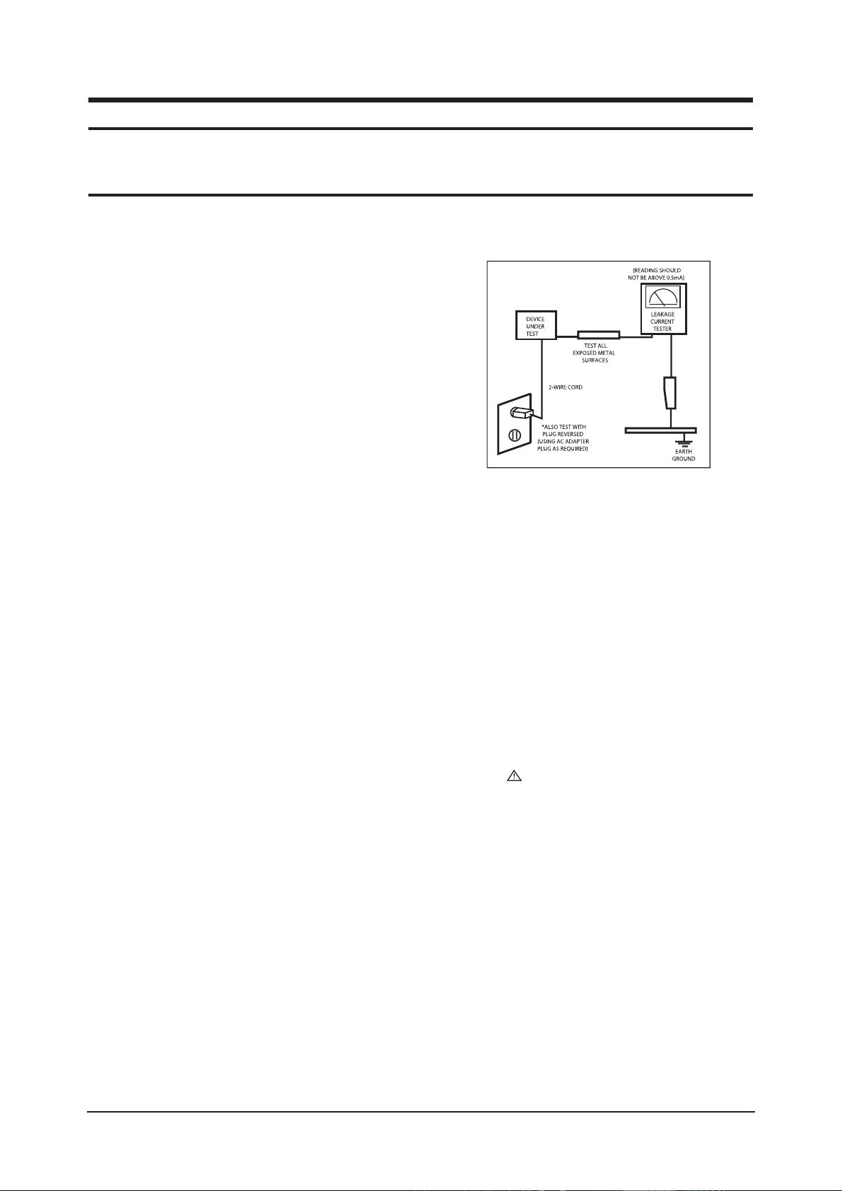
3. Leakage Current Hot Check (Figure 1-1):
WARNING : Do not use an isolation
transformer during this test.
Use a leakage current tester or a metering system that
complies with American National Standards Institute
(ANSI C101.1, Leakage Current for Appliances), and
Underwriters Laboratories (UL Publication UL1410,
59.7).
Figure 1-1. Leakage Current Test Circuit
4. With the unit completely reassembled, plug the AC line
cord directly into a 120V AC outlet. With the unit’s AC
switch first in the ON position and then OFF, measure
the current between a known earth ground (metal water
pipe, conduit, etc.) and all exposed metal parts,
including: metal cabinets, screwheads and control shafts.
The current measured should not exceed 0.5 milliamp.
Reverse the power-plug prongs in the AC outlet and
repeat the test.
1-1-4 Product Safety Notices
Some electrical and mechanical parts have special safetyrelated characteristics which are often not evident from visual
inspection. The protection they give may not be obtained by
replacing them with components rated for higher voltage,
wattage, etc. Parts that have special safety characteristics are
identified by on schematics and parts lists. A substitute
replacement that does not have the same safety characteristics
as the recommended replacement part might create shock, fire
and/or other hazards. Product safety is under review
continuously and new instructions are issued whenever
appropriate.
1 Precautions
Follow these safety, servicing and ESD precautions to prevent damage and to protect against potential hazards such as electrical shock.
1-1 Safety Precautions

1 Precautions
1-2
1-2-1 General Ser vicing
Precautions
1. Always unplug the unit’s AC power cord from the AC
power source and disconnect the DC Power Jack before
attempting to:
(a) remove or reinstall any component or assembly, (b)
disconnect PCB plugs or connectors, (c) connect a test
component in parallel with an electrolytic capacitor.
2. Some components are raised above the printed circuit
board for safety. An insulation tube or tape is sometimes
used. The internal wiring is sometimes clamped to
prevent contact with thermally hot components. Reinstall
all such elements to their original position.
3. After servicing, always check that the screws,
components and wiring have been correctly reinstalled.
Make sure that the area around the serviced part has not
been damaged.
1. Immediately before handling any semiconductor
components or assemblies, drain the electrostatic charge
from your body by touching a known earth ground.
Alternatively, wear a discharging wrist-strap device. To
avoid a shock hazard, be sure to remove the wrist strap
before applying power to the monitor.
2. After removing an ESD-equipped assembly, place it on a
conductive surface such as aluminum foil to prevent
accumulation of an electrostatic charge.
3. Do not use freon-propelled chemicals. These can
generate electrical charges sufficient to damage ESDs.
4. Use only a grounded-tip soldering iron to solder or
desolder ESDs.
5. Use only an anti-static solder removal device. Some
solder removal devices not classified as “anti-static” can
generate electrical charges sufficient to damage ESDs.
4. Check the insulation between the blades of the AC plug
and accessible conductive parts (examples: metal panels,
input terminals and earphone jacks).
5. Insulation Checking Procedure: Disconnect the power
cord from the AC source and turn the power switch ON.
Connect an insulation resistance meter (500 V) to the
blades of the AC plug.
The insulation resistance between each blade of the AC
plug and accessible conductive parts (see above) should
be greater than 1 megohm.
6. Always connect a test instrument’s ground lead to the
instrument chassis ground before connecting the positive
lead; always remove the instrument’s ground lead last.
6. Do not remove a replacement ESD from its protective
package until you are ready to install it. Most
replacement ESDs are packaged with leads that are
electrically shorted together by conductive foam,
aluminum foil or other conductive materials.
7. Immediately before removing the protective material
from the leads of a replacement ESD, touch the
protective material to the chassis or circuit assembly into
which the device will be installed.
Caution:Be sure no power is applied to the
chassis or circuit and observe all
other safety precautions.
8. Minimize body motions when handling unpackaged
replacement ESDs. Motions such as brushing clothes
together, or lifting your foot from a carpeted floor can
generate enough static electricity to damage an ESD.
1-3
Electrostatically Sensitive Devices (ESD) Precautions
Some semiconductor (solid state) devices can be easily damaged by static electricity. Such components are commonly called
Electrostatically Sensitive Devices (ESD). Examples of typical ESD are integrated circuits and some field-effect transistors. The
following techniques will reduce the incidence of component damage caused by static electricity.
1-2 Ser vicing Precautions
WARNING: An electrolytic capacitor installed with the wrong polarity might explode.
Caution: Before servicing units covered by this service manual, read and follow the Safety Precautions section
of this manual.
Note: If unforeseen circumstances create conflict between the following servicing precautions and any of the safety
precautions, always follow the safety precautions.

1 Precautions
1-3
1-4 Installation Precautions
1. For safety reasons, more than two people are
required for carrying the product.
2. Keep the power cord away from any heat emitting
devices, as a melted covering may cause fire or
electric shock.
3. Do not place the product in areas with poor
ventilation such as a bookshelf or closet. The
increased internal temperature may cause fire.
4. Bend the external antenna cable when connecting
it to the product. This is a measure to protect it
from being exposed to moisture. Otherwise, it
may cause a fire or electric shock.
5. Make sure to turn the power off and unplug the
power cord from the outlet before repositioning
the product. Also check the antenna cable or the
external connectors if they are fully unplugged.
Damage to the cord may cause fire or electric
shock.
6. Keep the antenna far away from any high-voltage
cables and install it firmly. Contact with the highvoltage
cable or the antenna falling over may
cause fire or electric shock.
7. When installing the product, leave enough space
(10cm) between the product and the wall for
ventilation purposes.
A rise in temperature within the product may cause fire.

1 Precautions
1-4
Memo

2 Product Specifications
2-1
2 Product Specifications
2-1 Fashion Feature
- RF, HDMI(DVI-D), PC(Analog), Component, Video, S-Video
- Brightness : 500cd/㎥
- Respense time : 16ms
- Dynamic contrast
- PIP (on PC only)
2 Product Specifications
2-2
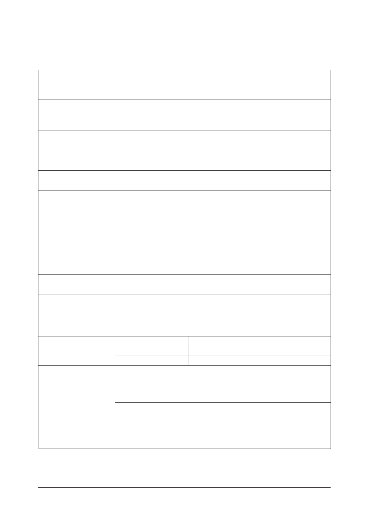
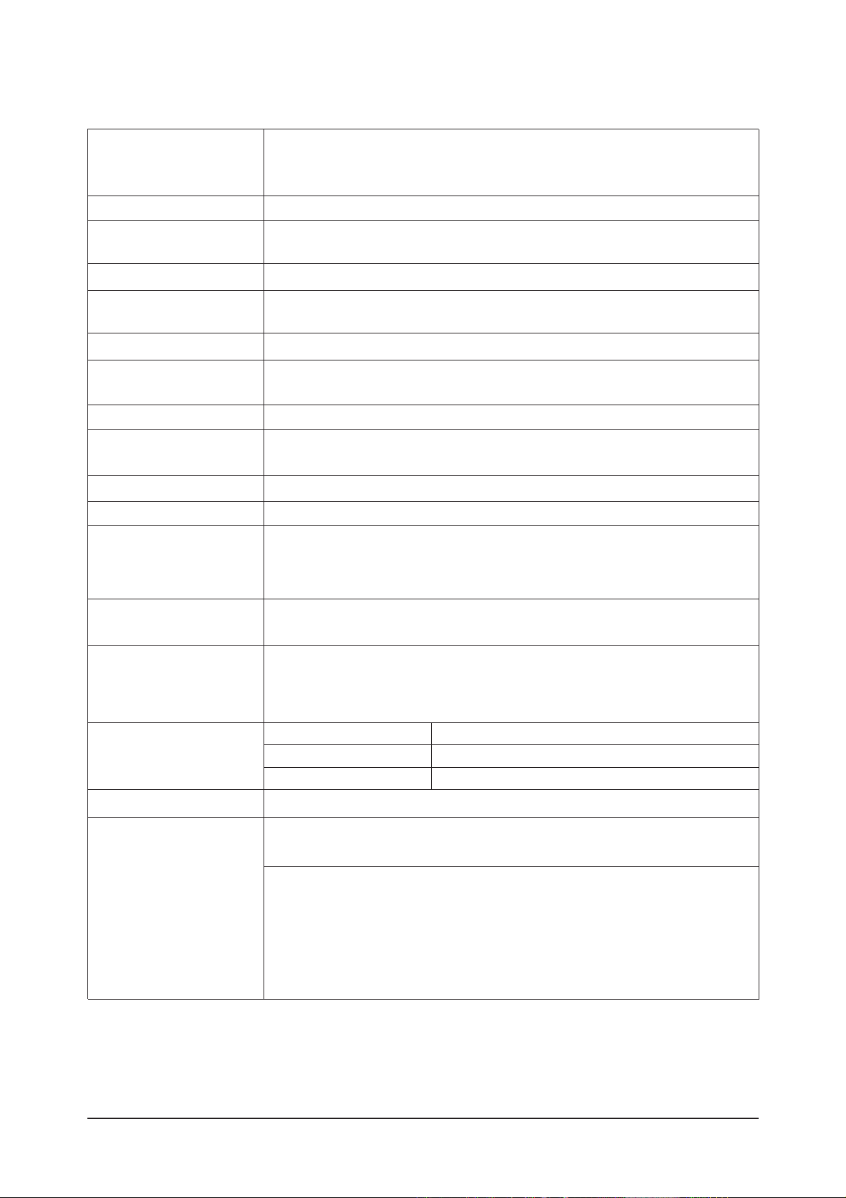
2-2 Specifications
2-2-1 LN-S4092D Specifications
LCD Panel
TFT-LCD panel, RGB vertical stripe, normaly white, 40-Inch viewable, 0.648 (H) x 0.648(V)mm pixel pitch
Scanning Frequency Horizontal : 30 kHz ~ 61 kHz (Automatic)
Vertical : 60 Hz ~ 75 Hz (Automatic)
Display Colors 16.7 Million colors
Maximum Resolution Horizontal : 1360 Pixels
Vertical : 768 Pixels
Input Video Signal Analog 0.7 Vp-p ±5% positive at 75Ω, internally terminated
Input Sync Signal Type : Seperate H/V
Level : TTL level
Maximum Pixel Clock rate
80 MHz
Active Display
Horizontal/Vertical
AC power voltage & Frequency
AC 110~120 ,60Hz
Power Consumption < 240 W ( < 1W, stand by )
Dimensions(W x D x H)
Set 1004 X 115 X 680 mm_without stand
1004 X 330 X 749 mm_ with stand
Weight
Set(With stand) 27.5 Kg
Environmental Considerations
Operating Temperature : 50˚F ~ 104˚F (10˚C ~ 40˚C)
Operating Humidity : 10 % ~ 80 %
Storage Temperature : -4˚F ~ 113˚F (-20˚C ~ 45˚C)
Storage Humidity : 5 % ~ 95 %
TV System
Antena Input
75Ω
- MAX Internal speaker Out : Right => 10W, Left => 10W
Sound Characteristic
- BASS Control Range : -8 dB ~ + 8dB
- TREBLE Control Range : -8 dB ~ +8 dB
- Headphone Out : 10 mW MAX
- Output Frequency : RF : 80 Hz ~ 15 kHz
A/V : 80 Hz ~ 20 kHz
System ATSC, NTSC
Item
Description
885.168 mm / 497.664 mm
Tunning Frequency Synthesize
Sound MONO, STEREO, SAP
2 Product Specifications
2-3
2-2-2 LN-S4692D Specifications
LCD Panel
TFT-LCD panel, RGB vertical stripe, normaly white, 46-Inch viewable, 0.7455 (H) x 0.2495(V)mm pixel pitch
Scanning Frequency Horizontal : 30 kHz ~ 61 kHz (Automatic)
Vertical : 60 Hz ~ 75 Hz (Automatic)
Display Colors 16.7 Million colors
Maximum Resolution Horizontal : 1360 Pixels
Vertical : 768 Pixels
Input Video Signal Analog 0.7 Vp-p ±5% positive at 75Ω, internally terminated
Input Sync Signal Type : Seperate H/V
Level : TTL level
Maximum Pixel Clock rate
80 MHz
Active Display
Horizontal/Vertical 1018.353 mm / 572.544 mm
AC power voltage & Frequency
AC 110V~120V, 60Hz
Power Consumption < 330W (< 1W, stand by )
Dimensions(W x D x H)
Set 1126 X 140 X 752 mm_without stand
800 X252 X 603 mm) With stand
Weight
Set(With stand) 37.0 kg
Environmental Considerations Operating Temperature : 50˚F ~ 104˚F (10˚C ~ 40˚C)
Operating Humidity : 10 % ~ 80 %
Storage Temperature : -4˚F ~ 113˚F (-20˚C ~ 45˚C)
Storage Humidity : 5 % ~ 95 %
TV System
Antena Input
75Ω
- MAX Internal speaker Out : Right => 10W, Left => 10W
Sound Characteristic
- BASS Control Range : -8 dB ~ + 8dB
- TREBLE Control Range : -8 dB ~ +8 dB
- Headphone Out : 10 mW MAX
- Output Frequency : RF : 80 Hz ~ 15 kHz
A/V : 80 Hz ~ 20 kHz
System ATSC, NTSC
Item
Description
Tunning Frequency Synthesize
Sound MONO, STEREO, SAP
2 Product Specifications
2-4
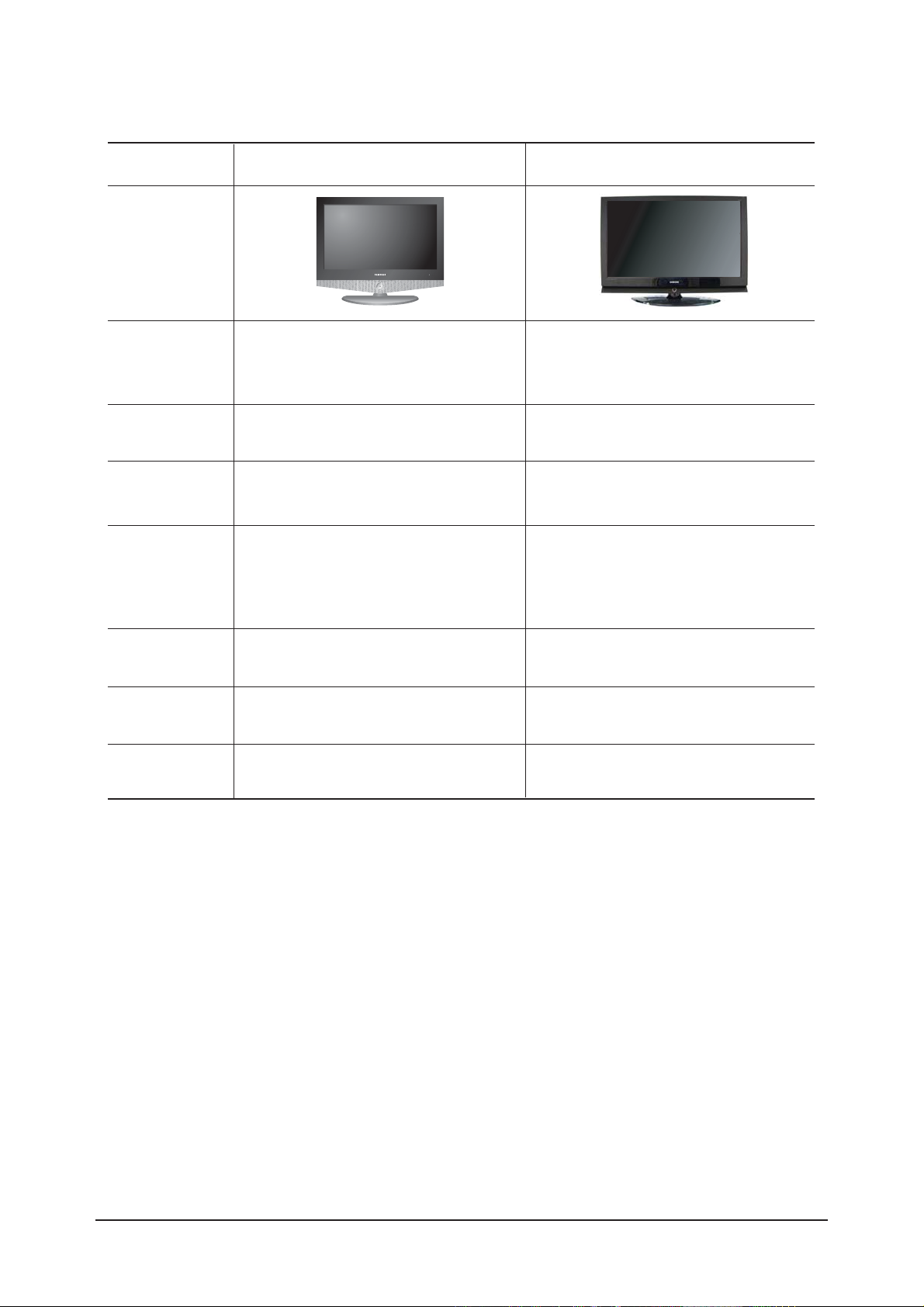
2-2-4 Spec Comparison
LN-R408D
Model
Design
F
Frequency
Horizontal
Vertical
Display Color
30 ~ 61 kHz
60 ~ 75 Hz
16,777,216 colors
30 ~ 61 kHz
60 ~ 75 Hz
16,777,216 colors
P
PC Resolution
Maximum mode
I
Input Signal
Sync Signal
Video Signal
PPower Consumption
Normal
Power Saving
100W / 140W / 170W
< 2W
240W / 330W
< 1W
H/V Separate, TTL, P. or N.
0.7 Vp-p @ 75ohm
H/V Separate, TTL, P. or N.
0.7 Vp-p @ 75ohm
1360 x 768 / 60 Hz 1360 x 768 / 80 Hz
I
Input source
Difference
DVI-D HDMI
PPIP
PIP(PC Only) PIP, POP
SSound
3W / 5W / 7.5W 10W
LN-S4092D / LN-S4692D

2 Product Specifications
2-5
Item Item Name
Remote Control &
Batteries (AAA x 2)
Power Cord
Cover-Bottom
Stand
Stand Screw (4 ea)
Owner's Instructions
Cleaning Cloth
Warranty Card /
Registration
Card /Safety Guide Manual
(Not available in all locations)
BN59-00511A
3903-000144
BN63-01938A
BN90-00821B
6002-001294
BN68-01001B
BN63-07198A
BN68-00860A
Code.No Remark
2-3 Option Specification

Memo
2 Product Specifications
2-6

3 Alignments and Adjustments
3-1
3 Alignments and Adjustments
3-1 General Alignment Instuction
1. Usually, a color LCD-TV needs only slight touch-up adjustment upon installation.
Check the basic characteristics such as height, horizontal and vertical sync.
2. Use the specified test equipment or its equivalent.
3. Correct impedance matching is essential.
4. Avoid overload. Excessive signal from a sweep generator might overload the front-end
of the TV. When inserting signal markers, do not allow the marker generator to distort test result.
5. Connect the TV only to an AC power source with voltage and frequency as specified on
the backcover nameplate.
6. Do not attempt to connect or disconnect any wire while the TV is turned on. Make sure
that the power cord is disconnected before replacing any parts.
7. To protect aganist shock hazard, use an isolation transform.
3 Alignments and Adjustments
3-2
3-2 Factory Mode Adjustments
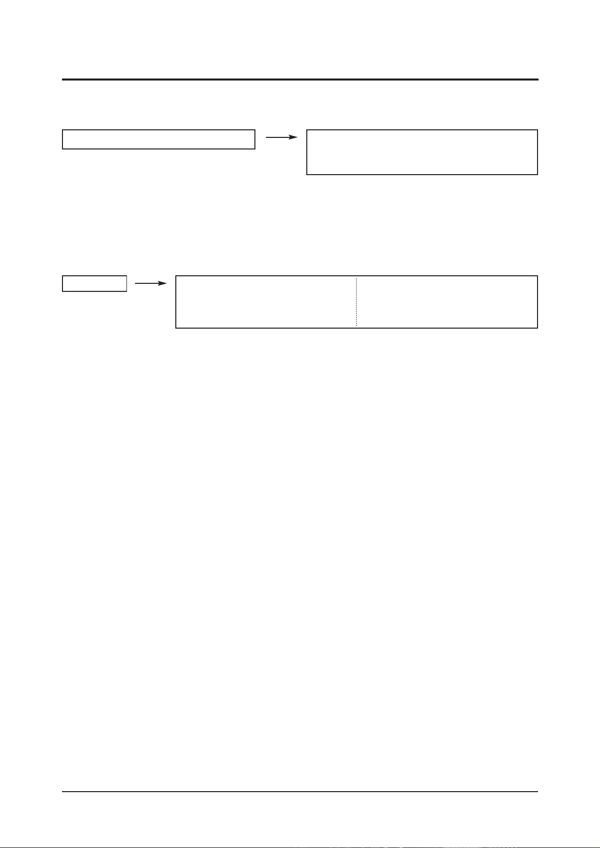
3-2-1 Entering Factory Mode
To enter 'Service Mode' Press the remote -control keys in this sequence :
- If you do not have Factory remote - control
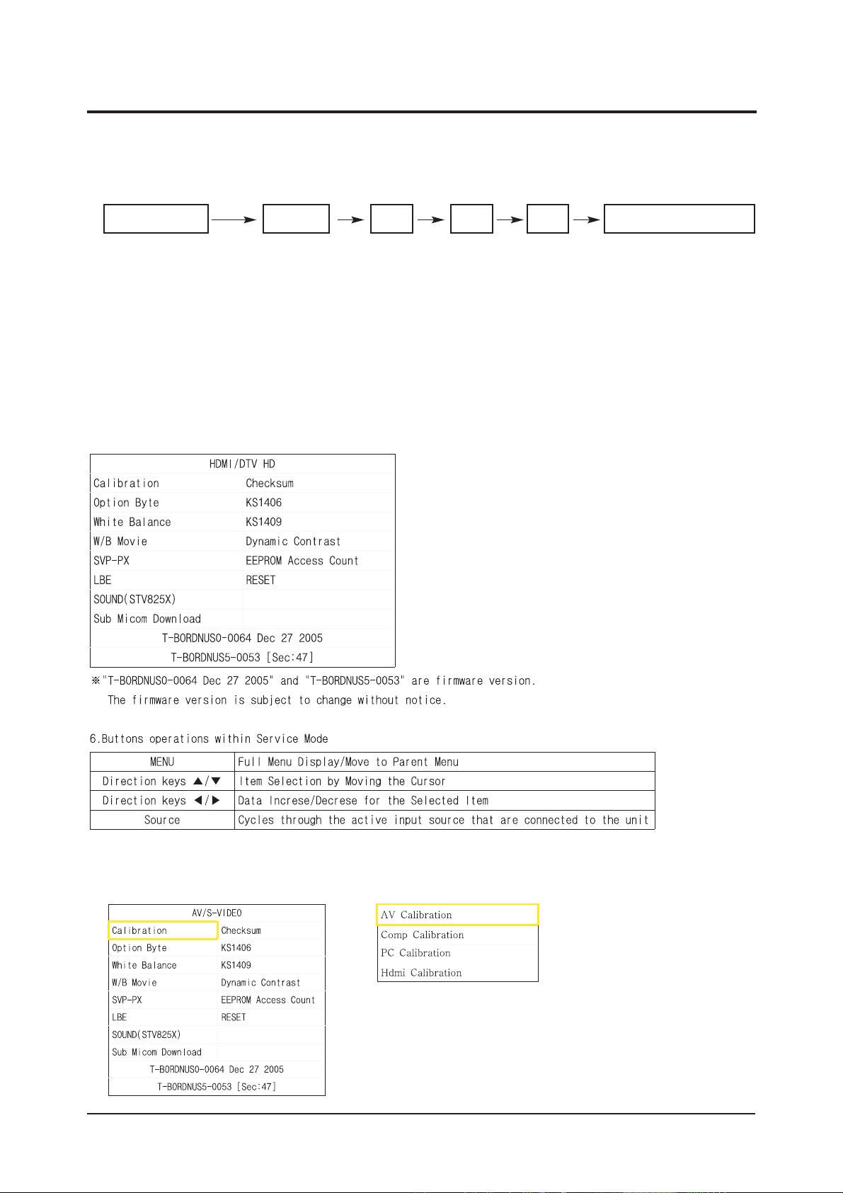
3-2-2 How to Access Service Mode
¡áUsing the Customer Remote
1.Turn the power off and set to stand-by mode
2.Press the remote buttons in this order; POWER OFF-MUTE-1-8-2-POWER ON to turn the set on.
3.The set turns on and enters service mode.
4.Press the Power button to exit and store data in memory.
¡ØIf you fail to enter service mode, repeat steps 1 and 2 above.
5.Initial SERVICE MODE DISPLAY State
Power OFF 1 8 2 Power OnMUTE
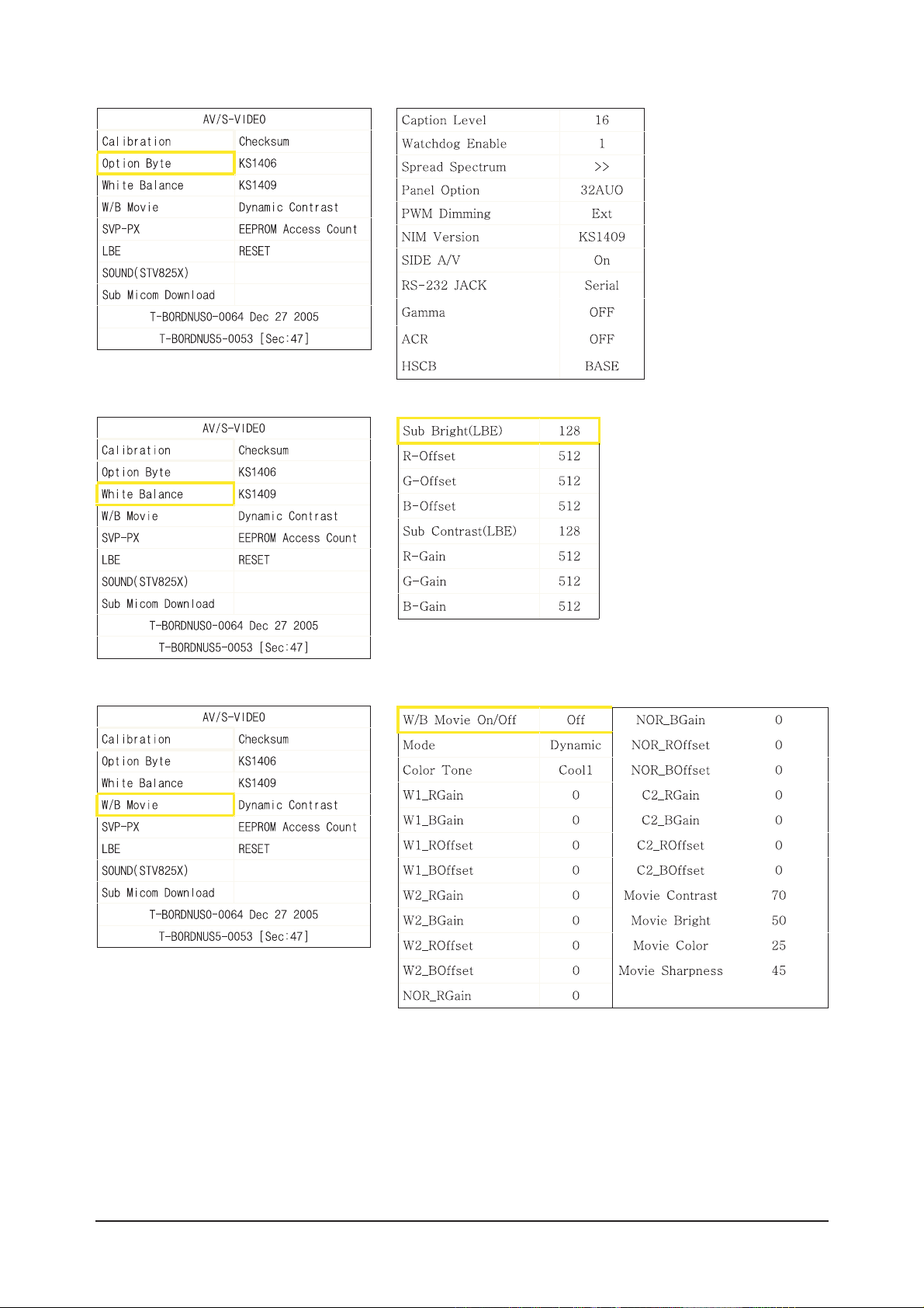
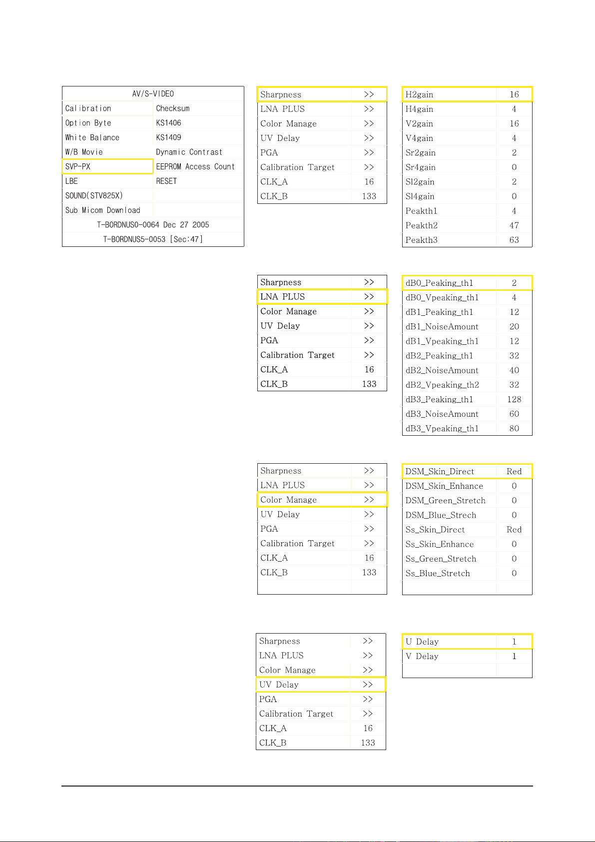
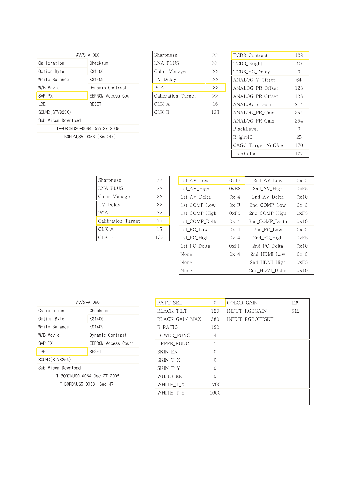
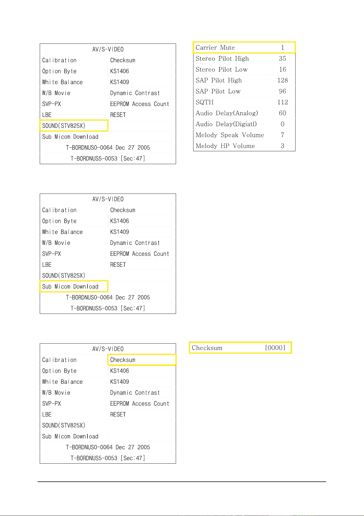
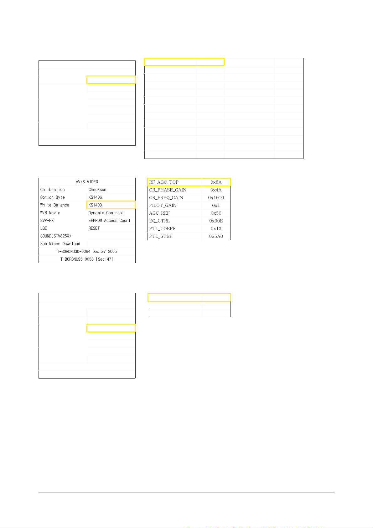
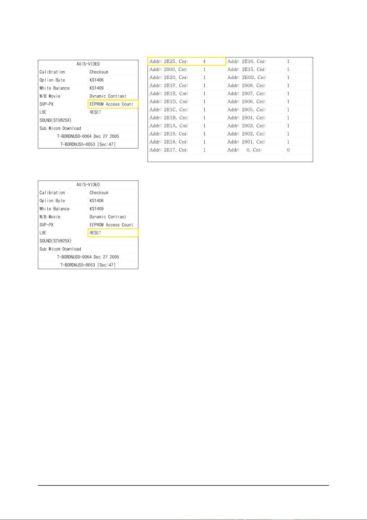
3-2-3 Factory Data
3 Alignments and Adjustments
3-3
3 Alignments and Adjustments
3-4
3 Alignments and Adjustments
3-5
3 Alignments and Adjustments
3-6
3 Alignments and Adjustments
3-7
AV/S-VIDEO
Calibration Checksum
Option Byte KS1406
White Balance KS1409
W/B Movie Dynamic Contrast
SVP-PX EEPROM Access Count
LBE RESET
SOUND(STV825X)
Sub Micom Download
T-BORDNUS0-0064 Dec 27 2005
T-BORDNUS5-0053 [Sec:47
]
AG C_REF[AIR] 0x50 PACKET _ERR_T H R 0x8
C R _F _G A I N[AIR] 0xD0B
C R _L _G A I N[AIR] 0x24
EQ_STEP[AIR] 0xB
PILO T _GA IN[AIR] 0x1612
AGC_REF[CABLE] 0x50
C R _F _G A I N[CABLE] 0xD0B
C R _L _G A IN [CA B L E] 0x24
EQ_STEP[CA BLE] 0xB
PILO T _GA IN[CABLE] 0x1
CR_F2_GAIN[CABLE] 0x1612
AV/S-VIDEO
Calibration Checksum
Option Byte KS1406
White Balance KS1409
W/B Movie Dynamic Contrast
SVP-PX EEPROM Access Count
LBE RESET
SOUND(STV825X)
Sub Micom Download
T-BORDNUS0-0064 Dec 27 2005
T-BORDNUS5-0053 [Sec:47
]
Dynam icCE On
Dynam icDimming O n
LBE Y_M EAN READ
3 Alignments and Adjustments
3-8
3 Alignments and Adjustments
3-9
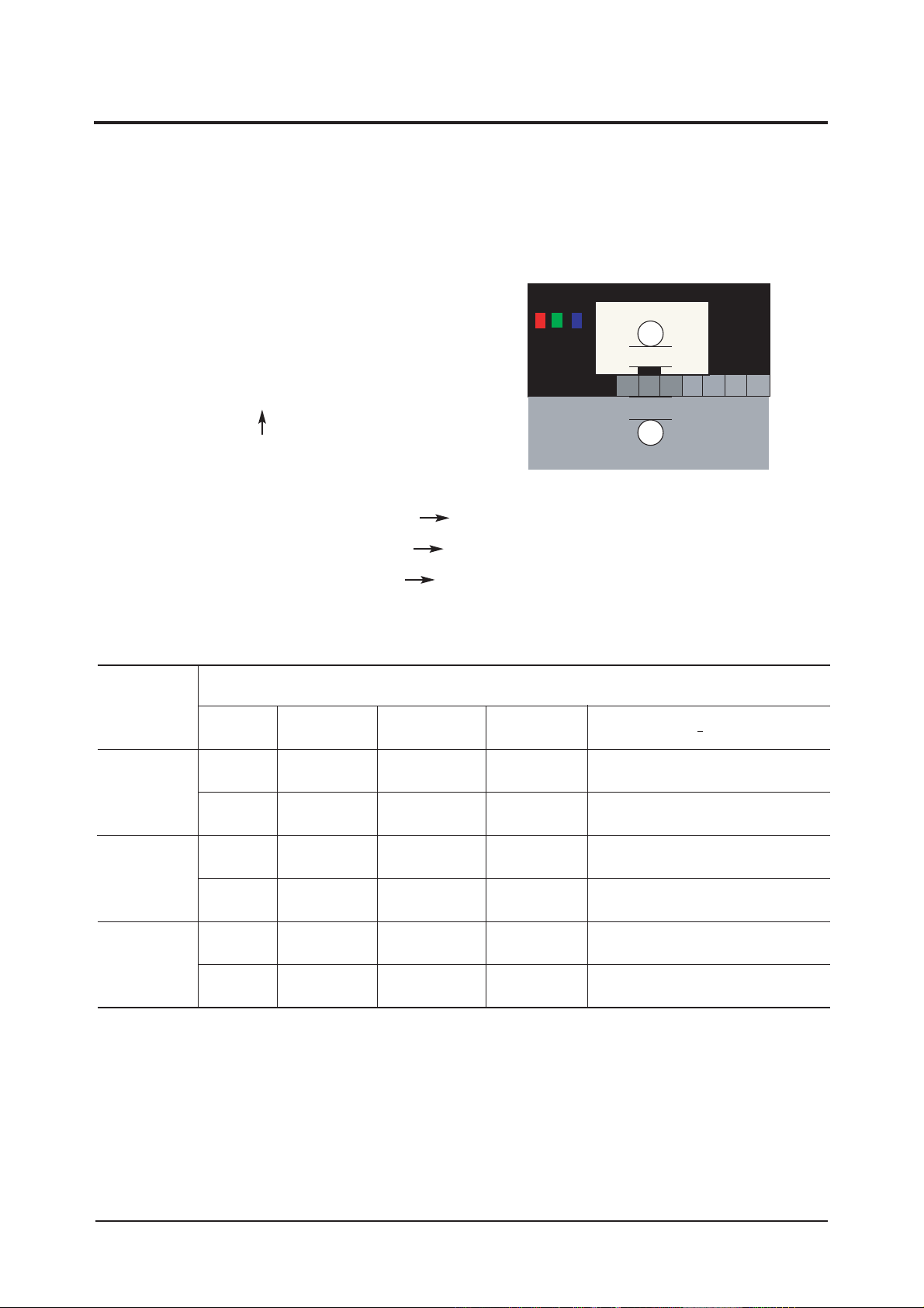
3-3 White Balance - Calibr ation
3-3-2 White Balance - Adjustment
3-3-1 White Balance -Calibration
3-3-3 Conditions for Measurement
1. Calibration
DTV Calibration
PC Calibration
(Calibration Condition refer to next page)
3. W/B
(low light) (hight light)
1. On the basis of toshiba ABL pattern : High Light level (57 IRE)
- INPUT SIGNAL GENERATOR : MSPG-925LTH
* Mode NO 1 : 744X484@60 Hz
NO 6 : 1280X720@60 Hz (Component 720P)
NO 21 : 1024X768@60 Hz
*
Pattern
NO 15 : Color bar
NO 16 : Toshiba ABL Pattern
NO 17 : 16 gray
2. Optical measuring device : CA210 (FL)
Please use the MSPG-925 LTH generator for model LN-S4092D, LN-S4692D.
(W/B adjustment Condition refer next page)
Sub Bright Sub Contrast
R offset R gain
G offset G gain
B offset B gain
3 Alignments and Adjustments
3-10
3-4 White Ratio (Balance) Adjustment
1. You can adjust the white ratio in factory mode (1:Calibration, 3:White-Balance).
2. Since the adjustment value and the data value vary depending on the input source, you have to
adjust these in CVBS, Component 1 and HDMI 1 modes.
3. The optimal values for each mode are configured by default. (Refer to Table 1, 2.)
It varies with Panel's size and Specification.
- Equipment : CS-1000
- Pattern: Master MSPG925 #16 "ABL Pattern" as standard
- Use other equipment only after comparing the result
with that of the Master equipment.
- Set Aging time : 30min
- Calibration and Manual setting for WB adjustment.
HDMI: No Calibration Manual adjustment at #16 pattern (720p)
COMP: Calibration at #24 Chessboard Pattern Manual adjustment at #16 pattern (720p)
CVBS: Calibration at #24 Chessboard Pattern Manual adjustment at #16 pattern (NTSC)
PC : Calibration at #24 Chessboard Pattern No Manual adjustment (1024x768@60Hz)
CVBS
L/L
L/L
H/L
L/L
H/L
L/L
T(K) + MPCD
Y (cd/m
2
)
-
-
3.8(1.1Ft)
4.2(1.2Ft)
-
4.2(1.2Ft)
y
263
263
263
263
263
263
Adjustment Coordinate
x
263
263
263
263
263
263
15000K/0
15000K/0
15000K/0
15000K/0
15000K/0
15000K/0
Component
(720p)
HDMI
(1080i)
-White Balance Manual Adjustment (ABL Pattern)
-Adjustment Specification
White Balance : High light (± 2), Low light (± 3)
Luminance : High light (Don't care), Low light (± 0.2 Ft/L)
20mm
20mm

3 Alignments and Adjustments
3-11
3-5 Ser vicing Infor mation
3-5-1 USB Download Method
1. Downloading boot code
©ç Change the boot code's file name into "boot.bin".
©è Copy the "boot.bin" into the path "/bordeaux/us" in USB flash driver.
©é Turn off LCD TV.
©ê Insert the USB flash driver into the service 1 jack of LCD TV.
©ë Turn on LCD TV.
©ì The banner osd "Updating SW..." is displayed.
©í The banner osd "Completed..." is displayed when the updating is completed.
©î Turn off and remove the USB flash driver from LCD TV
©ï Check the program version.
2. Downloading application code
©ç Change the application code's file name into "appl.rom".
©è Copy the "appl.rom" into the path "/bordeaux/us" in USB flash driver.
©é Turn off LCD TV.
©ê Insert the USB flash driver into the service 1 jack of LCD TV.
©ë Turn on LCD TV.
©ì The banner osd "Updating SW..." is displayed.
©í The banner osd "Completed..." is displayed when the updating is completed.
©î Turn off and remove the USB flash driver from LCD TV
©ï Check the program version.

3 Alignments and Adjustments
3-12
Memo

4 Troubleshooting
4-1
4 Troubleshooting
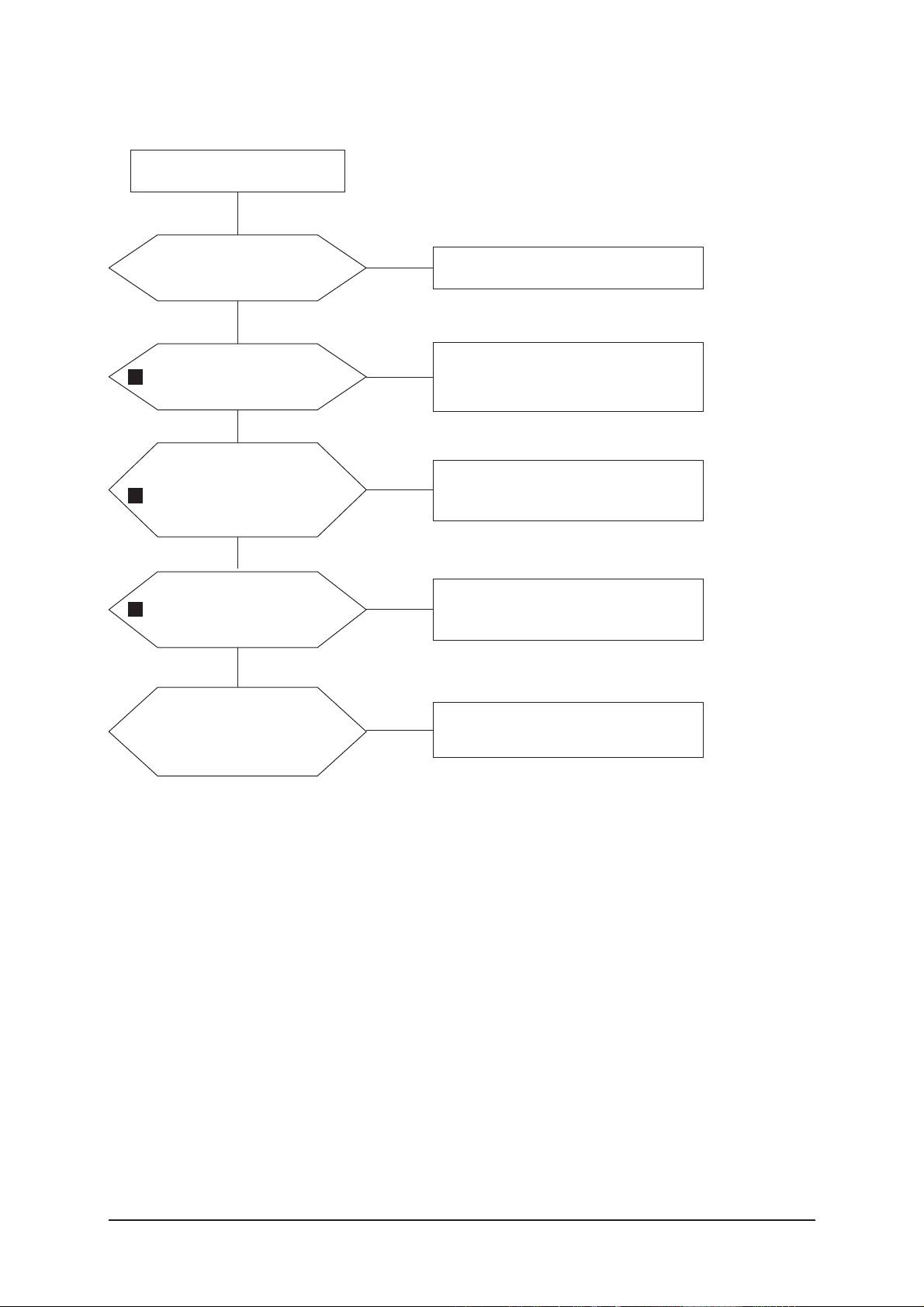
4-1 No Power
Does proper Stand-By DC A6.2V
appear at C156 ?
Change the Main Power Ass'y
26": BN96-03060A
32": BN96-03057A
40": BN44-00134A
Yes
Yes
Yes
No
Check a connection power cable.
P/N: BN39-00691B
No
Does proper Main DC
B12V,B5V,B12VS appear at
C106, C115, C119?
Yes
No
No
Does proper Inverter DC
24V appear at CNM802,
CNM803 in SMPS?
Check IC106, IC107
Change the Main Ass'y
BN94-00850A
Yes
Does proper DC A5V,A3.3V
appear at C154, C151 ?
Check
IC101, IC102, IC103, IC104, IC105
Change the Main Ass'y BN94-00850A
Yes
Yes
Yes
Yes
Does proper DC
B9V,B8V,VCC5P,B3.3V_1,B3.3V_2,
B5V_VCC appear at C108, C110,
C123, C128, C135, C133 ?
Does proper DC 1.8V appear at
C1103, C1154, C364, C1011 ?
Does proper DC 2.5V appear at
C1214, C1746 ?
A power is supplied to set ?
Check a other function (No picture part)
Replace a LCD Panel
26": BN07-00254A
32": BN07-00253A
40": BN07-00264A
No
No
Check IC1101, IC1102, IC304, IC1001
Change the Main Ass'y BN94-00850A
No
No
Check IC1201, IC1702
Change the Main Ass'y BN94-00850A
No
LAMP Off, power indicator LED
red color ?
4 Troubleshooting
4-2
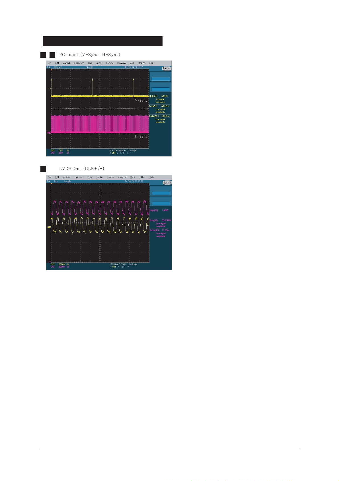
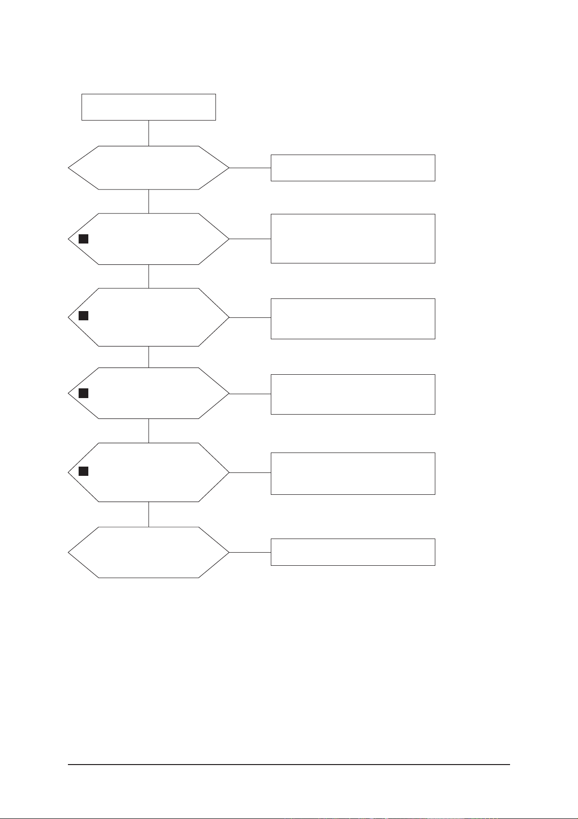
4-2 No Video (Analog PC Signal)
Check a PC source and
check the connection of
DSUB?
Input a analog PC signal.
Check a connected cable.
Yes
Does the signal appear at
#30,#22,#38,#41,#42
(R,G,B,H,V) of IC901?
Check JA801, PC cable.
Change a PC cable. Change a main
PCB ass'y
Yes
Does the digital data appear at
output of R1034~7, R1039?
Check IC901
Change a main PCB ass'y
Yes
Does the digital data
appear at output of
R1010~5, R1024~7?
Check IC1002
Change a main PCB ass'y
Yes
Check a LVDS cable?
Replace a LCD panel?
Please, Call to Samsung Co. LTD
Yes
Power Indicator is off.
Lamp on, no video
No
No
No
No
No
1
2
3
4 Troubleshooting
4-3
WAVEFORMS
1 2
3
4 Troubleshooting
4-4
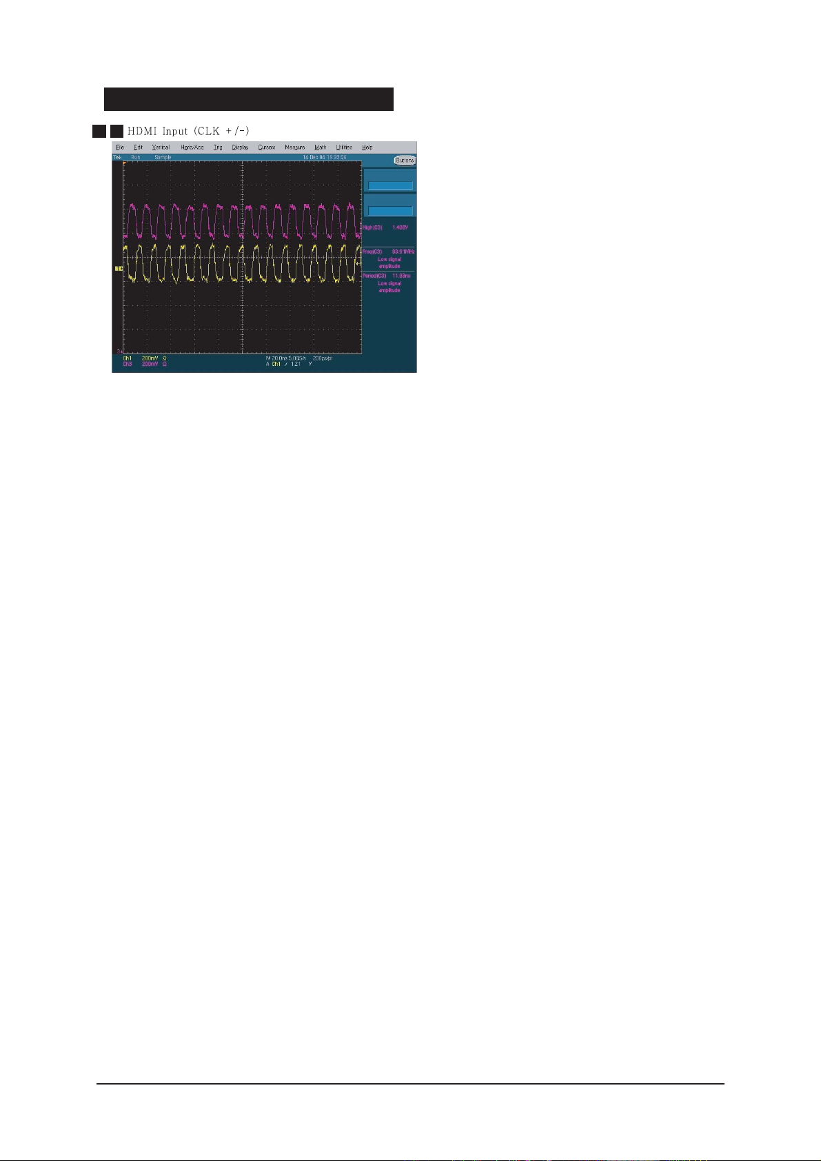
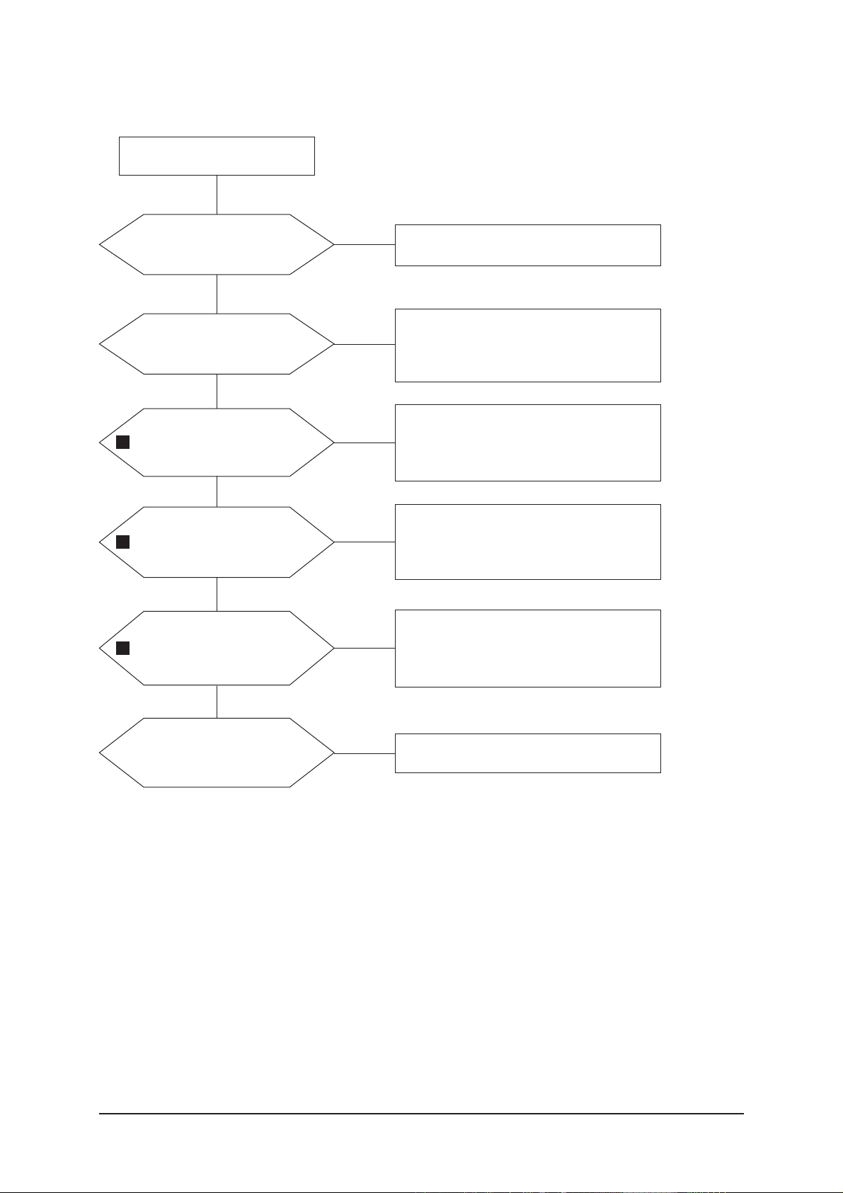
4-3 No Video (HDMI - Digital Signal)
Check a HDMI source and
check the connection of
HDMI cable?
Input a HDMI signal.
Check a connected cable.
Yes
Does the signal appear at
R874,R876,R878,R879,R88
2,R883,R886-R891(Data),
R884-5,R892-3(Clk+/-) ?
Check JA802, JA804, HDMI cable.
Change a HDMI cable. Change a
main PCB ass'y
Yes
Does the digital data
appear at output of
R901-8 ?
Check IC805
Change a main PCB ass'y
Yes
Does the digital data
appear at output of R1034-
7, R1039 ?
Check IC901
Change a main PCB ass'y
Yes
Does the digital data
appear at output of R1010-
5, R1024-7 ?
Check IC1002
Change a main PCB ass'y
Yes
Check a LVDS cable ?
Replace a LCD panel ?
Yes
Power Indicator is off.
Lamp on, no video.
No
No
No
No
No
Please, Call to Samsung Co. LTD.
No
4
5
6
7
4 Troubleshooting
4-5
WAVEFORMS
4 5
4 Troubleshooting
4-6
4-4 No Picture (Tuner_CVBS)
Check a RF source and
check the connection of RF
cable ?
Input a RF signal.
Check a connected cable.
Yes
Does the signal appear at
the main splitter cable ?
Check CN501.
Check splitter cable connection.
Change a main PCB ass'y or splitter
cable.
Yes
Does the signal appear at
C912 ?
Check TU501.
Change a main PCB ass'y or tuner.
Yes
Does the digital data
appear at output of
R1034-7, R1039 ?
Check IC901
Change a main PCB ass'y
Yes
Does the digital data
appear at output of R1010-
5, R1024-7 ?
Check IC1002
Change a main PCB ass'y
Yes
Check a LVDS cable ?
Replace a LCD panel ?
Yes
Power Indicator is off.
Lamp on, no picture.
No
No
No
No
No
Please, Call to Samsung Co. LTD.
No
8
9
10
 Loading...