

samsung LN23R71BAX, LN23R71WAX, LN26R71BAX, LN32R71BAX, LN40R71BAX Service Manual

TFT-LCD TV
Chassis GNB23MLA
GNB26MLA
GNB32MLA
GNB40MLA
Model LN23R71BAX
LN23R71WAX
LN26R71BAX
LN32R71BAX
LN40R71BAX
Manual
SERVICE
TFT-LCD TV Feature
- RF, HDMI, PC(Analog), Component, Video,
S-Video
- Brightness : 500cd/m2
- Contrast Ratio:
23"/ 26" : 3000:1, 32"/ 40" : 5000:1
- Response time : 8ms
- Dynamic contrast
- PIP(on COM, PC, HDMI)

Contents
11. Precautions
………………………………………………………………………………………………………………………………………
11-1
1-1 Safety Precautions ……………………………………………………………………………………………………………………… 1-1
1-2 Servicing Precautions …………………………………………………………………………………………………………………… 1-2
1-3 Static Electricity Precautions …………………………………………………………………………………………………………… 1-2
1-4 Installation Precautions…………………………………………………………………………………………………………………… 1-3
2
2. Product specifications
…………………………………………………………………………………………………………………………
22-1
2-1 Fashion Feature…………………………………………………………………………………………………………………………… 2-1
2-2 LN23R71BAX/LN23R71WAX Specifications ………………………………………………………………………………………… 2-2
2-3 LN26R71BAX Specifications …………………………………………………………………………………………………………… 2-3
2-4 LN32R71BAX Specifications …………………………………………………………………………………………………………… 2-4
2-5 LN40R71BAX Specifications …………………………………………………………………………………………………………… 2-5
2-6 Spec Comparison ………………………………………………………………………………………………………………………… 2-6
2-7 Option Specification ……………………………………………………………………………………………………………………… 2-7
3
3. Alignments and Adjustments
…………………………………………………………………………………………………………………
33-1
3-1 Service Instruction ……………………………………………………………………………………………………………………… 3-1
3-2 How to Access Service Mode …………………………………………………………………………………………………………… 3-2
3-3 Factory Data ……………………………………………………………………………………………………………………………… 3-3
3-4 Service Adjustment ……………………………………………………………………………………………………………………… 3-9
3-5 Software Upgrade ……………………………………………………………………………………………………………………… 3-12
4
4. Troubleshooting
………………………………………………………………………………………………………………………………
44-1
4-1 First Checklist for Troubleshooting ………………………………………………………………………………………………………4-1
4-2 Checkpoints by Error Mode ……………………………………………………………………………………………………………… 4-2
5
5. Exploded View and Parts List
…………………………………………………………………………………………………………………
55-1
5-1 LN23R71BAX/LN23R71WAX Exploded View ………………………………………………………………………………………… 5-1
5-2 LN23R71BAX Parts list…………………………………………………………………………………………………………………… 5-2
5-3 LN23R71WAX Parts list ………………………………………………………………………………………………………………… 5-2
5-4 LN26R71BAX Exploded View …………………………………………………………………………………………………………… 5-3
5-5 LN26R71BAX Parts list…………………………………………………………………………………………………………………… 5-4
5-6 LN32R71BAX Exploded View …………………………………………………………………………………………………………… 5-5
5-7 LN32R71BAX Parts list…………………………………………………………………………………………………………………… 5-6
5-8 LN40R71BAX Exploded View …………………………………………………………………………………………………………… 5-7
5-9 LN40R71BAX Parts list…………………………………………………………………………………………………………………… 5-8
6
6. Electrical Parts List
……………………………………………………………………………………………………………………………
66-1
6-1 LN23R71BAX/LN23R71WAX Parts List ……………………………………………………………………………………………… 6-1
6-2 LN26R71BAX Parts List ………………………………………………………………………………………………………………… 6-18
6-3 LN32R71BAX Parts List ………………………………………………………………………………………………………………… 6-33
6-4 LN40R71BAX Parts List ………………………………………………………………………………………………………………… 6-50

Contents
77. Block Diagram
…………………………………………………………………………………………………………………………………
77-1
8. WWiring Diagram
…………………………………………………………………………………………………………………………………
8
8-1
8-1 Wiring Diagram …………………………………………………………………………………………………………………………… 8-1
8-2 Main Board Layout ……………………………………………………………………………………………………………………… 8-2
8-3 PIN characteristic ………………………………………………………………………………………………………………………… 8-3
8-4 Power Board Layout ……………………………………………………………………………………………………………………… 8-6
9
9.
Schematic Diagrams
……………………………………………………………………………………………………………………………
9
9-1
9-1 Power_Sound Schematic Diagram ……………………………………………………………………………………………………… 9-1
9-2 Jack Schematic Diagram ………………………………………………………………………………………………………………… 9-2
9-3 Micom Schematic Diagram ……………………………………………………………………………………………………………… 9-3
9-4 SVP-PX/PX-Power/LBE-Option Schematic Diagram ………………………………………………………………………………… 9-4
9-5 Application Schematic Diagram ………………………………………………………………………………………………………… 9-5
1
10. Operating Instructions and Installation
………………………………………………………………………………………………………
110-1
10-1 Front …………………………………………………………………………………………………………………………………… 10-1
10-2 Connection Panel ……………………………………………………………………………………………………………………… 10-2
10-3 Remote control ………………………………………………………………………………………………………………………… 10-5
10-4 Installing the Stand …………………………………………………………………………………………………………………… 10-6
10-5 Installing the Wall Mount Kit ………………………………………………………………………………………………………… 10-6
1
11. Disassembly and Reassembly
………………………………………………………………………………………………………………
111-1
11-1 Disassembly …………………………………………………………………………………………………………………………… 11-1
11-2 Reassembly …………………………………………………………………………………………………………………………… 11-5
1
12. PCB Diagram
…………………………………………………………………………………………………………………………………
112-1
12-1 Main PCB Diagram …………………………………………………………………………………………………………………… 12-1
12-2 Power PCB Diagram 23" ………………………………………………………………………………………………………………12-2
12-3 Power PCB Diagram 26", 32" ………………………………………………………………………………………………………… 12-3
12-4 Power PCB Diagram 40" ……………………………………………………………………………………………………………… 12-4
1
13. Circuit Descriptions
……………………………………………………………………………………………………………………………
113-1
13-1 Block description ……………………………………………………………………………………………………………………… 13-1
13-2 Main Block ……………………………………………………………………………………………………………………………… 13-3
13-3 SMPS Board …………………………………………………………………………………………………………………………… 13-4
1
14. Reference Infomation
………………………………………………………………………………………………………………………
114-1
14-1 Technical Terms ……………………………………………………………………………………………………………………… 14-1
14-2 Pin Assignments ……………………………………………………………………………………………………………………… 14-4
14-3 Timing Chart …………………………………………………………………………………………………………………………… 14-6
14-4 Panel Description …………………………………………………………………………………………………………………… 14-10
1 Precautions
1-1
1-1-1 Warnings
1. For continued safety, do not attempt to modify the
circuit board.
2. Disconnect the AC power and DC Power Jack before
servicing.
1-1-2 Ser vicing the LCD Monitor
1. When servicing the LCD Monitor Disconnect the AC
line cord from the AC outlet.
2. It is essential that service technicians have an accurate
voltage meter available at all times. Check the
calibration of this meter periodically.
1-1-3 Fire and Shock Hazard
Before returning the monitor to the user, perform the
following safety checks:
1. Inspect each lead dress to make certain that the leads
are not pinched or that hardware is not lodged between
the chassis and other metal parts in the monitor.
2. Inspect all protective devices such as nonmetallic
control knobs, insulating materials, cabinet backs,
adjustment and compartment covers or shields,
isolation resistor-capacitor networks, mechanical
insulators, etc.
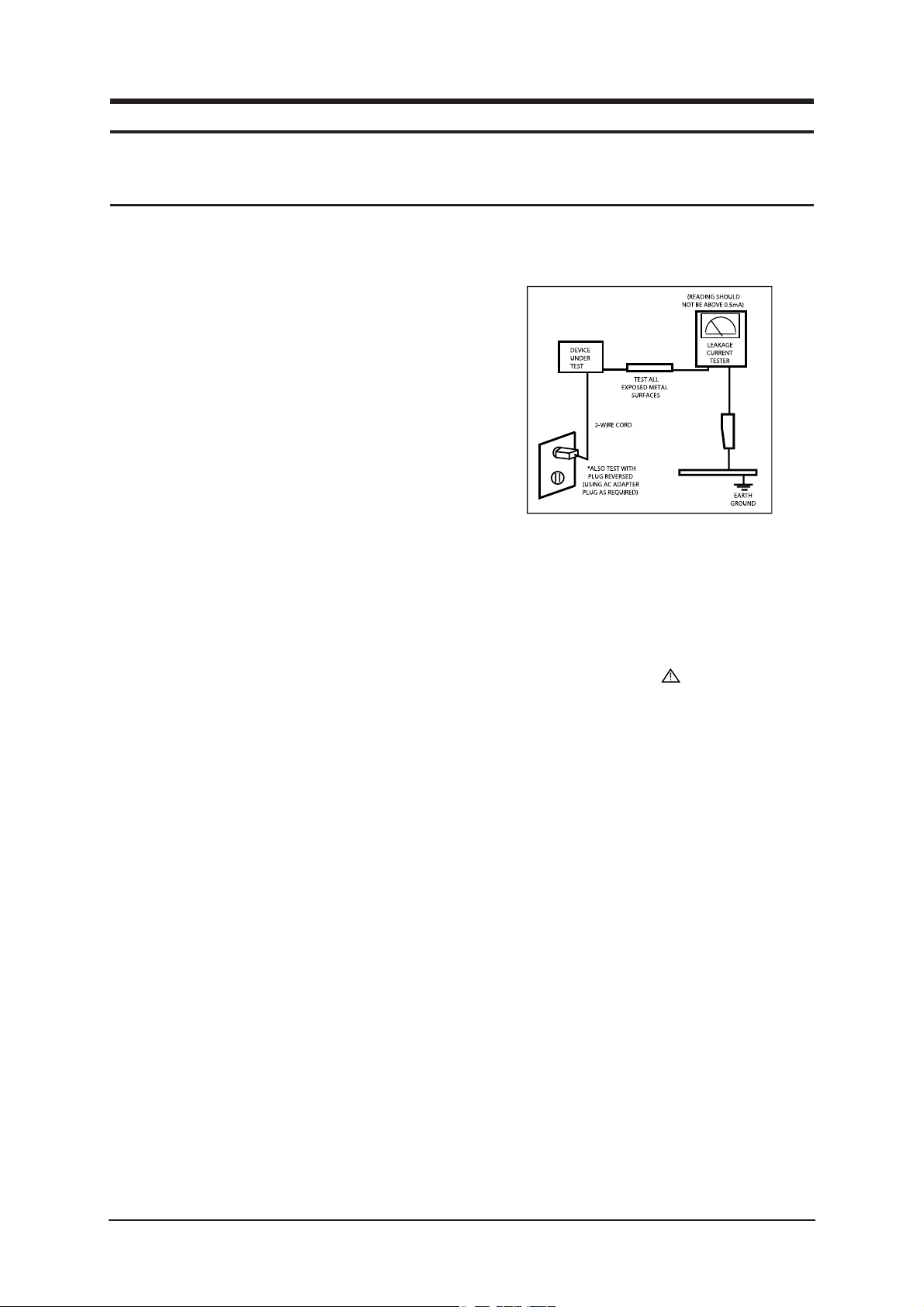
3. Leakage Current Hot Check (Figure 1-1):
WARNING: Do not use an isolation
transformer during
this test.
Use a leakage current tester or a metering system
that complies with American National Standards
Institute (ANSI C101.1, Leakage Current for
Appliances), and Underwriters Laboratories
(UL Publication UL1410, 59.7).
Figure 1-1. Leakage Current Test Circuit
1-1-4 Product Safety Notices
Some electrical and mechanical parts have special
safety-related characteristics which are often not evident
from visual inspection. The protection they give may not
be obtained by replacing them with components rated for
higher voltage, wattage, etc. Parts that have special safety
characteristics are identified by on schematics and parts
lists. A substitute replacement that does not have the same
safety characteristics as the recommended replacement part
might create shock, fire and/or other hazards. Product
safety is under review continuously and new instructions
are issued whenever appropriate.
1 Precautions
Follow these safety, servicing and ESD precautions to prevent damage and to protect against potential hazards such as electrical shock.
1-1 Safety Precautions

1 Precautions
1-2
1-2-1 General Ser vicing
Precautions
1. Always unplug the units AC power cord from the AC
power source and disconnect the DC Power Jack
before attempting to:
(a) remove or reinstall any component or assembly, (b)
disconnect PCB plugs or connectors, (c) connect a test
component in parallel with an electrolytic capacitor.
2. Some components are raised above the printed circuit
board for safety. An insulation tube or tape is
sometimes used. The internal wiring is sometimes
clamped to prevent contact with thermally hot
components. Reinstall all such elements to their
original position.
3. After servicing, always check that the screws,
components and wiring have been correctly
reinstalled. Make sure that the area around the
serviced part has not been damaged.
1. Immediately before handling any semiconductor
components or assemblies, drain the electrostatic
charge from your body by touching a known earth
ground. Alternatively, wear a discharging wrist-strap
device. To avoid a shock hazard, be sure to remove the
wrist strap before applying power to the monitor.
2. After removing an ESD-equipped assembly, place it
on a conductive surface such as aluminum foil to
prevent accumulation of an electrostatic charge.
3. Do not use freon-propelled chemicals. These can
generate electrical charges sufficient to damage ESDs.
4. Use only a grounded-tip soldering iron to solder or
desolder ESDs.
5. Use only an anti-static solder removal device. Some
solder removal devices not classified as anti-static
can generate electrical charges sufficient to damage
ESDs.
4. Check the insulation between the blades of the AC
plug and accessible conductive parts (examples: metal
panels, input terminals and earphone jacks).
5. Insulation Checking Procedure: Disconnect the power
cord from the AC source and turn the power switch
ON. Connect an insulation resistance meter (500 V) to
the blades of the AC plug.
The insulation resistance between each blade of the
AC plug and accessible conductive parts (see above)
should be greater than 1 megohm.
6. Always connect a test instruments ground lead to the
instrument chassis ground before connecting the
positive lead; always remove the instruments ground
lead last.
6. Do not remove a replacement ESD from its protective
package until you are ready to install it. Most
replacement ESDs are packaged with leads that are
electrically shorted together by conductive foam,
aluminum foil or other conductive materials.
7. Immediately before removing the protective material
from the leads of a replacement ESD, touch the
protective material to the chassis or circuit assembly
into which the device will be installed.
Caution: Be sure no power is applied to
the chassis or circuit and
observe all other safety
precautions.
8. Minimize body motions when handling unpackaged
replacement ESDs. Motions such as brushing clothes
together, or lifting your foot from a carpeted floor can
generate enough static electricity to damage an ESD.
1-3 Static Electricity Precautions
Some semiconductor (solid state) devices can be easily damaged by static electricity. Such components are commonly called
Electrostatically Sensitive Devices (ESD). Examples of typical ESD are integrated circuits and some field-effect transistors.
The following techniques will reduce the incidence of component damage caused by static electricity.
1-2 Ser vicing Precautions
WARNING: An electrolytic capacitor installed with the wrong polarity might explode.
Caution: Before servicing units covered by this service manual, read and follow the Safety
Precautions section of this manual.
Note: If unforeseen circumstances create conflict between the following servicing precautions and any of the safety
precautions, always follow the safety precautions.
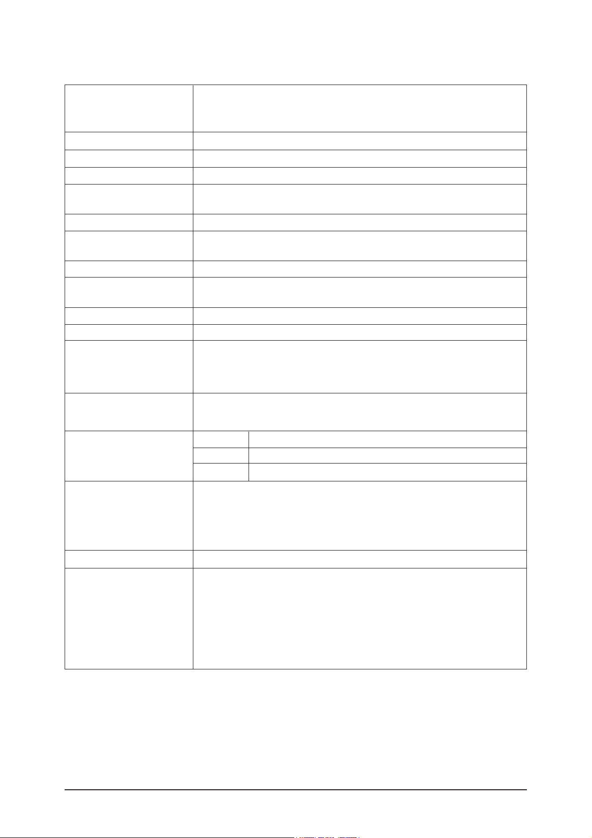
2-2 LN23R71BAX/LN23R71WAX Specifications
2 Product Specifications
2-2
Item
LCD Panel
Description
TFT-LCD panel, RGB vertical stripe, normaly white, 23-Inch viewable, 0.372 (H) x 0.372(V)mm pixel pitch
Scanning Frequency
Horizontal : 30 kHz ~ 61 kHz (Automatic) / Vertical : 60 Hz ~ 75 Hz (Automatic)
Display Colors
16.7 Million colors
Input Video Signal
Analog 0.7 Vp-p ±5% positive at 75Ω , internally terminated
Maximum Pixel Clock rate
80 MHz
AC power voltage & Frequencya
AC 110 , 60Hz
Power Consumption
100 W < 1 W
Antenna Input
75Ω
Environmental Considerations
Operating Temperature : 10°C ~ 40°C
Operating Humidity : 10 % ~ 80 %, non-condensing
Storage Temperature : -20°C ~ 45°C
Storage Humidity : 5 % ~ 95 %, non-condensing
Sound Characteristic
-MAX Internal speaker Out : Right : 5W / Left : 5W
-BASS Control Range : -8 dB ~ + 8dB
-TREBLE Control Range : -8 dB ~ +8 dB
-Headphone Out : 10 mW MAX
-Output Frequency : RF : 80 Hz ~ 15 kHz
A/V : 80 Hz ~ 20 kHz
TV System
Tuning
System
Sound
Frequency Synthesize
NTSC-M
MONO, STEREO, SAP
Dimensions(W x D x H)
Set
594 x 75 x 425.5 mm (23.38 x 2.95 x 16.75 inch)_with out stand
594 x 215.5 x 475.5 mm (23.38 x 8.48 x 18.72)_ with stand
Weight
Set(After installation Stand)
8 kg (17 Ibs)
Active Display
Horizontal/Vertical
508.125 mm / 285.696 mm
Input Sync Signal
Type : Seperate H/V
Level : TTL level
Maximum Resolution
Horizontal : 1360 Pixels
Vertical : 768 Pixels

2 Product Specifications
2-3
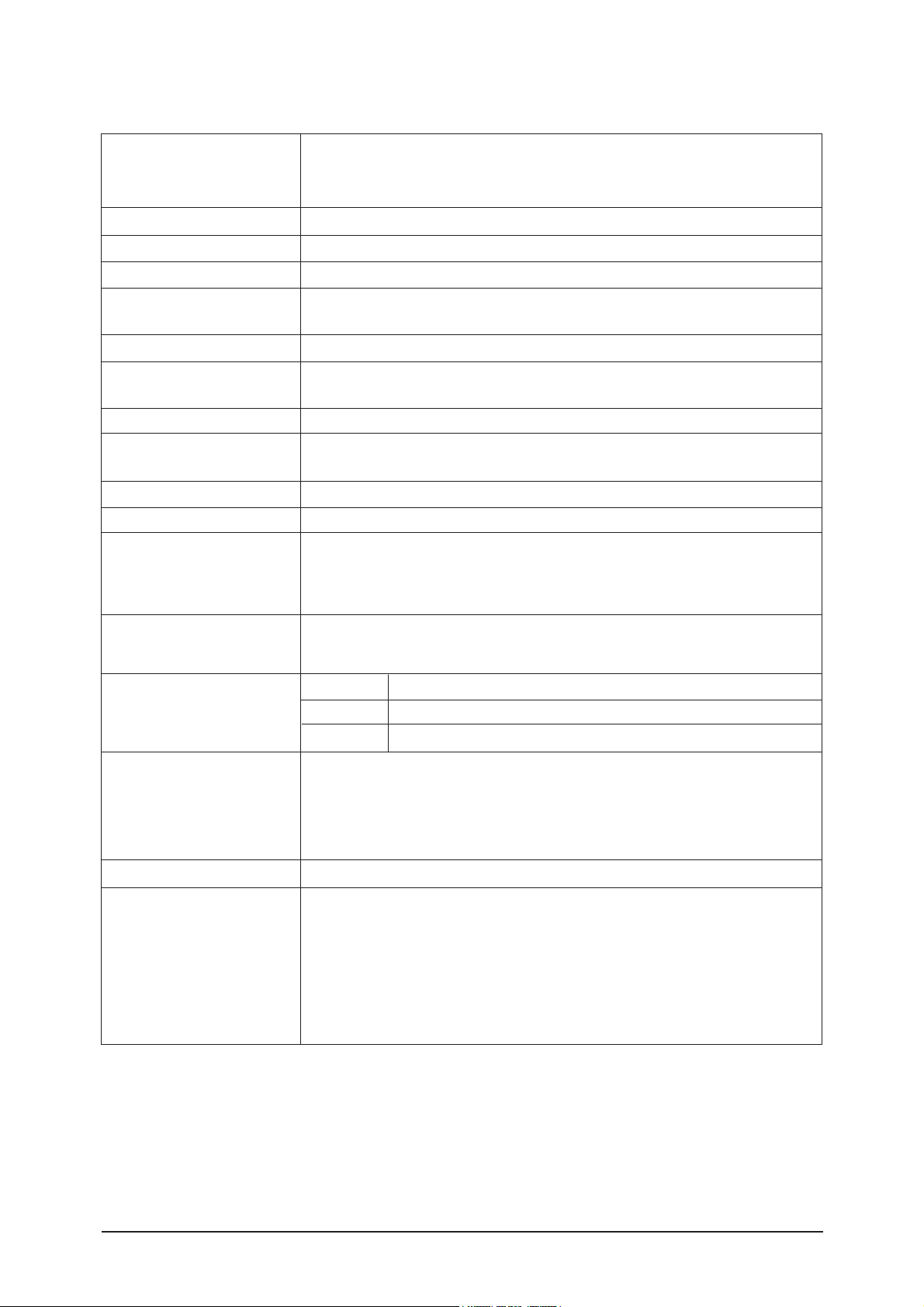
2-3 LN26R71BAX Specifications
2 Product Specifications
Item
LCD Panel
Description
TFT-LCD panel, RGB vertical stripe, normaly white, 26-Inch viewable, 0.372 (H) x 0.372(V)mm pixel pitch
Scanning Frequency
Horizontal : 30 kHz ~ 61 kHz (Automatic) / Vertical : 60 Hz ~ 75 Hz (Automatic)
Display Colors
16.7 Million colors
Input Video Signal
Analog 0.7 Vp-p ±5% positive at 75Ω , internally terminated
Maximum Pixel Clock rate
80 MHz
AC power voltage & Frequencya
AC 110 , 60Hz
Power Consumption
120 W < 1 W
Antenna Input
75Ω
Environmental Considerations
Operating Temperature : 10°C ~ 40°C
Operating Humidity : 10 % ~ 80 %, non-condensing
Storage Temperature : -20°C ~ 45°C
Storage Humidity : 5 % ~ 95 %, non-condensing
Sound Characteristic
-MAX Internal speaker Out : Right : 5W / Left : 5W
-BASS Control Range : -8 dB ~ + 8dB
-TREBLE Control Range : -8 dB ~ +8 dB
-Headphone Out : 10 mW MAX
-Output Frequency : RF : 80 Hz ~ 15 kHz
A/V : 80 Hz ~ 20 kHz
TV System
Tuning
System
Sound
Frequency Synthesize
NTSC-M
MONO, STEREO, SAP
Dimensions(W x D x H)
Set
675 x 75 x 475.5mm (26.57 x 2.95 x 18.72 inch)_with out stand
675 x 215.5 x 530 mm (26.57 x 8.48 x 20.86 inch)_ with stand
Weight
Set(After installation Stand)
10 kg (23 lbs)
Active Display
Horizontal/Vertical
575.77mm / 323.71mm
Input Sync Signal
Type : Seperate H/V
Level : TTL level
Maximum Resolution
Horizontal : 1360 Pixels
Vertical : 768 Pixels

2 Product Specifications
2-4
2-4 LN32R71BAX Specifications
Item
LCD Panel
Description
TFT-LCD panel, RGB vertical stripe, normaly white, 32-Inch viewable, 0.372 (H) x 0.372(V)mm pixel pitch
Scanning Frequency
Horizontal : 30 kHz ~ 61 kHz (Automatic) / Vertical : 60 Hz ~ 75 Hz (Automatic)
Display Colors
16.7 Million colors
Input Video Signal
Analog 0.7 Vp-p ±5% positive at 75Ω , internally terminated
Maximum Pixel Clock rate
80 MHz
AC power voltage & Frequencya
AC 110 , 60Hz
Power Consumption
150 W < 1 W
Antenna Input
75Ω
Environmental Considerations
Operating Temperature : 10°C ~ 40°C
Operating Humidity : 10 % ~ 80 %, non-condensing
Storage Temperature : -20°C ~ 45°C
Storage Humidity : 5 % ~ 95 %, non-condensing
Sound Characteristic
-MAX Internal speaker Out : Right : 10W / Left : 10W
-BASS Control Range : -8 dB ~ + 8dB
-TREBLE Control Range : -8 dB ~ +8 dB
-Headphone Out : 10 mW MAX
-Output Frequency : RF : 80 Hz ~ 15 kHz
A/V : 80 Hz ~ 20 kHz
TV System
Tuning
System
Sound
Frequency Synthesize
NTSC-M
MONO, STEREO, SAP
Dimensions(W x D x H)
Set
800 x 80 x 548.5 mm (31.49 x 3.14 x 21.59 inch)_with out stand
800 x 252 x 603 mm (31.49 x 9.92 x 23.74 inch)_With stand
Weight
Set(After installation Stand)
15 kg (33 lbs)
Active Display
Horizontal/Vertical
697.68mm / 392.26mm
Input Sync Signal
Type : Seperate H/V
Level : TTL level
Maximum Resolution
Horizontal : 1360 Pixels
Vertical : 768 Pixels
2 Product Specifications
2-5
2-5 LN40R71BAX Specifications
Item
LCD Panel
Description
TFT-LCD panel, RGB vertical stripe, normaly white, 40-Inch viewable, 0.511 (H) x 0.511(V)mm pixel pitch
Scanning Frequency
Horizontal : 30 kHz ~ 61 kHz (Automatic) / Vertical : 60 Hz ~ 75 Hz (Automatic)
Display Colors
16.7 Million colors
Input Video Signal
Analog 0.7 Vp-p ±5% positive at 75Ω , internally terminated
Maximum Pixel Clock rate
80 MHz
AC power voltage & Frequencya
AC 110 , 60Hz
Power Consumption
210 W < 1 W
Antenna Input
75Ω
Environmental Considerations
Operating Temperature : 10°C ~ 40°C
Operating Humidity : 10 % ~ 80 %, non-condensing
Storage Temperature : -20°C ~ 45°C
Storage Humidity : 5 % ~ 95 %, non-condensing
Sound Characteristic
-MAX Internal speaker Out : Right : 10W / Left : 10W
-BASS Control Range : -8 dB ~ + 8dB
-TREBLE Control Range : -8 dB ~ +8 dB
-Headphone Out : 10 mW MAX
-Output Frequency : RF : 80 Hz ~ 15 kHz
A/V : 80 Hz ~ 20 kHz
TV System
Tuning
System
Sound
Frequency Synthesize
NTSC-M
MONO, STEREO, SAP
Dimensions(W x D x H)
Set
991.5 x 87 x 658.5 mm (39.03 x 3.42 x 25.92 inch)_with out stand
991.5 x 326 x 713 mm (39.03 x 12.83 x 28.07 inch)_with stand
Weight
Set(After installation Stand)
23 kg (50 lbs)
Active Display
Horizontal/Vertical
885.17 mm / 497.64mm
Input Sync Signal
Type : Seperate H/V
Level : TTL level
Maximum Resolution
Horizontal : 1360 Pixels
Vertical : 768 Pixels
2 Product Specifications
2-6
LN26R71BX/LN32R71BX/LN40R71BXModel
Design
Frequency
Horizontal
Vertical
Display Color
30 ~ 61 kHz
60 ~ 75 Hz
16,777,216 colors
30 ~ 61 kHz
60 ~ 75 Hz
16,777,216 colors
PC Resolution
Maximum mode
Input Signal
Sync Signal
Video Signal
Power
Consumption
Normal
Power Saving
Input source
Difference
100W / 152W / 205W
< 1W
HDMI HDMI
PIP
PIP, POP
PIP, POP
Sound Output
3W / 5W / 10W 5W / 10W
100W / 120W / 150W / 210W
< 1W
H/V Separate, TTL, P. or N.
0.7 Vp-p @ 75ohm
H/V Separate, TTL, P. or N.
0.7 Vp-p @ 75ohm
WXGA, 1360 x 768 @ 60 Hz
1360 x 768 / 60 Hz
LN23R71BAX/LN23R71WAX/LN26R71BAX/
LN32R71BAX/LN40R71BAX
2-6 Spec Comparison
2 Product Specifications
2-7
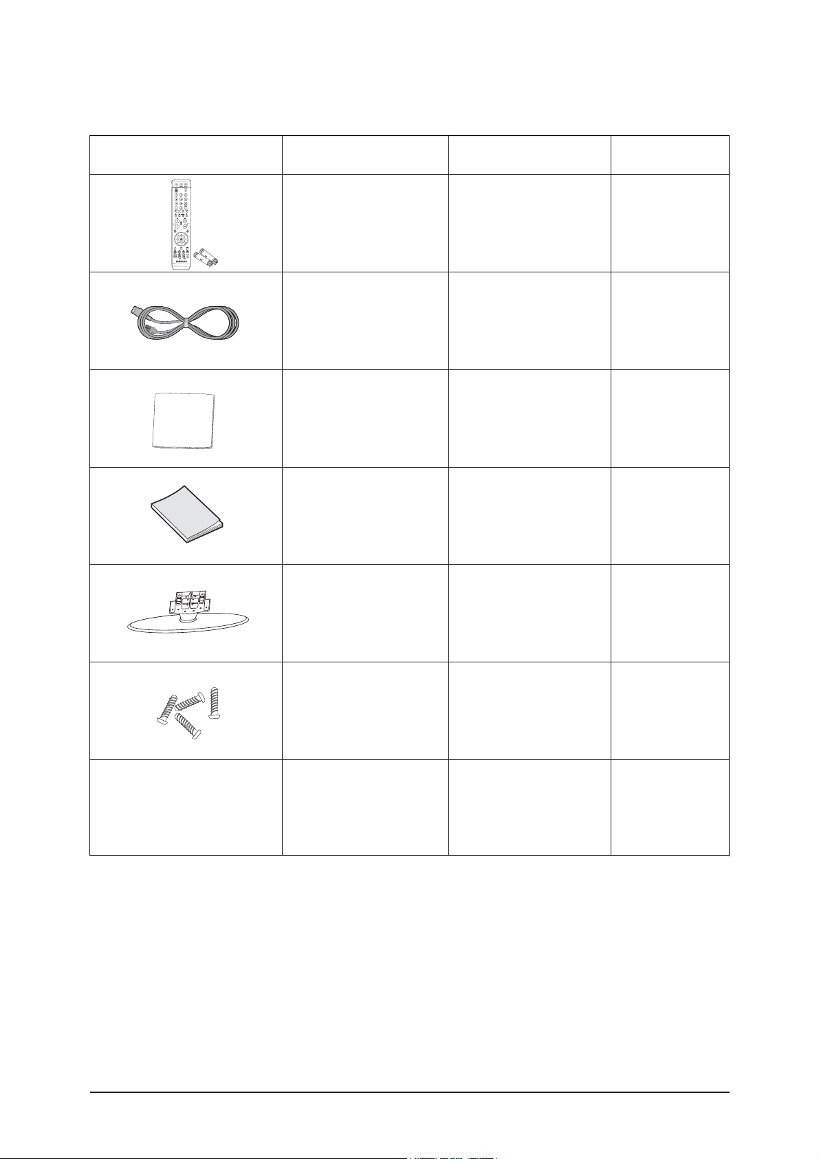
2-7 Option Specification
Item Item Name
Remote Control
&
Batteries (AAA x 2)
Power Cord
Cleaning Cloth
Owner's
Instructions
Stand
Stand Screw
BN59-00604A
3903-000144
BN63-001798A
BN68-00998E
26" : BN90-00913B
32" : BN90-00842A
40" : BN90-00847A
Code.No Remark
Cover-Bottom
26" : BN63-02323A
32" : BN63-02323A
40" : BN63-02366A

3 Alignments and Adjustments
3-1
3 Alignments and Adjustments
3-1 Ser vice Instr uction
1. Usually, a color TV-VCR needs only slight touch-up adjustment upon installation.
Check the basic characteristics such as height, horizontal and vertical sync.
2. Use the specified test equipment or its equivalent.
3. Correct impedance matching is essential.
4. Avoid overload. Excessive signal from a sweep generator might overload the front-end
of the TV. When inserting signal markers, do not allow the marker generator to distort
test result.
5. Connect the TV only to an AC power source with voltage and frequency as specified on
the backcover nameplate.
6. Do not attempt to connect or disconnect any wire while the TV is turned on. Make sure
that the power cord is disconnected before replacing any parts.
7. To protect aganist shock hazard, use an isolation transform.
3 Alignments and Adjustments
3-2
3-2 How to Access Service Mode
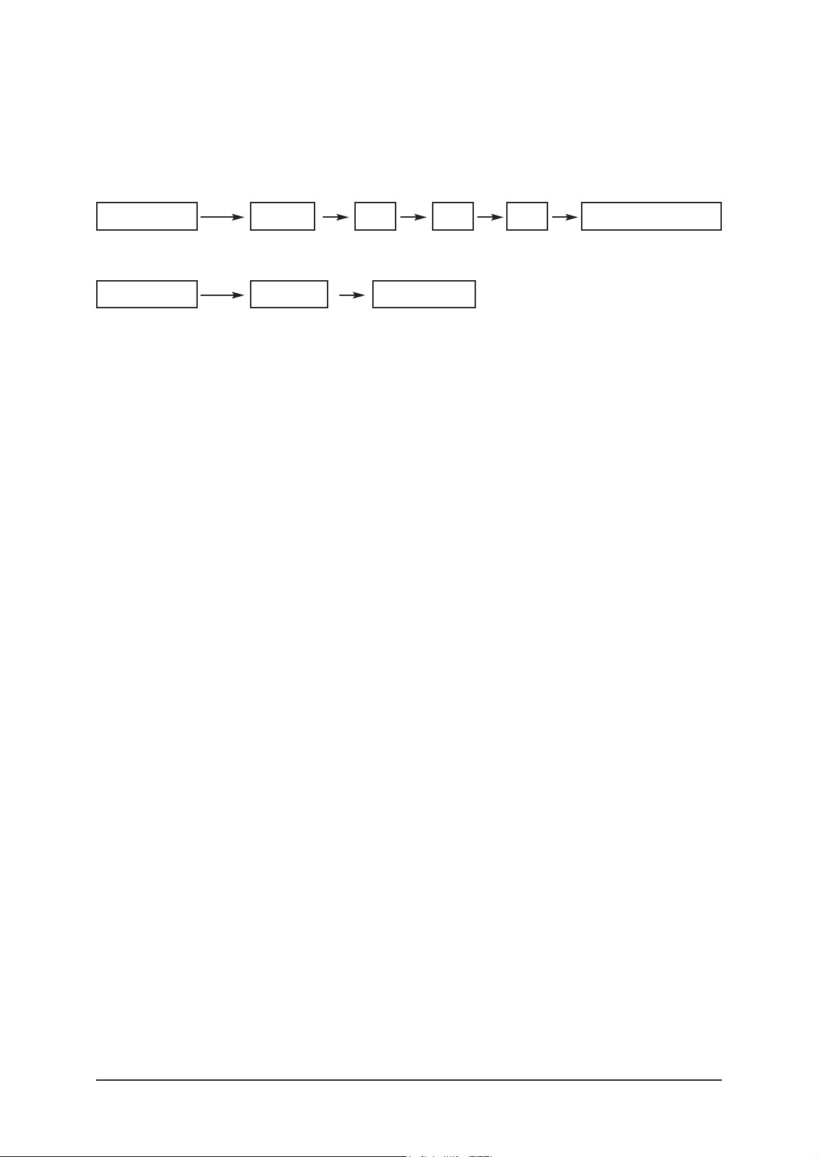
3-2-1 Entering Factory Mode
1. To enter "Service Mode" Press the remote -control keys in this sequence :
- If you do not have Factory remote - control
- If you have Factory remote - control
- The buttons are active in the service mode.
1. Remote - Control Key : Power, Arrow Up, Arrow Down, Arrow Left
Arrow Right, Menu, Enter, Number Key(0~9)
2. Function - Control Key : Power, CH +, CH -, VOL +, VOL -,
Menu, TV/VIDEO(Enter)
Power OFF 1 8 2 Power OnMUTE
PICTURE ON
FACTORY
DISPLAY
3 Alignments and Adjustments
3-3
3-3 Factory Data
1. Calibration
2. Option Table XXXX XXXX
3. W/B
4. W/B Movie
5. MTK8202
6. FBE2 Option
7. Sound
8. YC Delay
9. Adjust
10. Bus Stop
11. Password 80 80 80 80
12. Checksum 0000
13. Dynamic Contrast
14. Spread Spectrum
15. Reset
HDCP Write Success..
T_BDPMNSA-1000 Aug 04 2006 16:41:30 ------------------- (Main Micom Ver)
Month/ Day / Year / Hour/ Min./Sec.
Panel On Time(Hour) XXXXX
TV Air 2 XX
1. Calibration
1) AV Calibration
2) DTV Calibration
3) PC Calibration
4) HDMI Calibration
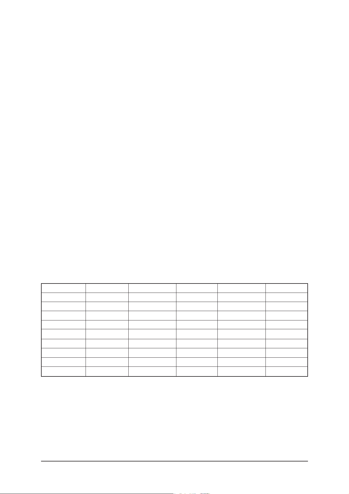
2. Option Byte
inch Option 32 Carrier Mute ON Shop Mode OFF
Gamma AUO Auto FM ON Debug OFF
Panel option AUO_AMVA High Dev. OFF Dynamic Contrast OFF
2HDMI OFF ACR OFF V-Chip OFF
Brt,Sensor OFF Dynamic CE ON
EnergySave ON Dynamic Dimming ON
LBE/FBE OFF Color System Manual
FRC(Micronas) OFF Auto Power ON
FRC(Samsung) OFF Magazine LNA OFF
LNA OFF V-Chip Area US

3 Alignments and Adjustments
3-4
3. White Balance
Sub Brightness 104 104 104
R-Offset 122 122 122
G-Offset 128 128 128
B-Offset 129 129 129
Sub Contrast 165 155 --> 140 155 --> 140
R-Gain 137 137 137
G-Gain 128 128 128
B-Gain 136 136 136
1. Calibration
2. Option Table
AV Calibration EXE
DTV Calibration EXE
PC Calibration EXE
HDMI Calibration EXE
Inch Option 26" 32" 40"
Gamma AUO AUO AMLCD
Panel Option AUO AUO_AMVA AMLCD_INT
2Hdmi OFF OFF OFF
Brt. Sensor OFF OFF OFF
EnergySave ON ON ON
LBE/FBE OFF OFF OFF
FRC(Micronas) OFF OFF OFF
FRC(Samsung) OFF OFF OFF
LNA OFF OFF OFF
Carrier Mute ON ON ON
Auto FM ON ON ON
High Deviation OFF OFF OFF
ACR OFF OFF OFF
Dynamic CE ON ON ON
Dynamic Dimming ON ON ON
Color System Manual Manual Manual
Auto Power ON ON ON
Magazine LNA OFF OFF OFF
V-Chip Area US US US
Shop Mode OFF OFF OFF
Debug OFF OFF OFF
Dynamic Contrast OFF OFF OFF
V-Chip OFF OFF OFF

3 Alignments and Adjustments
3-5
4. SVP-PX
ComB Filter Y-Filter 80H
Sharpness H2Gain 00H
H4Gain 0CH
V2Gain 00H
V4Gain 0CH
Sr2Gain 00H
Sr4Gain 08H
Sl2Gain 00H
Sl4Gian 08H
PeaKTh1 03H
PeaKTh2 33H
PeaKTh3 45H
NR Y_NR_OFF 80H
C_NR_OFF 80H
Y_NR_ON 80H
C_NR_ON 80H
RGB Calibration R-Offset 23H
G-Offset 23H
B-Offset 23H
R-Gain 9BH
G-Gain 9BH
B-Gain 9BH
ADC Calibration TCD3 Contrast 6AH
TCD3 Brightness 26H
TCD3 CR 80H
TCD3 CB 80H
TCD3 Delay 00H
Analog Y Offset 40H
Analog PB Offset 80H
Analog PR Offset 80H
Analog Y Gain D6H
Analog PB Gain FEH
Analog PR Gain FEH
Black Level 00H
Svp Brightness 00H
3 Alignments and Adjustments
3-6
low high delta
Calibration Target AV ADC 17H D5H 04H
COMP ADC 0FH EBH 02H
PC ADC 17H D5H 04H
ALL RGB 00H DDH 08H
Color Management Skin Direction Reddish
Skin Enhane 40H
5. Option block
EXE
6. STV8258/STA323W
Ch1 Volume 40H
Ch2 Volume 40H
Stereo Pilot H 23H
Stereo Pilot L 10H
Sap Pilot H 80H
Sap Pilot L 60H
SQTH 70H
CETH 10H
AV Delay 55H
Comp delay 32H
HDMI Delay 32H
PC Delay 32H
L1 Att/Rel Thres 7F
7. Y/C Delay
RF PAL-M 77H
RF PAL-N 64H
RF NTSC 63H
AV PAL-M 76H
AV PAL-N 76H
AV NTSC 54H
S-VIDEO PAL-M 77H
S-VIDEO PAL-N 77H
S-VIDEO NTSC BBH
Component 88H
PC 88H
HDMI 88H

3 Alignments and Adjustments
3-7
8. Adjust
Video Mute Time 10
Vol Curve Large
Melody Volume 4
Ana_Dimm_Max FEH
LNA PLUS RFDB-1 Level 2
RFDB-2 Level 5
RFDB-3 Level 9
RFDB-4 Level 24
Hotel Option Hotel Mode OFF
Power On Channel 1
Power On Volume 10
Max Volume 100
Local Key Lock OFF
Power On Source RF
9. I2C Check
EXE
10. W/B MOVIE
WB Movie OFF
Color Mode Movie
W1 R Gain 157
W1 B Gain 76
W1 R Offset 119
W1 B Offset 138
W2 R Gain 142
W2 B Gain 48
W2 R Offset 129
W2 B Offset 143
Movie Contrast 80
Movie Brightness 65
Movie Color 35
Movie Sharpness 35
Movie Color Tone Warm2
3 Alignments and Adjustments
3-8
11. Checksum
18EA
12. Reset
EXE
13. Spread Spectrum
Spectrum ON
Delta 3
Positive 8
Negative 2

3 Alignments and Adjustments
3-9
3-4 Ser vice Adjustment
3-4-1 White Balance - Calibration
If picture color is wrong, do calibration first.
Equipment : CA210, Patten : chess pattern
Execute calibration in Factory Mode
Source AV : PAL composite, Component : 1280*720/60Hz
PC : 1024*768/60Hz
3-4-2 White Balance - Adjustment
If picture color is wrong, check White Balance condition.
Equipment : CA210, Patten : Toshiba
Adjust W/B in Factory Mode
Sub brightness and R/G/B Offset controls low light region
Sub contrast and R/G/B Gain controls high light region
Source AV : PAL composite, Component : 1280*720/60Hz
HDMI[DVI] : 1280*720/60Hz
W/B Patten
[ Test Pattern : MSPG-945 Series Pattern #92 ]
*Color temperature
1500K +/-500, -6 ~-20 MPCD
*Color coordinate
H/L : 267/263 +/- 2 35.0 Ft +/- 2.0Ft
L/L : 270/260 +/- 3 1.5 Ft +/- 0.2Ft
( chess patten )

3 Alignments and Adjustments
3-10
3-4-3 Conditions for Measurement
1. On the basis of toshiba ABL pattern : High Light level (57 IRE)
- INPUT SIGNAL GENERATOR : MSPG-925LTH
* Mode NO 1 : 744X484@60 Hz
NO 2 : 744X484@60 Hz
NO 6 : 1280X720@60 Hz
NO 21 : 1024X768@60 Hz
* Pattern NO 36 : 16 Color Pattern
NO 16 : Toshiba ABL Pattern
NO 92 : W/B Pattern
2. Optical measuring device : CA210 (FL)
Please use the MSPG-925 LTH generator for model
LE26M51B/LE32M51B/LE40M51B/LE46M51B
.
3-4-4 Method of Adjustment
1. Adjust the white balance of AV, Component and DVI Modes.
(AV Component)
a) Set the input to the mode in which the adjustment will be made
(RF DTV PC DVI).
* Input signal - VIDEO Mode : Model #2 (744*484 Mode), Pattern #16
- DTV,DVI Mode : Model #6 (1280*720 Mode), Pattern #16
- HDMI Mode: Model #6(1280*720 Mode), Pattern #16
b) Enter factory color control, confirm the data.
c) Adjust the low light. (Refer to table 1, 2 in adjustment position by mode)
- Adjust sub - Brightness to set the 'Y' value.
- Adjust red offset ('x') and blue offset ('y') to the color coordinates.
* Do not adjust green offset data.
d) Adjust the high light. (Refer to table 1, 2 in adjustment position by mode)
- Adjust red gain ('x') and blue gain ('y') to the color coordinates.
* Do not adjust the green gain and sub-contrast (Y) data.
Picture 4-2 W/B Patten

3 Alignments and Adjustments
3-11
Picture 4-3 W/B Patten
3 Alignments and Adjustments
3-12
3-5 Software Upgrade
3-5-1 How to Update Flash ROM (with RS-232C Cable)
1. Installthe Flash Downloader
ConnectSet(Service Jack)and Jig Cable to execute Program Update.
2. Turn on the Set (or on Stand by mode)
- Run "MTKtool"
3. Turn off (= AC Power off) the Set (waiting a few seconds) and turn on again.
- Click Reset
- Choose MT8202 (1)
- Select Com Port (2) (Auto Detect)
- Select Bin file, by browse (3)
- Click Upgrade button (4)
3 Alignments and Adjustments
3-13
3-5-2 How to Update Flash ROM (with UART JIG)
¡Ø In the usual cases, Update S/W by using RS-232C Cable.
If some problems occur under this condition, update S/W by using UART JIG.
You can use UART JIG with USB Connection.
Install in your PC before using the JIG
Connect 4P Lead connector to Main Board(CN501)

3 Alignments and Adjustments
3-14
* Pin Assignment
Turn on the Set (or on Stand by mode)
- Run "MTKtool"
When you run "MTKtool", this Program can detect USB port automatically
Choose USB interface and Update S/W as RS-232C case.

4 Troubleshooting
4-1
4 Troubleshooting
4-1 First Checklist for Troubleshooting
1. Check the various cable connections first.
- Check to see if there is a burnt or damaged cable.
- Check to see if there is a disconnected cable connection or a connection is too loose.
- Check to see if the cables are connected according to the connection diagram.
2. Check the power input to the Main Board.
3. Check the voltage in and out between the SMPS Main Board, between the SMPS
INVERTER Board, and between the Main LVDS Boards.

4 Troubleshooting
4-2
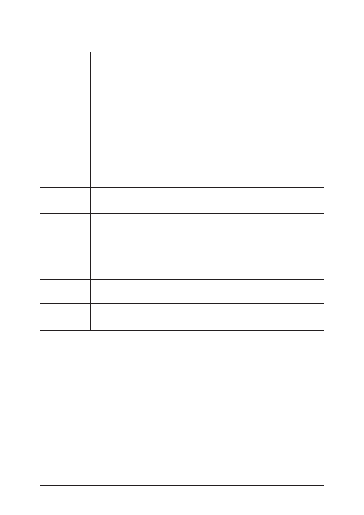
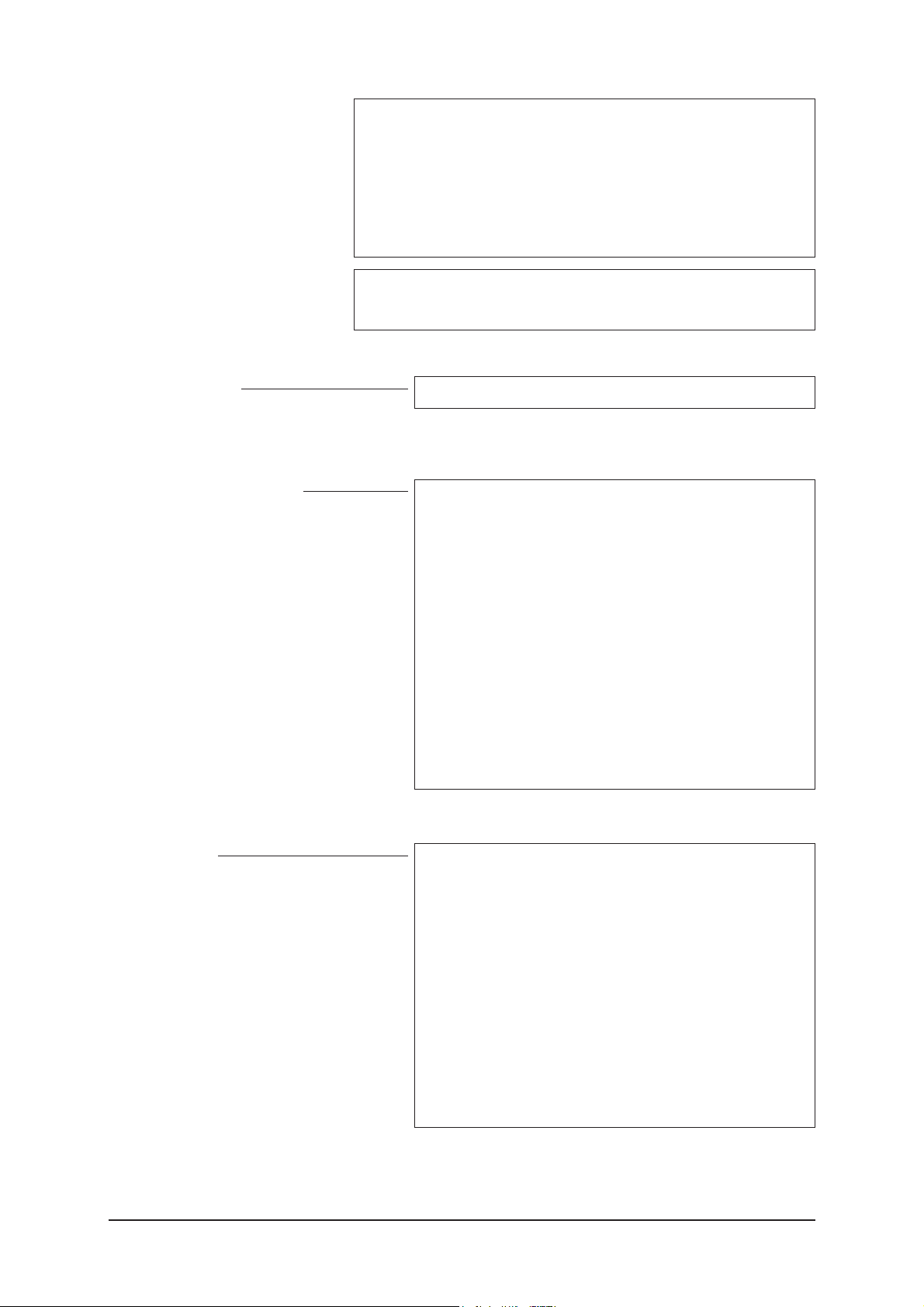
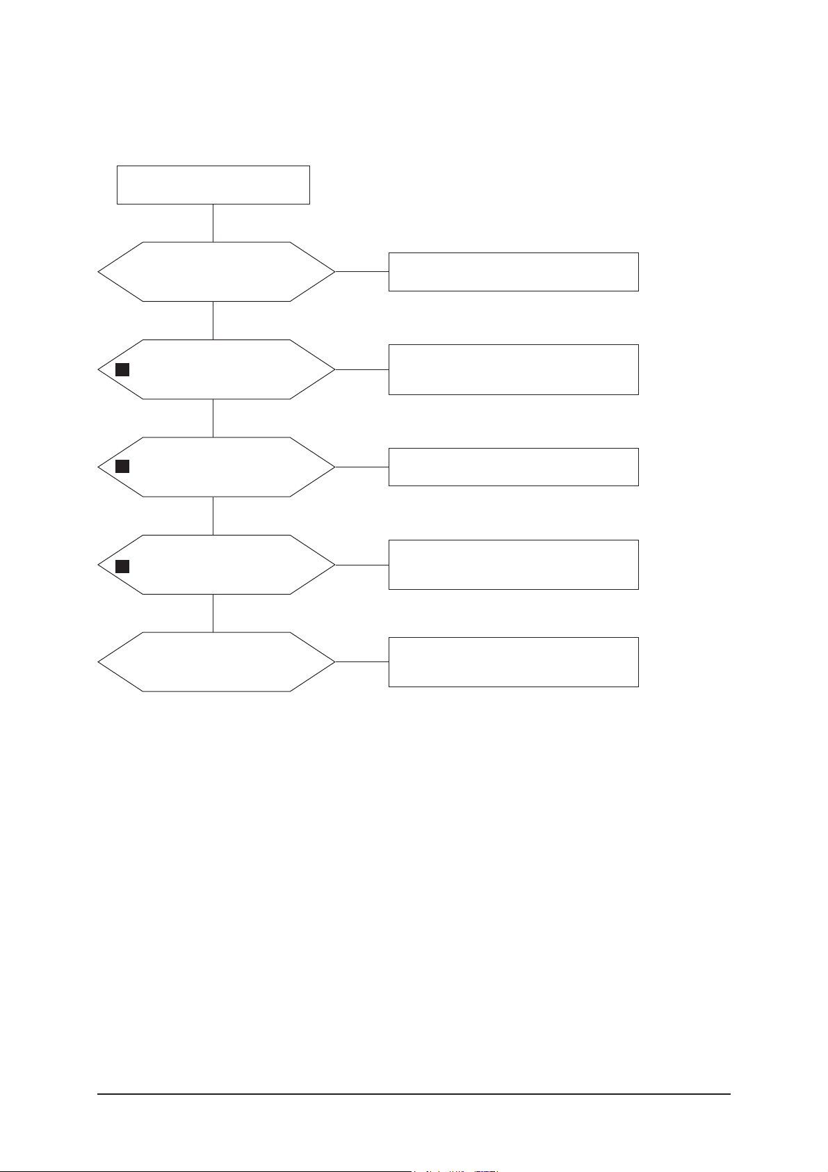
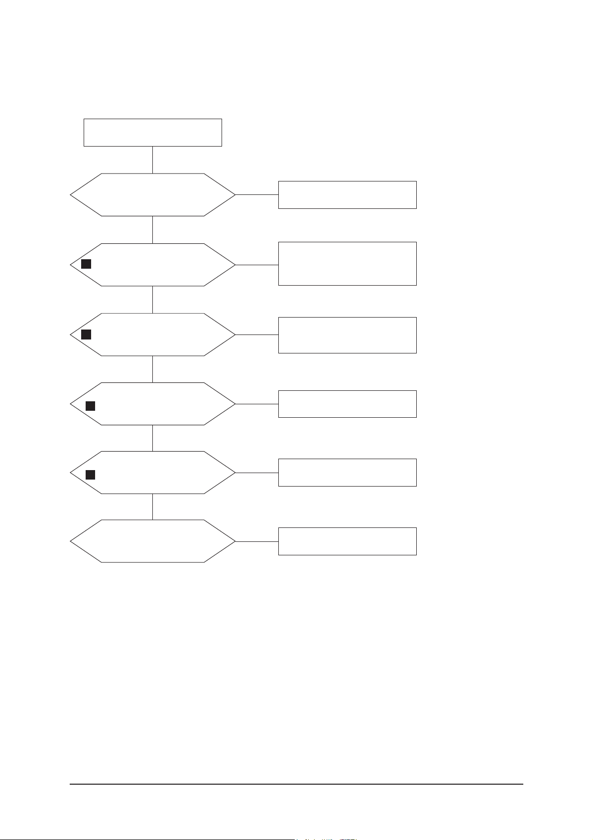
4-2-1 No Power
4-2 Checkpoints by Error Mode
Does proper DC
A3.3V,A1.8Vappear at C126,
C156?
Check IC104, IC107 Change the
Main Ass'y
Yes
Yes
Yes
No
Check a connection a power cable.
P/N : BN39-00802A
BN39-00802B(40")
Change the Main Power Ass'y
23" : BN44-00158A
26" : BN44-00156A
32" : BN44-00156A
40" : BN44-00167A/00165A
No
Does proper DC
B9V,B3.3V_8202/B3.3VD,
B2.5V_8202 appear at
C103,C132, C145?
Check a IC809, IC802.
Change a main PCB ass'y.
Yes
No
Does proper DC 5V, 3.3V,
1.8V appear at C811, C853,
C833?
Check IC101, IC105, IC106 Change the
Main Ass'y
Yes
Does proper DC B3.3FB,
B1.2FB, B1.8VD appear at
C179_FBE, C182_FBE, C159?
Check IC110_FBE, IC111_FBE, IC109
Change the Main Ass'y
No
No
Yes
Yes
Does proper DC B3.3VD
appear at D8014?
Check IC8001
Change the Main Ass'y
No
A power is supplied to set?
Check a other function(No picture part)
Replace a LCD Panel
23" : BN07-00365A
26" : BN07-00254A
32" : BN07-00385A
40" : BN07-00387A
No
LAMP off, power indicator
LED red color?
Does proper Satand-By DC
A5V appear at C127
Does proper Main DC B12V,
B5V, B12VS appear at C104,
BD105, C119?
Does proper Inverter DC 24V
appear at CNM801 in SMPS
4 Troubleshooting
4-3
4-2-2 No Video (Analog PC Signal)
Check the PC source and
check the connection of
DSUB?
Input an analog PC signal.
check the connected cable.
Yes
Does the signal appear at
#R25, T25, T24, U24, V25,
V26(R,G,SOG,B,V,H) of
IC602?
Check JA306, PC cable.
Change the PC cable.
Change the main PCB Ass'y.
Yes
Power Indicator is off.
Lamp on, no video.
No
No
1
Does the digital data appear at
output of R916_FBE ~
R921FBE?
Check IC602.
Change the main PCB Ass'y.
Yes
Does the digital data appearat
output of R1001_FBE ~
R1017_FBE?
Check IC 901_FBE
Change the main PCB Ass'y.
Yes
No
No
2
3
Yes
Check the LVDS cable?
Replace the LCD panel?
Please, call to Samsung Co. LTD
No

4 Troubleshooting
4-4
WAVEFORMS
1 2
PC Input (V-Sync, H-Sync)
3
LVDS Out (CLK +/-)
4 Troubleshooting
4-5
4-2-3 No Video (HDMI - Digital Signal)
Check the HDMI source and
check the connection of
HDMI cable?
Input a HDMI signal.
check the connected cable.
Yes
Does the signal appear at
R461,R464,R457,R458,R454,
R456,R467-R474?
Check JA801, JA802,
HDMI cable.
Change the HDMI cable.
Change the main PCB Ass'y
Yes
Does the digital data appear
at output of R738 ~ R745?
Check IC405
Change the main PCB Ass'y.
Yes
Does the digital data appear
at output of R916_FBE ~
R921FBE?
Check IC601.
Change the main PCB Ass'y.
Yes
Power Indicator is off.
Lamp on, no video.
No
No
No
No
4
5
2
Yes
Does the digital data appearat
output of R1001_FBE ~
R1017_FBE?
Check IC 901_FBE
Change the main PCB Ass'y.
No
3
Yes
Check the LVDS cable?
Replace the LCD panel?
Please, call to Samsung Co. LTD
No
 Loading...