

Samsung LN26D450G1M, LN32D430G3DXZX, LN32D450G1M, LN32D450G1G Service Manual
SERVICE
Manual
TFT-LCD TV Contents
1. Precautions
2. Product specications
3. Disassembly and Reassembly
4. Troubleshooting
5. Wiring Diagram
LCD-TV
LN**D450G1G_M
Front Design : ToC Red Black Stand : Round
Chassis : U61A
Model : LN26D450G1G
LN26D450G1M
LN32D450G1G
LN32D450G1M

Contents
1. Precautions .............................................................................................................. 1-1
1-1. Safety Precautions ......................................................................................................... 1-1
1-2. Servicing Precautions ..................................................................................................... 1-2
1-3. Electrostatically Sensitive Devices (ESD) Precautions .................................................. 1-2
1-4. Installation Precautions .................................................................................................. 1-3
2. Product specications ............................................................................................ 2-1
2-1. Model Comparison ......................................................................................................... 2-1
2-2. Feature & Specications ................................................................................................. 2-2
2-3. Specication Comparison to Old Models ........................................................................2-6
2-4. Detail Factory Option ...................................................................................................... 2-7
2-5. Media Play ...................................................................................................................... 2-8
2-6. Accessories .................................................................................................................. 2-11
3. Disassembly and Reassembly ............................................................................... 3-1
3-1. Disassembly and Reassembly ....................................................................................... 3-1
3-2. Stand assembly .............................................................................................................. 3-5
4. Troubleshooting ...................................................................................................... 4-1
4-1. Troubleshooting .............................................................................................................. 4-1
4-2. Function ........................................................................................................................ 4-24
4-3. Factory Mode Adjustments ........................................................................................... 4-25
4-4. White Balance - Calibration .......................................................................................... 4-37
4-5. Servicing Information .................................................................................................... 4-40
4-6. Software Upgrade ......................................................................................................... 4-41
4-7. Rear Cover Dimension ................................................................................................. 4-42
5. Wiring Diagram ........................................................................................................ 5-1
5-1. Wiring Diagram ............................................................................................................... 5-1
5-2. Connector ....................................................................................................................... 5-2
5-3. Connector Functions ...................................................................................................... 5-4
5-4. Cables ............................................................................................................................ 5-4

This Service Manual is a property of Samsung Electronics Co.,Ltd.
Any unauthorized use of Manual can be punished under applicable
International and/or domestic law.
© 2011 Samsung Electronics Co.,Ltd.
All rights reserved.
Printed in Korea
1-1
1. Precautions
1. Precautions
1-1. Safety Precautions
Follow these safety, servicing and ESD precautions to prevent damage and to protect against potential hazards such as
electrical shock.
1-1-1. Warnings
For continued safety, do not attempt to modify the circuit board.1.
Disconnect the AC power and DC power jack before servicing.2.
1-1-2. Servicing the LCD TV
When servicing the LCD TV, Disconnect the AC line cord from the AC outlet.1.
It is essential that service technicians have an accurate voltage meter available at all times. 2.
Check the calibration of this meter periodically.
1-1-3. Fire and Shock Hazard
Before returning the LCD TV to the user, perform the following safety checks:
Inspect each lead dress to make certain that the leads are not pinched or that hardware is not lodged between the 1.
chassis and other metal parts in the LCD TV.
Inspect all protective devices such as nonmetallic control knobs, insulating materials, cabinet backs, adjustment and 2.
compartment covers or shields, isolation resistorcapacitor networks, mechanical insulators, etc.
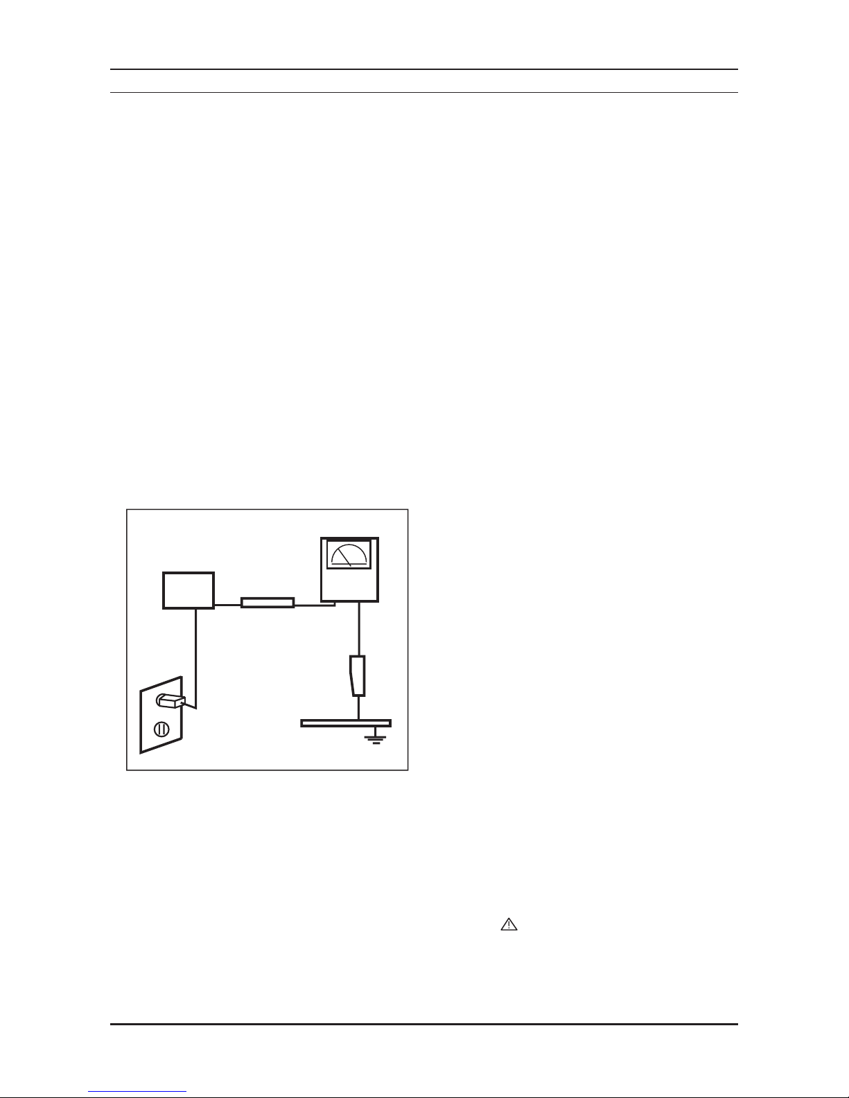
Leakage Current Hot Check (Figure 1-1): 3.
WARNING : Do not use an isolation transformer during this test.
Use a leakage current tester or a metering system that complies with American National Standards Institute (ANSI
C101.1, Leakage Current for Appliances), and Underwriters Laboratories (UL Publication UL1410, 59.7).
With the unit completely reassembled, plug the AC line cord directly into a 120V AC outlet. With the unit’s AC switch 4.
rst in the ON position and then OFF, measure the current between a known earth ground (metal water pipe, conduit,
etc.) and all exposed metal parts, including: metal cabinets, screwheads and control shafts.
The current measured should not exceed 0.5 milliamp.
Reverse the power-plug prongs in the AC outlet and repeat the test.
1-1-4. Product Safety Notices
Some electrical and mechanical parts have special safetyrelated characteristics which are often not evident from visual
inspection. The protection they give may not be obtained by replacing them with components rated for higher voltage,
wattage, etc. Parts that have special safety characteristics are identied by on schematics and parts lists. A substitute
replacement that does not have the same safety characteristics as the recommended replacement part might create
shock, re and / or other hazards. Product safety is under review continuously and new instructions are issued whenever
appropriate.
DEVICE
UNDER
TEST
(READING SHOULD)
NOT BE ABOVE 0.5mA
LEAKAGE
CURRENT
TESTER
TEST ALL
EXPOSED METAL
SURFACES
2-WIRE CORD
*ALSO TEST WITH
PLUG REVERSED
(USING AC ADAPTER
PLUG AS REQUIRED)
EARTH
GROUND
Figure 1-1. Leakage Current Test Circuit

1-2
1. Precautions
1-2. Servicing Precautions
WARNING: An electrolytic capacitor installed with the wrong polarity might explode.
Caution: Before servicing units covered by this service manual, read and follow the Safety Precautions section of this
manual.
Note: If unforeseen circumstances create conict between the following servicing precautions and any of the safety
precautions, always follow the safety precautions.
1-2-1. General Servicing Precautions
Always unplug the unit’s AC power cord from the AC power source and disconnect the DC Power Jack before 1.
attempting to:
(a) remove or reinstall any component or assembly, (b) disconnect PCB plugs or connectors, (c) connect a test
component in parallel with an electrolytic capacitor.
Some components are raised above the printed circuit board for safety. An insulation tube or tape is sometimes 2.
used. The internal wiring is sometimes clamped to prevent contact with thermally hot components. Reinstall all such
elements to their original position.
After servicing, always check that the screws, components and wiring have been correctly reinstalled. Make sure that 3.
the area around the serviced part has not been damaged.
Check the insulation between the blades of the AC plug and accessible conductive parts (examples: metal panels, 4.
input terminals and earphone jacks).
Insulation Checking Procedure: Disconnect the power cord from the AC source and turn the power switch ON. 5.
Connect an insulation resistance meter (500 V) to theblades of the AC plug.
The insulation resistance between each blade of the AC plug and accessible conductive parts (see above) should be
greater than 1 megohm.
Always connect a test instrument’s ground lead to the instrument chassis ground before connecting the positive lead; 6.
always remove the instrument’s ground lead last.
1-3. Electrostatically Sensitive Devices (ESD) Precautions
Some semiconductor (solid state) devices can be easily damaged by static electricity. Such components are commonly
called Electrostatically Sensitive Devices (ESD). Examples of typical ESD are integrated circuits and some eld-effect
transistors. The following techniques will reduce the incidence of component damage caused by static electricity.
Immediately before handling any semiconductor components or assemblies, drain the electrostatic charge from your 1.
body by touching a known earth ground. Alternatively, wear a discharging wrist-strap device. To avoid a shock hazard,
be sure to remove the wrist strap before applying power to the LCD TV.
After removing an ESD-equipped assembly, place it on a conductive surface such as aluminum foil to prevent 2.
accumulation of an electrostatic charge.
Do not use freon-propelled chemicals. These can generate electrical charges sufcient to damage ESDs.3.
Use only a grounded-tip soldering iron to solder or desolder ESDs.4.
Use only an anti-static solder removal device. Some solder removal devices not classied as “anti-static” can generate 5.
electrical charges sufcient to damage ESDs.
Do not remove a replacement ESD from its protective package until you are ready to install it. Most replacement ESDs 6.
are packaged with leads that are electrically shorted together by conductive foam, aluminum foil or other conductive
materials.
Immediately before removing the protective material from the leads of a replacement ESD, touch the protective 7.
material to the chassis or circuit assembly into which the device will be installed.
Caution: Be sure no power is applied to the chassis or circuit and observe all other safety precautions.
Minimize body motions when handling unpackaged replacement ESDs. Motions such as brushing clothes together, 8.
or lifting your foot from a carpeted oor can generate enough static electricity to damage an ESD.

1-3
1. Precautions
1-4. Installation Precautions
For safety reasons, more than a people are required for carrying the product.1.
Keep the power cord away from any heat emitting devices, as a melted covering may cause re or electric shock.2.
Do not place the product in areas with poor ventilation such as a bookshelf or closet. The increased internal 3.
temperature may cause re.
Bend the external antenna cable when connecting it to the product. This is a measure to protect it from being exposed 4.
to moisture. Otherwise, it may cause a re or electric shock.
Make sure to turn the power off and unplug the power cord from the outlet before repositioning the product. Also check 5.
the antenna cable or the external connectors if they are fully unplugged. Damage to the cord may cause re or electric
shock.
Keep the antenna far away from any high-voltage cables and install it rmly. Contact with the highvoltage cable or the 6.
antenna falling over may cause re or electric shock.
When installing the product, leave enough space (0.4 m) between the product and the wall for ventilation purposes. 7.
A rise in temperature within the product may cause re.
2-1
2. Product specications
2. Product specications
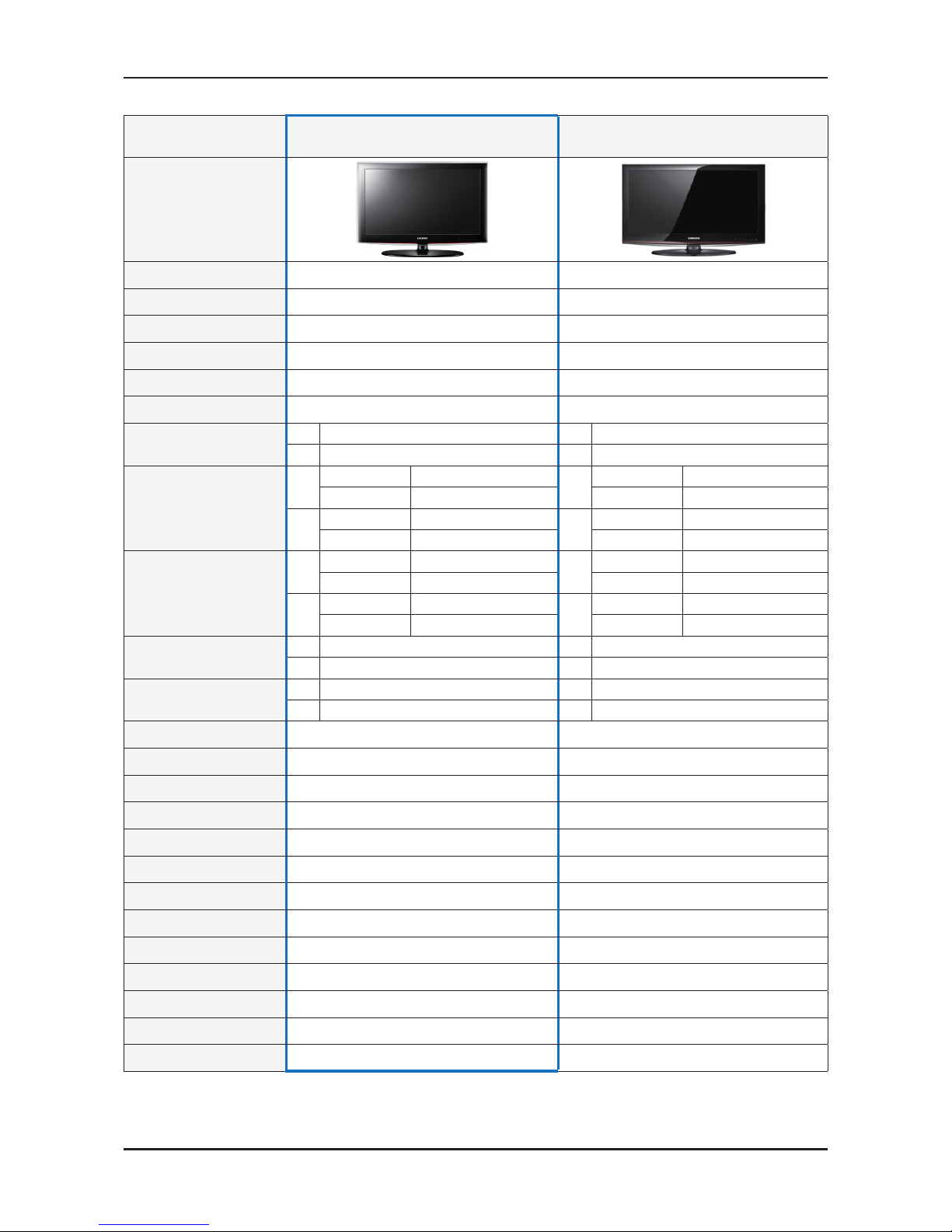
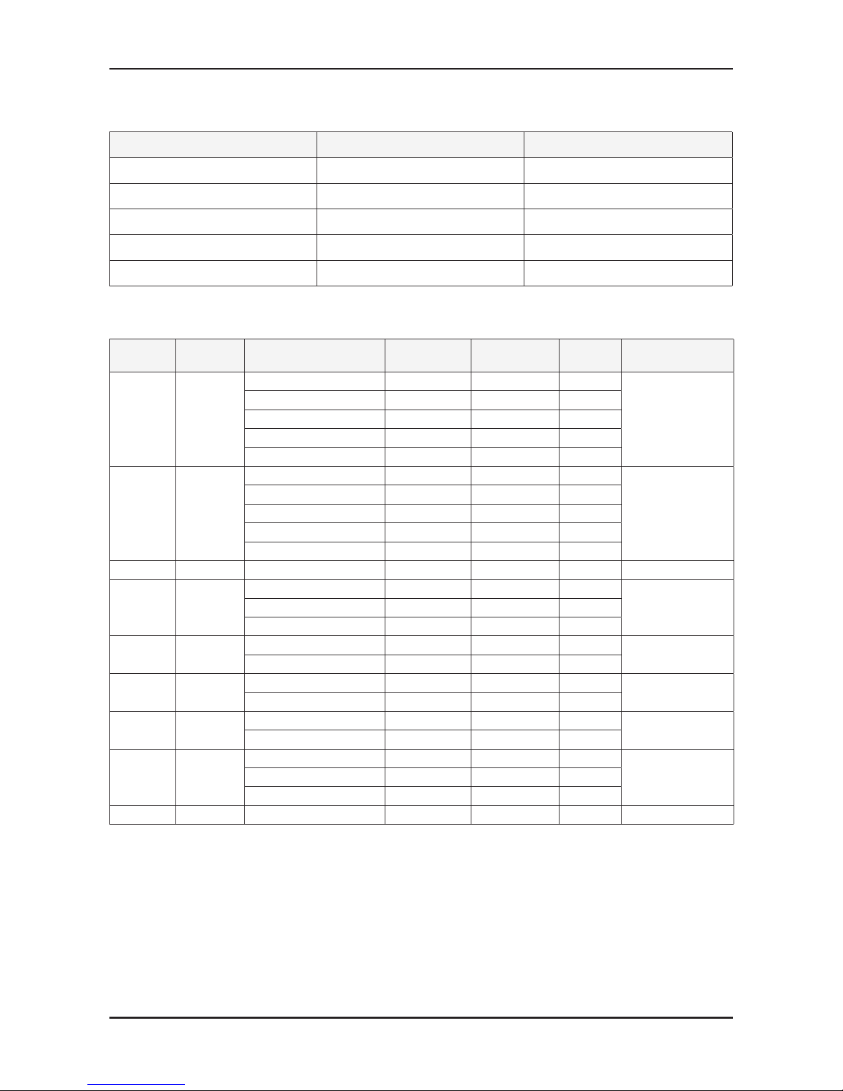
2-1. Model Comparison
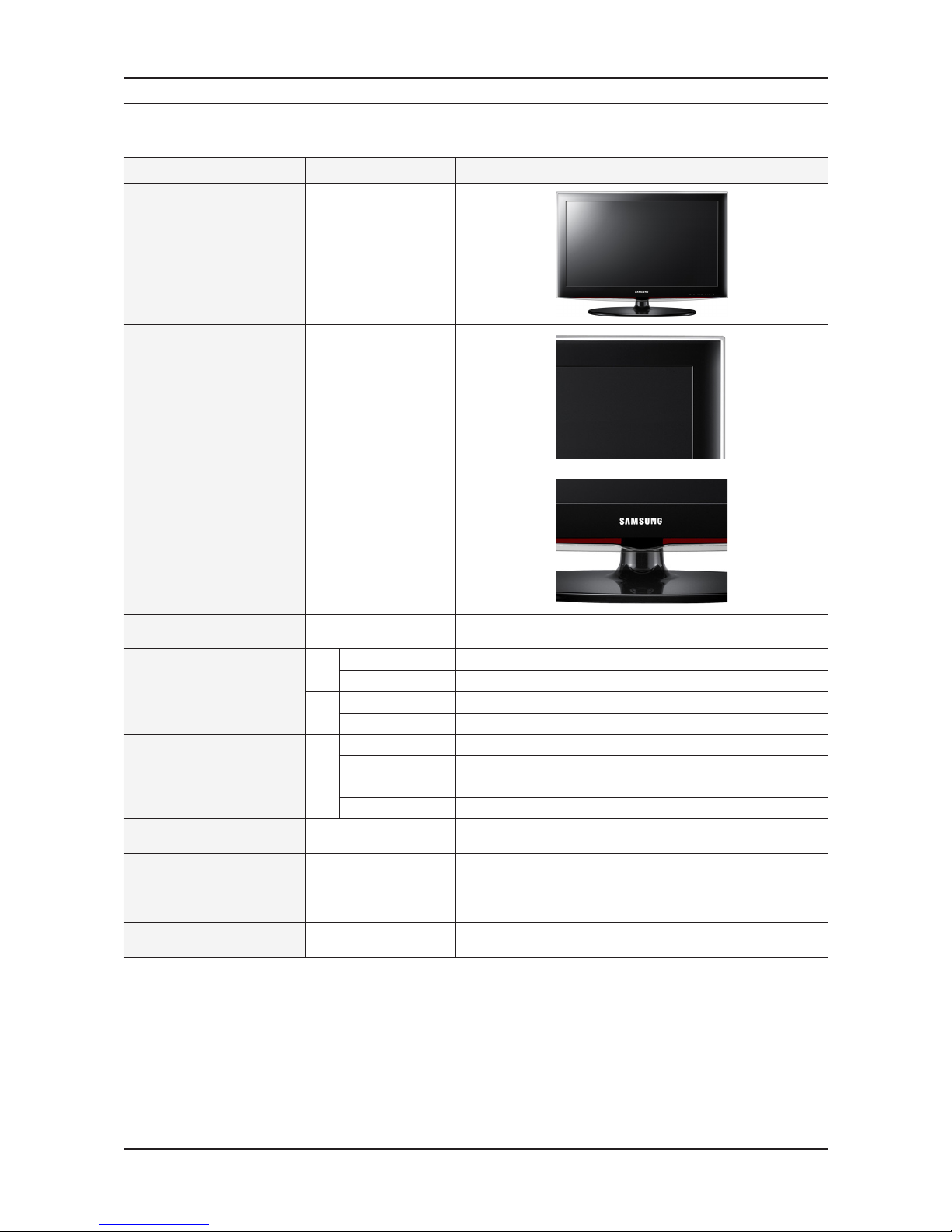
Model Inch LD450
Front View
All
Detail View
All
All
Front Color All ToC RED Black
Dimensions W x D x H
26"
With Stand 660.7 x 222.1 x 482.8 (mm) / 26 x 8.7 x 19 (inch)
Without Stand 660.7 x 78.6 x 435 (mm) / 26 x 3.1 x 17.1 (inch)
32"
With Stand 795.5 x 251.7 x 571.1 (mm) / 31.3 x 9.9 x 22.5 (inch)
Without Stand 795.5 x 80.4 x 510.3 (mm) / 31.3 x 3.2 x 20.1 (inch)
Weight
26"
With Stand 6.71 (kg) / 14.8 (lbs)
Without Stand 6.24 (kg) / 13.8 (lbs)
32"
With Stand 10.85 (kg) / 23.9 (lbs)
Without Stand 8.6 (kg) / 19 (lbs)
Speaker Output All Anti Glear
Antenna All None
HDMI
All
384 Mbtye
DLNA All Media Play (MOVIE), HDD
2-2
2. Product specications
2-2. Feature & Specications
Model LN26D450G1G (HD)
Feature
Digital-TV, RF, 2-HDMI, 2-Component, 2-A/V, 1-USB2.0, D-SUB ሪ
Brightness: 400 cd/m ሪ
2
High Contrast Ratio : 4,500:1 ሪ
Response Time: 8.5 ms ሪ
Specications
Item Description
LCD Panel 26 inch HD 60 Hz
Scanning Frequency
Horizontal: 60 KHz ~ 73 KHz (Automatic)
Vertical: 47 Hz ~ 63 Hz (Automatic)
Display Colors 16.7 M colors
Maximum Resolution
Horizontal: 1366 Pixels
Vertical: 768 Pixels
Input Signal
Analog 0.7 Vp-p ± 5 % positive at 75 Ω, internally terminated
Input Sync Signal H/V Separate, TTL, P. or N.
Maximum Pixel Clock Rate 74.25 MHz
Active Display
Horizontal / Vertical
575.8 (H) x 323.7 (V) (mm) / 22.7 (H) x 12.7 (V) (inch)
AC power voltage & Frequency AC 110 V ~ 120 V, 60 Hz
Power Consumption Under 85 W (Under 0.3 W, Stand by)
Dimensions Set (W x D x H)
With Stand 660.7 x 222.1 x 482.8 (mm) / 26 x 8.7 x 19 (inch)
Without Stand 660.7 x 78.6 x 435 (mm) / 26 x 3.1 x 17.1 (inch)
Weight
With Stand 6.71 (kg) / 14.8 (lbs)
Without Stand 6.24 (kg) / 13.8 (lbs)
TV System
Tuning Frequency Synthesize (Refer to detailed Frequency Table)
System ISDB-T, PAL-M / NTSC / PAL-N
Sound NTSC-M, Dolby Digital+
Environmental Considerations
Operating Temperature: 32˚F ~ 122˚F (0˚C ~ 50˚C)
Operating Humidity: 20 % ~ 90 %
Storage temperature: -4˚F ~ 140˚F (-20˚C ~ 60˚C)
Storage Humidity: 10 % ~ 90 %
Audio spec
MAX Internal Audio Output Power: Each 3 W (Left / Right) -
Equalizer: 5 band -
Output Frequency: RF: 20 Hz ~ 15.4 KHz -
AV / Componet / HDMI: 20 Hz ~ 20 KHz
Note: Dolby Digital+, Game Mode, Film Mode, Energy Saving, Anynet
+
2-3
2. Product specications
Model LN26D450G1M (HD)
Feature
Digital-TV, RF, 2-HDMI, 2-Component, 2-A/V, 1-USB2.0, D-SUB ሪ
Brightness: 400 cd/m ሪ
2
High Contrast Ratio: 4,500:1 ሪ
Response Time: 8.5 ms ሪ
Specications
Item Description
LCD Panel 26 inch HD 60 Hz
Scanning Frequency
Horizontal: 60 KHz ~ 73 KHz (Automatic)
Vertical: 47 Hz ~ 63 Hz (Automatic)
Display Colors 16.7 M colors
Maximum Resolution
Horizontal: 1366 Pixels
Vertical: 768 Pixels
Input Signal Analog 0.7 Vp-p ± 5 % positive at 75 Ω, internally terminated
Input Sync Signal H/V Separate, TTL, P. or N.
Maximum Pixel Clock Rate 74.25 MHz
Active Display
Horizontal / Vertical
575.8 (H) x 323.7 (V) (mm) / 22.7 (H) x 12.7 (V) (inch)
AC power voltage & Frequency AC 110 V ~ 120 V, 60 Hz
Power Consumption Under 85 W (Under 0.3 W, Stand by)
Dimensions Set (W x D x H)
With Stand 660.7 x 222.1 x 482.8 (mm) / 26 x 8.7 x 19 (inch)
Without Stand 660.7 x 78.6 x 435 (mm) / 26 x 3.1 x 17.1 (inch)
Weight
With Stand 6.71 (kg) / 14.8 (lbs)
Without Stand 6.24 (kg) / 13.8 (lbs)
TV System
Tuning Frequency Synthesize (Refer to detailed Frequency Table)
System DVB-T, PAL-N, M
Sound NTSC-M, Dolby Digital+
Environmental Considerations
Operating Temperature: 32˚F ~ 122˚F (0˚C ~ 50˚C)
Operating Humidity: 20 % ~ 90 %
Storage temperature: -4˚F ~ 140˚F (-20˚C ~ 60˚C)
Storage Humidity: 10 % ~ 90 %
Audio spec
MAX Internal Audio Output Power: Each 3 W (Left / Right) -
Equalizer: 5 band -
Output Frequency: RF: 20 Hz ~ 15.4 KHz -
AV / Componet / HDMI : 20 Hz ~ 20 KHz
Note: Dolby Digital+, Game Mode, Film Mode, Energy Saving, Anynet
+
2-4
2. Product specications
Model LN32D450G1G (HD)
Feature
Digital-TV, RF, 2-HDMI, 2-Component, 2-A/V, 1-USB2.0, D-SUB ሪ
Brightness: 400 cd/m ሪ
2
High Contrast Ratio: 4,000:1 ሪ
Response Time: 8.5 ms ሪ
Specications
Item Description
LCD Panel 32 inch HD 60 Hz
Scanning Frequency
Horizontal: 60 KHz ~ 73 KHz (Automatic)
Vertical: 47 Hz ~ 63 Hz (Automatic)
Display Colors 16.7 M colors
Maximum Resolution
Horizontal: 1366 Pixels
Vertical: 768 Pixels
Input Signal Analog 0.7 Vp-p ± 5 % positive at 75 Ω, internally terminated
Input Sync Signal H/V Separate, TTL, P. or N.
Maximum Pixel Clock Rate 74.25 MHz
Active Display
Horizontal / Vertical
697.7 (H) x 392.3 (V) (mm) / 27.5 (H) x 15.4 (V) (inch)
AC power voltage & Frequency AC 110 V ~ 120 V, 60 Hz
Power Consumption Under 110 W (Under 0.3 W, Stand by)
Dimensions Set (W x D x H)
With Stand 795.5 x 251.7 x 571.1 (mm) / 31.3 x 9.9 x 22.5 (inch)
Without Stand 795.5 x 80.4 x 510.3 (mm) / 31.3 x 3.2 x 20.1 (inch)
Weight
With Stand 10.85 (kg) / 23.9 (lbs)
Without Stand 8.6 (kg) / 19 (lbs)
TV System
Tuning Frequency Synthesize (Refer to detailed Frequency Table)
System ISDB-T, PAL-M / NTSC / PAL-N
Sound NTSC-M, Dolby Digital+
Environmental Considerations
Operating Temperature: 32˚F ~ 122˚F (0˚C ~ 50˚C)
Operating Humidity: 20 % ~ 90 %
Storage temperature: -4˚F ~ 140˚F (-20˚C ~ 60˚C)
Storage Humidity: 10 % ~ 90 %
Audio spec
MAX Internal Audio Output Power: Each 3 W (Left / Right) -
Equalizer: 5 band -
Output Frequency: RF: 20 Hz ~ 15.4 KHz -
AV / Componet / HDMI: 20 Hz ~ 20 KHz
Note: Dolby Digital+, Game Mode, Film Mode, Energy Saving, Anynet
+

2-5
2. Product specications
Model LN32D450G1M (HD)
Feature
Digital-TV, RF, 2-HDMI, 2-Component, 2-A/V, 1-USB2.0, D-SUB ሪ
Brightness: 400 cd/m ሪ
2
High Contrast Ratio: 4,000:1 ሪ
Response Time: 8.5 ms ሪ
Specications
Item Description
LCD Panel 32 inch HD 60 Hz
Scanning Frequency
Horizontal: 60 KHz ~ 73 KHz (Automatic)
Vertical: 47 Hz ~ 63 Hz (Automatic)
Display Colors 16.7 M colors
Maximum Resolution
Horizontal: 1366 Pixels
Vertical: 768 Pixels
Input Signal Analog 0.7 Vp-p ± 5 % positive at 75 Ω, internally terminated
Input Sync Signal H/V Separate, TTL, P. or N.
Maximum Pixel Clock Rate 74.25 MHz
Active Display
Horizontal / Vertical
697.7 (H) x 392.3 (V) (mm) / 27.5 (H) x 15.4 (V) (inch)
AC power voltage & Frequency AC 110 V ~ 120 V, 60 Hz
Power Consumption Under 110 W (Under 0.3 W, Stand by)
Dimensions Set (W x D x H)
With Stand 795.5 x 251.7 x 571.1 (mm) / 31.3 x 9.9 x 22.5 (inch)
Without Stand 795.5 x 80.4 x 510.3 (mm) / 31.3 x 3.2 x 20.1 (inch)
Weight
With Stand 10.85 (kg) / 23.9 (lbs)
Without Stand 8.6 (kg) / 19 (lbs)
TV System
Tuning Frequency Synthesize (Refer to detailed Frequency Table)
System DVB-T, PAL-N, M
Sound NTSC-M, Dolby Digital+
Environmental Considerations
Operating Temperature: 32˚F ~ 122˚F (0˚C ~ 50˚C)
Operating Humidity: 20 % ~ 90 %
Storage temperature: -4˚F ~ 140˚F (-20˚C ~ 60˚C)
Storage Humidity: 10 % ~ 90 %
Audio spec.
MAX Internal Audio Output Power: Each 3 W (Left / Right) -
Equalizer: 5 band -
Output Frequency: RF: 20 Hz ~ 15.4 KHz -
AV / Componet / HDMI: 20 Hz ~ 20 KHz
Note: Dolby Digital+, Game Mode, Film Mode, Energy Saving, Anynet
+
2-6
2. Product specications
2-3. Specication Comparison to Old Models
Model
LD4G (HD)
LN**D450G1G_M
LC4E / LC5F / LC5K
LN**C4*0E*M / LN**C530F1M / LN**C550J1M
Design
Display Type LCD TV LCD TV
Built-in Tuner O O
Resolution 1366 X 768 1366 X 768
LCD Panel TFT LCD Panel 60 Hz TFT LCD Panel 60 Hz
Screen Size 26" / 32" 26" / 32" / 37" / 40"
Picture ratio 16 : 9 16 : 9
Power Consumption
26" Under 85 W (Under 0.3 W, Stand by) 26"
Under 90 W (Under 0.3 W, Stand by)
32" Under 110 W (Under 0.3 W, Stand by) 32"
Under 120 W (Under 0.3 W, Stand by)
Dimensions (W x H x D)
26"
With Stand 26 x 8.7 x 19 (inch)
26"
With Stand
25.5 x 8.8 x 18.7 (inch)
Without Stand 26 x 3.1 x 17.1 (inch) Without Stand
25.5 x 3 x 17 (inch)
32"
With Stand 31.3 x 9.9 x 22.5 (inch)
32"
With Stand
26 x 9.7 x 22.8 (inch)
Without Stand 31.3 x 3.2 x 20.1 (inch) Without Stand
25.5 x 3 x 20.2 (inch)
Weight
26"
With Stand 14.8 (lbs)
26"
With Stand
14.7 (lbs)
Without Stand 13.8 (lbs) Without Stand
13.8 (lbs)
32"
With Stand 23.9 (lbs)
32"
With Stand
20.3 (lbs)
Without Stand 19 (lbs) Without Stand
19 (lbs)
Brightness
26" 400 (spec) 26"
450 (spec) / 450(marketing) Cd/m
2
32" 400 (spec) 32"
450 (spec) / 450(marketing) Cd/m
2
Contrast Ratio
26" 4,500 (spec) 26"
3,000 (spec) / 4,000:1 (marketing)
32" 4,000 (spec) 32"
3,500 (spec) / 6,000:1 (marketing)
Picture Enhacer HyperReal Engine (X5) HyperReal Engine (X4)
Equalizer 5 Band 5 Band
Auto Volume Control O O
Surround Sound Dolby Digital Plus Dolby Digital Plus / Pulse
Speaker Output 10 W + 10 W 10 W + 10 W
PIP O O
Double Window X X
Caption O O
Entertainment Mode X X
Game Mode O O
Energy Saving O O
Anynet+
O O
Antena
2 (Cable / Air) 2 (Cable / Air)
2-7
2. Product specications
2-4. Detail Factory Option
If you replace the main board with new one, please change the factory option as well. The options you must change ※
are “Type”.
Model Name LN26D450G1G LN32D450G1G LN26D450G1M LN32D450G1M
Panel
Vendor AML CMI AML AML
CODE BN07-00985A BN07-00951A BN07-00985A BN07-00978A
SPEC LTF260AP05 CM31B5A LTF260AP05 LTF320AP11
SMPS PD Board BN44-00438A BN44-00438A BN44-00438A BN44-00438B
Byte Item CHASSIS ASSY BN91-06406L BN91-06406P BN91-06406L BN91-06406P
0
FACTORY
Reset
PBA ASSY CODE BN94-04486A BN94-04487A BN94-04486A BN94-04487A
1 Type 26A6AH0C 32L6AH0C 26A6AH0C 32A6AH0C
2 Local set BRA_DTV, COLOMBIA
3 Model LD450
4 Tuner Auto / SEMCO SEC_ISDB, SI_TW
5 Ch Table - NONE
6 Front Color ON / OFF T-R-BLK

2-8
2. Product specications
2-5. Media Play
2-5-1. Using the Media Play Function
This function enables you to view and listen to photo (JPEG), audio les (MP3) and movie (MPEG) saved on a USB Mass
Storage Class (MSC) device.
Press the POWER button on the remote control or front panel. The TV is powered on.1.
Connect a USB device containing JPEG and / or MP3 and or/MPEG les to the usb jack (USB jack) on the side of the 2.
TV.
If you enter the Media Play mode with no USB device connected the message “No external storage device found. Check the connection status.” will appear. In this case, insert the USB device, exit the screen by pressing the MEDIA.P button on the
remote control and enter the MEDIA.P screen again. MTP (Media Transfer Protocol) is not supported. Certain types of USB
Digital camera and Audio devices may not be compatible with this TV. Media Play only supports USB Mass Storage Class
devices (MSC). MSC is a Mass Storage Class Bulk-Only Transport device. Examples of MSC are Thumb drives and Flash
Card Readers. Please connect directly to The USB port of your TV. If you are using a separate cable connection, there may
be a USB Compatibility problem. Before connecting your device to The TV, Please back up your les to prevent them from
damage or loss of data. SAMSUNG is not responsible for any data le damage or data loss. Do not disconnect The USB
device while it is loading. MSC supports MP3 and JPEG les, while a PTP device supports JPEG les only. The sequential
JPEG format is supported. Photo and Audio les must be named in English, French or Spanish. If not, the les can not be
played. Change the le names to English, French or Spanish if necessary. The higher The resolution of The image, The
longer it takes to display on the screen.
The maximum supported JPEG resolution is 15360 x 8640 pixels. For unsupported or corrupted les, The “Not supported File Format” message is displayed. Auto Chaptering function is supported.
Auto chaptering: When play movie, push enter key. you can see the snapshot of chapter, and you can skip to the ※
chapter using choice the snapshot.
2-9
2. Product specications
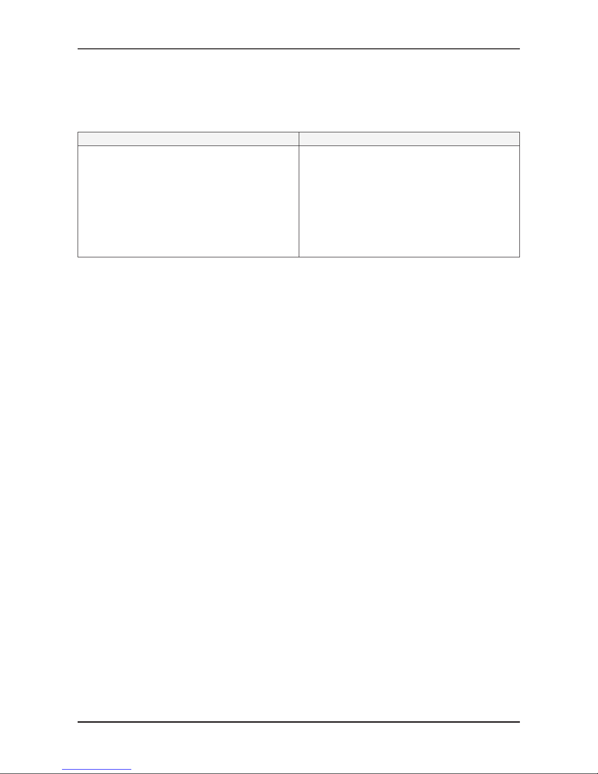
2-5-2 Supported Formats
Supported Subtitle Formats
Name File extension Format
MPEG-4 time-based text .ttxt text
SAMI .smi HTML
SubRip .srt string-based
SubViewer .sub string-based
Micro DVD .sub or .txt string-based
Supported Video Formats
File Container Video Codec Resolution
Frame rate
(fps)
Bit rate
(Mbps)
Audio Codec
*.avi
*.mkv
AVI
MKV
Divx 3.11 / 4.x / 5.1 / 6.0 1920 x 1080 6 ~ 30 8
MP3 / AC3 /
LPCM / ADPCM /
DTS Core
XviD 1920 x 1080 6 ~ 30 8
H.264 BP / MP / HP 1920 x 1080 6 ~ 30 25
MPEG4 SP / ASP 1920 x 1080 6 ~ 30 8
Motion JPEG 640 x 480 6 ~ 30 8
*.asf ASF
Divx 3.11 / 4.x / 5.1 / 6.0 1920 x 1080 6 ~ 30 8
MP3 / AC3 / LPCM
/ ADPCM / WMA
Divx 4.x / 5.1 / 6.0 1920 x 1080 6 ~ 30 8
XviD 1920 x 1080 6 ~ 30 8
MPEG4 SP / ASP 1920 x 1080 6 ~ 30 8
Motion JPEG 640 x 480 6 ~ 30 25
*.wmv ASF Window Media Video v9 1920 x 1080 6 ~ 30 25 WMA
*.mp4 MP4
H.264 BP / MP / HP 1920 x 1080 6 ~ 30 25
MP3 / ADPCM /
AAC
MPEG4 SP / ASP 1920 x 1080 6 ~ 30 8
XVID 1920 x 1080 6 ~ 30 8
*.3gp 3GPP
H.264 BP/MP / HP 1920 x 1080 6 ~ 30 25
ADPCM / AAC
MPEG4 SP / ASP 1920 x 1080 6 ~ 30 8
*.vro
VRO
VOB
MPEG2 1920 x 1080 24 / 25 / 30 30
AC3 / MPEG /
LPCM
MPEG1 1920 x 1080 24 / 25 / 30 30
*.mpg
*.mpeg
PS
MPEG1 1920 x 1080 24 / 25 / 30 30
AC3 / MPEG
/ LPCM /AAC
MPEG2 1920 x 1080 24 / 25 / 30 30
*.ts
*.tp
*.trp
TS
MPEG2 1920 x 1080 24 / 25 / 30 30
AC3 / AAC / MP3 /
DD+ / HE-AAC
H.264 1920 x 1080 6 ~ 30 25
VC1 1920 x 1080 6 ~ 30 25
*.rmvb RMVB RV 3.0 / RV4.0 1920 x 1080 30 10 RealAudio 6.9.10
2-10
2. Product specications
Other Restrictions
NOTE ※
If there are problems with the contents of a codec, the codec will not be supported. -
If the information for a Container is incorrect and the le is in error, the Container will not be able to play xcorrectly. -
Sound or video may not work if the contents have a standard Bitrate / Frame rate above the compatible Frame / Sec xlisted in the table above.
Video Decoder Audio codec
Supports up to H.264, Level 4.1 -
H.264 FMO / ASO / RS, VC1 SP / MP / AP L4 and AVCHD are not supported.
XVID, MPEG4 SP, ASP: -
Below 1280 x 720: 60 frame max -
Above 1280 x 720: 30 frame max -
H.263 is not supported. -
GMC 2 is not support. -
Only Samsung Techwin MJEPG is supported. -
Supports up to WMA 7, 8, 9, STD. -
WMA 9 PRO does not support 2 channel excess multi channel or lossless audio.
WMA sampling rate 22050 Hz mono is not supported. -
2-11
2. Product specications
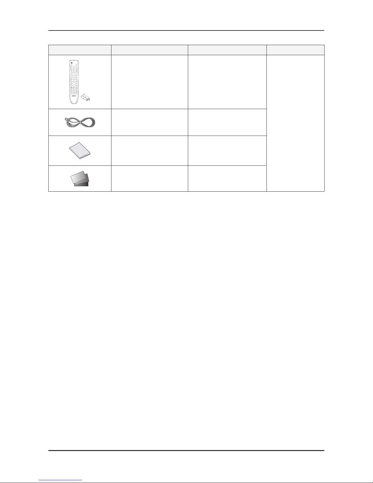
2-6. Accessories
Product Description Code. No Remark
Remote Control AA59-00486A
Samsung Electronics
Service center
Power Cord 3903-000601
Owner’s Instructions BN68-03375A
Warranty Card /
Safety Guide Manual
(Not available in all locations)
AA68-03242L
AA68-03533A
3-1
3. Disassembly and Reassembly
3. Disassembly and Reassembly
This section of the service manual describes the disassembly and reassembly procedures for the LCD TV.
WARNING: This LCD TV contains electrostatically sensitive devices. Use caution when handling these components.
3-1. Disassembly and Reassembly
Cautions: 1. Disconnect the LCD TV from the power source before disassembly.
2. Follow these directions carefully; never use metal instruments to pry apart the cabinet.
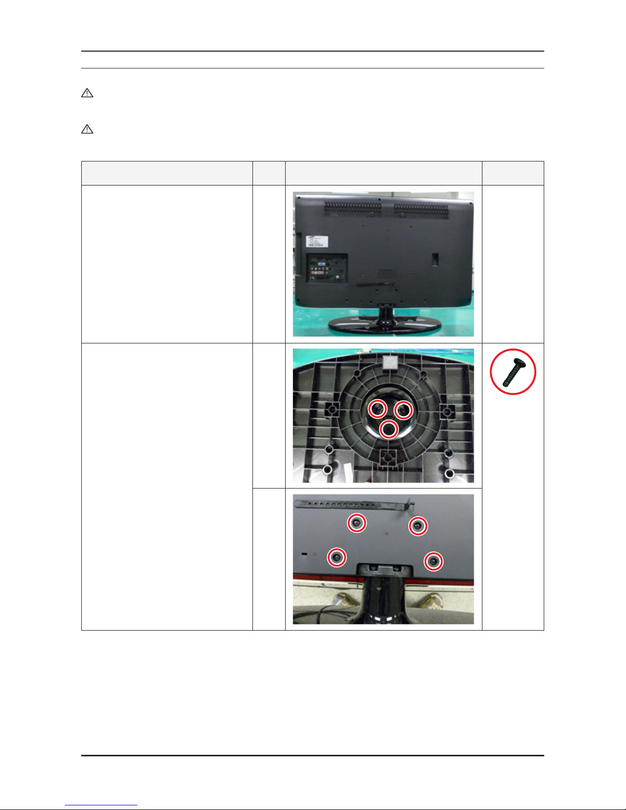
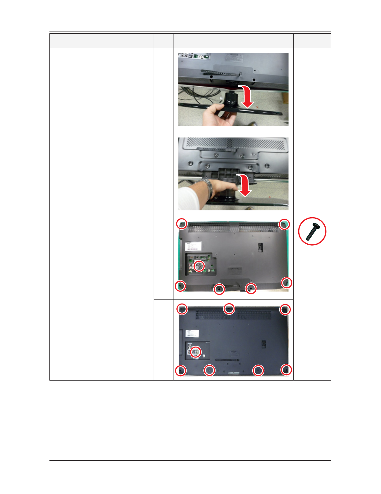
Description Inch Picture Description Screws
Place monitor face down on cushioned 1.
table.
Remove the screws from the stand. 2.
26": 3 EA
32": 4 EA
26"
6002-001294
32"
3-2
3. Disassembly and Reassembly
Description Inch Picture Description Screws
Remove stand.3.
26"
32"
Remove the screws of rear-cover. 4.
26": 7 EA
32": 8 EA
26"
6002-001294
32"
3-3
3. Disassembly and Reassembly
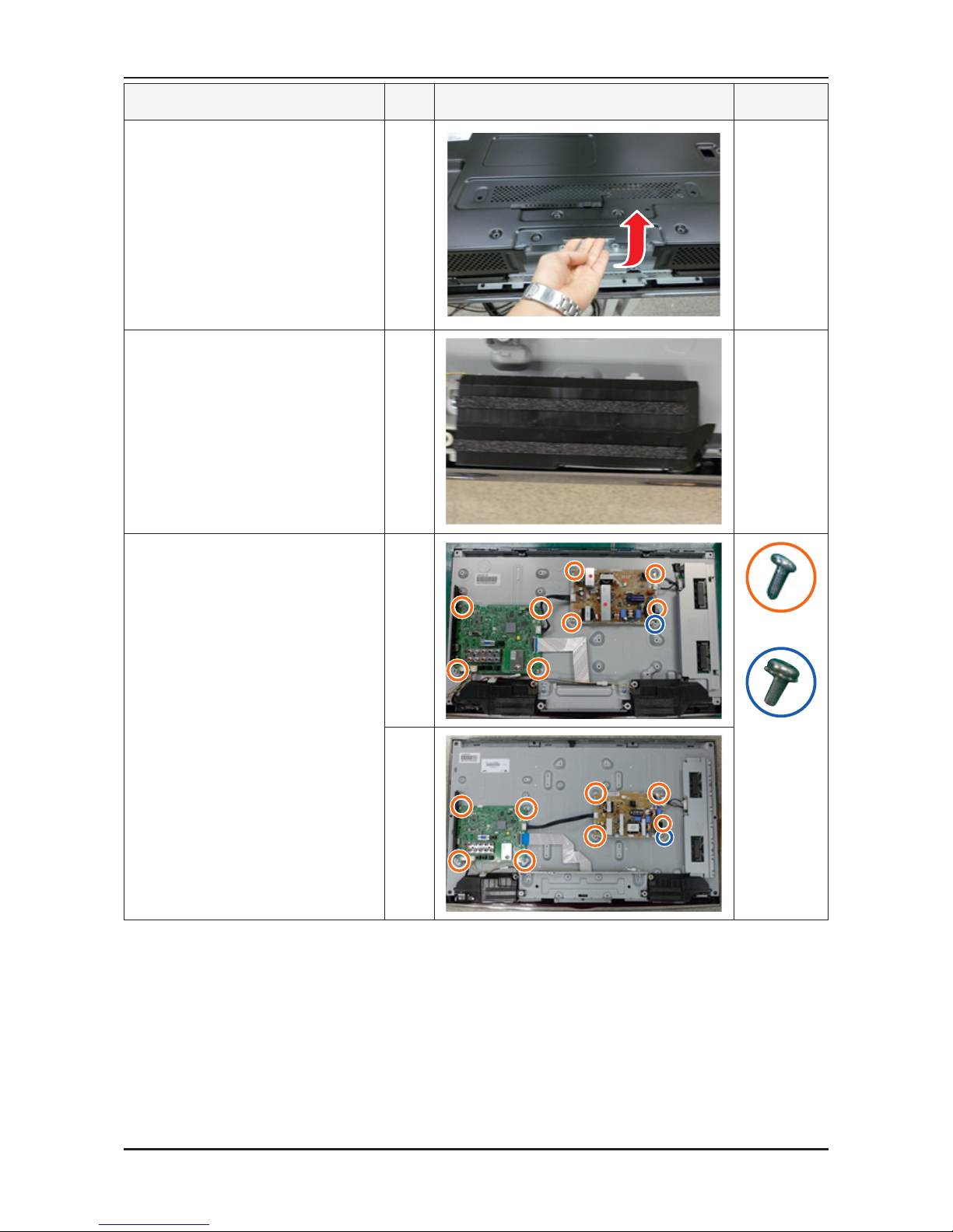
Description Inch Picture Description Screws
Lift up the rear-cover.5.
Remove the left and right speaker.6.
Remove the screws of main board. 7.
26", 32": 4 EA
Remove the screws of IP board.
26", 32": 5 EA
26"
6001-002284
6003-001439
32"
3-4
3. Disassembly and Reassembly
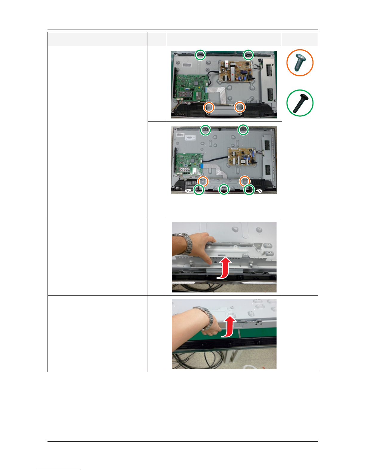
Description Inch Picture Description Screws
Remove the screws of stand link. 8.
26": 2 EA
32": 5 EA
Remove the screws of panel and front.
26" / 32": 2 EA.
screw is hidden under speaker
26"
6001-002284
6003-001003
32"
Lift up the stand link.9.
Lift up the panel.10.
Reassembly procedures are in the reverse order of disassembly procedures. ※
 Loading...