

Samsung LN37A450C1DXZA, LN32A450C1DXZA Owner’s Manual
imagine the possibilities
Thank you for purchasing a Samsung product.
To receive a more complete service, please
register your product at
www, samsung.com/global/reg ster
Model Serial No.
important Warranty information Regarding Television Format Viewing
Wide screen format LCD Displays (16:9, the aspect ratio of the screen width to height) are primarily designed to view wide screen format
full-motion video. The images displayed on them should primarily be in the wide screen 16:9 ratio format, or expanded to fill the screen
if your model offers this feature and the images are constantly moving. Displaying stationary graphics and images on screen, such as
the dark side-bars on nonexpanded standard format television video and programming, should be limited to no more than 5% of the total
television viewing per week.
Additionally, viewing other stationary images and text such as stock market reports, video game displays, station Iogos, web sites or
computer graphics and patterns, should be limited as described above for all televisions. Displaying stationary images that exceed the
above guidelines can cause uneven aging of LCD Displays that leave subtle, but permanent burned-in ghost images in the LCD picture. To
avoid this, vary the programming and images, and primarily display full screen moving images, not stationary patterns or dark bars.
On LCD models that offer picture sizing features, use these controls to view different formats as a full screen picture.
Be careful in the selection and duration of television formats used for viewing. Uneven LCD aging as a result of format selection and use,
as well as burned-in images, are not covered by your Samsung limited warranty.
U.S.A Only
The product unit accompanying this user manual is licensed under certain intellectual property rights of certain third parties. In particular,
this product is licensed under the following US patents: 5,991,715, 5,740,317, 4,972,484, 5,214,678, 5,323,396, 5,539,829, 5,606,618,
5,530,655, 5,777,992, 6,289,308, 5,610,985, 5,481,643, 5,544,247, 5,960,037, 6,023,490, 5,878,080, and under US Published Patent
Application No. 2001-44713-A1.
This license is limited to private non-commercial use by end-user consumers for licensed contents. No rights are granted for commercial
use. The license does not cover any product unit other than this product unit and the license does not extend to any unlicensed product
unit or process conforming to ISO/IEC 11172-3 or ISO/IEC 13818-3 used or sold in combination with this product unit. The license only
covers the use of this product unit to encode and/or decode audio files conforming to the ISO/IEC 11172-3 or ISO/IEC 13818-3. No rights
are granted under this license for product features or functions that do not conform to the ISO/IEC 11172-3 or ISO/IEC 13818-3.
i
Other countries
The product unit accompanying this user manual is licensed under certain intellectual property rights of certain third parties. This license is
limited to private non-commercial use by end-user consumers for licensed contents. No rights are granted for commercial use. The license
does not cover any product unit other than this product unit and the license does not extend to any unlicensed product unit or process
conforming to ISO/IEC 11172-3 or ISO/IEC 13818-3 used or sold in combination with this product unit. The license only covers the use of
this product unit to encode and/or decode audio files conforming to the ISO/IEC 11172-3 or ISO/IEC 13818-3. No rights are granted under
this license for product features or functions that do not conform to the ISO/IEC 11172-3 or ISO/IEC 13818-3.
SAMSUNG ELECTRONICS NORTH AMERICAN LIMITED WARRANTY STATEMENT
Subject to the requirements, conditions, exclusions and limitations of the original Limited Warranty supplied with Samsung Electronics
(SAMSUNG) products, and the requirements, conditions, exclusions and limitations contained herein. SAMSUNG will additionally provide
Warranty Repair Service in the United States on SAMSUNG products uurchased in Canada. and in Canada on SAMSUNG products purchased
in the United States. for the warranty period originally specified, and to the Original Purchaser only.
The above described warranty repairs must De performed by a SAMSUNG Authorized Service Center. Aiong with this Statement. the Original
Limited Warranty Statement and a dated Bill of Sale as Proof of Purchase must be presented to the Service Center. Transportation to and from
the Service Center is the responsibility of the purchaser.
Conditions covered are limited on y to manufacturing defects in material or workmanship, and only those encountered in normal use of the
product.
Excluded. but not limited to. are any originally specified provisions for. in-home or on-site services, minimum or maximum repair times.
exchanges or replacements, accessories, options, upgrades, or consumables.
For the location of a SAMSUNG Authorized Service Center. please call toll-free
in the United States : 1-800-SAMSUNG (1-800-726-7864) in Canada : 1-80O-SAMSUNG
:_ See the warranty card for more information on warranty terms.
• Do not display a stitl mage on the LCD panel for more than 2 hours as it can cause screen image retention This image retention is also
known as screen burn :To avoid such image retention, reduce the degree Of brightness and contrast of the screen when displaying a stil!
image.
, Watching the LCD TV in 4:3 fo[mat for a long period of time may teave traces of borders displayed on the left right and
center of the screen caused by the differenCe of light emission on the screenl
Playing a DVD or a game conSole may cause a similar effect t0the sCreenl
Damages caused by the above effect are not Covered by the Wairantyl
• Displaying still images from Video games and PC for longer than a certain period of time may produce partial after-images.
To prevent this effect, reduce the brightness and contrast' when displaying still images
© 2008 Samsung Electronics Co., Ltd. All rights reserved.
Contents
[] List of Features..................................................... 2
[] Accessories............................................................................... 2
[] Viewing the Control Panel .............................................. 3
[] Viewing the ConnectionPanel ....................................................4
[] Remote Control......................................................................... 6
[] InstallingBatteries inthe Remote Control ...................................7
[] Connecting VHFand UHFAntennas............................................7
[] Connecting CableTV .................................................................
[] Connecting a DVD Playeror Cable Box/Satellitereceiver
(Set-TopBox) via HDMI...............................................................9
[] Connecting a DVD Playeror Cable Box/Satellitereceiver
(Set-TopBox) via DVl................................................................. 9
[] Connecting a DVD Playeror Cable Box/Satellitereceiver
(Set-TopBox) via Component cables.........................................10
[] Connecting a Camcorder. .........................................................19
[] Connecting a VCR.................................................................... 11
[] Connecting a DigitalAudio System........................................... 12
[] Connecting anAmplifier/DVD HomeTheater.............................12
[] Connecting a PC .......................................................................13
[] ConnectingVHF and UHFAntennas........................................ 14
[] ConnectingCable TV .............................................................. 15
[] Connecting a DVD Playeror Cable Box/Satellitereceiver
(Set-TopBox)via HDMt............................................... 16
[] Connecting a DVD Playeror Cable Box/Satellitereceiver
(Set-TopBox) via DVI............................................................... 16
[] Connecting a DVD Playeror Cable Box/Satelitereceiver
(Set-TopBox) via Component cables.........................................17
[] Connecting a Camcorder ........................................................ t7
u Connecting a VCR................................................................... 18
[] Connecting a DigitalAudio System........................................ 19
[] Connecting anAmplifieriDVD HomeTheater............................ 19
[] Connecting a PC........................................................................20
__Turning the TV Onand Off ........................................................21
Plug& Play Feature ................................................................ 21
[] Changing Channels....................................................................22
[] Adjusting the Volume............................................................... 23
[] Viewing the Display.................................................................. 23
[] Viewing the Menus.....................................................................23
[] Usingthe TOOLS Button.......................................................... 24
[] Memorizingthe Channels...........................................................24
[] To Selectthe Source.................................................................26
[] To Edit the Input Source Name .................................................26
,, Clearing ScrambledChannels- Digital .....................................39
[] Adding and Erasing Channels....................................................40
[] ToSet-Up YourFavorite Channels.......................................... 41
[] Usingthe Channel Lists- Analog .............................................42
[] Viewing the Channel Lists................................................ 42
[] Labeling Channels......................................................................43
[] FineTuning Analog Channels....................................................44
[] Checkingthe Digital-SignalStrength........................................ 44
[] UsingYourTV as a Computer (PC) Display...............................45
[] Display Modes...........................................................................45
[] Setting upthe TV with your PC................................................ 46
[] Setting the Clock ........................................................................48
m Selectinga Menu Language......................................................51
[] Usingthe V-Chp ........................................................................52
[] Viewing Closed Captions (On-ScreenTextMessages)
-Analog ................................................................................... 59
[] Viewing Closed Captions (On-ScreenTextMessages)
- Digital......................................................................................60
[] Adjustingthe TV On/Off MelodySound..................................... 61
[] Setting the Entertainmentmode.............................................. 61
[] Usingthe Energy Saving Feature.......................................... 62
[] Upgradingthe Software..............................................................62
[] What isAnynet+?......................................................................63
[] ConnectingAnynet+Devices.....................................................63
[] Setting UpAnynet+........................................ 64
[] Scanningand SwitchingbetweenAnynet+Devices.................. 64
[] Recording...................................................................................65
[] Listeningthrough a Receiver (Hometheater) ........................... 66
[] TroubleshootingforAnynet+..................................................... 66
[] Troubleshooting ........................................................................67
[] Installingthe Stand....................................................................69
[] Disconnectingthe Stand .......................................................... 69
[] AutoWall-MountAdjustment (Soldseparately)
(LN32A450C1D.LN37A450C1D.LN40A450C1D) ................. 70
[] Wall Mount KitSpecifications (VESA)...................................... 71
=, Using theAnti-Theft Kensington Lock.......................................72
[] Specifications........................................................................ 73
[] Dimensions............................................................................... 74
[] Changing the Picture Standard..................................................27
[] Customizing the Picture Settings............................................. 27
[] Adjusting the Detailed Settings ..................................................28
[] Configuring Picture Options.................................................... 31
[] Resetting Ihe PictureSettingsto the FactoryDefaults...............34
[] Cnanging the Sound Standard................................................. 35
[] Customizing the Sound........................................................... 35
[] Setting theTruSurroundXT.......................................................36
[] Choosing a Multi-ChannelSound (MTS) track - Digital ............ 36
[] Choosing a Multi-ChannelSound (MTS) track-Analog .......... 37
[] AutomaticVolumeControl....................................................... 37
[] Setting the TV Speakers On/Off................................................38
[] Connecting Headphones (Soldseparately)...............................38
Symbol
A
m
Press Note One-Touch
Button
General information
List of Features
* Adjustable picture settings that can be stored in the TV's memory.
* Automatic timer to turn the TV on and off.
* A special sleep timer.
* Excellent Digital Interface & Networking :
With a built-in HD digital tuner, non-subscription HD broadcasts can be viewed with no Cable Box/Satellite receiver
(Set-Top Box) needed.
* HDMI/DVl connection of your PC to this TV.
* Excellent Picture Quality
- DNle technology provides life-like clear images.
* SRS TruSurround XT
- SRS TruSurround XT provides a virtual surround system.
Accessories
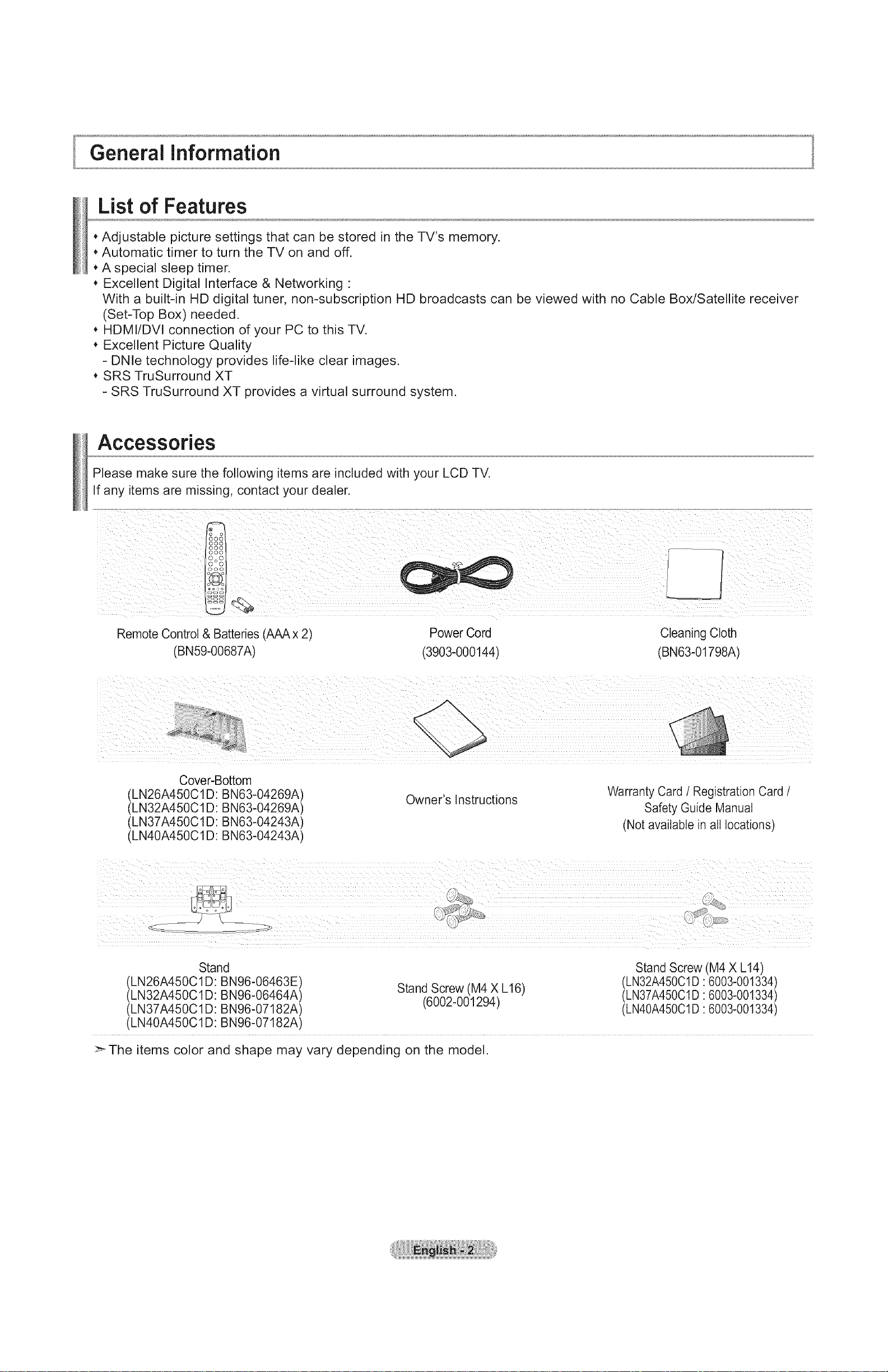
Please make sure the following items are included with your LCD TV.
If any items are missing, contact your dealer.
Remote Control & Batteries (AAA x 2'
(BN59-00687A)
Cover-Bottom
(LN26A450C1D: BN63-04269A)
(LN32A450C1D: BN63-04269A)
(LN37A450C1D: BN63-04243A)
(LN40A450C1D: BN63-04243A)
Power Cord
(3903-000144)
Owner's Instructions
Cleaning Cloth
(BNe3-01798A)
Warranty Card / Registration Card /
Safety Guide Manual
(Not available in all locations)
Stand Stand Screw (M4 X L14)
(LN26A450C1 D: BN96-06463E) Stand Screw (M4 X L16) (LN32A450C1D 6003-001334)
(LN32A450C1 D: BN96-06464A) (6002-001294) (LN37A450C1D 6003-001334)
(LN37A450C1 D: BN96-07182A) (LN40A45001D 6003-001334)
(LN40A450C1D: BN96-07182A)
>_The items color and shape may vary depending on the model.
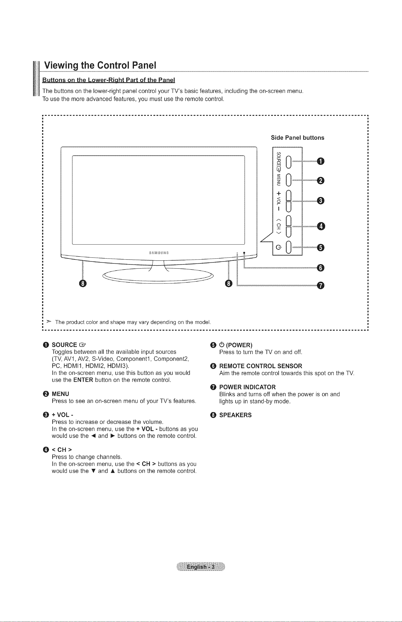
Viewing the Control Panel
Buttons on the Lower-RiLht Part of the Panel
The buttons on the lower-right panel control your TV's basic features, including the on-screen menu.
To use the more advanced features, you must use the remote control.
Side Panel buttons
>'- The product color and shape may vary depending on the model.
mIIIIIIIIIIIIIIIIIIIIIIIIIIIIIIIIIIIIIIIIIIIIIIIIIIIIIIIIIIIIIIIIIIIIIIIIIIIIIIIIIIIIIIIIIIIIIIIIIIIIIIIIi
O SOURCE C*_
Toggles between all the available input sources
(TV, AVl, AV2, S-Video, Component1, Component2,
PC, HDMI1, HDMI2, HDMI3).
In the on-screen menu, use this button as you would
use the ENTER button on the remote control.
O MENU
Press to see an on-screen menu of your TV's features.
O + VOL -
Press to increase or decrease the volume.
In the on-screen menu, use the + VOL - buttons as you
would use the 4 and _ buttons on the remote control.
O<CH>
Press to change channels.
In the on-screen menu, use the < CH > buttons as you
would use the _' and A buttons on the remote control.
@ (_ (POWER)
Press to turn the TV on and off.
O REMOTE CONTROL SENSOR
Aim the remote control towards this spot on the TV.
O POWER INDICATOR
Blinks and turns off when the power is on and
lights up in stand-by mode.
O SPEAKERS
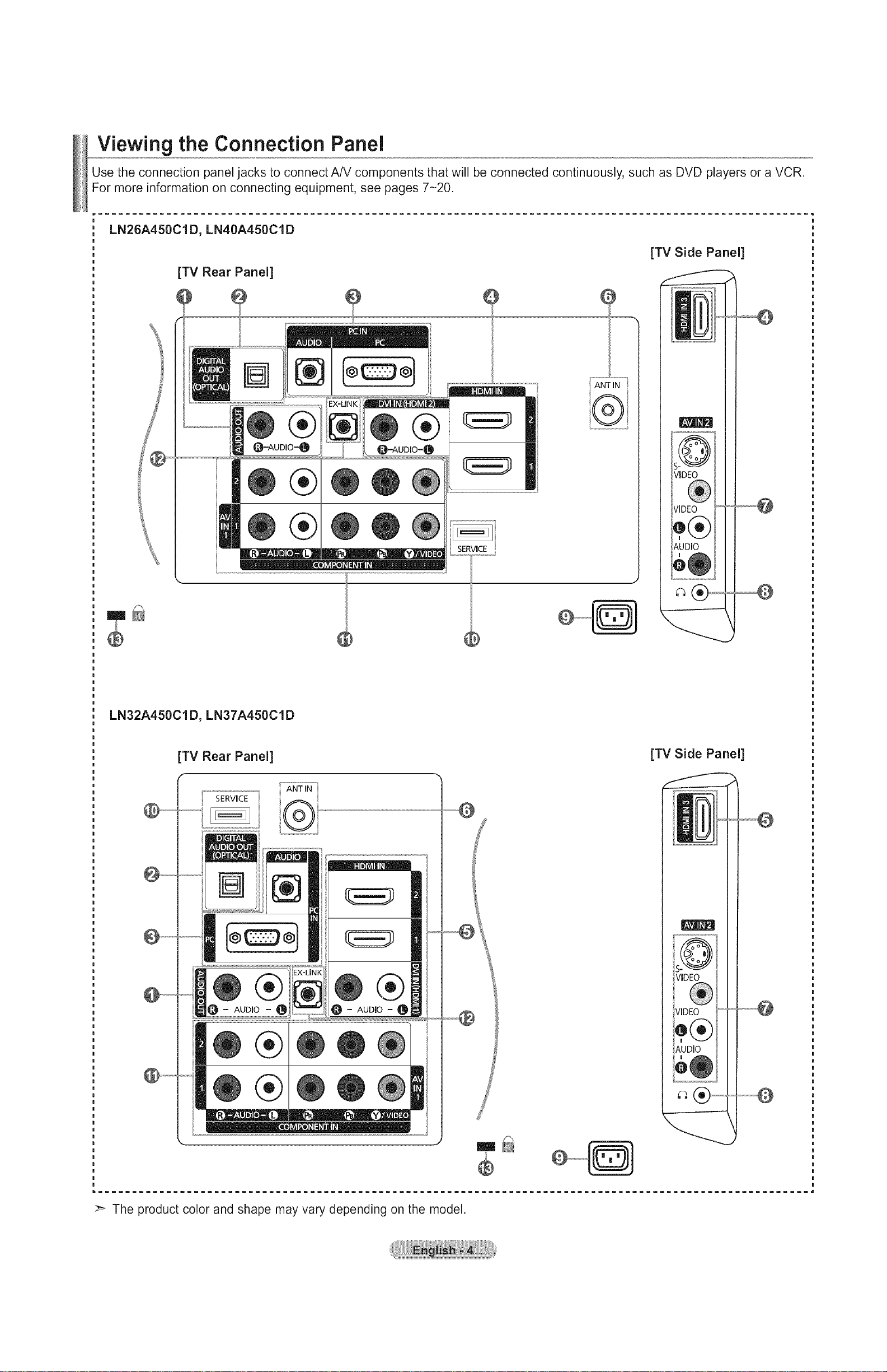
Viewing the Connection Panel
Use the connection panel jacks to connect A/V components that will be connected continuously, such as DVD players or a VCR.
For more information on connecting equipment, see pages 7-20.
LN26A450C1D, LN40A450C1D
[TV Side Panel]
[TV Rear Panel]
ANT mN
®
LN32A450C1D, LN37A450C1D
[TV Rear Panel]
SERVICE
ANT IN
SERVICE
VIDEO
VIDEO
Q(®
))1
AUDIO
em_
[TV Side Panel]
®
AUDIO
AUDIO
®
®
The product color and shape may vary depending on the model.
O AUDIO OUT
Connects to the audio input jacks on your Amplifier/Home theater.
O DIGITAL AUDIO OUT (OPTICAL)
Connects to a Digital Audio component.
O PC IN [PC]I[AUDIO]
Connects to the video and audio output jacks on your PC.
O HDMI IN 1, 2, 3/DVI IN(HDMI2)[R-AUDIO-L] (LN26A450C1D, LN40A450C1D)
Connects to the HDMI jack of a device with an HDMI output.
Use the HDMI IN 2 jack for DVl connection to an external device.
Use a DVl to HDMI cable or DVI-HDMI adapter (DVl to HDMI) for video connection and the
DVl IN (HDMI2) [R-AUDIO-L] jacks for audio.
- No sound connection is needed for an HDMI to HDMI connection.
- When using an HDMI/DVl cable connection, you must use the HDMI IN 2 jack.
O HDMI IN 1, 2, 3 / DVl IN(HDMIt)[R-AUDIO-L] (LN32A450C1D, LN37A450C1D)
Connects to the HDMI jack of a device with an HDMI output.
Use the HDMI IN 1 jack for DVl connection to an external device.
Use a DVl to HDMI cable or DVI-HDMI adapter (DVI to HDMI) for video connection and the
DVl IN (HDMI1) [R-AUDIO-L] jacks for audio.
- No sound connection is needed for an HDMI to HDMI connection.
- When using an HDMI/DVl cable connection, you must use the HDMI IN 1 jack.
O ANT IN
Connects to an antenna or cable TV system.
O AV IN 2
Video and audio inputs for external devices, such as a camcorder or VCR.
S-VIDEO
Connects an S-Video signal from a camcorder or VCR.
O _ (HEADPHONE)
Connects a set of external headphones for private listening.
Q POWER INPUT
Connects the supplied power cord.
_) SERVICE
Connector for SERVICE only.
(D COMPONENT IN 1, 2
The COMPONENT IN 1 jack is also used as the AV IN 1 jack.
- Connect the video cable to the COMPONENT IN 1 [Y/VIDEO] jack and the audio cable to the
COMPONENT IN 1 [R-AUDIO-L] jacks.
_i_ EX-LINK
- LN26A450C1D
Connector for SERVICE only.
- LN32A450CtD / LN37A450Cl D / LN40A450CtD
Connect this to the jack on the optional wall mount bracket. This will allow you to adjust the TV viewing angle using
your remote control.
_) KENSINGTON LOCK
The Kensington Lock (optional) is a device used to physically fix the system when used in a public place.
If you want to use a locking device, contact the dealer where you purchased the TV.
>_The location of the Kensington Lock may be different depending on its model.
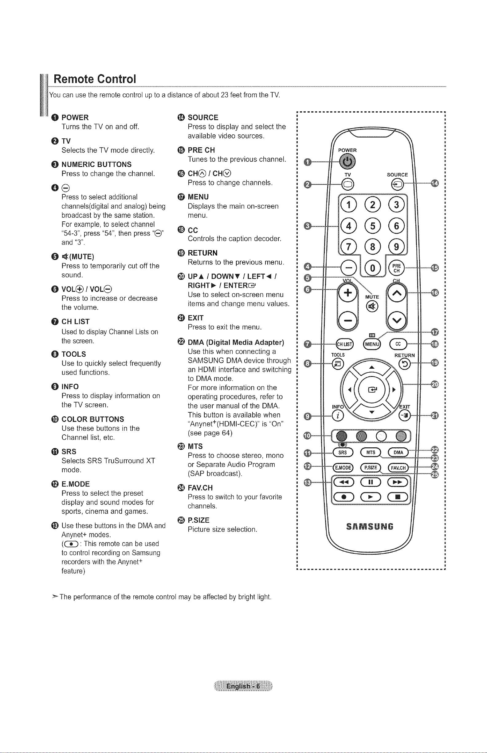
Remote Control
You can use the remote control up to a distance of about 23 feet from the TV.
O POWER
Turns the TV on and off.
O TV
Selects the TV mode directly.
O NUMERIC BUTTONS
Press to change the channel.
OG
Press to select additional (_l
channels(digital and analog) being
broadcast by the same station.
For example, to select channe!(_y
"54-3", press "54", then press
and "3".
O =_(MUTE)
Press to temporarily cut off the
sound.
e VOL@/VOLG
Press to increase or decrease
the volume.
O CH LiST
Used to display Channel Lists on
the screen.
O TOOLS
Use to quickly select frequently
used functions.
Q INFO
Press to display information on
the TV screen.
_) COLOR BUTTONS
Use these buttons in the
Channel list, etc.
(D SRS
Selects SRS TruSurround XT
mode.
E.MODE
Press to select the preset
display and sound modes for
sports, cinema and games.
_) Use these buttons in the DMA and
Anynet+ modes.
(_: This remote can be used
to control recording on Samsung
recorders with the Anynet ÷
feature)
SOURCE
@
Press to display and select the
available video sources.
PRE CH
Tunes to the previous channel.
@ CH(_) I CH(_
Press to change channels.
MENU
Displays the main on-screen
menu.
CC
Controls the caption decoder.
@
RETURN
Returns to the previous menu.
UPA / DOWNT / LEFT_ /
RIGHT_ / ENTER_
Use to select on-screen menu
items and change menu values.
EXIT
@
Press to exit the menu.
@
DMA (Digital Media Adapter)
Use this when connecting a
SAMSUNG DMA device through
an HDMI interface and switching
to DMA mode.
For more information on the
operating procedures, refer to
the user manual of the DMA.
This button is available when
"Anynet÷(HDMI-CEC) '' is "On"
(see page 64)
MTS
@
Press to choose stereo, mono
or Separate Audio Program
(SAP broadcast).
FAV.CH
Press to switch to your favorite
channels.
_) P.SIZE
Picture size selection.
TOOLS
INF
-C
®
@-
5
RETURN
>- The performance of the remote control may be affected by bright light.
installing Batteries in the Remote Control
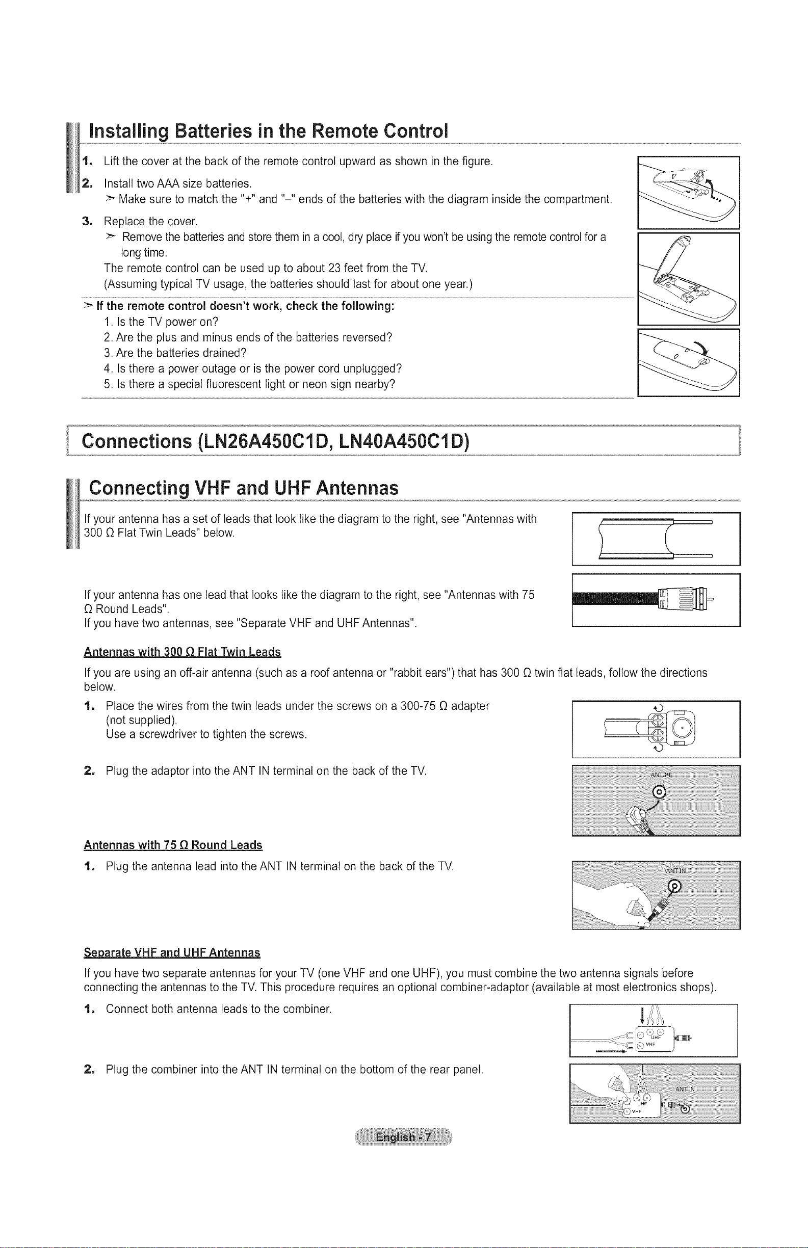
1, Lift the cover at the back of the remote control upward as shown in the figure.
2, Install two AAA size batteries.
Make sure to match the %" and "-" ends of the batteries with the diagram inside the compartment.
1
Replace the cover.
Remove the batteries and store them in a cool, dry place if you won't be using the remote control for a
long time.
The remote control can be used up to about 23 feet from the TV.
(Assuming typical TV usage, the batteries should last for about one year.)
:_ if the remote control doesn't work, check the following:
1. Is the TV power on?
2. Are the plus and minus ends of the batteries reversed?
3. Are the batteries drained?
4. Is there a power outage or is the power cord unplugged?
5. Is there a special fluorescent light or neon sign nearby?
I
Connections (LN26A450ClD, LN40A450ClD)
Connecting VHF and UHFAntennas
If your antenna has a set of leads that look like the diagram to the right, see "Antennas with
300 O Flat Twin Leads" below.
If your antenna has one lead that looks like the diagram to the right, see "Antennas with 75
O Round Leads".
If you have two antennas, see "Separate VHF and UHF Antennas".
Antennas with 300 _ Flat Twin Leads
If you are using an off-air antenna (such as a roof antenna or "rabbit ears") that has 300 O twin flat leads, follow the directions
below.
1
Place the wires from the twin leads under the screws on a 300-75 O adapter
(not supplied).
Use a screwdriver to tighten the screws.
2, Plug the adaptor into the ANT IN terminal on the back of the TV.
Antennas with 75 _ Round Leads
1, Plug the antenna lead into the ANT IN terminal on the back of the TV.
._.parate VHF and UHF Antennas
If you have two separate antennas for your TV (one VHF and one UHF), you must combine the two antenna signals before
connecting the antennas to the TV. This procedure requires an optional combiner-adaptor (available at most electronics shops).
1. Connect both antenna leads to the combiner. __tJ':"'
_J:=i
2, Plug the combiner into the ANT IN terminal on the bottom of the rear panel.

Connecting Cable TV
To connect to a cable TV system, follow the instructions below.
Cable without a Cable Box
1. Plug the incoming cable into the ANT IN terminal on the back of the TV.
:_ Because this TV iscable-ready, you do not needa cable box to view unscrambled cable channels.
Connecting to a Cable Box that Descrambles All Channels
1, Find the cable that is connected to the ANT OUT terminal on your cable box.
Thisterminal might be labeled"ANTOUT", "VHFOUT"or simply, "OUT".
2, Connect the other end of this cable to the ANT IN terminal on the back of the TV.
ii !i!iiiiii! i
_iiiiiiiiiiiiiiiiiiiiiiiiiiiiiiiiiiiiiiiiiiiiiiiiiiiiiiiiiiiiiiiiiiiiiiiiiiiiiiiiiiiiiiiiiiiiiiiiiiiiiiiiiiiiiiiiiiiiiiiiiiiiiiiiiiiiiiiiiiiiiiiiiiiiiiiiiiiiiiiiiiiiiiiiiiiiiiiiiiiiiiiiiiiiiiiiiiiiiiiiiiiiiiiiiiiiiiiiiiiiiiiiiiiiiiiiiiiiiiiiiiiiiiiiiiiiiiiiiii____
IZIN ANT OUT;j_
.... J _,'i,_i_ii_ii_ii__i,i_'_'_ __i
!!_!i¸_!_i_i_ii_ii_ii_ii_ii_ii_ii_ii_ii_ii_ii_ii_ii_ii_ii_ii_ii_ii_ii_ii_ii_ii_/i!i!i!i!i!i!i!i!i!i!i!i!i!i!i!i!i!i!i!i!i!i!i!i!i!i!i!i!i!i!i!i!i!i!i!i!i!i!i!i!i!i!i!i!i!i!i!i!i!i!i!i!i!i!i!i!i!i!i!i!i!i!i!i!i!i!i!i!i!i!i!i!i!i!i!i!i!i!i!i!i!i!i!i!i!i!i___
/ _:i:i!iii!ii!_i¸¸_¸¸¸¸i_!iiiiiiiiiiiiiiiiiiiiiiiiiiiiiiiiiiiiiiiiiiiiiiiiiiiiiiiiiiiiiiiiiiiiiiiiiiiiiiiiiiiiiii_
Connectinq to a Cable Box that Descrambles Some Channels
If your cable box descrambtes only some channels (such as premium channels), follow the instructions below. You wilt need a two-
way splitter, an RF (A/B) switch and four lengths of RF cable. (These items are available at most electronics stores.)
ll Find and disconnect the cable that is
connected to the ANT IN terminal on your
cable box.
This terminal might be labeled "ANT IN",
"VHF IN" or simply, "IN".
2, Connect this cable to a two-way splitter.
Incoming
cable
1 Connect an RF cable between the OUTPUT
terminal on the splitter and the IN terminal
on the cable box.
1 Connect an RF cable between the
ANT OUT terminal on the cable box and
the B-IN terminal on the RF(A/B) switch.
1
Connect another cable between the other
OUT terminal on the splitter and the A-IN
terminal on the RF (A/B) switch.
1
Connect the last RF cable between the
OUT terminal on the RF (A/B) switch and
the ANT IN terminal on the rear of the TV.
r
cable...... rSplitte_ _ !
Cable Box
_Cable Box_ Switch
Inco_g ........ S_ _Z c_ °L_ _B)
Cable Box Switch
__i_ _ _ ANT IN
Incoming k._ _ ........ _ __ TV Rear
cable .... Y I I
Splitter _ _ RF (A/El)
Cable Box Switch
After you have made this connection, set the A/B switch to the "A" position for normal viewing. Set the A/B switch to the "B" position to
view scrambled channels. (When you set the A/B switch to "B", you will need to tune your TV to the cable box's output channel, which is
usually channel 3 or 4.)
Connectinga DVDPlayer orCableBo×/Satellitereceiver(Set-TopBox)via HDIVll
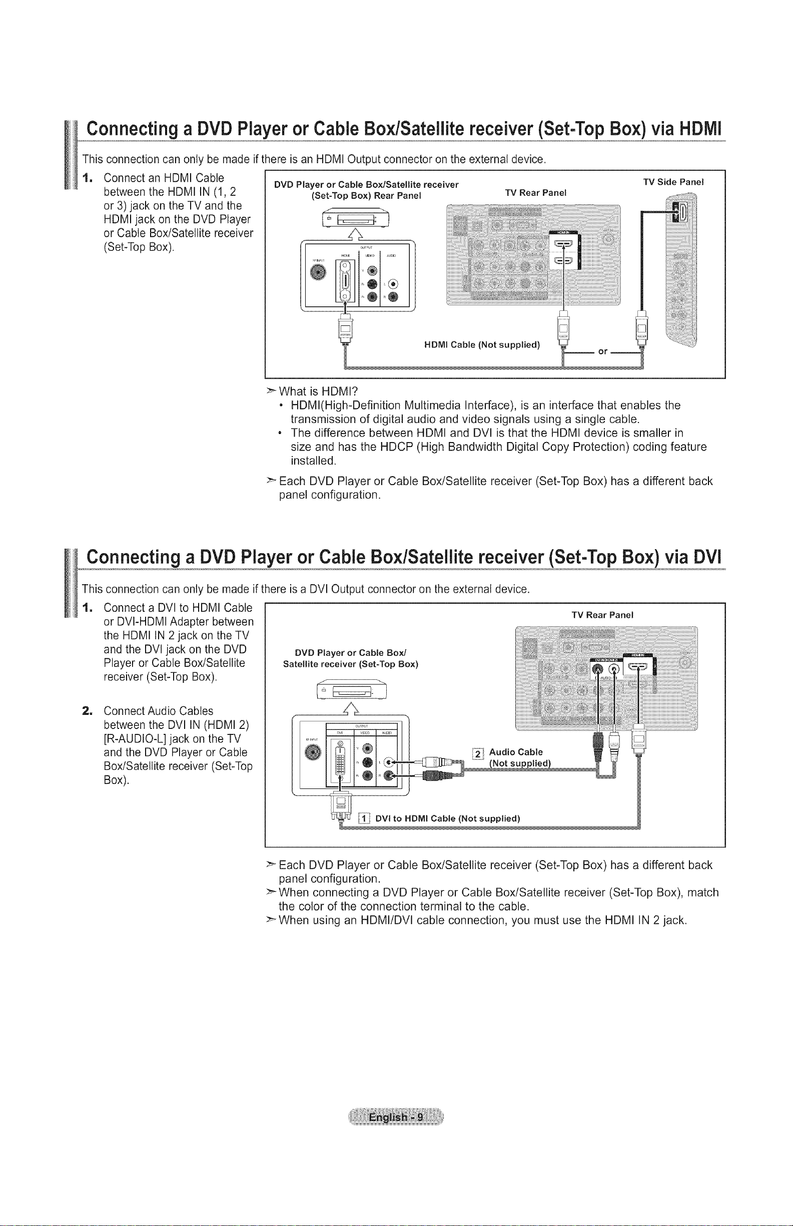
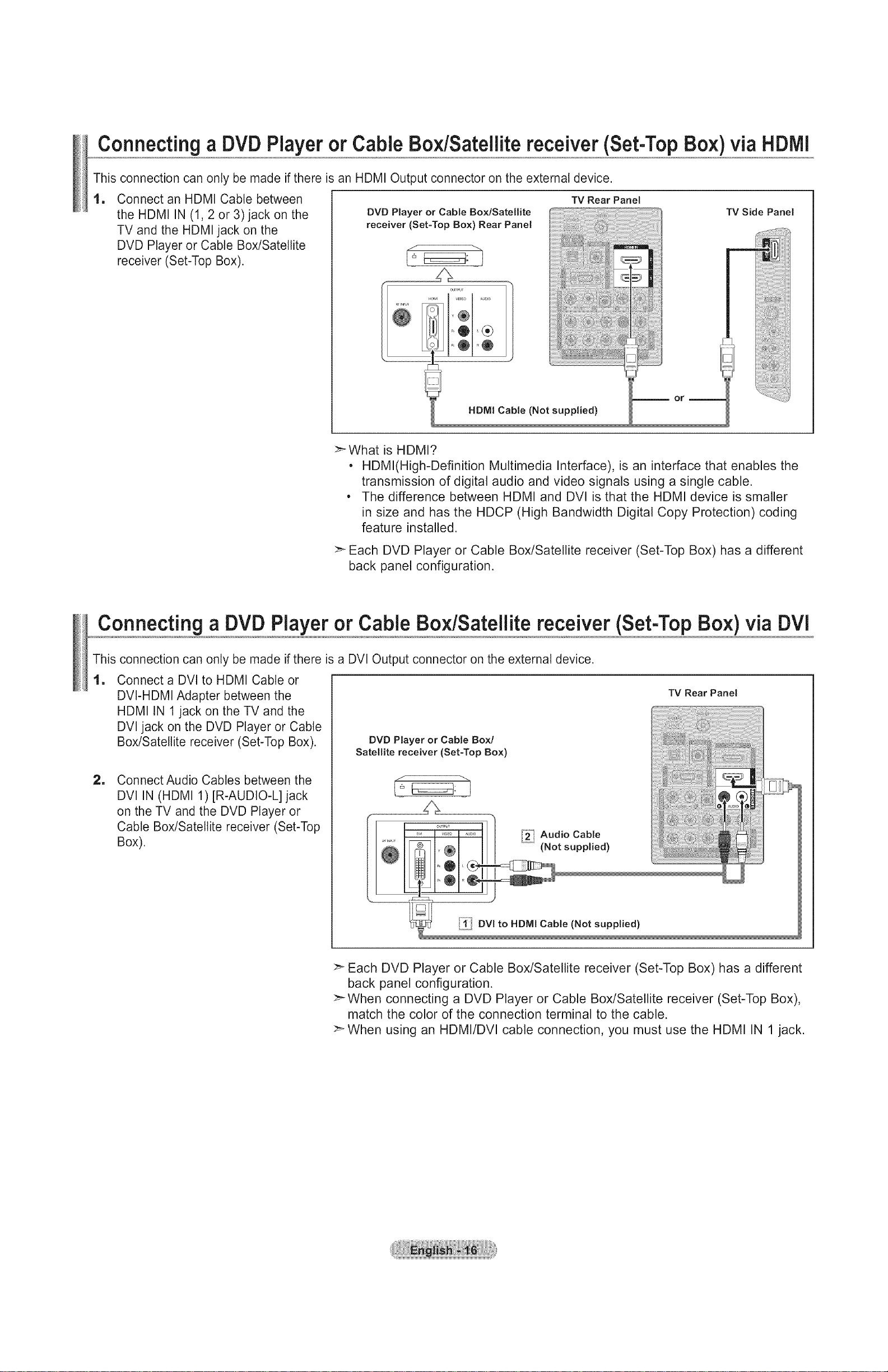
This connection can only be made if there is an HDMI Output connector on the external device.
1 Connect an HDMI Cable
between the HDMI IN (1,2
or 3) jack on the TV and the
HDMI jack on the DVD Player
or Cable Box/Satellite receiver
(Set-Top Box).
DVD Player or Cable Box/Satellite receiver
(Set-Top Box) Rear Panel
TV Rear Panel
>-What is HDMI?
• HDMl(High-Definition Multimedia Interface), is an interface that enables the
transmission of digital audio and video signals using a single cable.
• The difference between HDMI and DVl is that the HDMI device is smaller in
size and has the HDCP (High Bandwidth Digital Copy Protection) coding feature
installed.
TV Side Panel
Each DVD Player or Cable Box/Satellite receiver (Set-Top Box) has a different back
panel configuration.
Connecting a DVD Player or Cable Bo×/Sateilite receiver (Set-Top Box) via DVi
This connection can only be made if there is a DVl Output connector on the external device.
1
Connect a DVI to HDMI Cable
or DVI-HDMI Adapter between
the HDMI IN 2 jack on the TV
and the DVl jack on the DVD
Player or Cable Box/Satellite
receiver (Set-Top Box).
=
Connect Audio Cables
between the DVl IN (HDMI 2)
[R-AUDIO-L] jack on the TV
and the DVD Player or Cable
Box/Satellite receiver (Set-Top
Box).
DVD Player or Cable Box/
Satellite receiver (Set-Top Box)
÷
TV Rear Panel
>" Each DVD Player or Cable Box/Satellite receiver (Set-Top Box) has a different back
panel configuration.
When connecting a DVD Player or Cable Box/Satellite receiver (Set-Top Box), match
the color of the connection terminal to the cable.
_When using an HDMI/DVI cable connection, you must use the HDMI IN 2 jack.
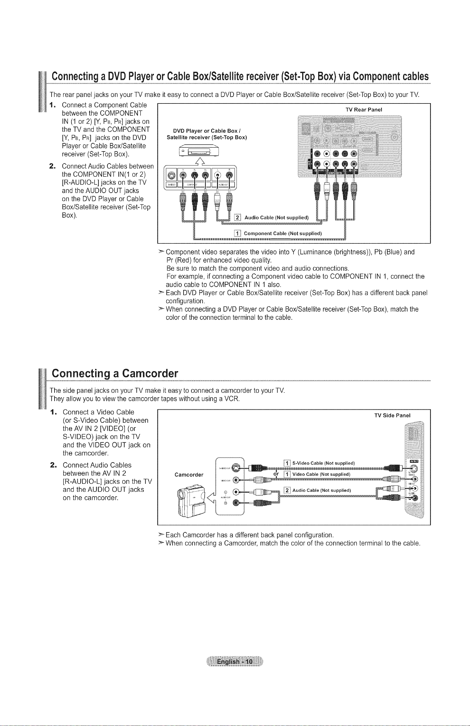
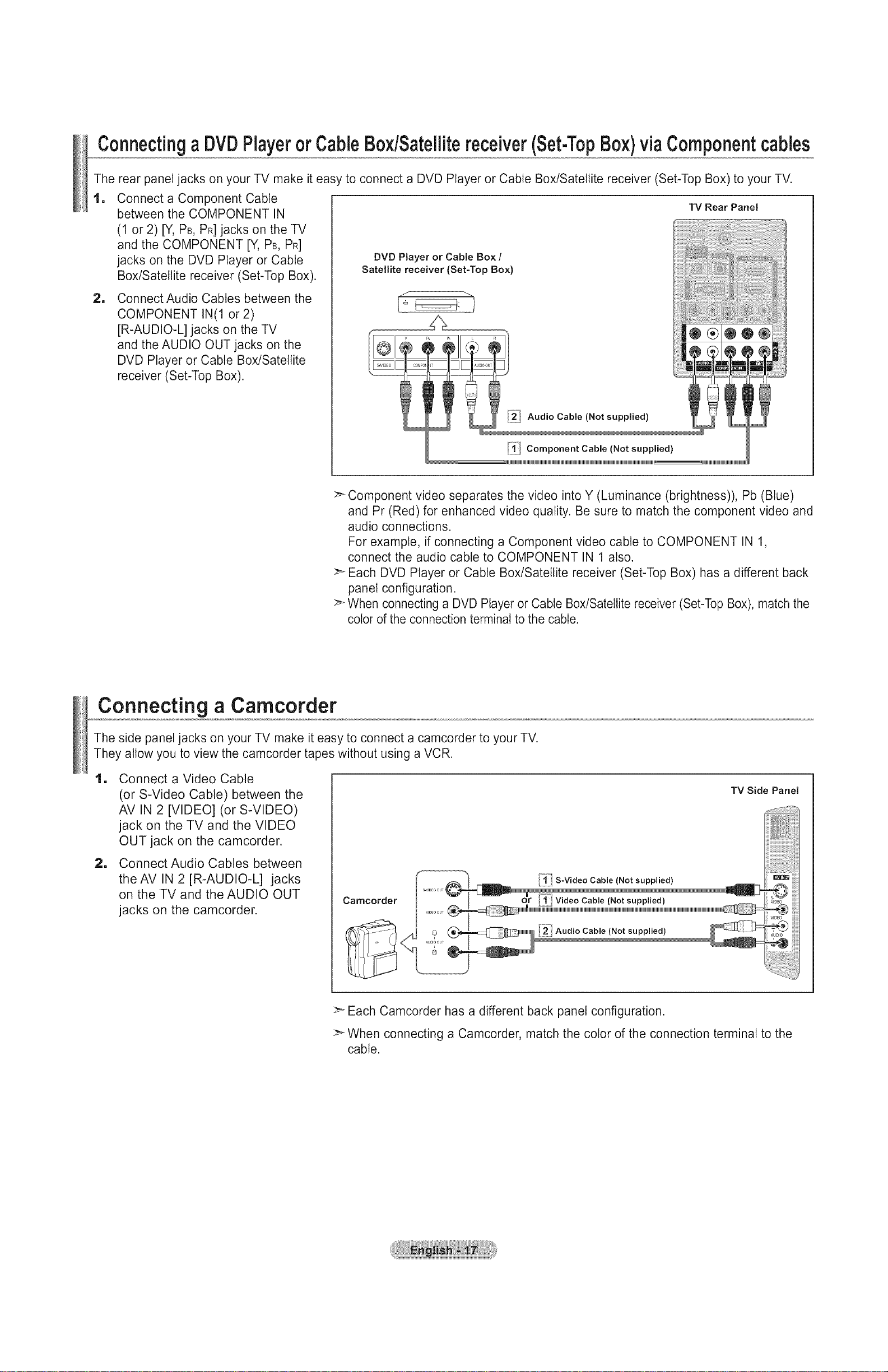
ConnectingaDVDPlayerorCableBox/Satellitereceiver(Set-TopBox)viaComponentcables
The rear panel jacks on your TV make it easy to connect a DVD Player or Cable Box/Satellite receiver (Set-Top Box) to your TV.
1
Connect a Component Cable
between the COMPONENT
IN (1 or 2) [Y, PB,PR]jacks on
the TV and the COMPONENT
[Y, PB, PR] jacks on the DVD
Player or Cable Box/Satellite
receiver (Set-Top Box).
1
Connect Audio Cables between
the COMPONENT IN(1 or 2)
[R-AUDIO-L] jacks on the TV
and the AUDIO OUT jacks
on the DVD Player or Cable
Box/Satellite receiver (Set-Top
Box).
DVD Player or Cable Box /
Satellite receiver (Set-Top Box)
J ""1
,, t
!11 i
TV Rear Panel
__M MMMMMMMMMMMMMMM
Component Cable (Not supplied)
:_ Component video separates the video into Y (Luminance (brightness)), Pb (Blue) and
Pr (Red) for enhanced video quality.
Be sure to match the component video and audio connections.
For example, if connecting a Component video cable to COMPONENT IN 1, connect the
audio cable to COMPONENT IN 1 also.
:_ Each DVD Player or Cable Box/Satellite receiver (Set-Top Box) has a different back panel
configuration.
>_When connecting a DVD Player or Cable Box/Satellite receiver (Set-Top Box), match the
color of the connection terminal to the cable.
Connecting a Camcorder
The side panel jacks on your TV make it easy to connect a camcorder to your TV.
They allow you to view the camcorder tapes without using a VCR.
lm
Connect a Video Cable
(or S-Video Cable) between
the AV IN 2 [VIDEO] (or
S-VIDEO) jack on the TV
and the VIDEO OUT jack on
the camcorder.
m
Connect Audio Cables
between the AV IN 2
[R-AUDIO-L] jacks on the TV
and the AUDIO OUT jacks
on the camcorder.
TV Side Panel
Camcorder
S-VtD_,_OUT
VID _3OUT _ "_lml
.........S-Video Cable (Not supplied)
or
"_1! Video Cable (Not supplied)
_ Audio Cable (Not supplied)
>_Each Camcorder has a different back panel configuration.
>" When connecting a Camcorder, match the color of the connection terminal to the cable.
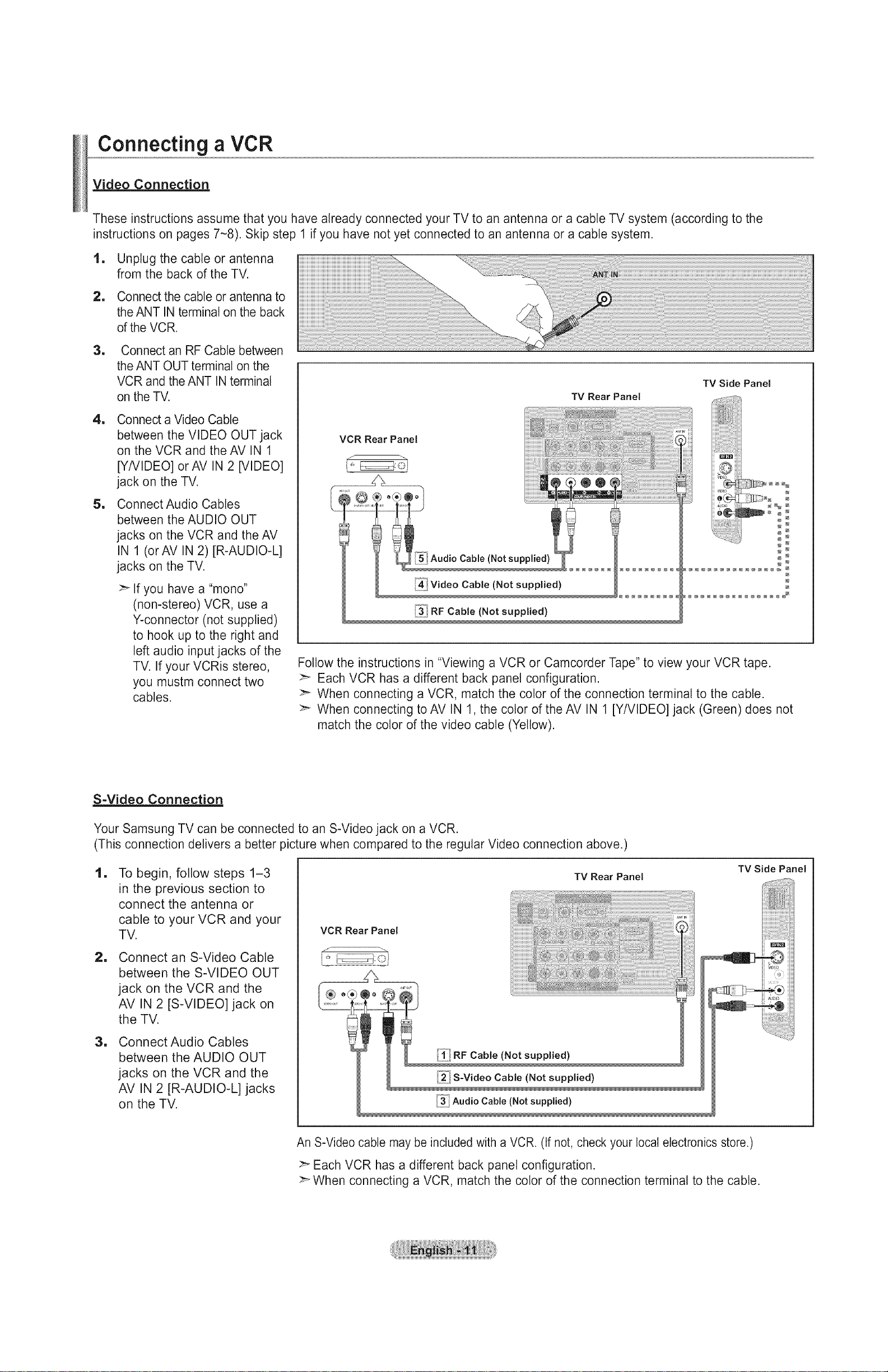
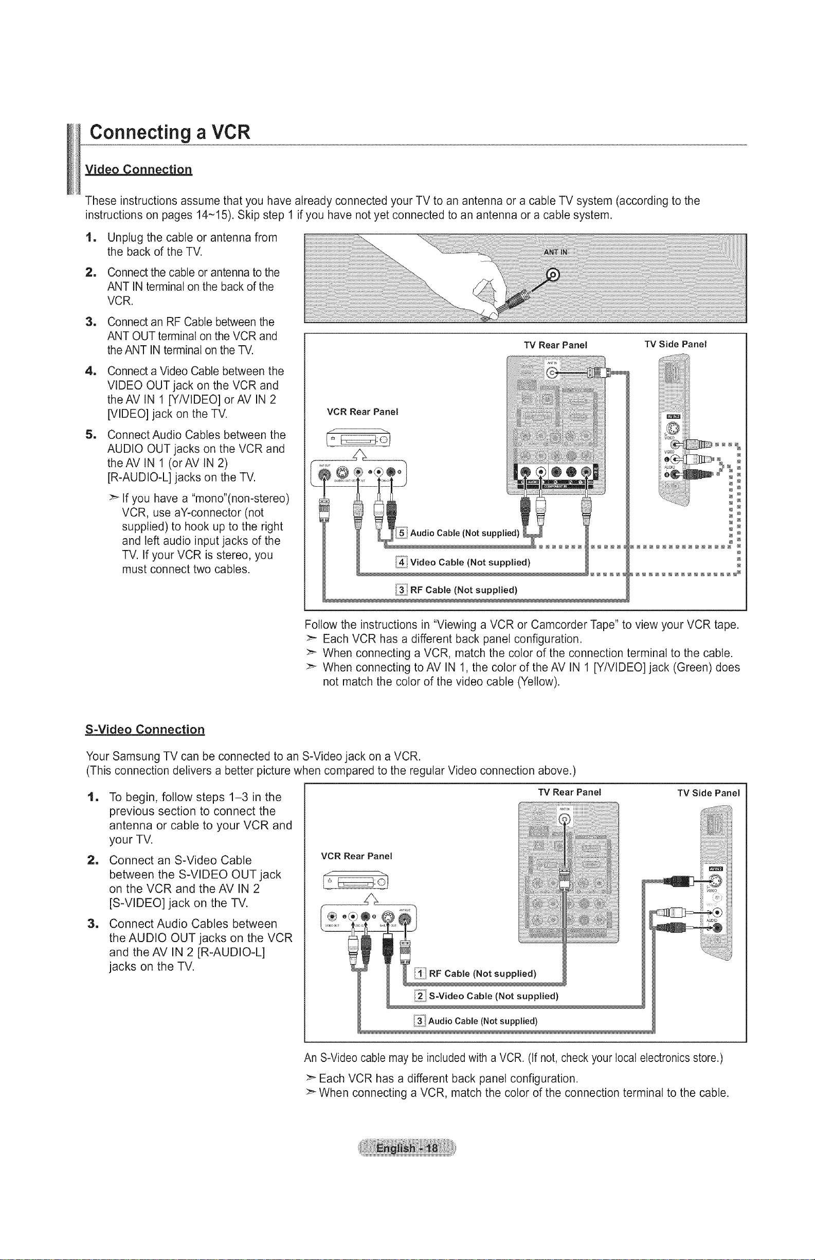
Connecting a VCR
Video Connection
These instructions assume that you have already connected your TV to an antenna or a cable TV system (according to the
instructions on pages 7-8). Skip step 1 if you have not yet connected to an antenna or a cable system.
1, Unplug the cable or antenna
from the back of the TV.
2, Connect the cable or antenna to
the ANT IN terminal on the back
of the VCR.
1
Connect an RF Cable between
the ANT OUT terminal on the
VCR and the ANT IN terminal
on the TV.
1
Connect a Video Cable
between the VIDEO OUT jack
on the VCR and the AV IN 1
[YNIDEO] orAV IN 2 [VIDEO]
jack on the TV.
1
Connect Audio Cables
between the AUDIO OUT
jacks on the VCR and the AV
IN 1 (orAV IN 2)[R-AUDIO-L]
jacks on the TV.
TV Rear Panel
VCR Rear Panel
f
TV Side Panel
_ o°°
_ N
_ N
_ N
_ N
N _
o
>- If you have a "mono"
(non-stereo) VCR, use a
Y-connector (not supplied)
to hook up to the right and
left audio input jacks of the
TV. If your VCRis stereo,
you mustm connect two
cables.
Follow the instructions in "Viewing a VCR or Camcorder Tape" to view your VCR tape.
:_ Each VCR has a different back panel configuration.
>_ When connecting a VCR, match the color of the connection terminal to the cable.
>_ When connecting to AV IN 1, the color of the AV IN 1 [Y/VIDEO] jack (Green) does not
match the color of the video cable (Yellow).
S-Video Connection
Your Samsung TV can be connected to an S-Video jack on a VCR.
(This connection delivers a better picture when compared to the regular Video connection above.)
1
To begin, follow steps 1-3
TV Rear Panel
in the previous section to
connect the antenna or
cable to your VCR and your
TV.
VCR Rear Panel
TV Side Panel
1
Connect an S-Video Cable
between the S-VIDEO OUT
jack on the VCR and the
AV IN 2 [S-VIDEO] jack on
the TV.
1
Connect Audio Cables
between the AUDIO OUT
jacks on the VCR and the
AV IN 2 [R-AUDIO-L] jacks
on the TV.
_ RF Cable (Not supplied)
.2. S=Video Cable (Not supplied)
Audio Cable (Not supplied)
An S-Video cable may be included with a VCR. (If not, check your local electronics store.)
:_ Each VCR has a different back panel configuration.
>_When connecting a VCR, match the color of the connection terminal to the cable.
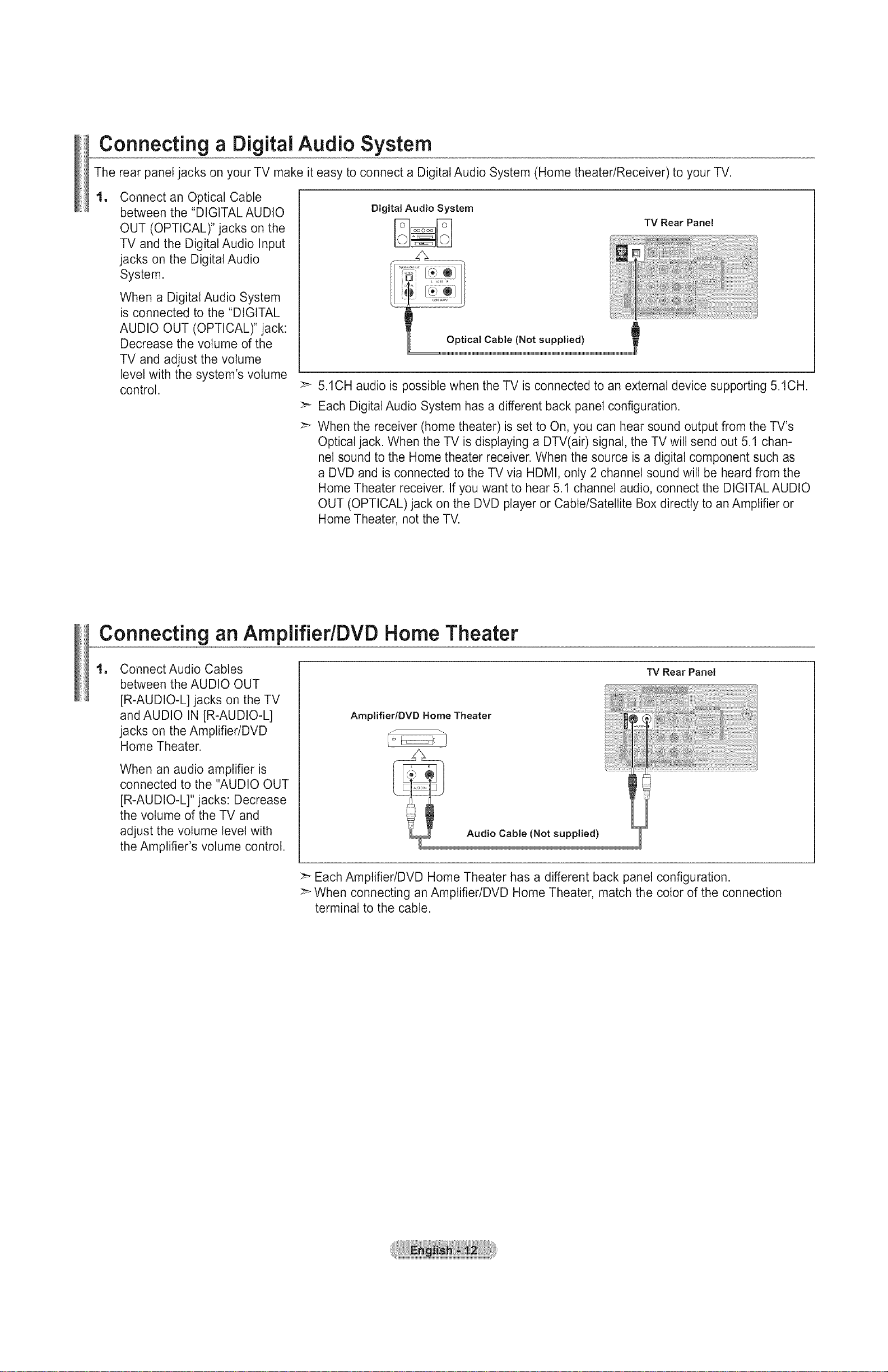
Connecting a DigitalAudio System
The rear panel jacks on your TV make it easy to connect a Digital Audio System (Home theater/Receiver) to your TV.
1
Connect an Optical Cable
between the "DIGITAL AUDIO
OUT (OPTICAL)" jacks on the
TV and the Digital Audio Input
jacks on the Digital Audio
System.
When a Digital Audio System
is connected to the "DIGITAL
AUDIO OUT (OPTICAL)" jack:
Decrease the volume of the
TV and adjust the volume
level with the system's volume
control.
5.1CH audio is possible when the TV is connected to an external device supporting 5.1CH.
Each Digital Audio System has a different back panel configuration.
When the receiver (home theater) is set to On, you can hear sound output from the TV's
Optical jack. When the TV is displaying a DTV(air) signal, the TV will send out 5.1 chan-
nel sound to the Home theater receiver. When the source is a digital component such as
a DVD and is connected to the TV via HDMI, only 2 channel sound will be heard from the
Home Theater receiver. If you want to hear 5.1 channel audio, connect the DIGITAL AUDIO
OUT (OPTICAL) jack on the DVD player or Cable/Satellite Box directly to an Amplifier or
Home Theater, not the TV.
Digital Audio System
TV Rear Panel
Optical Cable (Not supplied)
Connecting an AmplifiedDVD Home Theater
1 Connect Audio Cables
between the AUDIO OUT
[R-AUDIO-L] jacks on the TV
and AUDIO IN [R-AUDIO-L]
jacks on the Amplifier/DVD
Home Theater.
When an audio amplifier is
connected to the "AUDIO OUT
[R-AUDIO-L]" jacks: Decrease
the volume of the TV and
adjust the volume level with
the Amplifier's volume control.
Each Amplifier/DVD Home Theater has a different back panel configuration.
>- When connecting an Amplifier/DVD Home Theater, match the color of the connection
terminal to the cable.
Amplifier/DVD Home Theater
Audio Cable (Not supplied)
TV Rear Panel
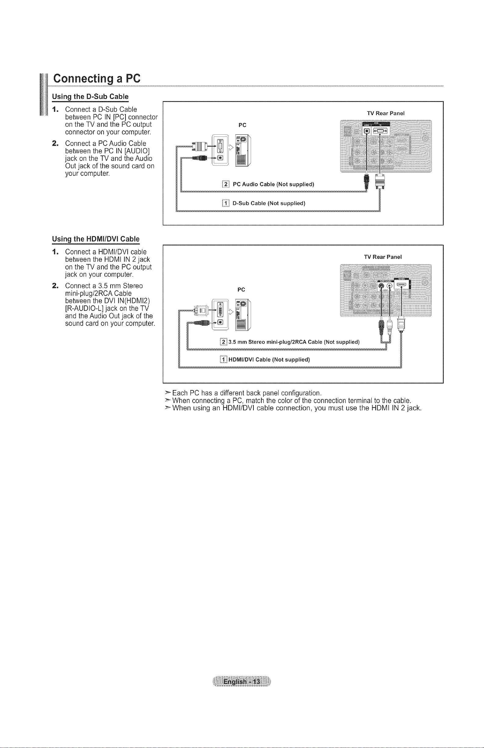
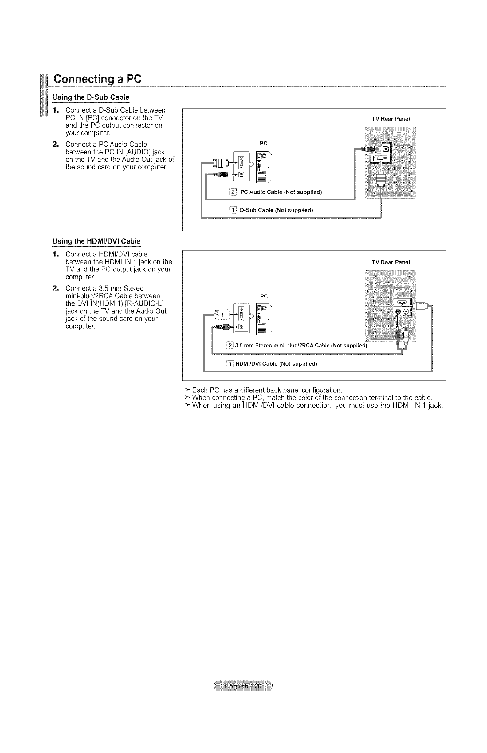
Connecting a PC
Using the D-Sub Cable
1
Connect a D-Sub Cable
between PC IN [PC] connector
on the TV and the PC output
connector on your computer.
=
Connect a PC Audio Cable
between the PC IN [AUDIO]
jack on the TV and the Audio
Out jack of the sound card on
your computer.
Using the HDMI/DVI Cable
1
Connect a HDMI/DVI cable
between the HDMI IN 2 jack
on the TV and the PC output
jack on your computer.
=
Connect a 3.5 mm Stereo
mini-plug/2RCA Cable
between the DVl IN(HDMI2)
[R-AUDIO-L] jack on the TV
and the Audio Out jack of the
sound card on your computer.
"iV Rear Panel
PC
TV Rear Panel
PC
i_! 3.5 mm Stereo mini-plugl2RCA Cable (Not supplied)
_ii HDMIIDVl Cable (Not supplied)
>" Each PC has a different back panel configuration.
>" When connecting a PC, match the color of the connection terminal to the cable.
>-When using an HDMI/DVI cable connection, you must use the HDMI IN 2 jack.
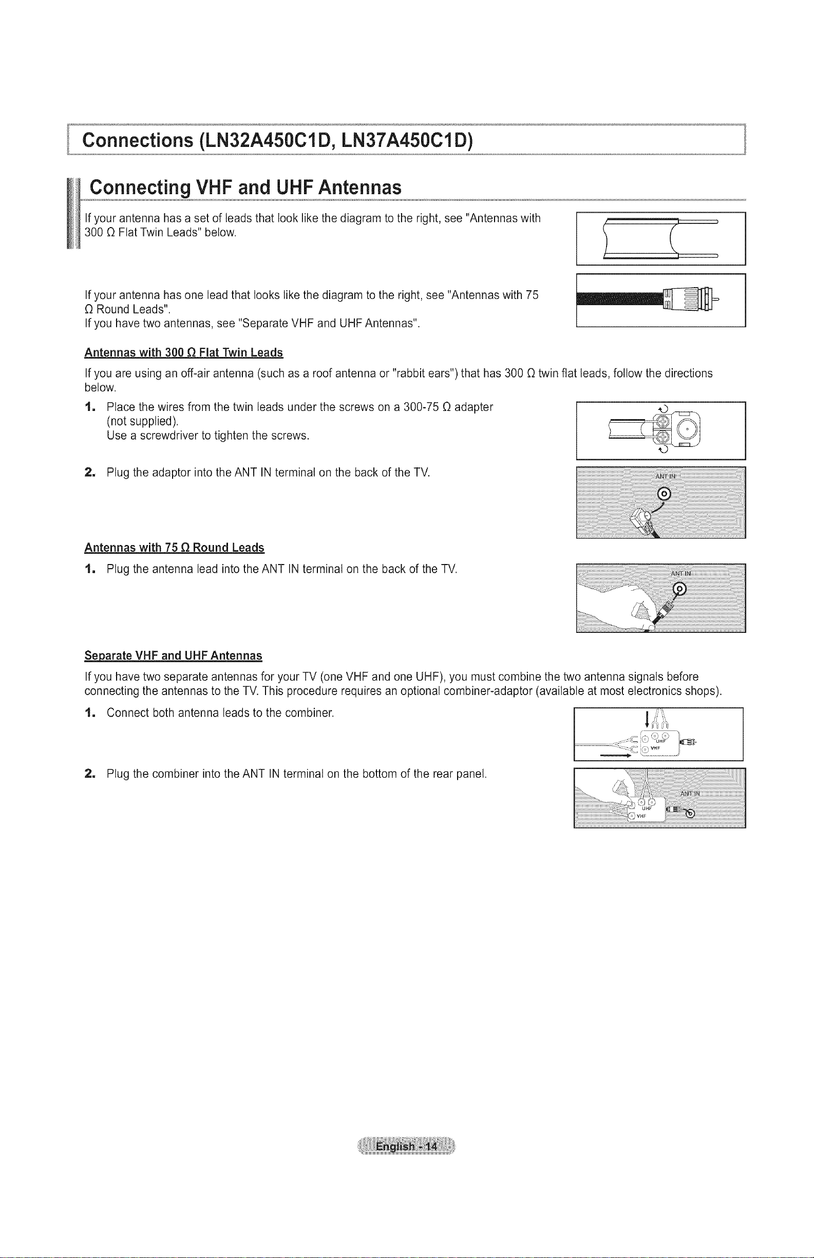
Connections (LN32A450Cl D, LN37A450Cl D)
Connecting VHF and UHFAntennas
If your antenna has a set of leads that look like the diagram to the right, see "Antennas with
300 O Flat Twin Leads" below.
If your antenna has one lead that looks like the diagram to the right, see "Antennas with 75
O Round Leads".
If you have two antennas, see "Separate VHF and UHF Antennas".
Antennas with 300 _ Fiat Twin Leads
If you are using an off-air antenna (such as a roof antenna or "rabbit ears") that has 300 O twin flat leads, follow the directions
below.
1
Place the wires from the twin leads under the screws on a 300-75 O adapter
(not supplied).
Use a screwdriver to tighten the screws.
2, Plug the adaptor into the ANT IN terminal on the back of the TV.
Antennas with 75 _ Round Leads
1, Plug the antenna lead into the ANT IN terminal on the back of the TV.
Se_parate VHF and UHF Antennas
Ifyou have two separate antennas for your TV (one VHF and one UHF), you must combine the two antenna signals before
connecting the antennas to the TV. This procedure requires an optional combiner-adaptor (available at most electronics shops).
! ,// 'i',
1 Connect both antenna leads to the combiner.
2, Plug the combiner into the ANT IN terminal on the bottom of the rear panel.
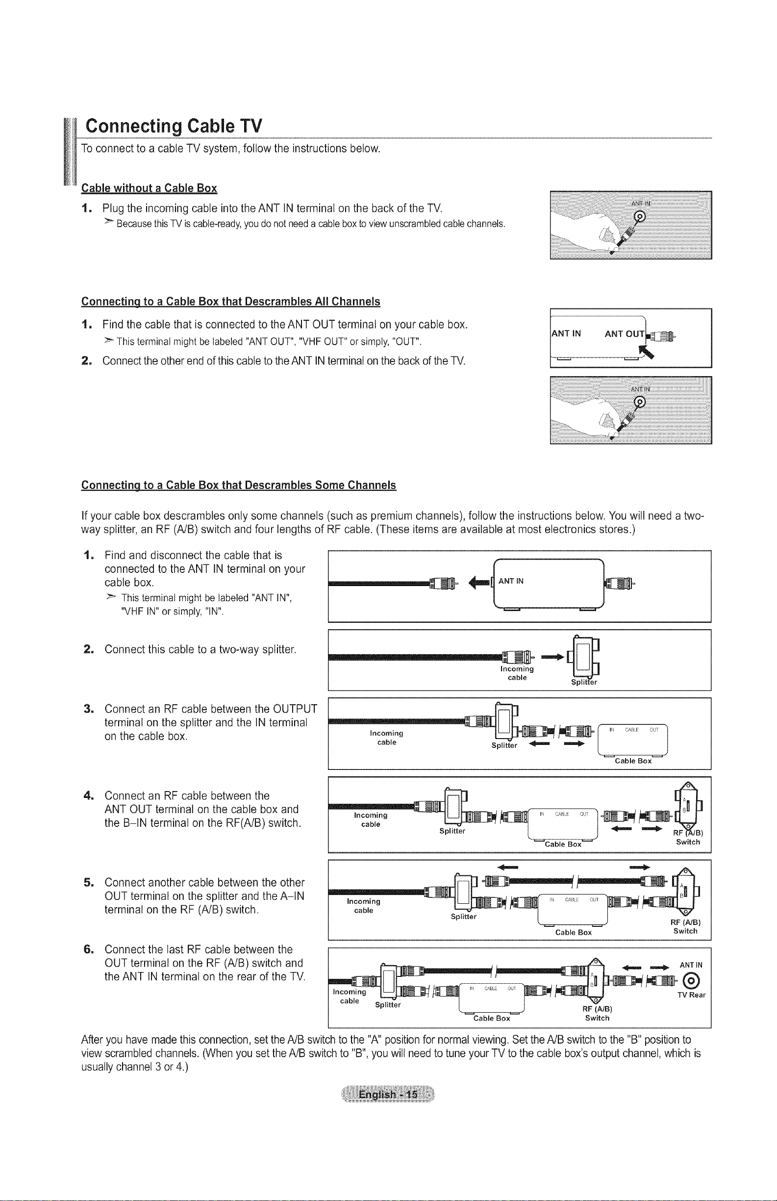
Connecting Cable TV
To connect to a cable TV system, follow the instructions below.
Cable without a Cable Box
1, Plug the incoming cable into the ANT IN terminal on the back of the TV.
:_ Because this TV iscable-ready, you do not needa cable box to view unscrambled cable channels.
Connecting to a Cable Box that Descrambles All Channels
1, Find the cable that is connected to theANT OUT terminal on your cable box.
_" Thisterminal might be labeled"ANTOUT", "VHFOUT"or simply, "OUT".
2, Connect the other end of this cable to the ANT IN terminal on the back of the TV.
NTIN ANT OUT_:_- _
_i_i!i! ;!!i!!!i;!!!!_:!ii!iiiiiiiil;;;;;;;;;;;;;;;;;:!_i !!!!!!!!!!!!!!!!!!!!!!!!!!!!!!!!!!!!!!!!!!!!!!!!!!!!!!!!!!!!!!!!!!!!!!!i!i!i!i¸
Connectinq to a Cable Box that Descrambles Some Channels
If your cable box descrambtes only some channels (such as premium channels), follow the instructions below. You wilt need a two-
way splitter, an RF (A/B) switch and four lengths of RF cable. (These items are available at most electronics stores.)
1 Find and disconnect the cable that is
connected to the ANT IN terminal on your
cable box.
This terminal might be labeled "ANT IN",
"VHF IN" or simply, "IN".
2, Connect this cable to a two-way splitter.
Incoming
cable
1 Connect an RF cable between the OUTPUT
terminal on the splitter and the IN terminal
on the cable box.
"_______ _I ,N oA0,.Eout
cable...... rSplitte_
Cable Box
1 Connect an RF cable between the
ANT OUT terminal on the cable box and
the B-IN terminal on the RF(A/B) switch.
_Cable Box_ Switch
1
Connect another cable between the other
OUT terminal on the splitter and the A-IN
terminal on the RF (A/B) switch.
1
Connect the last RF cable between the
OUT terminal on the RF (A/B) switch and
incoming _ _[_ ,N CAI_ 0,_, "_
• k ) RF (NB)
Cable Box Switch
ANT IN
the ANT IN terminal on the rear of the TV.
_,_ TV Rear
cable Splitter _ RF (Nt _ B)
Cable Box Switch
After you have made this connection, set the A/B switch to the "A" position for normal viewing. Set the A/B switch to the "B" position to
view scrambled channels. (When you set the A/B switch to "B", you will need to tune your TV to the cable box's output channel, which is
usually channel 3 or 4.)
Connectinga DVDPlayerorCableBox/Satellitereceiver(Set-TopBox)via HDMI
This connection can only be made if there is an HDMI Output connector on the external device.
1 Connect an HDMI Cable between
the HDMI IN (1, 2 or 3) jack on the
TV and the HDMI jack on the
DVD Player or Cable Box/Satellite
receiver (Set-Top Box).
DVD Player or Cable Box/Satellite
receiver (Set-Top Box) Rear Panel
_-What is HDMI?
• HDMl(High-Definition Multimedia Interface), is an interface that enables the
transmission of digital audio and video signals using a single cable.
• The difference between HDMI and DVl is that the HDMI device is smaller
in size and has the HDCP (High Bandwidth Digital Copy Protection) coding
feature installed.
TV Rear Panel
"IV Side Panel
or
Each DVD Player or Cable Box/Satellite receiver (Set-Top Box) has a different
back panel configuration.
Connecting a DVD Player or Cable Bo×/Satellite receiver (Set-Top Box) via DVi
This connection can only be made if there is a DVl Output connector on the external device.
1 Connect a DVI to HDMI Cable or
DVI-HDMI Adapter between the
HDMI IN 1 jack on the TV and the
DVl jack on the DVD Player or Cable
Box/Satellite receiver (Set-Top Box).
1 Connect Audio Cables between the
DVl IN (HDMI 1) [R-AUDIO-L] jack
on the TV and the DVD Player or
Cable Box/Satellite receiver (Set-Top
Box).
DVD Player or Cable Box/
Satellite receiver (Set-Top Box)
,2_ Audio Cable
(Not supplied)
TV Rear Panel
,,1/ DVl to HDMI Cable (Not supplied)
Each DVD Player or Cable Box/Satellite receiver (Set-Top Box) has a different
back panel configuration.
:_ When connecting a DVD Player or Cable Box/Satellite receiver (Set-Top Box),
match the color of the connection terminal to the cable.
_When using an HDMI/DVI cable connection, you must use the HDMI IN 1 jack.
ConnectingaDVOPlayerorCableBoxlSatellitereceiver(Set-TopBox)viaComponentcables
The rear panel jacks on your TV make it easy to connect a DVD Player or Cable Box/Satellite receiver (Set-Top Box) to your TV.
1
Connect a Component Cable
between the COMPONENT IN
(1 or 2) [Y, PB, PR]jacks on the TV
and the COMPONENT [Y, PB, PR]
jacks on the DVD Player or Cable
Box/Satellite receiver (Set-Top Box).
1
Connect Audio Cables between the
COMPONENT IN(1 or 2)
[R-AUDIO-L] jacks on the TV
and the AUDIO OUT jacks on the
DVD Player or Cable Box/Satellite
receiver (Set-Top Box).
DVD Player or Cable Box /
Satellite receiver (Set-Top Box)
2 Audio Cable (Not supplied)
iiii_i Component Cable (Not supplied)
IglglglglglglglglglglglglglglglglglglglglglglglglgMMMMMMMMMMMMMMMMMMMMMMMI IIIIIIIIIIIIIIIIIIIIIIIIIIIIIIIIIIIIIIIIIIIIIIIIIIIIIIIIIIIIIIIIIIIIIIIIIIII_lglglglglglglglglglglglglglglglglglglglglgl
TV Rear Panel
>_Component video separates the video into Y (Luminance (brightness)), Pb (Blue)
and Pr (Red) for enhanced video quality. Be sure to match the component video and
audio connections.
For example, if connecting a Component video cable to COMPONENT IN 1,
connect the audio cable to COMPONENT IN 1 also.
:_ Each DVD Player or Cable Box/Satellite receiver (Set-Top Box) has a different back
panel configuration.
>_When connecting a DVD Player or Cable Box/Satellite receiver (Set-Top Box), match the
color of the connection terminal to the cable.
Connecting a Camcorder
The side panel jacks on your TV make it easy to connect a camcorder to your TV.
They allow you to view the camcorder tapes without using a VCR.
1. Connect a Video Cable
(or S-Video Cable) between the
AV IN 2 [VIDEO] (or S-VIDEO)
jack on the TV and the VIDEO
OUT jack on the camcorder.
TV Side Panel
2, Connect Audio Cables between
the AV IN 2 [R-AUDIO-L] jacks
on the TV and the AUDIO OUT
jacks on the camcorder.
"_;li_"S-Video Cable (Not supplied)
Camcorder
?
or ,t/Video Cable (Not supplied)
2 Audio Cable (Not supplied)
>_Each Camcorder has a different back panel configuration.
:_ When connecting a Camcorder, match the color of the connection terminal to the
cable.
Connecting a VCR
Video Connection
These instructions assume that you have already connected your TV to an antenna or a cable TV system (according to the
instructions on pages 14-15). Skip step 1 if you have not yet connected to an antenna or a cable system.
1, Unplug the cable or antenna from
the back of the TV.
2, Connect the cable or antenna to the
ANT IN terminal on the back of the
VCR.
1
Connect an RF Cable between the
ANT OUT terminal on the VCR and
the ANT IN terminal on the TV.
1
Connect a Video Cable between the
VIDEO OUT jack on the VCR and
theAV IN 1 [YNIDEO] orAV IN 2
[VIDEO] jack on the TV.
1
Connect Audio Cables between the
AUDIO OUT jacks on the VCR and
theAV IN 1 (orAV IN 2)
[R-AUDIO-L] jacks on the TV.
TV Rear Panel
VCR Rear Panel
©
TV Side, Panel
>_ If you have a "mono"(non-stereo)
VCR, use aY-connector (not
supplied) to hook up to the right
5.._Audio Cable (Not supplied)
and left audio input jacks of the
TV. If your VCR is stereo, you
must connect two cables.
,4_ Video Cable (Not supplied)
.3_ RF Cable (Not supplied)
Follow the instructions in "Viewing a VCR or Camcorder Tape" to view your VCR tape.
Each VCR has a different back panel configuration.
>_ When connecting a VCR, match the color of the connection terminal to the cable.
:_ When connecting to AV IN 1, the color of the AV IN 1 [Y/VIDEO] jack (Green) does
not match the color of the video cable (Yellow).
S-Video Connection
Your Samsung TV can be connected to an S-Video jack on a VCR.
(This connection delivers a better picture when compared to the regular Video connection above.)
1. To begin, follow steps 1-3 in the
TV Rear Panel
previous section to connect the
antenna or cable to your VCR and
your TV.
2, Connect an S-Video Cable
VCR Rear Panel
between the S-VIDEO OUT jack
on the VCR and the AV IN 2
[S-VIDEO] jack on the TV.
TV Side Panel
3. Connect Audio Cables between
the AUDIO OUT jacks on the VCR
and theAV IN 2 [R-AUDIO-L]
jacks on the TV.
[_! RF Cable (Not supplied)
_ S-Video Cable (Not supplied
Audio Cable (Not supplied)
An S-Video cable may be included with a VCR. (If not, check your local electronics store.)
>_Each VCR has a different back panel configuration.
When connecting a VCR, match the color of the connection terminal to the cable.

Connecting a DigitalAudio System
The rear panel jacks on your TV make it easy to connect a Digital Audio System (Home theater/Receiver) to your TV.
1
Connect an Optical Cable between
the "DIGITAL AUDIO OUT
(OPTICAL)" jacks on the TV and
the Digital Audio Input jacks on the
Digital Audio System.
When a Digital Audio System is
connected to the "DIGITAL AUDIO
OUT (OPTICAL)" jack: Decrease
the volume of the TV and adjust
the volume level with the system's
volume control.
Digital Audio System
Optical Cable (Not supplied)
>_ 5.1CH audio is possible when the TV is connected to an external device supporting
5.1CH.
>_ Each Digital Audio System has a different back panel configuration.
TV Rear Panel
>_ When the receiver (home theater) is set to On, you can hear sound output from
the TV's Optical jack. When the TV is displaying a DTV(air) signal, the TV will send
out 5.1 channel sound to the Home theater receiver. When the source is a digital
component such as a DVD and is connected to the TV via HDMI, only 2 channel
sound wilt be heard from the Home Theater receiver. If you want to hear 5.1 channel
audio, connect the DIGITAL AUDIO OUT (OPTICAL)jack on the DVD player or
Cable/Satellite Box directly to an Amplifier or Home Theater, not the TV.
Connecting an AmplifiedDVD Home Theater
1. Connect Audio Cables between the
AUDIO OUT [R-AUDIO-L] jacks on
the TV and AUDIO IN [R-AUDIO-L]
jacks on the Amplifier/DVD Home
Theater.
When an audio amplifier is
connected to the "AUDIO OUT
[R-AUDIO-L]" jacks: Decrease the
volume of the TV and adjust the
volume level with the Amplifier's
volume control.
Amplifier/DVD Home Theater
Audio Cable (Not supplied)
TV Rear Panel
:_ Each Amplifier/DVD Home Theater has a different back panel configuration.
>_When connecting an Amptifier/DVD Home Theater, match the color of the
connection terminal to the cable.
Connecting a PC
Using the D-Sub Cable
1
Connect a D-Sub Cable between
PC IN [PC] connector on the TV
and the PC output connector on
your computer.
=
Connect a PC Audio Cable
between the PC IN [AUDIO] jack
on the TV and the Audio Out jack of
the sound card on your computer.
Using the HDMI/DVI Cable
1
Connect a HDMI/DVI cable
between the HDMI IN 1 jack on the
TV and the PC output jack on your
computer.
=
Connect a 3.5 mm Stereo
mini-plug/2RCA Cable between
the DVI IN(HDMI1)[R-AUDIO-L]
jack on the TV and the Audio Out
jack of the sound card on your
computer.
PC
PC Audio Cable (Not supplied)
[°_"°!
.4. D-Sub Cable (Not supplied)
TV Rear Panel
TV Rear Panel
HDMIIDVl Cable (Not supplied)
>" Each PC has a different back panel configuration.
>_When connecting a PC, match the color of the connection terminal to the cable.
>'When using an HDMI/DVI cable connection, you must use the HDMI IN 1 jack.
Operation
Turningthe TV On and Off
Press the POWER(b button on the remote control. POWER
You can also use the POWER(b button on the TV.
TV
Plug & Play Feature
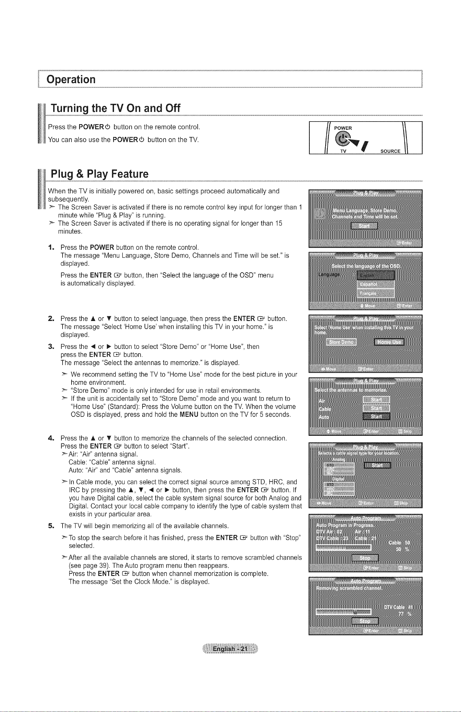
When the TV is initially powered on, basic settings proceed automatically and
subsequently.
>- The Screen Saver is activated if there is no remote control key input for longer than 1
minute while "Plug & Play" is running.
>_ The Screen Saver is activated if there is no operating signal for longer than 15
minutes.
1 Press the POWER button on the remote control.
The message "Menu Language, Store Demo, Channels and Time will be set." is
displayed.
SOURCE_I
Press the ENTER C_ button, then "Select the language of the OSD" menu
is automatically displayed.
=
Press the A or T button to select language, then press the ENTER I:_ button.
The message "Select 'Home Use' when installing this TV in your home." is
displayed.
1
Press the 41or _ button to select "Store Demo" or "Home Use", then
press the ENTER _ button.
The message "Select the antennas to memorize." is displayed.
>- We recommend setting the TV to "Home Use" mode for the best picture in your
home environment.
>_ "Store Demo" mode is only intended for use in retail environments.
>- If the unit is accidentally set to "Store Demo" mode and you want to return to
"Home Use" (Standard): Press the Volume button on the TV. When the volume
OSD is displayed, press and hold the MENU button on the TV for 5 seconds.
4, Press the A or T button to memorize the channels of the selected connection.
Press the ENTER E3_button to select "Start".
>-Air: "Air" antenna signal.
Cable: "Cable" antenna signal.
Auto: "Air" and "Cable" antenna signals.
>-In Cable mode, you can select the correct signal source among STD, HRC, and
IRC by pressing the A, T, 4 or I_ button, then press the ENTER _ button. If
you have Digital cable, select the cable system signal source for both Analog and
Digital. Contact your local cable company to identify the type of cable system that
exists in your particular area.
5, The TV will begin memorizing all of the available channels.
>-To stop the search before it has finished, press the ENTER G_ button with "Stop"
selected.
>_After all the available channels are stored, it starts to remove scrambled channels
(see page 39). The Auto program menu then reappears.
Press the ENTER C_ button when channel memorization is complete.
The message "Set the Clock Mode." is displayed.
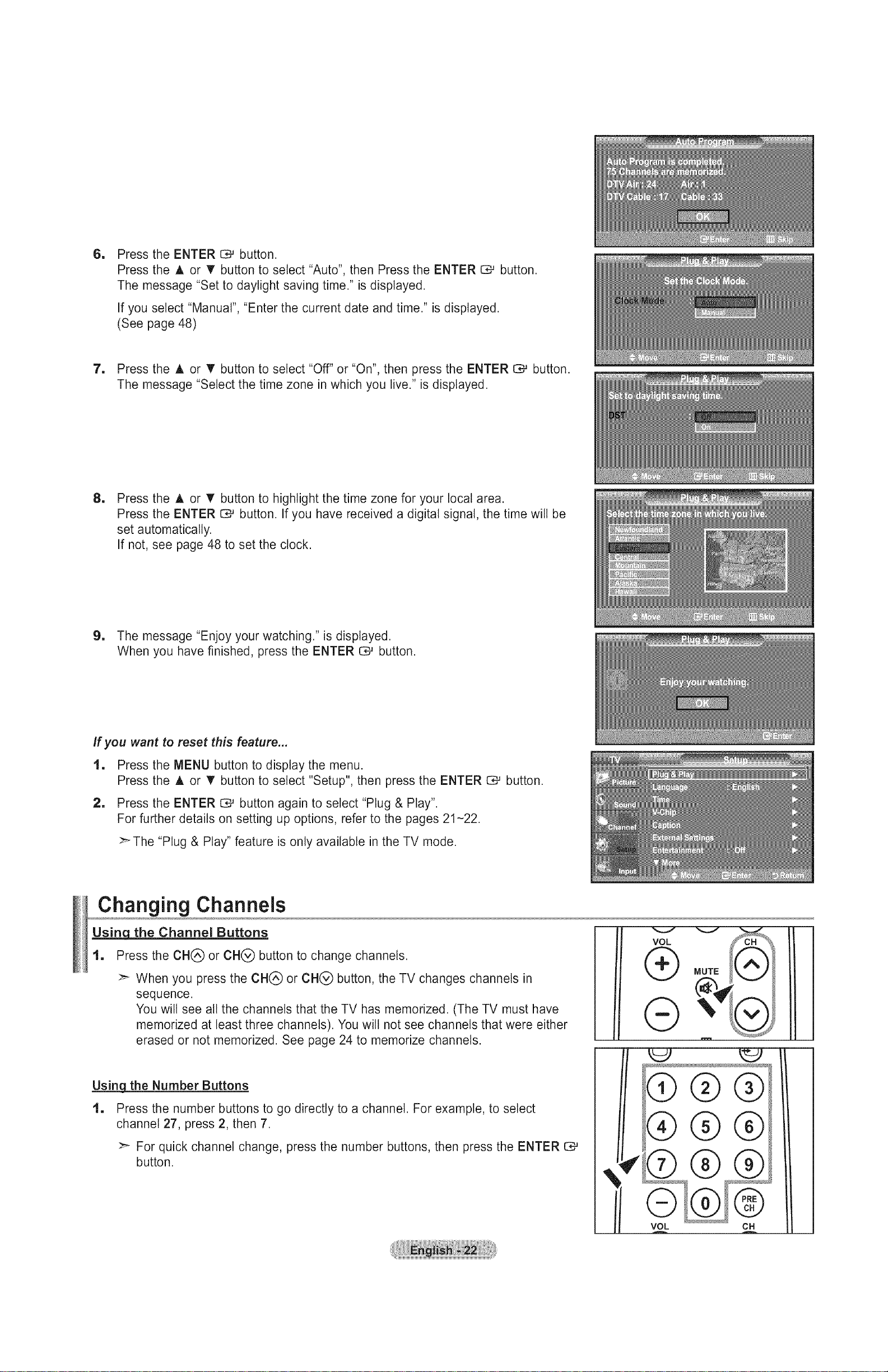
I Press the ENTER _ button.
Press the A or T button to select "Auto", then Press the ENTER C# button.
The message "Set to daylight saving time." is displayed.
If you select "Manual", "Enter the current date and time." is displayed.
(See page 48)
7. Press the A or T button to select "Off" or "On", then press the ENTER C,_ button.
The message "Select the time zone in which you live." is displayed.
I
Press the A or T button to highlight the time zone for your local area.
Press the ENTER O*-'button. If you have received a digital signal, the time will be
set automatically.
If not, see page 48 to set the clock.
9. The message "Enjoy your watching." is displayed.
When you have finished, press the ENTER C,# button.
If you want to reset this feature...
1. Press the MENU button to display the menu.
Press the A or T button to select "Setup", then press the ENTER _ button.
2. Press the ENTER G_ button again to select "Plug & Play".
For further details on setting up options, refer to the pages 21-22.
>-The "Plug & Play" feature is only available in the TV mode.
Changing Channels
Us_s_]8_qthe Channel Buttons
1. Press the CHQ or CH(_ button to change channels.
>_ When you press the CH(_ or CH(_ button, the TV changes channels in
sequence.
You will see all the channels that the TV has memorized. (The TV must have
memorized at least three channels). You will not see channels that were either
erased or not memorized. See page 24 to memorize channels.
VOL
®
®
!
Using_ the Number Buttons
1. Press the number buttons to go directly to a channel. For example, to select
channel 27, press 2, then 7.
>_ For quick channel change, press the number buttons, then press the ENTER
button.
®®®
®®®
¢
db®®
I
VOL CH
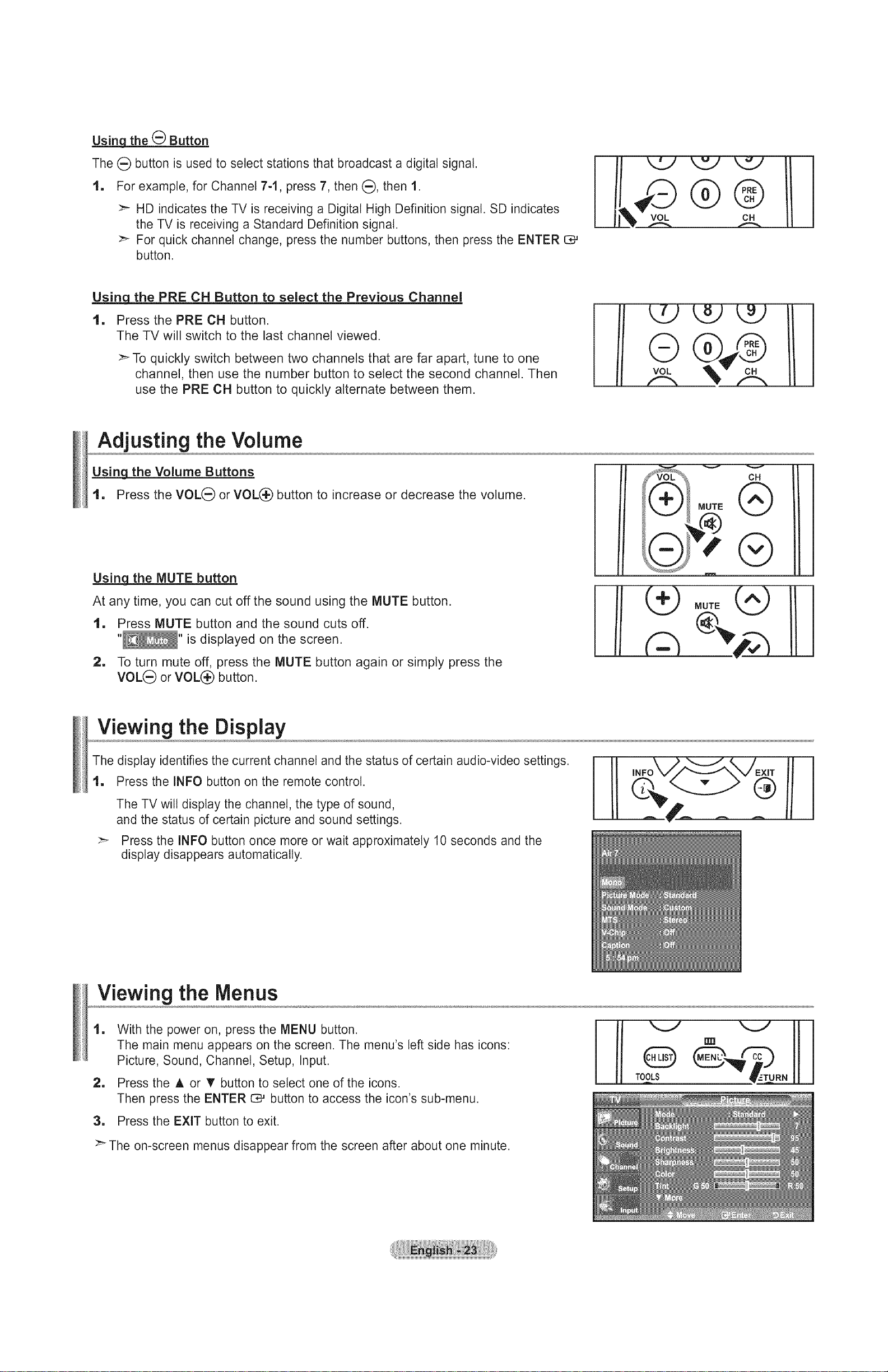
Usinq the (_ Button
The (_) button is used to select stations that broadcast a digital signal.
1, For example, for Channel 7-1, press 7, then (:_),then 1.
>'- HD indicates the TV is receiving a Digital High Definition signal. SD indicates
the TV is receiving a Standard Definition signal.
>_ For quick channel change, press the number buttons, then press the ENTER C#
button.
Using the PRE CH Button to select the Previous Channel
1. Press the PRE CH button.
The TV will switch to the last channel viewed.
:_ To quickly switch between two channels that are far apart, tune to one
channel, then use the number button to select the second channel. Then
use the PRE CH button to quickly alternate between them.
Adjusting the Volume
the Volume Buttons
1. Press the VOL(_ or VOL(_ button to increase or decrease the volume.
Using_ the MUTE button
At any time, you can cut off the sound using the MUTE button.
1. Press MUTE button and the sound cuts off.
"_" is displayed on the screen.
i
i
i
i
i
i
i
i
i
i
i
i
i
I
CH
MUTE
®
®
i
2. To turn mute off, press the MUTE button again or simply press the
VOL_) or VOL(_ button.
Viewing the Display
The display identifies the current channel and the status of certain audio-video settings.
1, Press the INFO button on the remote control.
The TV will display the channel, the type of sound,
and the status of certain picture and sound settings.
:_ Press the INFO button once more or wait approximately 10 seconds and the
display disappears automatically.
Viewing the Menus
1
With the power on, press the MENU button.
The main menu appears on the screen. The menu's left side has icons:
Picture, Sound, Channel, Setup, Input.
1
Press the A or '_ button to select one of the icons.
Then press the ENTER 1:_ button to access the icon's sub-menu.
3, Press the EXIT button to exit.
>" The on-screen menus disappear from the screen after about one minute.
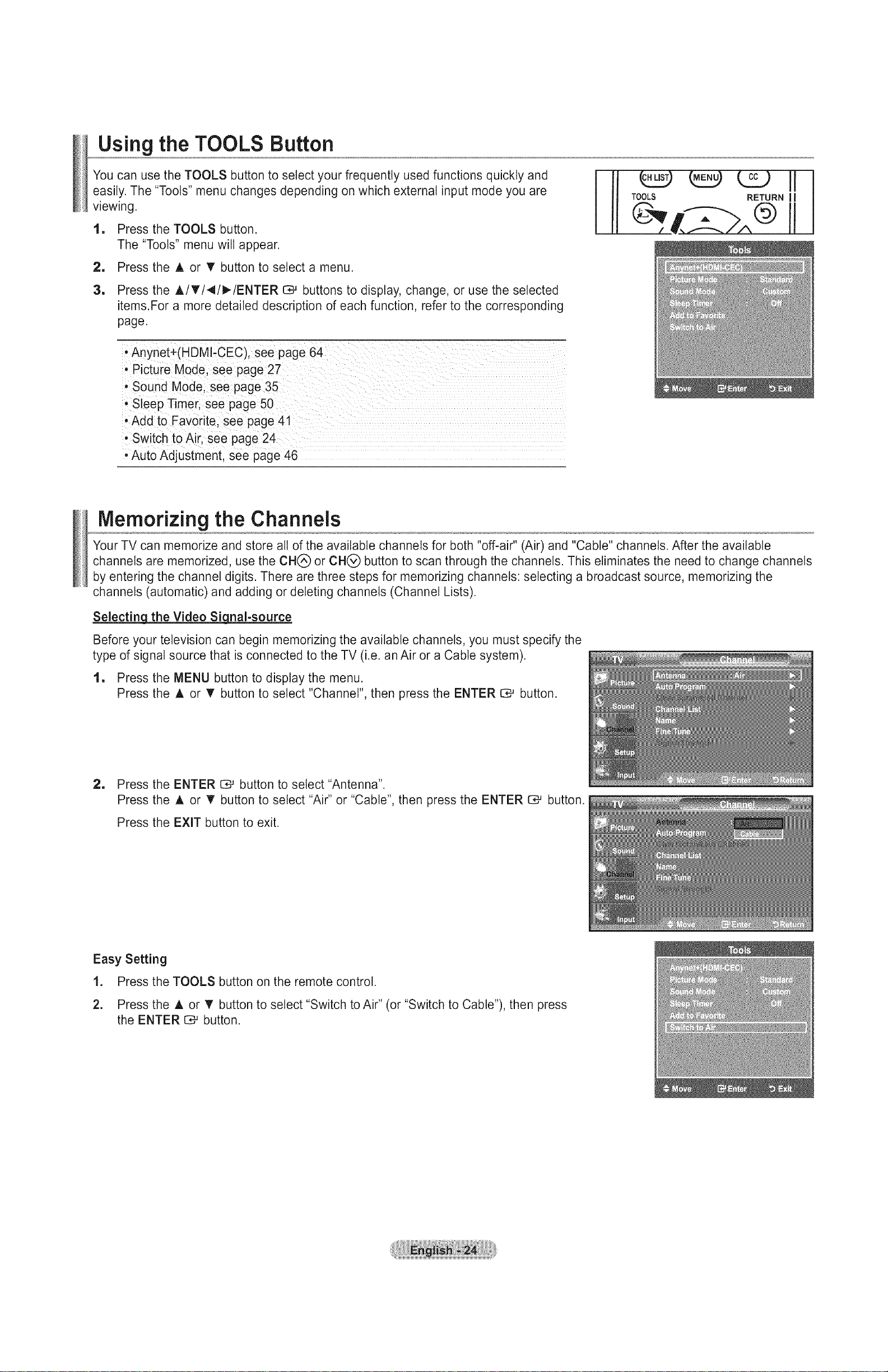
Using the TOOLS Button
You can use the TOOLS button to select your frequently used functions quickly and
easily, The "Tools" menu changes depending on which external input mode you are
viewing,
1, Press the TOOLS button.
The "Tools" menu will appear.
2, Press the A or T button to select a menu.
1
Press the A/T/4/_/ENTER C*-'buttons to display, change, or use the selected
items.For a more detailed description of each function, refer to the corresponding
page.
• Anynet+(HDMl-CEC), see page 64
• Picture Mode, see page 27
• Sound Mode, see page 35
• Sleep Timer, see page 50
, Add to Favorite. see page 41
• Switch to Air, see page 24
•Auto Adjustment, see page 46
Memorizingthe Channels
Your TV can memorize and store all of the available channels for both "off-air" (Air) and "Cable" channels. After the available
channels are memorized, use the CH(_) or CH(_) button to scan through the channels. This eliminates the need to change channels
by entering the channel digits. There are three steps for memorizing channels: selecting a broadcast source, memorizing the
channels (automatic) and adding or deleting channels (Channel Lists).
Selecting! the Video Siqnal-source
Before your television can begin memorizing the available channels, you must specify the
type of signal source that is connected to the TV (i.e. an Air or a Cable system).
1, Press the MENU button to display the menu.
Press the A or V' button to select "Channel", then press the ENTER _ button.
2, Press the ENTER _ button to select "Antenna".
Press the ,_, or T button to select "Air" or "Cable", then press the ENTER _ button.
Press the EXIT button to exit.
Easy Setting
1. Press the TOOLS button on the remote control.
2. Press the A or _' button to select "Switch to Air" (or "Switch to Cable"), then press
the ENTER _ button.
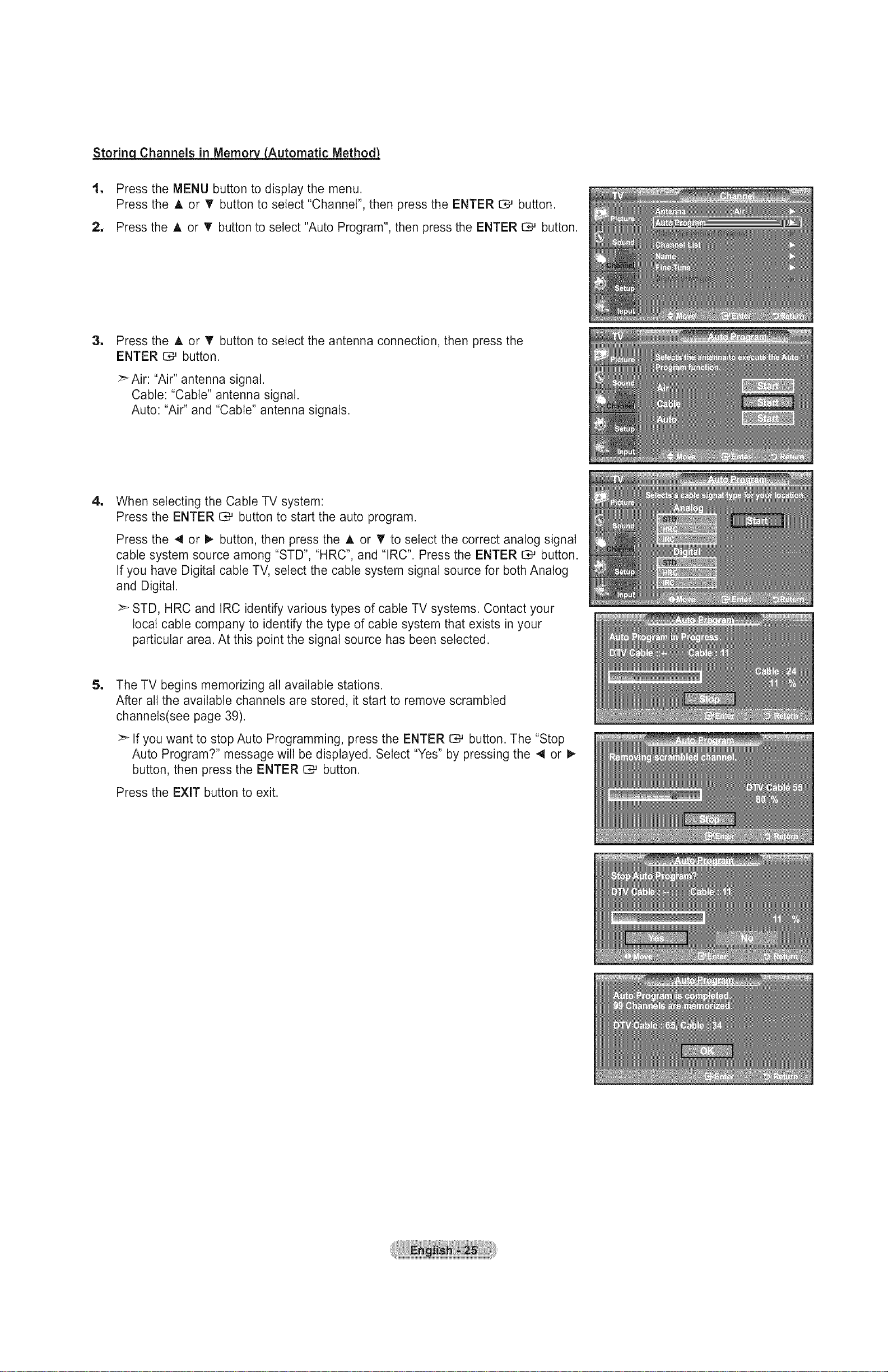
Storing Channels in Memory__Automatic MethodJ
1. Press the MENU button to display the menu.
Press the A or • button to select "Channel", then press the ENTER C*_ button.
2, Press the A or 'V' button to select "Auto Program", then press the ENTER C# button.
1
Press the A or V" button to select the antenna connection, then press the
ENTER C_ button.
>_Air: "Air" antenna signal.
Cable: "Cable" antenna signal.
Auto: "Air" and "Cable" antenna signals.
1
When selecting the Cable TV system:
Press the ENTER I:_ button to start the auto program.
Press the 4 or I_ button, then press the A or _' to select the correct analog signal
cable system source among "STD", "HRC", and "IRC". Press the ENTER C;#button.
If you have Digital cable TV, select the cable system signal source for both Analog
and Digital.
:_ STD, HRC and IRC identify various types of cable TV systems. Contact your
local cable company to identify the type of cable system that exists in your
particular area. At this point the signal source has been selected.
1
The TV begins memorizing all available stations.
After all the available channels are stored, it start to remove scrambled
channels(see page 39).
If you want to stop Auto Programming, press the ENTER C# button. The "Stop
Auto Program?" message wilt be displayed. Select "Yes" by pressing the 4 or I_
button, then press the ENTER C# button.
Press the EXIT button to exit.
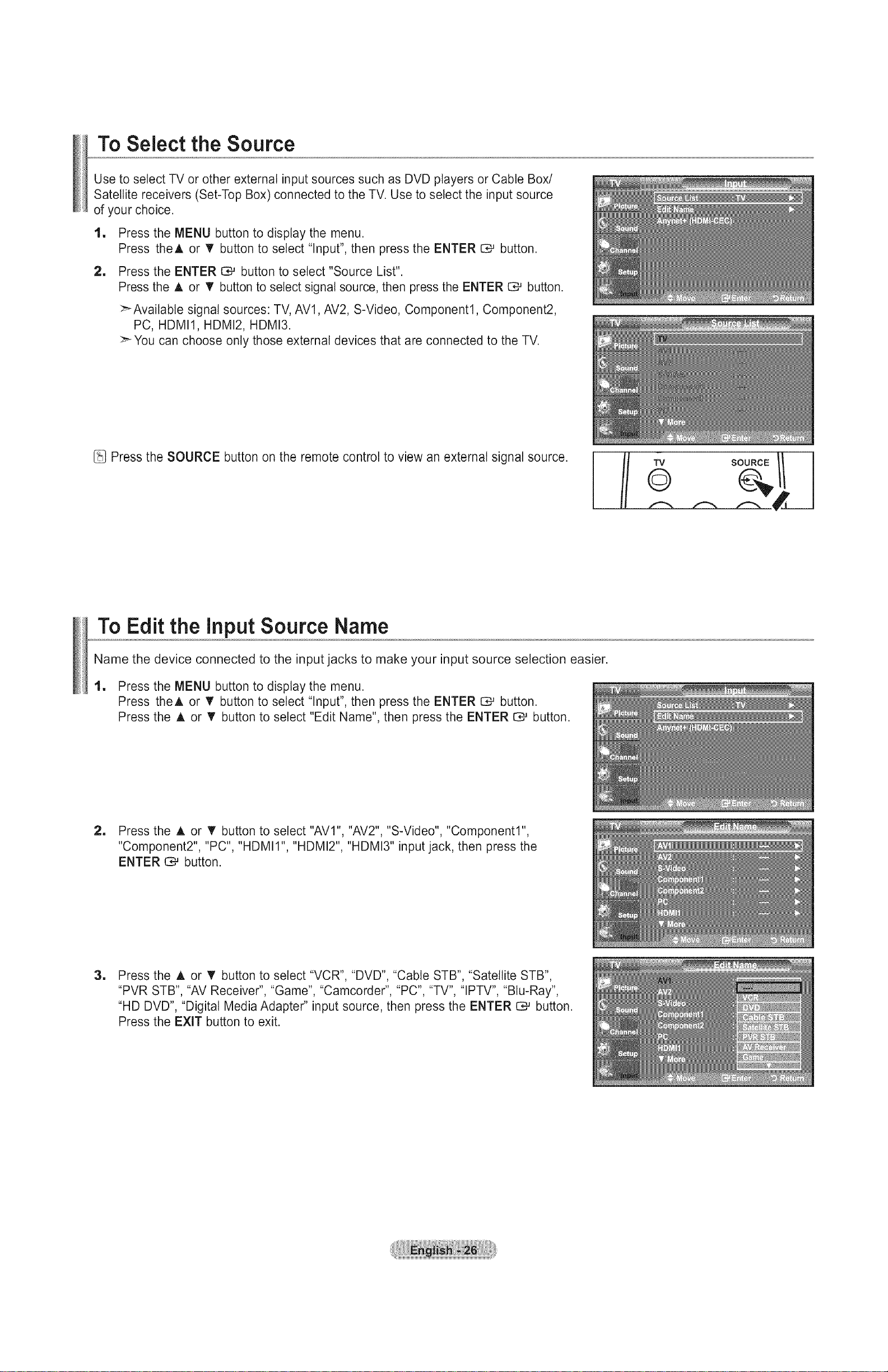
To Select the Source
Use to select TV or other external input sources such as DVD players or Cable Box/
Satellite receivers (Set-Top Box) connected to the TV. Use to select the input source
of your choice.
1, Press the MENU button to display the menu.
Press theA or V' button to select "Input", then press the ENTER O# button.
1 Press the ENTER C_ button to select "Source List".
Press the A or V' button to select signal source, then press the ENTER I:_ button.
>-Available signal sources: TV, AVl, AV2, S-Video, Component1, Component2,
PC, HDMI1, HDMI2, HDMI3.
You can choose only those external devices that are connected to the TV.
Press the SOURCE button on the remote control to view an external signal source.
To Edit the input Source Name
Name the device connected to the input jacks to make your input source selection easier.
1, Press the MENU button to display the menu.
Press theA or V' button to select "Input", then press the ENTER CM button.
Press the A or V' button to select "Edit Name", then press the ENTER _ button.
TV
©
SOURCE // I
2, Press the A or • button to select "AVl", "AV2", "S-Video", "Component1"
"Component2", "PC", "HDMII", "HDMI2", "HDMI3" input jack, then press the
ENTER C_ button.
1
Press the A or _' button to select "VCR", "DVD", "Cable STB", "Satellite STB",
"PVR STB", "AV Receiver", "Game", "Camcorder", "PC", "TV", "IPTV", "Blu-Ray",
"HD DVD", "Digital Media Adapter" input source, then press the ENTER CM button.
Press the EXIT button to exit.
Picture Control
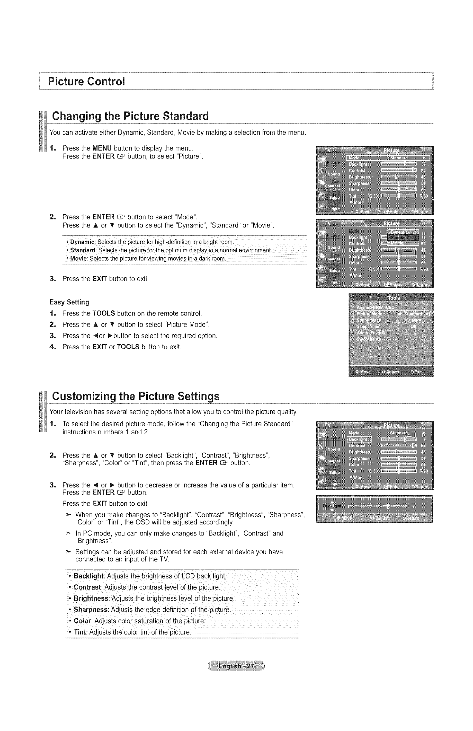
Changing the Picture Standard
You can activate either Dynamic, Standard, Movie by making a selection from the menu.
1. Press the MENU button to display the menu.
Press the ENTER C*_ button, to select "Picture".
2, Press the ENTER _ button to select "Mode".
Press the A or T button to select the "Dynamic", "Standard" or "Movie".
* Standardl Se!ects the picture for the optimum disp!ay in a no[ma! env!ronment.
+Movie; Selects the picture for viewing movies in adark room
3. Press the EXIT button to exit.
Easy Setting
1, Press the TOOLS button on the remote control.
2, Press the A or V' button to select "Picture Mode".
3, Press the 4or !_button to select the required option.
4, Press the EXIT or TOOLS button to exit.
Customizing the Picture Settings
Your television has several setting options that allow you to control the picture quality.
1, To select the desired picture mode, follow the "Changing the Picture Standard"
instructions numbers 1 and 2.
2, Press the A or T button to select "Backlight", "Contrast", "Brightness",
"Sharpness", "Color" or "Tint", then press the ENTER I:_ button.
=
Press the 41 or 1_ button to decrease or increase the value of a particular item.
Press the ENTER _ button.
Press the EXIT button to exit.
:_ When you make changes to "Backlight", "Contrast", "Brightness", "Sharpness",
"Color" or "Tint", the OSD will be adjusted accordingly.
:_ In PC mode, you can only make changes to "Backlight", "Contrast" and
"Brightness".
:_ Settings can be adjusted and stored for each external device you have
connected to an input of the TV.
- Backlight: Adjusts the brightness of LCD back light.
• Contrast: Adjusts the contrast level of the picture.
• Brightness: Adjusts the brightness level of the picture.
• Sharpness: Adjusts the edge definition of the picture.
, Color: Ad usts color saturation of the picture.
- Tint: Adjusts the color tint of the picture.
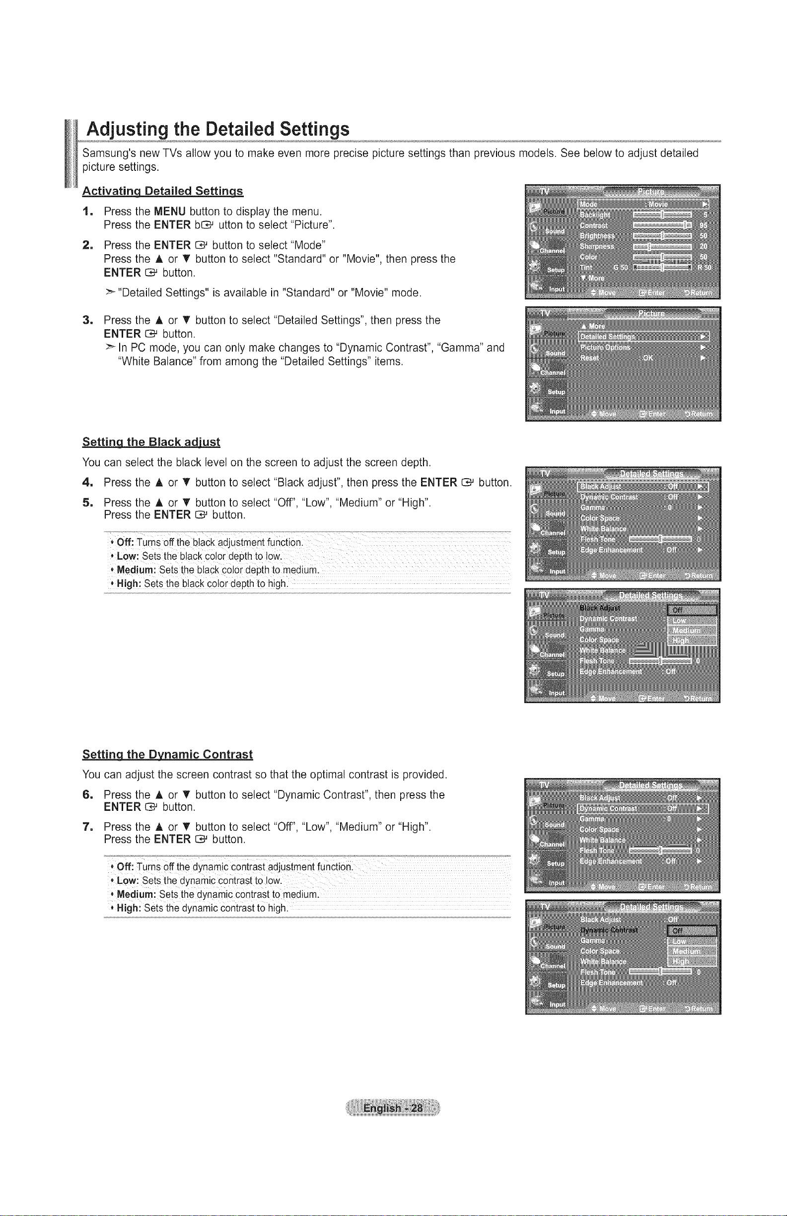
Adjusting the Detailed Settings
Samsung's new TVs allow you to make even more precise picture settings than previous models. See below to adjust detailed
picture settings.
Activating_ Detailed Settinq._
1, Press the MENU button to display the menu.
Press the ENTER bO_ utton to select "Picture".
2, Press the ENTER _ button to select "Mode"
Press the A or _' button to select "Standard" or "Movie", then press the
ENTER 0.-' button.
>-"Detailed Settings" is available in "Standard" or "Movie" mode.
1
Press the A or T button to select "Detailed Settings", then press the
ENTER 1:_ button.
>-In PC mode, you can only make changes to "Dynamic Contrast", "Gamma" and
"White Balance" from among the "Detailed Settings" items.
Settinq the Black ad_
You can select the black level on the screen to adjust the screen depth.
4, Press the A or V button to select "Black adjust", then press the ENTER _ button.
5, Press the A or T button to select "Off", "Low", "Medium" or "High".
Press the ENTER _ button.
*Medium! Sets the black co!or depth to medium
* High: Sets the black co!or depth to high.
Setting the Dynamic Contrast
You can adjust the screen contrast so that the optimal contrast is provided.
6, Press the A or • button to select "Dynamic Contrast", then press the
ENTER O# button.
7, Press the A or T button to select "Off", "Low", "Medium" or "High".
Press the ENTER _ button.
* Medium: Sets the dynamic contrast to medium.
High: Sets the dynamic contrast to high:
 Loading...