

Samsung 430 Series, 450 Series, LN26D450G1D, LN26D430G3D, LN32D450G1D User Manual
...
LCD TV
SERIES
LJ.50
LJ.30
lfl
User
1
.------------------,11
1
I
. I:
Manual
I .
imagine
Thank
To
your
www.samsung.com/register
Model
you
receive
product
for
purchasing
more
at
the
complete
Serial
possibilities
this
Samsung
service,
No.
please
product.
register
_
For
more
Figures
Product
information
and
illustrationsinthis
design
and
about
User
specifications
howtouse
Manual
maybechanged
are
e-Manual
provided
Important Warranty Information Regarding Television Format Viewing
~
See
the
warranty
card
for
more
Wide
screen
format
LCD
motion
video.
offers
expanded standard
Additionally,
graphics
can
cause
programming
sizing
Be
carefulinthe
as
burned-in
•
The
this
feature
viewing
and
patterns,
uneven
and
features,
SAMSUNG
Subjecttothe
(SAMSUNG)
Warranty
purchasedinthe
The
Limited
from
workmanship,
Excluded,
exchangesorreplacements,
For
-Inthe United States: 1-800-SAMSUNG (1-800-726-7864)
-
use
images,
Repair
abcve described
Warranty
the
Service
but
the locationofa
In
Canada: 1-800-SAMSUNG
Displays
images
displayedonthem
and
the
images
format
television
other
stationary
shouldbelimitedasdescribed
agingofLCD
images,
and
these
controlstoview
selection
and
are
not
ELECTRONICS
recuirements,
products,
Serviceinthe
United
warranty
Statement
Centeristhe
and
only
not
limited
SAMSUNG
informationonwarranty
(16:9.
the aspect
are
constantly
video
and
images
Displays
primarily
durationoftelevision
coveredbyyour
and
States,
those
to,
that
display
different
NORTH
AMERICAN
conditions, exclusions
the
recuirements, conditions,
United
StatesonSAMSUNG
for
the
warranty
repairs
and
are
accessories,
mustbeperformedbya
a dated
responsibilityofthe
encounteredinnormal
any
originally
Authorized
ratioofthe
should
primarilybein
moving.
programming,
and
text
suchasstock
above
leave
subtle,
full
screen
formatsasa
formats
Samsung
BillofSaleasProofofPurchase
limited
LIMITED
period
purchaser.
specified
options,
upgrades,orconsumables.
Service
(P.
for
reference
without
notice.
terms.
screen
widthtoheight)
the
Displaying
for
but
moving
you
and
limitationsofthe
originally
useofthe
provisions
Center,
wide
stationary
shouldbelimitedtono
market
all
televisions.
permanent
images,
full
screen
use
for
viewing.
warranty.
WARRANTY
exclusions
products
specified,
SAMSUNG
Conditions
product.
for,
please
call
12)
only
and
are
screen
graphics
reports,
Displaying
burned-in
not
stationary
picture.
Uneven
STATEMENT
original
and
limitations
purchasedinCanada,
andtothe
Authorized
mustbepresentedtothe
covered
in-homeoron-site
toll-free:
primarily
16:9
ratio
and
more
video
game
stationary
ghost
patternsordark
LCD
Limited
contained
Original
are
limited
may
differ
from
actual
designedtoview
format,orexpandedtofill
imagesonscreen,
than5%of
displays,
images
imagesinthe
agingasa
Warranty
herein,
andinCanadaonSAMSUNG
Purchaser
Service
Center.
only
to manufacturing defectsinmaterial
services,
suchasthe
the
total
television
station
that
exceed
LCD
picture.Toavoid
bars.OnLCD
resultofformat
supplied
with
SAMSUNG
only.
Along
Service
Center.
minimumormaximum
product
wide
screen
the
screenifyour
dark
viewing
logos,
web
the
above
models
selection
Samsung
will
additionally
with
this
Statement,
Transportationtoand
appearance.
format
full-
per
week.
guidelines
vary
offer
and
use,aswell
provide
the
times,
model
the
picture
Original
or
sidebarsonnon-
sitesorcomputer
this,
that
Electronics
products
repair
Avoid
displaying
etc.),orprogramsinpanoramaor4:3
which
will
•
Avoid
•
Always
•
Reduce
values
Frequently
•
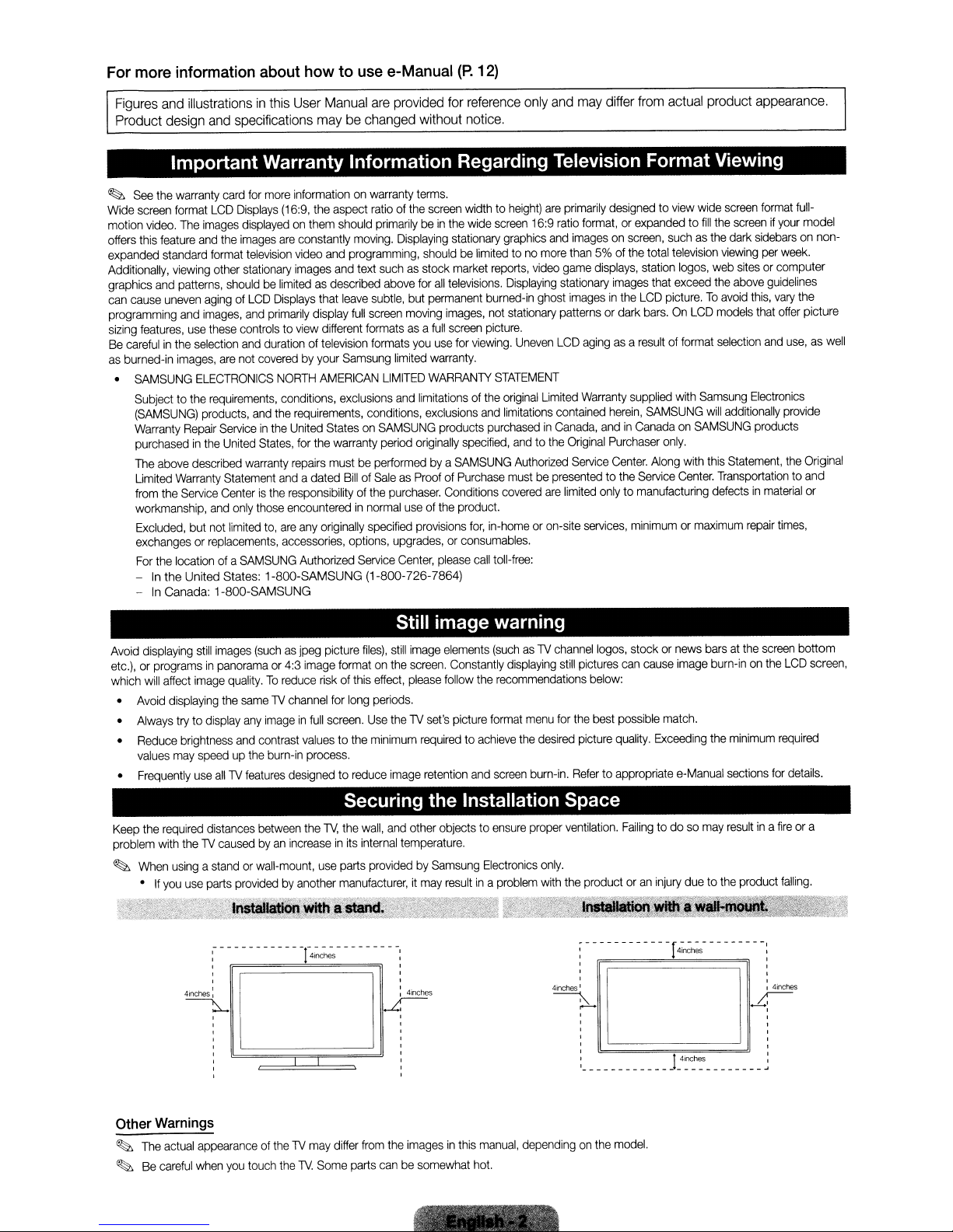
Keep
the
problem
~
When
•Ifyou
still
images
(suchasjpeg picture
affect
image
quality.Toreduce
displaying
may
recuired
with
usingastandorwall-mount,
the
sameTVchannel
try to
display
any
imageinfull
brightness
theTVcausedbyan
use
and
speedupthe
use
distances
parts
~------------!-~----------~
I
, ,
, ,
, ,
, ,
contrast
burn-in
allTVfeatures
between
providedbyanother
designed to
increaseinits
~
Still image warning
image
formatonthe
risk
of this
for
long
screen.
valuestothe
process.
reduce
effect,
periods.
Use
theTVset's
minimum
image
elements
screen.
please
follow
requiredtoachieve
retention
Constantly
the
picture
format
and
(suchasTV
displaying
recommendations
the
screen
files),
still
image
Securing the Installation Space
the
TV,
the
wall,
and
internal
use
parts
providedbySamsung
manufacturer,itmay
41nches
other objects to
temperature.
I
~
,
,
,
,
,
,
,
,
resultina
ensure
Electronics
problem
menu
desired
burn-in.
proper
only.
with
channel
logos,
still
pictures
for
the
picture
Refer
ventilation.
the
productoran
:-- --- ---
, ,
, ,
, ,
4inches
I I
~
:--
,
,
,
, ,
, ,
, !4nches I
I
stockornews
can
cause
below:
best
possible
quality.
to appropriate
Failing
-------------------~
image
match.
Exceeding
e-Manual
to dosomay
injury
duetothe
----r4i~h~-
barsatthe
burn-inonthe
the
minimum
sections
resu~
inafireora
product
---
-----:
;;-
~l
screen
required
for
falling.
4inches
bcttom
LCD
details.
screen,
Other
Warnings
~
The
actual
appearanceoftheTVmay
~
Be
careful
when
you
touch
theTVSome
differ
from
parts
the
imagesinthis
canbesomewhat
manual,
hot.
dependingonthe
model.
~
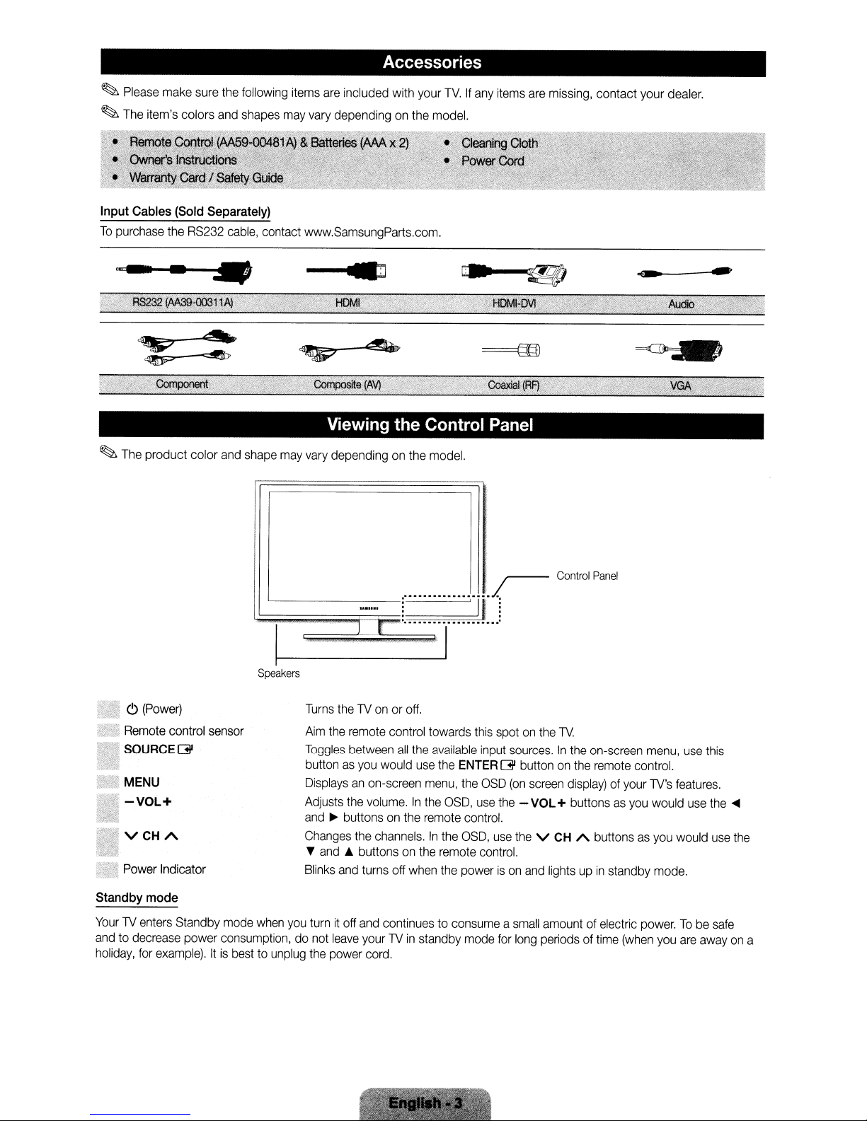
Please
~
The
Input
To
purchase
make
item's colors
Cables
(Sold
the
sure
and
Separately)
RS232
the
cable,
following
shapes
contact
items
are
included with
may
vary
dependingonthe
www.SamsungParts.com
Accessories
your
TV.Ifany
model.
.
items
are
missing,
contact your
dealer.
..".._~._
~
The
...
product color
-.
and
Viewing the Control Panel
shape
may
vary
I
'------r
'C;;;;;;;;;;;"'A",~"
Speakers
dependingonthe
r .
~~>w'
model.
I
··
..
jrr
Control
Panel
o
(Power)
•
Remote
iSOURCEGl
'.
MENU
."
-VOL+
VCHA
Power
Standby
YourlVenters
andtodecrease
holiday,
control
Indicator
mode
Standby
for
example).Itis
sensor
mode
power
consumption,donot
besttounplug
when
you
Turns
thelVonoroff.
Aim
the
remote
control
Toggles
buttonasyou
Displaysanon-screen
Adjusts
and~buttonsonthe
Changes
•
Blinks
between
the
the
and
A buttonsonthe
and
turnitoff
leave
the
power
all
would
volume.Inthe
channels.Inthe
turns
off
when
and
continuestoconsumeasmall
yourlVin
cord.
towards
the
available
use
menu,
remote
standby
the
ENTER
the
OSD,
control.
OSD,
remote
the
powerison
mode
this
spotonthe
input
G button
OSD
use
the
use
control.
for
lV.
sources.Inthe
(on
screen
- VOL+ buttonsasyou
the
V
and
amountofelectric
long
periodsoftime
on-screen
on
the
remote
display)ofyour
CH
A buttons
lightsupin
standby
menu,
control.
lV's
would
as
you
mode.
power.Tobe
(when
you
use
this
features
use
would
are
awayona
the
use
safe
.
....
the
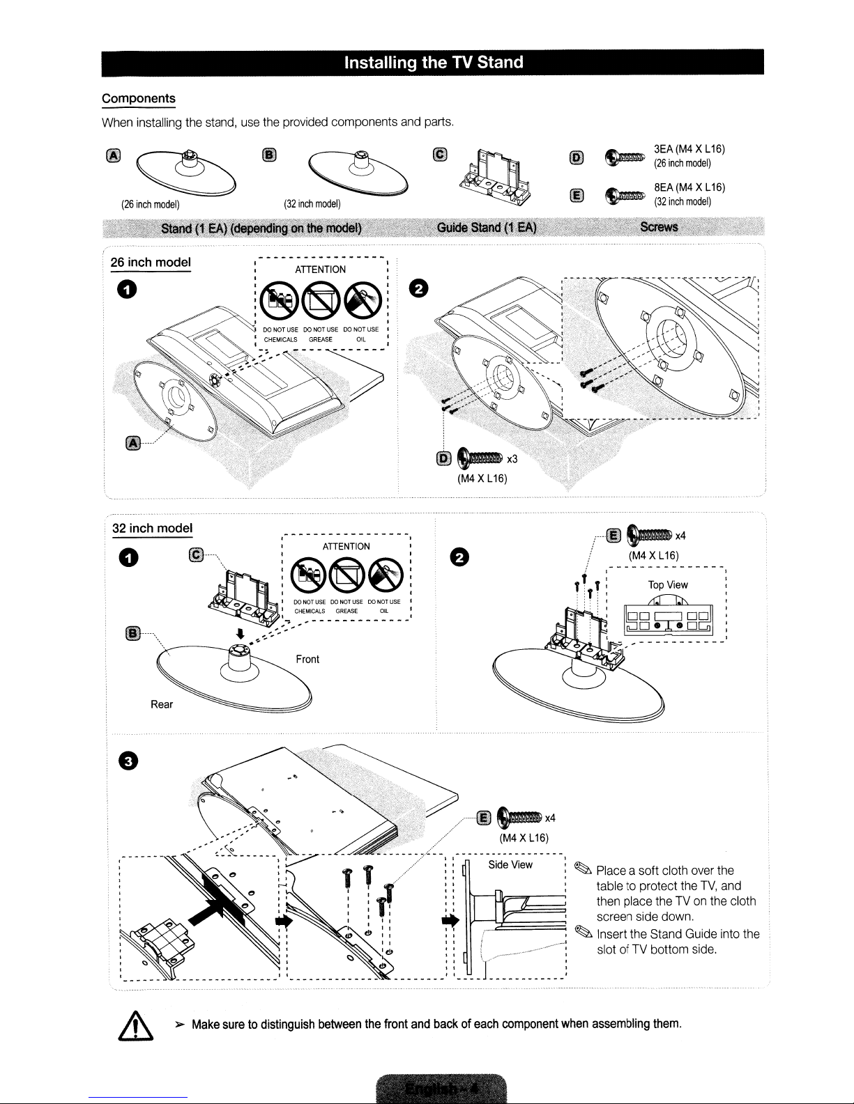
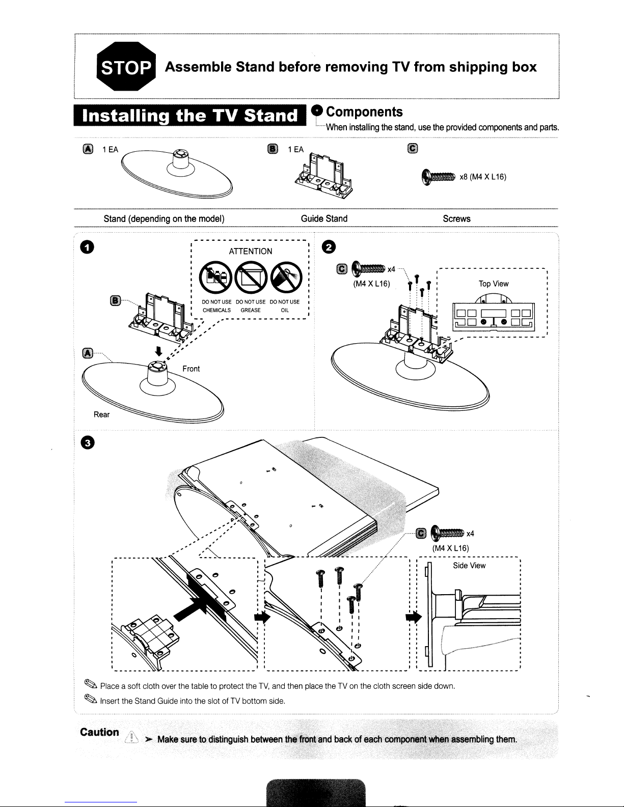
Components
When
installing
the
stand,
use
the
provided
Installing the TV Stand
components
and
parts.
(i)
~
(26
inch
model)
26
inch model
o
32
inch model
o
f~l····
.....
"
~
~
(32
inch
model)
ATIENTION I
i®@~ie
, I
, ,
@".." : ATIENTION :
........
~
--f.'.~
~@®~~
,
o • I
..
OOHQTUSE DONQTUSE OOHQTUSE I
CHEMICALS
I ,
~"
,,':";'
---------------
GREASE:
1
OIL
~
~
@SJm-X3'
(M4XL16)
I
@
00
T,
:
3EA(M4 XL
(26
inch
8EA
(32
inch
SJm-
(~~
~_L~~
Top
View
r·t§)
/
t :
TI
,T:
~
~
:
,
,
~B:@'B~
(M4
x4
model)
X L
model)
16)
16)
_
:
Rear
e
&
»Make
suretodistinguish
between
the
front
and
backofeach
···OO~X4
(M4XL16)
~
~
component
when
Place
a soft cloth
table to protect
then
place
theTVon
screen
side
Insert
the
Stand
slotofTV
assembling
bottom
them.
the
down.
over
TV,
Guide
side.
the
the
and
into
cloth
the
Installing the Wall Mount
WallorCeiling
The
product
mounted,
Installing
The
For
technician
productorinjurytoyourselforothersifyou
Wall
Install
than
wall,itmay
wall
mount
detailed
Mount
your
plaster
the
Wall
Mount
kit
(sold
informationoninstalling
for
assistance
Kit
Specifications
wall
mountona
board.
please
fall
and
resultinsevere
Mounting
shouldbemountedona
the
product
may
slideorfall,
Kit
separately)
when
contact
solid
allows
the
wall
installing
the
(VESA)
wall
perpendiculartothe
your
nearest
personal
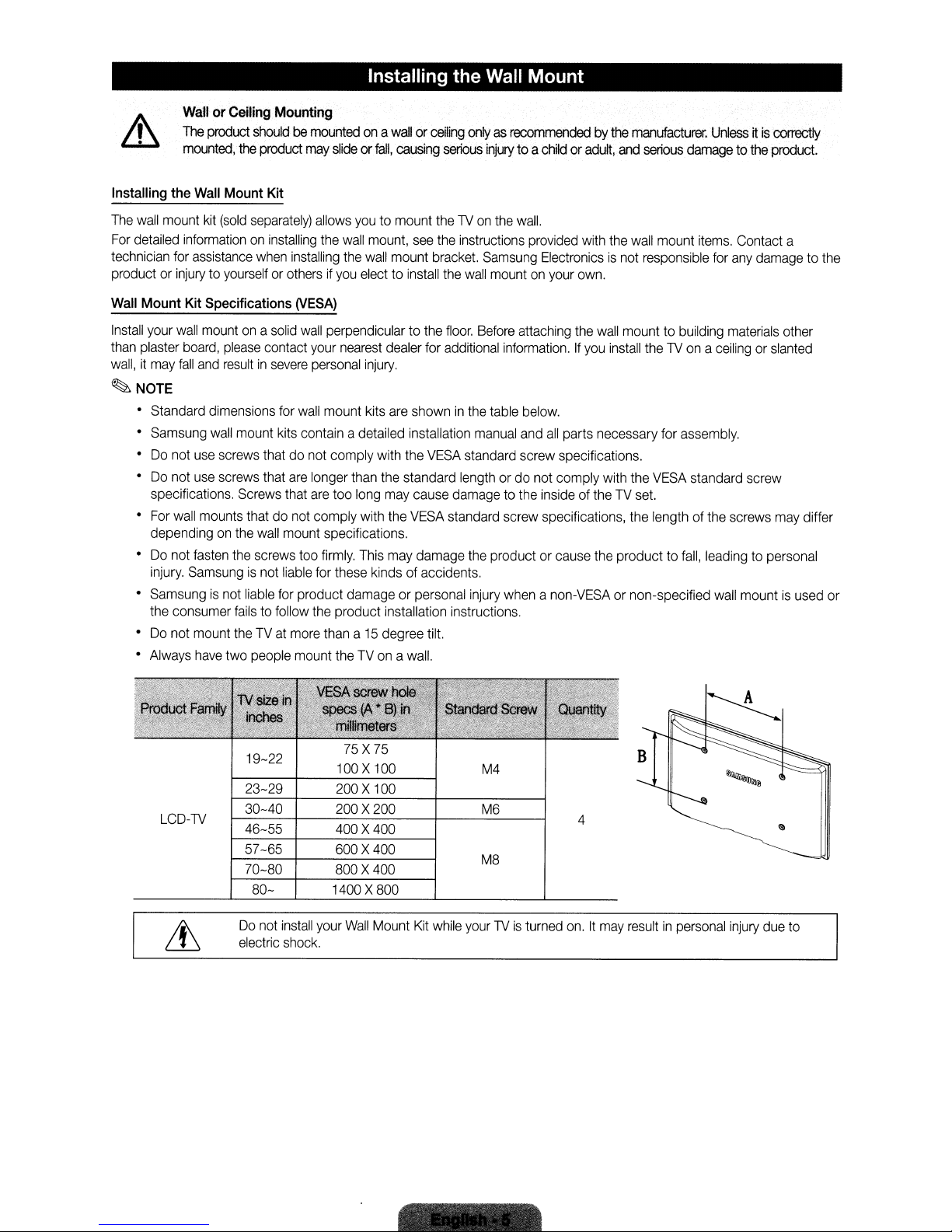
~NOTE
• Standard dimensions
•
Samsung
•Donot
•
Do
specifications.
•
For
dependingonthe
•Donot
injury.
•
Samsungisnot
the
•
Do
•
Always
wall
use
screws
not
use
screws
wall
mounts
fasten
Samsungisnot
consumer
not
mount
have
two
for
mount
kits
thatdonot
that
are
Screws
that
thatdonot
wall
mount
the
screws
liable
liable
for
failstofollow
theTVat
people
wall
mount kits
contain
comply with
longer
are
too
comply
specifications.
too
firmly.
for
these
product damage or
the
product installation instructions.
more
thana15
mount
theTVonawall.
wallorceiling
causing
youtomount
mount,
wall
mount
electtoinstall
dealer
injury.
are
adetailed installation
than
the
long
may
with
the
This
may
kinds
degree
serious
the1Von
see
the
bracket.
the
floor.
for
additional
showninthe
the
VESA
standard
cause
damagetothe
VESA
standard screw specifications,
damage
of accidents.
personal
tilt.
onlyasrecommendedbythe
injury
to a
childoradult,
the
wall.
instructions
wall
Before
manual
standard screw specifications.
lengthordo
the
injury
provided
Samsung
mountonyour
table
productorcause
Electronicsisnot
attaching
information.Ifyou
below.
and
all
parts necessary for
not comply with the
insideoftheTVset.
whenanon-VESAornon-specified
with
own.
the
and
the
wall
install
the
product to
manufacturer.
serious
wall
mount
responsible
mounttobuilding
the1Vonaceilingorslanted
VESA
the
length of
Unlessitis
damage
assembly.
fall,
to the
items.
Contact a
for
any
materials
standard screw
the
screws
leadingtopersonal
wall
mountisused
damagetothe
correctly
product.
other
may
differ
or
LCD-1V
19-22
23-29
30-40
46-55
57-65
70-80
80-
Do
not
electric
install
shock.
75X75
100X100
200X100
200X200
400X400
600X400
800X400
1400X800
your
Wall
Mount
Kit
while
M4
M6
M8
your1Vis
turned
4
on.Itmay
resultinpersonal
injury
due
to
Remote Control Buttons
~
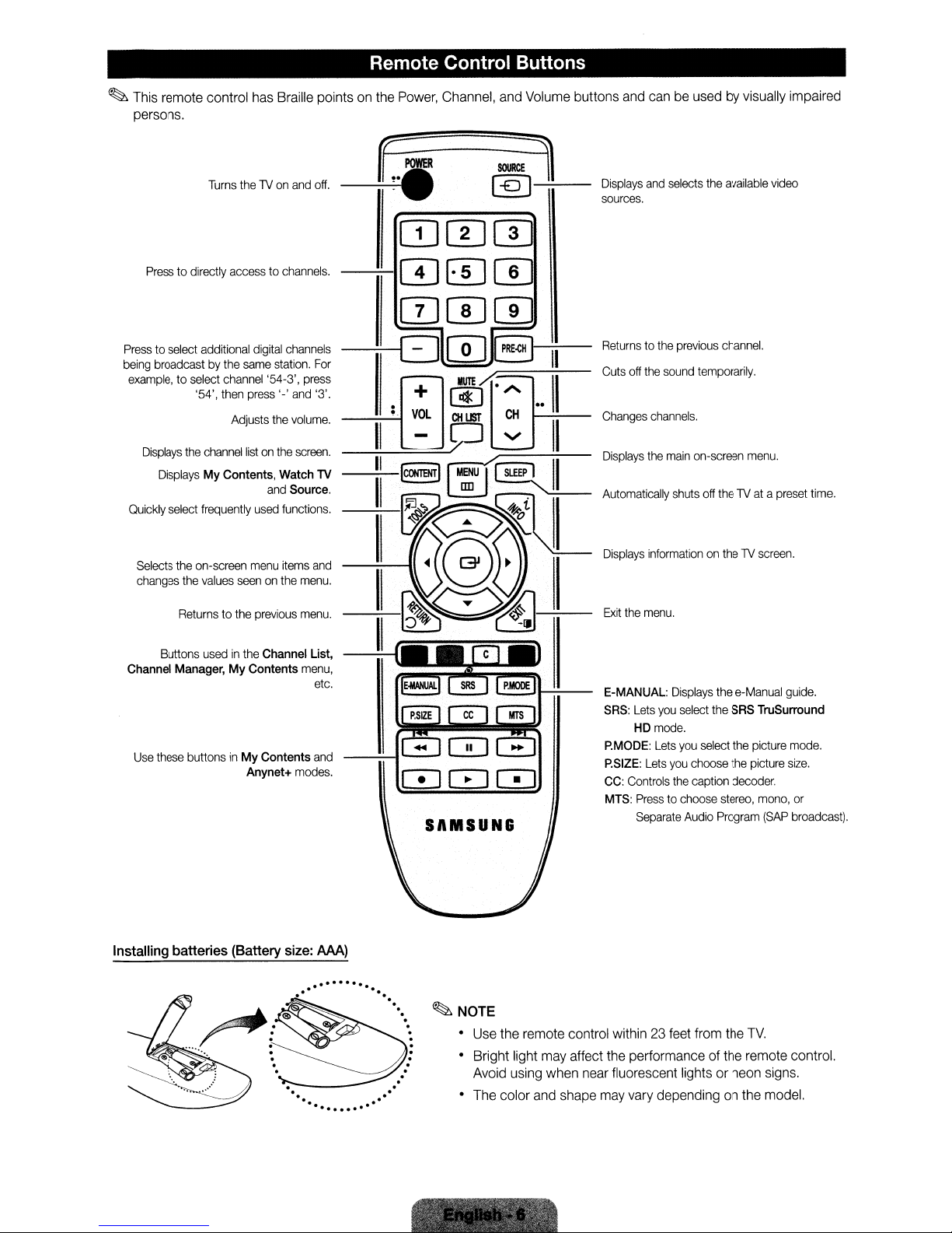
This remote control has Braille points on the Power, Channel, and Volume buttons and can be used by visually impaired
persons,
Displays
and
selects
the
available
video
Press
to directly access to
Turns
thelVon
and
off,
channels.
sources.
Presstoselect
being
example,
Displays
Quickly
Selects
changes
Channel Manager, My Contents
Use
additional
broadcastbythe
to select
channel
'54',
then
Adjusts
the
channel
Displays
My Contents, Watch
select
frequently
the
on-screen
the
values
Returns
to the
Buttons
usedinthe Channel List,
these
buttonsinMy Contents
digital
same
station.
'54-3',
press
'-'
the
listonthe
and
used
menu
seenonthe
previous
Anynet+
channels
For
press
and
'3'.
volume.
screen.
Source.
functions.
items
and
menu.
menu.
menu,
etc.
and
modes.
TV
SAMSUNS
Returnstothe
Cuts
off
Changes
Displays
Automatically
Displays
Exit
the
E-MANUAL:
SRS:
P.MODE:
P.SIZE:
CC:
Controls
MTS:
previous
the
sound
channels.
the
main
shuts
informationonthelVscreen.
menu.
Displays
Lets
you
select
HD
mode.
Lets
you
Lets
you
choose
the
caption
Presstochoose
Separate
Audio
channel.
temporarily.
on-screen
select
menu.
off
thelVatapreset
the
e-Manual
the
SRS
the
the
decoder.
stereo,
Program
guide,
TruSurround
picture
mode.
picture
size.
mono,
or
(SAP
broadcast).
time.
Installing batteries (Battery size:
MA)
...........
..
~:.~
r&':~~"';;.c".:
. .
.
. .
.....
.
.
...
...
.
.
....
.
.
:
.
~NOTE
• Use the remote control within 23 feet from the
Bright light may affect the performance of the remote control.
Avoid using when near fluorescent lights or neon signs.
The color and shape may vary depending on the model.
~,'
.
'"
,'''':
"
~~:~
',',
\
~.~
.
.
TV.
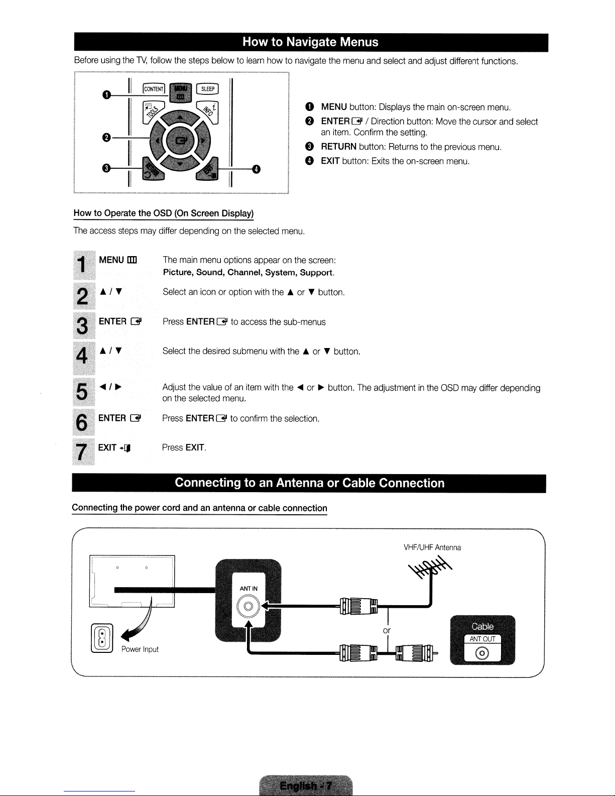
Before
using
o
I e
the
TV,
follow
1I[CoNTENTJ
II
the
steps below to
How to Navigate Menus
learn
howtonavigate
o
f)
e
o
the
menu
MENU
ENTER
an
item.
RETURN
EXIT
button:
and
button:
[3l
/
Confirm
button:
select
Displays
Direction
the
Returnstothe
Exits
the
and
the
button:
setting.
on-screen
adjust
main
Move
different
on-screen
the
previous
menu.
functions.
menu.
cursor
menu.
and
select
L:_II
How to Operate the
The
access
MENU
__
steps
may
lID
~_II:O_
OSD
(On
Screen Display)
differ
dependingonthe
The
main
menu
Picture, Sound, Channel, System, Support.
Selectaniconoroption
Press
Select
Adjust
on
the
Press
Press
ENTER
ENTER
EXIT.
the
desired
the
valueofan
selected
[3l
[3l
options
to
access
submenu
menu.
to
confirm
selected
item
menu.
appearonthe
with
the..or
the
with
with
the
the
sub-menus
the..or
...
or~button.
selection.
screen:
T button.
T button.
The
adjustmentinthe
OSD
may
differ depending
Connecting to
Connecting the power cord andanantenna or cable connection
'-~-~~----------l
. ,
i 1
II
an
Antenna or Cable Connection
I
)
Power
Input
or
VHF/UHF
Antenna
j
~"'.
.:;•'..,
"
"N
I
;:.
~
~
.',.~.
.
.'.
Plug &Play (Initial Setup)
When you turn the1Von for the first time, a sequence of on-screen prompts will assistinconfiguring basic settings.Toturn on
1V,
press the
the
~
Plug & Playisavailable only when the
~
To
return to the previous stepinthe Plug &Play sequence, press the red button on your remote.
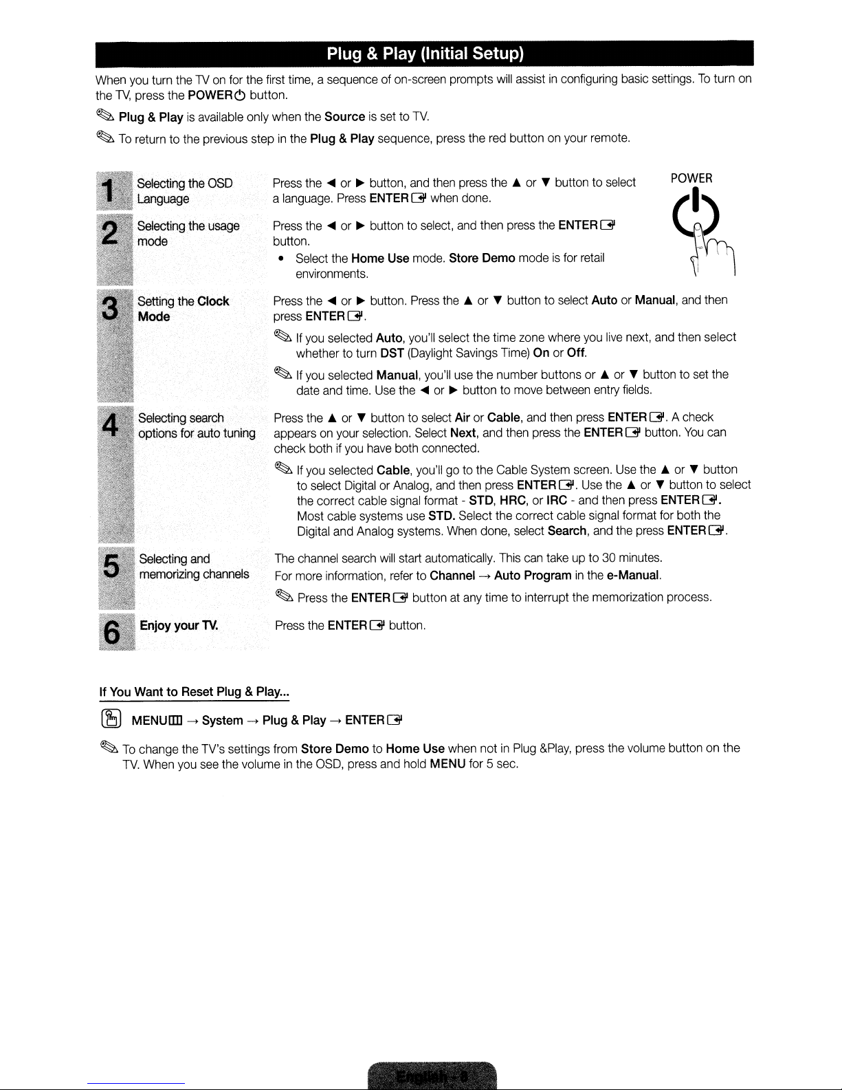
POWERc;
button.
Sourceisset to
TV.
Selecting the OSD
Language
Selecting the usage
mode
Setting the
Clock
Mode
Selecting search
options for auto tuning
Selecting and
memorizing channels
Press the~or~button, and then press
a language. Press ENTER
Press the
button.
• Select the
Press the
press ENTER
~
~
Press the ... or T button to select Air or Cable, and then press ENTER
appears on your selection. Select Next, and then press the ENTER
check both if you have both connected.
~
The channel search will start automatically. This can take up to 30 minutes.
For more information, refer to Channel
~
~or~
environments.
~or~
If
you selected Auto, you'll select the time zone where you
whether to turn DST (Daylight Savings Time) On or Off.
If
you selected Manual, you'll use the number buttons or ...orT button to set the
date and time. Use the
If
you selected Cable, you'll go to the Cable System screen. Use
to select Digital or Analog, and then press ENTER
the correct cable signal format - STD, HRC, or IRC - and then press
Most cable systems use STD. Select the correct cable signal format for both the
Digital and Analog systems. When done, select Search, and the press ENTER
Press the ENTERG'buttonatany time to interrupt the memorization process.
button to select, and then press the ENTER
Home
button. Press
G'.
G'
when done.
Use mode. Store
the'"
~or~
the'"
or T button to select
G'
Demo
modeisfor retail
or T button to select Auto or Manual, and then
live
next, and then select
buttontomove between entry fields.
G'.
G'
button.
the'"
G'.
Use
the'"
or T button to select
ENTERG'.
->
Auto
Programinthe e-Manual.
POWER
~
A check
You
can
or T button
G'.
your
Enjoy
If
You
WanttoReset Plug &Play...
~
MENUIIII->System->Plug &Play->ENTER
~
To
change the TV's settings from
TV.
When you see the volumeinthe OSD, press and hold MENU for 5 sec.
TV.
Press the ENTER
Store
G'
button.
G'
DemotoHome
Use when notinPlug
&Play,
press the volume button on the
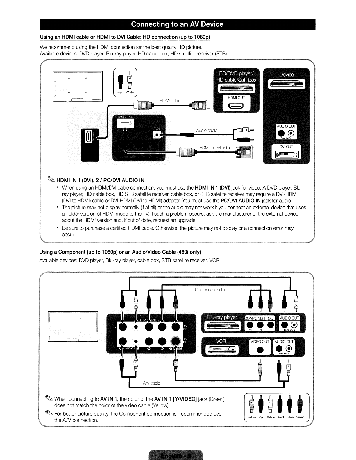
Connecting to an
AV
Device
UsinganHDMI
We
recommend
Available
~
HDMIIN1
•
•
•Besuretopurchaseacertified
cableorHDMItoDVI
using
devices:
When
ray
(OVItoHOMI)
The
an
about
occur.
OVO
(DVI),
usinganHOMIIOVI
player,HOcable
picture
may
older
versionofHOMI
the
HOMI
the
----_._--_
Cable:HDconnection
HOMI
player,
-,
Blu-ray
I
i
connection
Red
for
player,HOcable
White
J
2 I
PC/DVI
cableorOVI-HOMI
not
version
..
_----_._._.-
AUDIO
cable
connection,
box,HOSTB
display
normally
modetothe1VIf
and,ifoutofdate,
HOMI
satellite
(OVItoHOMI)
the
best
qualityHOpicture.
box,HOsatellite
HOMI
IN
you
receiver,
adapter.
(ifatall)orthe
suchaproblem
requestanupgrade.
cable.
Otherwise,
..
_._
..
_
..
-----
cable
must
cable
audio
(upto1
use
the
box,orSTB
You
must
may
occurs,
the
picture
D8Dp)
receiver
HOMItoOVI
HDMIIN 1
satellite
use
the
not
workifyou
ask
may
not
(STB).
cable
(DVI)
jack
for
receiver
PC/DVI
the
AUDIOINjack
connectanexternal
manufacturerofthe
displayora
video.AOVO
may
requireaOVI-HOMI
for
device
external
connection
player,
audio.
error
that
device
may
Blu-
uses
UsingaComponent
Available
devices:
,r-'
I
~
When
connecting toAVIN1,the
does
not
match
~
For
better picture
\.......
theANconnection.
OVO
(upto1
player,
the
colorofthe
quality,
D8Dp)
oranAudioNideo
Blu-ray
player,
cable
AN
coloroftheAVIN
video
cable
the
Component connectionisrecommended
Cable
box,
STB
cable
(Yellow).
(48Di
satellite
1 [YIVIDEOj jack
only)
receiver,
Component
VCR
cable
(Green)
over
tt@ttt
Yellow
Red
White
Red
Blue
Green
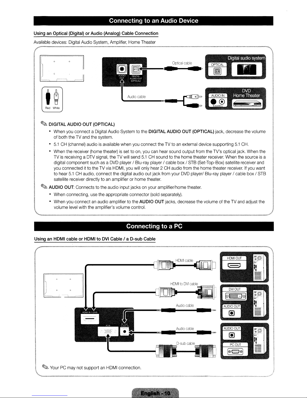
Connecting to an Audio Device
UsinganOptical
Available
devices:
~
(
I i • •
l
I I G •
(
L____
Red
White
~
DIGITAL
•
When
•
•
TVisreceivingaDTV
~
AUDIO
•
•
'--_
(Digital)orAudio
Digital
Audio
'
.-----,
AUDIO
you
of both
5.1CH(channel)
When
the
digital component
you
connecteditto
to
hear
satellite
OUT:
When
connecting,
When
you
volume
..
_
OUT
connect a
theTVand
receiver
5.1CHaudio,
receiver
Connectstothe audio input jacksonyour amplifier/home
connectanaudio
level
with
..
_._-
(Analog)
System,
..
_--
(OPTICAL)
Digital
the
system.
audioisavailable
(home
theater)issettoon,
signal,
suchasa
theTVvia
connect
directly toanamplifierorhome
use
the
appropriate connector
the
amplifier's volume control.
Cable
Amplifier,
Audio
theTVwill
DVD
HDMI,
the
amplifier to the
Home
a
AUDIO
GIJT
AUDIO
t
A_Ud_io_c_a_ble
Systemtothe
when
send
player
you
digital audio out jack
Connection
Theater
OI(,ITAI
OUT
you
connect
/ Blu-ray
will
AUDIO
Optical
c::II."""'l~
DIGITAL
you
can
5.1CHsoundtothe
player
only
hear2CH
theater.
(sold
,~,--_
AUDIO
theTVtoanexternal
hear
sound
/ cable
audio
from
your
separately).
OUT
jacks, decrease
cable
OUT
output
home
box/STB
from
DVD
theater.
Digital
audio
system
OPTICAL
~
-
(OPTICAL)
device supporting
from
theater
(Set-Top-Box)
the home theater
player/ Blu-ray
the
~,._.."""-,---~_._,._
jack, decrease
5.1
the
TV's
optical
jack.
receiver.
volumeoftheTVand
When
satellite
receiver.Ifyou
player
/ cable
the
receiver
the
volume
CH.
When
sourceisa
and
want
box/STB
adjust
the
..
_---,
the
Connecting to a PC
UsinganHDMI
~
J
'----~
I
~
, )
YourPCmay
"-l
cableorHDMItoDVI
_
.•
---'---'------'-.
______
J
not
supportanHDMI
...~'__."",_.",._"
Cable / a
__
D-sub
Cable
Audio
cable
Audio
cable
connection. !
.~__.__
'.
.,.""
..._.__
.,,"__....,...
__
..
_.,..,
...
,""'
......
.,.~.~
..
',._
.......
..,.""''''.,.__,_"
__
.';_,,,.,,~'''
nl
.',
...
__
.",,,,~,,fr
I
I
I
I
I
I
I
I
I
I
~

PC
Display Modes (D-Sub and HDMI/DVI Input)
OptimalPCresolutionis1360 x
column.
The1Vwill
MAC
VESADMT
automatically
640x350
720x400
640x480
832x624
640x480
800x600
1024x768
1360x768
~NOTE
•
For
•
The
•
The
•
Separate
HOMI/OVI
interlace
set
cable connection,
modeisnot
might operate abnormallyifyou
and
Composite modes
768@60Hz.
adjusttothe
you
supported.
are
You
can
also
select
oneofthe
resolution
31.469
31.469
35.000
49.726
31.469
37.861
37.500
37.879
48.077
46.875
48.363
56.476
60.023
47.712
must
use
you
the
HDMIIN1
choose.
select a non-standard video
supported.
SOG
(SyncOnGreen)isnot supported.
70.086
70.087
66.667
74.551
59.940
72.809
75.000
60.317
72.188
75.000
60.004
70.069
75.029
60.015
(DVI)
standard
jack.
format.
resolutions
25.175
28.322
30.240
57.284
25.175
31.500
31.500
40.000
50.000
49.500
65.000
75.000
78.750
85.500
listedinthe
Resolution
+
- / +
-/ -
- / -
-/ -
-
-/ -
+/+
+/+
+/+
-
-
+/+
+/+
/-
/-
//-
EX-LINK
I(!)J Connector
EX-UNK
Changing the Input Source
Source List
Usetoselect1Voranexternal
source
suchasa
player/cable
1.
Press
remote.
2.
Selectadesired
•
TVIPC
I
AV2
IUSB
~
You
can
connectedtothe
be
highlighted.
~
If
you
Connected
~
PC
always
OVO
playerIBlu-ray
box/STB
the
SOURCE
satellite
buttononyour
external
I HDMI1/DVI I HDMI2 I
I Component1 I Component2
only
choose
external
TV.InSource, connected inputs
wanttosee
connected devices
using
the'"
stays
activated.
for
service
input
receiver.
input
source.
devices that
or~button.
only.
AV1
SOURCE
~
are
only,
move
How to use Edit Name
Edit Name
source.Toaccess
Source.
•
~
~
will
~
to
lets
you
associateadevice
Edit
Name,
press
The
following
VCRIDVD
AV
Receiver I Game I Camcorder I
Devices ITVIIPTV
Name
the
your
input
If
you
have
port withanHOMI
to
enter adevice
if
you
have
with
an
HOMItoOVI
Name to enter a
If
you
connectedanAV
port withanHOMItoOVI
under Edit Nametoenter
selections
I Cable
STB
I Satellite
I Blu-rayI
devices
source
connectedtothe
selection
connected aPCto
cable,
selectPCunder
name.
connected aPCto
cable,
device
name.
devicetothe
cable,
easier.
a device
nametoan
the
TOOLS
appear
under
STBIPVR
PCIDVI
HD
DVDIDMA:
input
the
HDMIIN 1
the
HDMIIN 1
select
DVIPCunder Edit
HDMIIN 1
select
name.
input
button
Edit
Name:
STB I
PCIDVI
jackstomake
(DVI)
Edit Name
(DVI)
DVI
Devices
In
port
(DVI)
Information
You
can
see
detailed
information
about
the
selected
external
device.

How
Screen Display
to
view
You
can
use,
press
the
find
instructions
the
e-Manual
for
E-MANUAL
buttononyour
your
TV's
down/right/left buttonstohighlightacategory,
ENTER
You
~
~
~
(31
can
button.
also
The
e-Manual
accessitthrough
the
MENU[[I]~Support~e-Manual~ENTER
To
returntothe
You
cannot
e-Manual
use
Try Now directlyiftheTVis
main
menu,
featuresinthe
remote.
displays
the
menu:
press
the
E-MANUAL buttononthe
settoan
o
Currently
•
The
category
e
Displays
your
button
o I!l
e G Enter:
o
+[J
e-Manualinyour
Move
the
cursor
then
atopic,
page
you
(31
external
displayed
category
remotetomove
Blue
Exit:
list.
you
want.
the
sub-menu
to
select
(Index):
Selectsacategoryorsub-menu.
Exit
the
and
wanttosee.
input
source.
video,TVprogram,
Press
<Ill
list.
the
cursor.
the
sub-menu
Displays
the
e-Manual.
TV.
To
using
the
up/
then
press
the
remote.
etc.
or~buttontoselect
Use
the
arrow
buttons
Press
the
ENTER
you
want.
index
screen.
the
on
G
How to toggle between
•
~~~I,~;,~:~/T",,(GIIll
po'••
'~
• ,"..,,,,
•
1.Ifyou
2.
wanttouse
e-Manual
To
returntothe
button.
topic,
press
e-Manual
an
e-Manual topic and the corresponding
••.
~.<'...-.,.."__'C<>n~
............
""""0T...
,,,,,,,,..,.c.,IJ""~"""_'~'oo,~,,,
;'';...::~'~'':':;;';'"''OV"'''''-'''''~',C'''''''''
the
menu
the
...
that correspondstoan
red
buttontoselect
screen,
c===:=.-
•
(E.MANUAL)~====:J
Try
Now.
press
c
the
E-MANUAL
1.
2.
OSD
menu(s).
Press
the
ENTER
"Do
you want to execute this?"
and
then
press
the
appears.
To
returntothe
button.
a-Manual
G button
ENTERGbutton.
when
screen,
a topicisdisplayed.
appears.
press
Select
The
the
Yes,
OSD
window
E-MANUAL
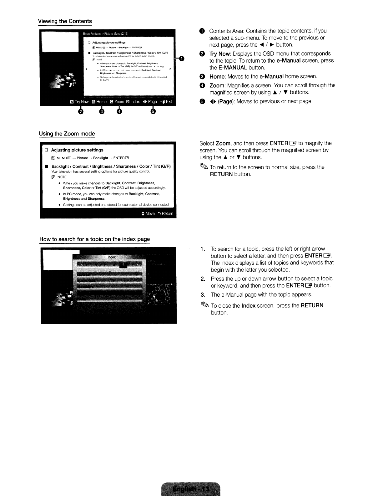
Viewing the Contents
Using the Zoom mode
o Adjusting
I!ll
• BacklightI Contrast I Brightness I Sharpness I Color I Tint
Your
® NOTE
picture
settings
MENU!ID -
Picture-Backlight
television
has
several
setting options
• When you make changes to
Sharpness,
•InPC
Brightness
• settings
Color
mode,
you
and Sharpness.
canbeadjusted
or Tint
can
- ENTER
01'
for
picture quality control.
Backlight,
the OSD
stored
for
Contrast. Brightness.
will
be adjusted accordingly.
each
external
~
(G1R)
only
make changes to Backlight, Contrast,
and
(GIRl
device
connected
Move~Return
o
Contents
Area:
Contains
the
selectedasub-menu.Tomovetothe
next
page,
press
the
....
/~button.
f)
Try
Now:
to
the
topic.Toreturntothe
the
E-MANUAL
e Home:
o Zoom:
magnified
e
~~
(Page):
Select
Zoom,
screen.
You
using
the~or"buttons.
~
To
returntothe
RETURN
Displays
Movestothe
Magnifiesascreen.
screenbyusing~/ " buttons.
and
can
button.
the
OSD
button.
e-Manual
Movestopreviousornext
then
press
ENTER
scroll
through
screentonormal
topic
menu
e-Manual
home
You
can
the
magnified
contents,ifyou
previous
that
corresponds
screen,
screen.
scroll
through
page.
G to
magnify
screen
size,
press
the
or
press
the
the
by
How to search for a topic on the index page
To
search
1.
foratopic,
buttontoselectaletter,
The
Index
displaysalistoftopics
begin
with
the
2.
Press
theupor
or
keyword,
3.
The
e-Manual
~
To
close
the
button.
letter
and
page
Index
down
then
press
and
you
selected.
arrow
press
with
the
screen,
the
leftorright
then
press
and
button to
the
ENTERG
topic
appears.
press the
arrow
ENTER
keywords
select
atopic
button.
RETURN
G.
that
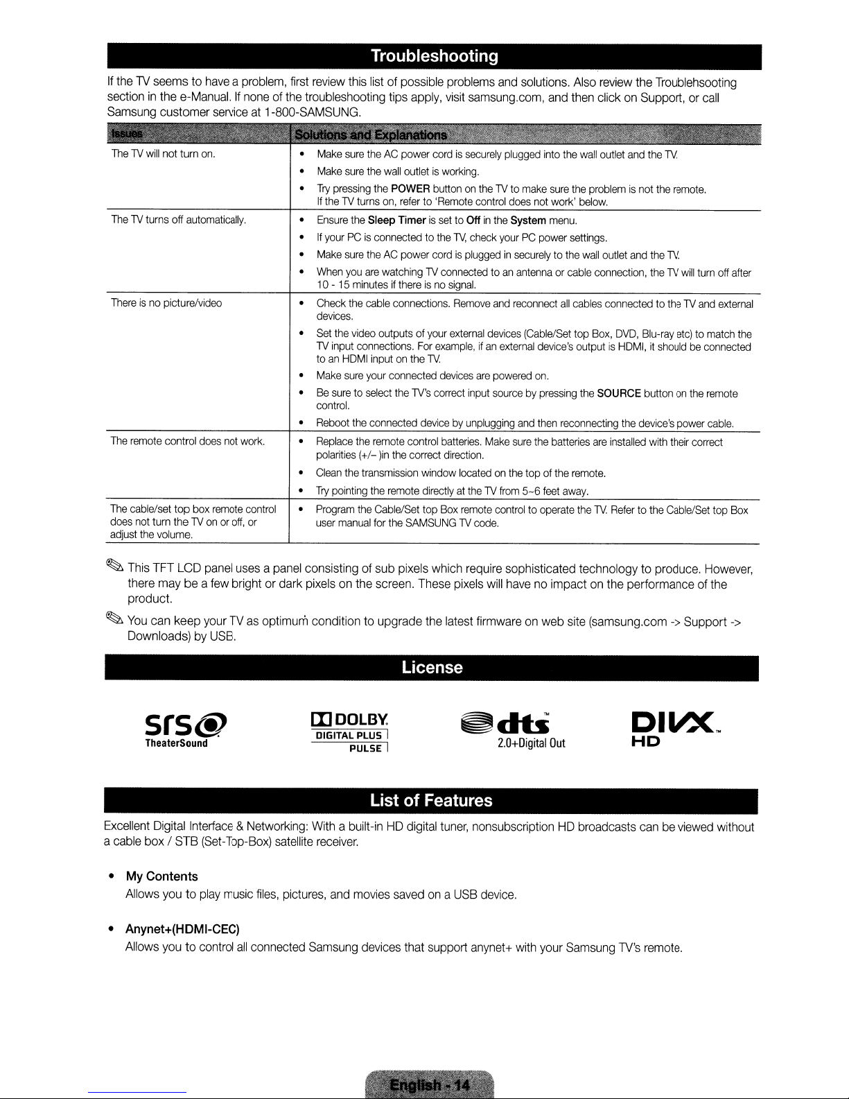
If
the1Vseemstohaveaproblem,
sectioninthe
Samsung
e-Manual.Ifnoneofthe
customer
serviceat1-800-SAMSUNG.
first
review
this
troubleshooting tips
Troubleshooting
listofpossible
apply,
problems
visit
samsung.com,
and
solutions.
and
Also
review
the
Troublehsooting
then
clickonSupport,orcall
ThelVwill
ThelVturns
Thereisno
The
remote
The
cable/set top
does
not
adjust
turn thelVonoroff,
the
not
turn
off
automatically.
picture/video
control
box
volume.
on.
does
not
remote
work.
control
or
Make
sure
Make
sure
•
Try
pressing
If
thelVturns
•
Ensure
the
•IfyourPCis
•
Make
sure
When
•
•
•
•
•
•
•
you
10-15
minutesifthereisno
Check
the
devices.
Set
the
video
lV
input
connections.
toanHOMI
Make
sure
Be
suretoselect
control.
Reboot
the
Replace
the
polarities
Clean
Try
Program
user
(+/-
the
pointing
the
manual
theACpower
the
wall
the
on,
Sleep TimerissettoOffinthe
connectedtothe
theACpower
are
watchinglVconnectedtoan
cable
outputs of
inputonthe
your
connected
connected
remote
lin
transmission
the
remote
Cable/Set
for
the
cordissecurely
outletisworking.
POWER
buttononthelVto
referto'Remote
cordispluggedinsecurelytothe
connections.
your
For
lV.
the
lV's
devicebyunplugging
control
the
correct
window
directlyatthelVfrom
top
SAMSUNGlVcode.
control
1\1,
check
signal.
Remove
external
example,ifan
devices
are
correct
input
batteries.
direction.
locatedonthe
Box
remote
plugged
into
make
sure
does
not
work'
System
menu.
yourPCpower
antennaorcable
and
reconnect
devices
(Cable/Set
external
device's
powered
sourcebypressing
Make
on.
and
then
sure
the
top of
5-6
feet
controltooperate
the
wall
outlet
and
the
lV.
the
problemisnot
below.
settings.
wall
outlet
connection,
all
cables
connectedtothelVand
top
Box,
outputisHOMI,itshouldbeconnected
the
SOURCE
reconnecting
batteries
are
installed
the
remote.
away.
the
lV.
Refertothe
and
OVO,
the
the
remote.
the
lV.
thelVwill
Blu-ray
etc)tomatch
buttononthe
device's
power
with
their
Cable/Set
turn
remote
cable.
correct
off
after
external
top
Box
the
~
This
TFT
LCD
panel
there
maybea
few
product.
~
You
can
keep
yourTVas
Downloads)byUSB.
srs@
TheaterSound
Excellent
a
•
• Anynet+(HDMI-CEC)
cable
My
Allows
Allows
Digital
box/STB
Contents
youtoplay
youtocontrol
Interface&Networking:
(Set-Tap-Box)
usesapanel
brightordark
consistingofsub pixels
pixelsonthe
optimum conditiontoupgrade
mOOlBy.
DIGITAL PLUS I
Withabuilt-inHDdigital
music
all
satellite
files,
connected
pictures,
Samsung
receiver.
and
screen.
PULSE I
List
movies
devices
which
These
pixels
the
latest
License
~db
of Features
tuner,
savedona
that
USB
support
require
sophisticated technology to produce.
will
havenoimpactonthe
firmwareonweb
2.0+Digital
site
(samsung.com->Support
Out
nonsubscriptionHDbroadcasts
device.
anynet+
with
your
Samsung
performanceofthe
canbeviewed
1V's
remote.
However,
->
without
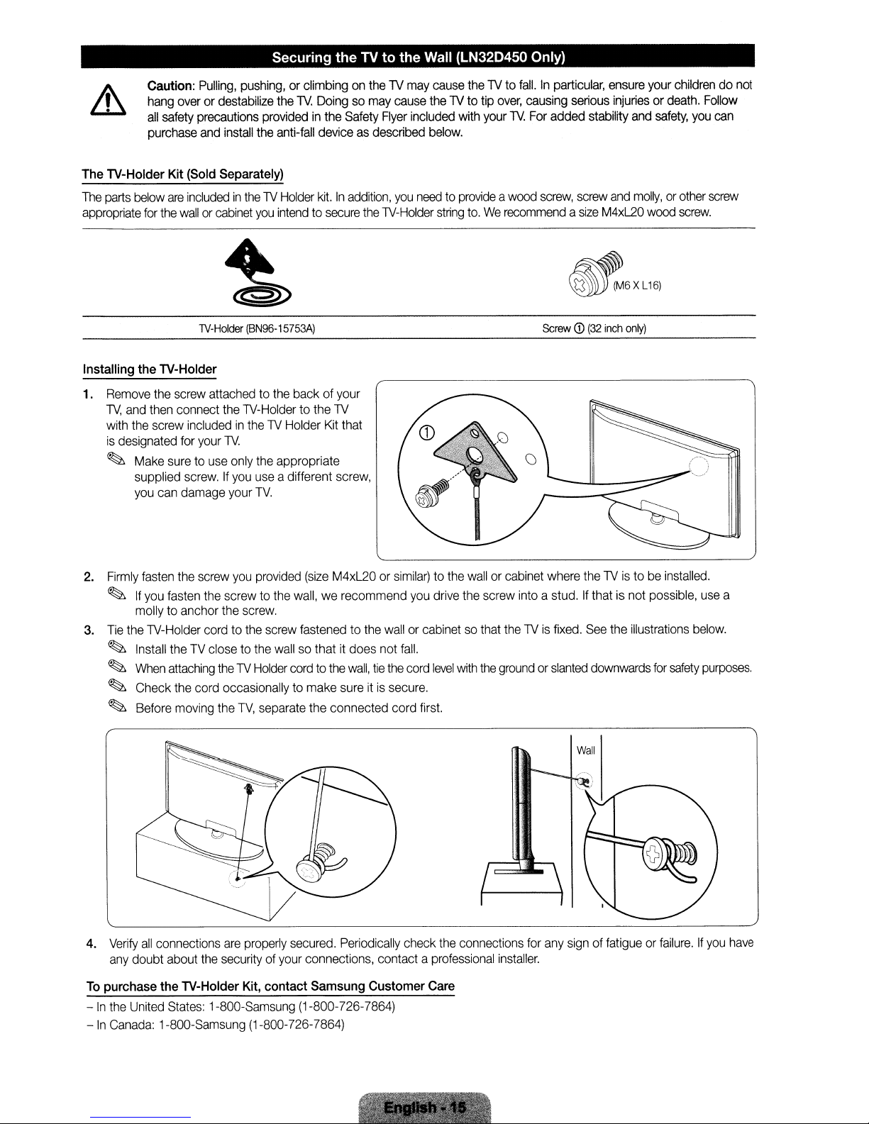
Securing
theTVto
the Wall (LN32D450 Only)
Caution:
hang
all
purchase
The lV-Holder Kit (Sold Separately)
The
parts
below
appropriate
Installing the lV-Holder
1.
Remove
TV,
and
with
the
is
designated
~
Make
supplied
you
for
the
then
screw
can
Pulling,
pushing,
overordestabilize
safety
precautions
and
install
are
includedinthelVHolder
the
wallorcabinet
lV-Holder
screw
attachedtothe
connect
includedinthelVHolder
for
your
suretouse
screw.Ifyou
damage your
you
(BN96-15753A)
the
lV-Holder to
lV.
only
the
use
TV.
providedinthe
the
or climbingonthelVmay
the
lV.
Doingsomay
Safety
Flyer
anti-fall
deviceasdescribed
kit.Inaddition,
intendtosecure
back of
the
appropriate
a different
lV
Kit
screw,
your
that
the
lV-Holder
cause
thelVto
cause
thelVto tip
included
you
with
below.
needtoprovideawood
string
to.Werecommendasize
fall.Inparticular,
over,
your
lV.
causing
For
added stability
screw,
Screw
ensure
your
childrendonot
serious
injuriesordeath.
screw
and
M4xL20
and
safety,
molly,orother
wood
you
screw.
Follow
can
screw
~6XL16:
CD
(32
inch
only)
2.
Firmly
fasten
the
screw
you
provided
~
If
you
fasten
the
screw to
molly
to anchor
3.
Tie
the
lV-Holder
~
Install
theTVclosetothe
~
When
attaching
~
Check
the
~
Before
moving
4.
Verify
all
connections
any
doubt about
To
purchase the lV-Holder Kit, contact Samsung Customer Care
-Inthe
United
States:
-
In
Canada:
1-800-Samsung (1-800-726-7864)
the
screw.
cordtothe
thelVHolder
cord occasionallytomake
the
TV,
separate the connected cord
are
properly
the
securityofyour
1-800-Samsung (1-800-726-7864)
(size
M4xL20orsimilar)tothe
the
wall,werecommend
screw
fastenedtothe
wallsothatitdoes not
cordtothe
secured.
connections, contact a
wall,
sureitis
Periodically
wallorcabinetsothat
fall.
tie
the
secure.
you
cord
first.
check
wallorcabinet
drive
the
screw into a stud.Ifthatisnot possible,
level
with
the
the
connections
professional
where
thelVis
groundorslanted
installer.
fixed.
for
any
signoffatigueorfailure.Ifyou
thelVistobe
See
the
illustrations
downwards
Wall
installed.
for
safety
use
a
below.
purposes.
have
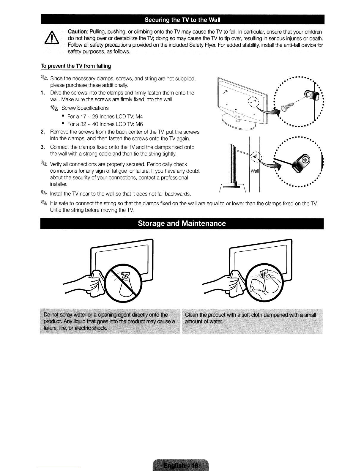
Securing
theTVto
the
Wall
Caution:
do
Follow
safety
To
prevent theTVfrom falling
~
Since
the
please
purchase
1.
Drive
the
screws
wall.
Make
~
Screw
•
Fora17-29
•
Fora32-40
2.
Remove
into
3.
Connect
the
~
Verify
connections
about
installer.
~
Install
~
Itissafetoconnect
Untie
the
the
clamps,
the
wall
withastrong
all
connections
the
the1Vneartothe
the
string
Pulling,
not
hang
all
safety
purposes,asfollows.
necessary
these
into
sure
the
Specifications
screws
and
clamps
for
any
securityofyour
before
pushing,orclimbing
overordestabilize
precautions
clamps,
the
screws
from
then
fixed
are
signoffatigue
the
screws,
additionally.
clamps
and
are
firmly
Inches
LCD
1V:
Inches
LCD
1V:
the
back
centerofthe
fasten
the
onto
the1Vand
cable
and
then
properly
connections,
wallsothatitdoes
stringsothat
moving
the
secured.
for
1V.
onto
the1Vmay
the
1V;
doingsomay
providedonthe
and
string
firmly
fasten
fixed
into
M4
M6
screws
onto
the
tie
the
string
Periodically
failure.Ifyou
contactaprofessional
not
the
clamps
included
are
not
them
the
wall.
1V,
put
the1Vagain.
clamps
tightly.
have
fall
backwards.
fixedonthe
supplied,
onto
the
screws
fixed
check
any
cause
Safety
the
onto
doubt
wall
cause
are
the
1Vto
the1Vto
Flyer.
For
equaltoor
fall.Inparticular,
tip
over,
resultinginserious
added
stability,
lower
than
the
ensure
install
clamps
that
your
injuriesordeath.
the
anti-fall
........
....
.
.
..•..•....
.
.
.
fixedonthe
children
device
.n
1V.
for
.
.
.
.
·
·
·
·
.
·
•
.
.
Storage and Maintenance
Di
Ia
Resolution
Environmental
Considerations
Operating
Operating
Storage
Storage
Stand
(LeftIRight)
Screen
(Diagonal)
Sound
Output
Dimensions
Temperature
Humidity
Temperature
Humidity
Swivel
Size
(WxDxH)
(26.0"
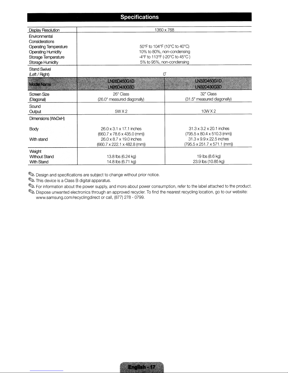
Specifications
26"
Class
measured
diagonally)
5WX2
1360x
50°Fto104°F
10%to80%,
-4°Fto113°F
5%to95%,
768
(10°Cto40°C)
non-condensing
(-20°Cto45°C)
non-condensing
(31.5"
32"
Class
measured
10WX2
diagonally)
Body
With
stand
Weight
Without
WithStand
~
~
~
~
Stand
Design
and
specifications
This
deviceisa
For
information about
Dispose unwanted electronics throughanapproved
www.samsung.com/recyclingdirect or
Class
are
B digital apparatus.
the
power
26.0x3,1 x
(660.7x78.6x435,0
26.0x8.7x19.0
(660.7x222.1x482.8
13.8
14.81bs
subject to change without prior notice.
supply,
and
call,
17.1
inches
(mm))
inches
(mm))
Ibs
(6.24
kg)
(6.71
kg)
more
about power consumption,
recycler.Tofind
(877)
278-0799
.
31.3x3.2x20.1
(795.5
x
8004
31.3x9.9x22.5
(795.5x251.7x571.1
19
Ibs
23.9
Ibs
refertothe
the
nearest recycling location,goto
label
inches
x
510.3
(mm))
inches
(mm))
(8.6
kg)
(10.85
kg)
attachedtothe
our website:
product.
.•
~~~:i'.,-'1'_
C"','
.;:'\
':'~';"~:'Iz:':
~
'.
"
~
~"
.

Dimensions
•
Front
view!
side
view
1-0--.1
(Unit:
inches)
LN26D450G1D
LN26D430G3D
LN32D450G1
LN32D430G3D
•
Jack
panel
LN26D450G1D
LN26D430G3D
LN32D450G1
LN32D430G3D
D
detail!
D
26.0
31.3
rear
view
~m
I.@
••••
I.@
••••
~~I
8
10.2
22.7
27.5
@)
2.4
2.6
12.7
15.5
4.3
5.1
17.2
19.8
17.1
20.1
17.0
22.1
19.0
22.5
7.8
7.8
3.1
3.2
(Unit:
8.7
9.9
inches)
39
7.8
NOTE:
All
drawings
dimensions
©
2011
priortoperforming
Samsung
are
not
Electronics
necessarilytoscale.
installationofyour
America,
Inc
Some
TV.
dimensions
Not
responsible
are
subject to
for
typographicalorprinted
change
without
prior
errors.
notice.
Refertothe
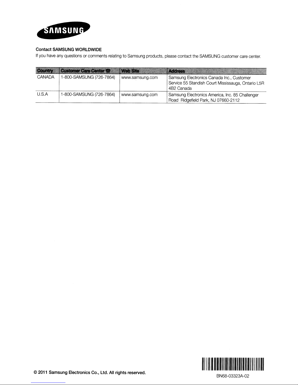
Contact
If
you
have
SAMSUNG
any
WORLDWIDE
questionsorcomments
relatingtoSamsung
products,
please
contact
the
SAMSUNG
customer
care
center.
CANADA
U.S.A
1-800-SAMSUNG
1-800-SAMSUNG
(726-7864)
(726-7864)
www.samsung.com
www.samsung.com
Sam
sung
Electronics
Service55Standish
4B2
Canada
Samsung
Road
Electronics
Ridgefield
Park,NJ07660-2112
Canada
Court
America,
Inc.,
Customer
Mississauga,
Inc.85Challenger
Ontario
L5R
©
2011
Samsung
Electronics
Co.,
Ltd.
All
rights
reserved.
1111111111111111I1111I1111111111111
BN68-03323A-02
11111111
• Assemble Stand before removing TV
•
Components
f.I
i'
1
EA
When
installing
the
stand,
from
use
the
shipping
provided
components
box
and
parts.
Stand
o
•..........
---'---g~
(dependingonthe
model)
ATIENTION
@@~!
DO
NOT
USEDONOT
CHEMICALS
, ,
..
, ,
, ,
'
. , ,
,,'
,
~U-....AIt'>l'-~':"
GREASE
...................
"
USEDONOT
----_
Guide
~
Stand
x8(M4XL16)
Screws
.~X4"\
Top
(M4
X L16)
I
USE
I
all
I
I
..
-
"t'
T, :
:,
! : : :
: : : :
I
View
~
Place
a soft cloth
~
Insert
the
Caution
over
the
tabletoprotect
Stand
Guide
into
the
slotofTV
~
..
'
M~keslJretodistin9uish
,T
:
j~
I I
~~:
~:~
the
TV,
and
then
place
theTVon
bottom
side.
betW81enl:~1
......
""/
r:
:
(!)
.................. '
the
cloth
............
.'
~X4
(M4
XL16)
Side
~
..
Ir~=~====3.
j
~)'~--·-----i
: : :
'_
screen
side
down.
View
'
BN68-03392A-02
1111111111111111111111111111111111111111111
BN68-03392A-02

1-800-SAMSUNG (7267864)
Samsung Electronics America, Inc.
105 Challenger Road Ridgefield Park, NJ 07660-0511
Samsung Electronics Canada Inc., Customer Service
55 Standish Court Mississauga, Ontario L5R 4B2
Call center hours of operation (Mon-Sun 9AM-12AM EST).
To register this product please visit
www.samsung.com/global/register.
LN26A450C1D/LN32A450C1D/
LN37A450C1D/LN40A450C1D
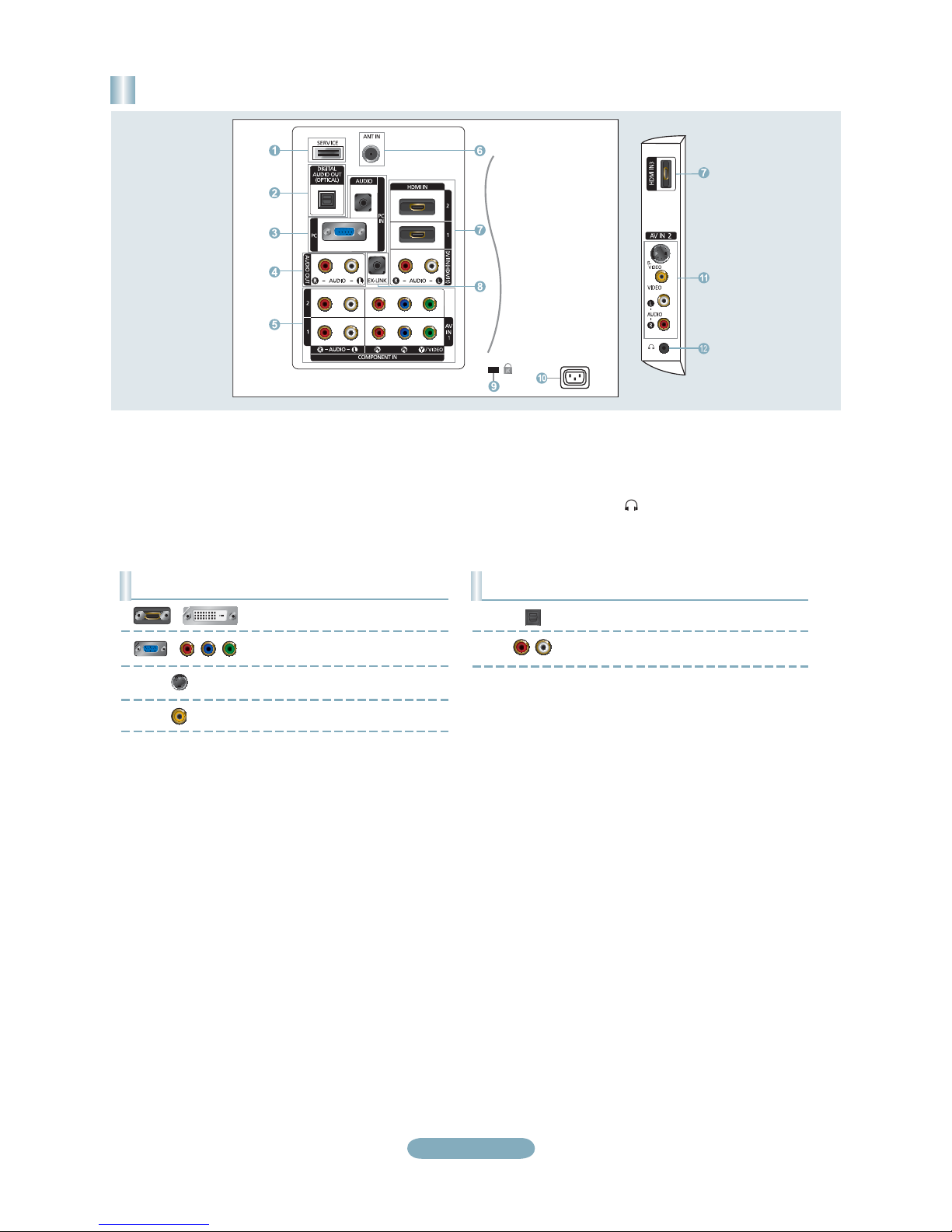
Rear Panel / Side Panel Jacks
1 AUDIO OUT
2 DIGITAL AUDIO OUT (OPTICAL)
3 PC IN [PC] / [AUDIO]
4 HDMI IN 1, 2, 3 / DVI IN (HDMI2)
[R-AUDIO-L]
5 ANT IN
6 AV IN 2
7 HEADPHONE
8 POWER INPUT
(LN26A450C1D, LN40A450C1D)
9 SERVICE
0 COMPONENT IN 1, 2 / AV IN 1
! EX-LINK
@ KENSINGTON LOCK
English-1
Rear Panel / Side Panel Jacks
(LN32A450C1D, LN37A450C1D)
1 SERVICE
2 DIGITAL AUDIO OUT (OPTICAL)
3 PC IN [PC] / [AUDIO]
4 AUDIO OUT
5 COMPONENT IN 1, 2 / AV IN 1
6 ANT IN
7 HDMI IN 1, 2, 3 / DVI IN (HDMI1)
[R-AUDIO-L]
8 EX-LINK
Video Input Performance Comparison
/
/
HDMI/DVI
PC/COMPONENT
S-VIDEO
VIDEO
Best
Better
Good
Normal
9 KENSINGTON LOCK
0 POWER INPUT
! AV IN 2
@ HEADPHONE
Audio Output Performance Comparison
OPTICAL (Digital)
AUDIO (Analog)
Best
Normal
English-2
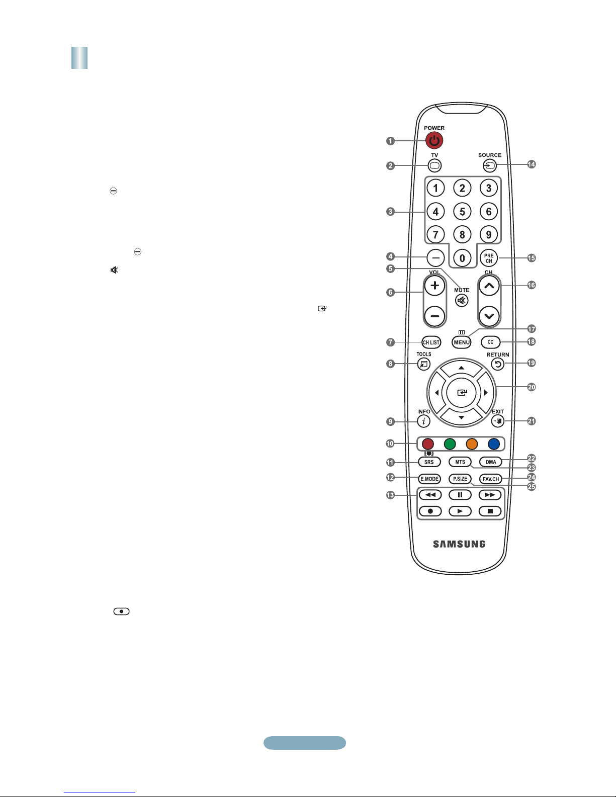
Remote Control
See “Remote Control” in the owner’s instructions for details.
1
POWER
Turns the TV on and off.
2
TV
Selects the TV mode directly.
3
NUMERIC BUTTONS
Press to change the channel.
4
Press to select additional
channels (digital and analog)
being broadcast by the same
station. For example, to select
channel “54-3”, press “54”, then
press “
5
(MUTE)
Press to temporarily cut off the
sound.
6
VOL- / VOL+
Press to increase or decrease
the volume.
7
CH LIST
Used to display Channel Lists
on the screen.
8
TOOLS
Use to quickly select frequently
used functions.
9
INFO
Press to display information on
the TV screen.
0
COLOR BUTTONS
Use these buttons in the
Channel list, etc.
!
SRS
Selects SRS TruSurround XT
mode.
@
E.MODE
Press to select the preset
display and sound modes for
sports, cinema and games.
#
Use these buttons in the DMA
and Anynet+ modes.
(
used to control recording on
Samsung recorders with the
Anynet+ feature)
” and “3”.
: This remote can be
$
SOURCE
Press to display and select the
available video sources.
%
PRE-CH
Tunes to the previous channel.
^
CH> / CH<
Press to change channels.
&
MENU
Displays the main on-screen
menu.
*
CC
Controls the caption decoder.
(
RETURN
Returns to the previous menu.
)
UP / DOWN / LEFT /
RIGHT / ENTER
Use to select on-screen menu
items and change menu values.
a
EXIT
Press to exit the menu.
b
DMA (Digital Media Adapter)
Use this when connecting
a SAMSUNG DMA device
through an HDMI interface and
switching to DMA mode.
For more information on the
operating procedures, refer to
the user manual of the DMA.
This button is available when
"Anynet+(HDMI-CEC)" is "On".
c
MTS
Press to choose stereo, mono
or Separate Audio Program
(SAP broadcast).
d
FAV.CH
Press to switch to your favorite
channels.
e
P.SIZE
Picture size selection.
English-3
Connections (LN26A450C1D, LN40A450C1D)
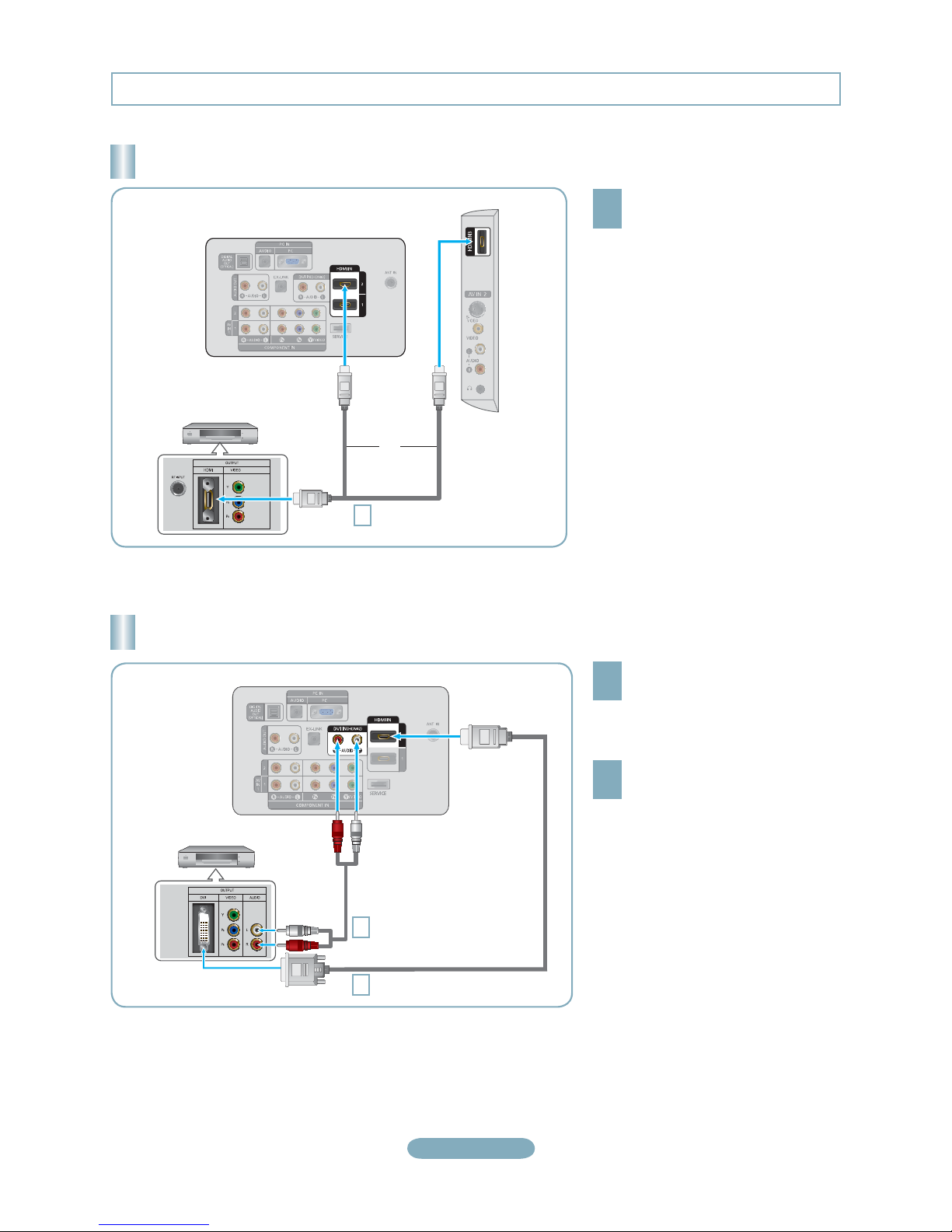
Connecting a DVD Player or Cable Box/Satellite receiver (Set-Top Box) via HDMI
Connect an HDMI Cable between
the HDMI IN (1, 2 or 3) jack on
1
the TV and the HDMI jack on the
DVD Player or Cable Box/Satellite
receiver (Set-Top Box).
What is HDMI?
•
HDMI(High-Definition Multimedia
Interface), is an interface that enables the
transmission of digital audio and video
signals using a single cable.
•
The difference between HDMI and DVI
is that the HDMI device is smaller in
size and has the HDCP (High Bandwidth
Digital Copy Protection) coding feature
installed.
DVD Player or Cable Box/
Satellite receiver (Set-Top Box)
TV Rear Panel
or
HDMI Cable (Not supplied)
1
TV Side Panel
Each DVD Player or Cable Box/Satellite receiver (Set-Top Box) has a different back panel configuration.
°
Connecting a DVD Player or Cable Box/Satellite receiver (Set-Top Box) via DVI
Connect a DVI to HDMI Cable or
DVI-HDMI Adapter between the
1
HDMI IN 2 jack on the TV and the DVI
jack on the DVD Player or Cable Box/
Satellite receiver (Set-Top Box).
Connect Audio Cables between the
DVI IN (HDMI 2) [R-AUDIO-L] jack on
2
the TV and the DVD Player or Cable
Box/Satellite receiver (Set-Top Box).
DVD Player or Cable Box/
Satellite receiver (Set-Top Box)
TV Rear Panel
Audio Cable (Not supplied)
2
DVI to HDMI Cable (Not supplied)
1
Each DVD Player or Cable Box/Satellite receiver (Set-Top Box) has a different back panel configuration.
°
When connecting a DVD Player or Cable Box/Satellite receiver (Set-Top Box), match the color of the connection terminal to the
°
cable.
When using an HDMI/DVI cable connection, you must use the HDMI IN 2 jack.
°
English-4
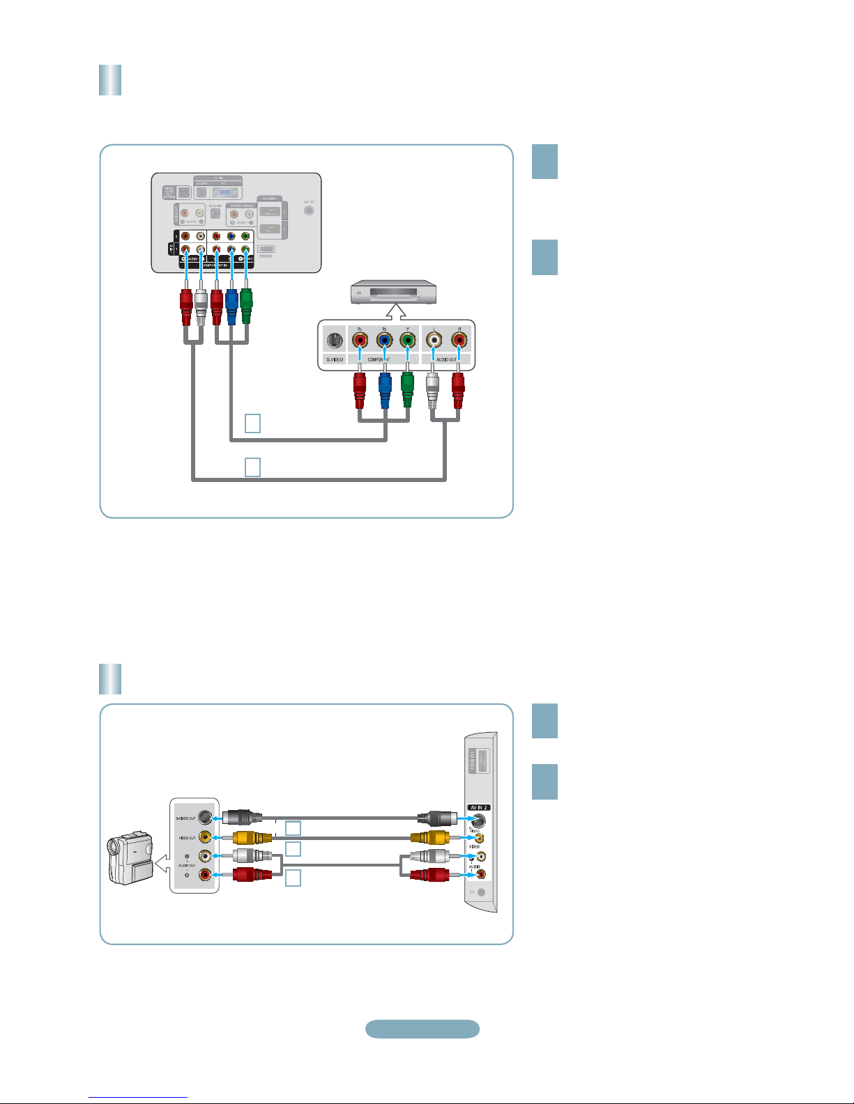
Connecting a DVD Player or Cable Box/Satellite receiver (Set-Top Box)
via Component cables
TV Rear Panel
1
2
DVD Player or Cable Box /
Satellite receiver (Set-Top Box)
Component Cable
(Not supplied)
Audio Cable (Not supplied)
Connect a Component Cable between
the COMPONENT IN (1 or 2)
1
[Y, P
B
, PR] jacks on the TV and the
COMPONENT [Y, P
the DVD Player or Cable Box/Satellite
receiver (Set-Top Box).
Connect Audio Cables between the
COMPONENT IN(1 or 2) [R-AUDIO-L]
2
jacks on the TV and the AUDIO OUT
jacks on the DVD Player or Cable
Box/Satellite receiver (Set-Top Box).
Component video separates the video
°
into Y (Luminance (brightness)), Pb
(Blue) and Pr (Red) for enhanced video
quality.
Be sure to match the component video
and audio connections.
For example, if connecting
a Component video cable to
COMPONENT IN 1, connect the audio
cable to COMPONENT IN 1 also.
Each DVD Player or Cable Box/
°
Satellite receiver (Set-Top Box) has a
different back panel configuration.
When connecting a DVD Player or
°
Cable Box/Satellite receiver (Set-Top
Box), match the color of the connection
terminal to the cable.
B
, PR] jacks on
Connecting a Camcorder
Camcoder
or
S-Video cable (Not supplied)
1
Video cable (Not supplied)
1
Audio cable
2
(Not supplied)
English-5
TV Side Panel
Connect a Video Cable (or S-Video
Cable) between the AV IN 2 [VIDEO]
1
(or S-VIDEO) jack on the TV and the
VIDEO OUT jack on the camcorder.
Connect Audio Cables between the
AV IN 2 [R-AUDIO-L] jacks on the
2
TV and the AUDIO OUT jacks on the
camcorder.
Each Camcorder has a different back
°
panel configuration.
When connecting a Camcorder, match
°
the color of the connection terminal to
the cable.
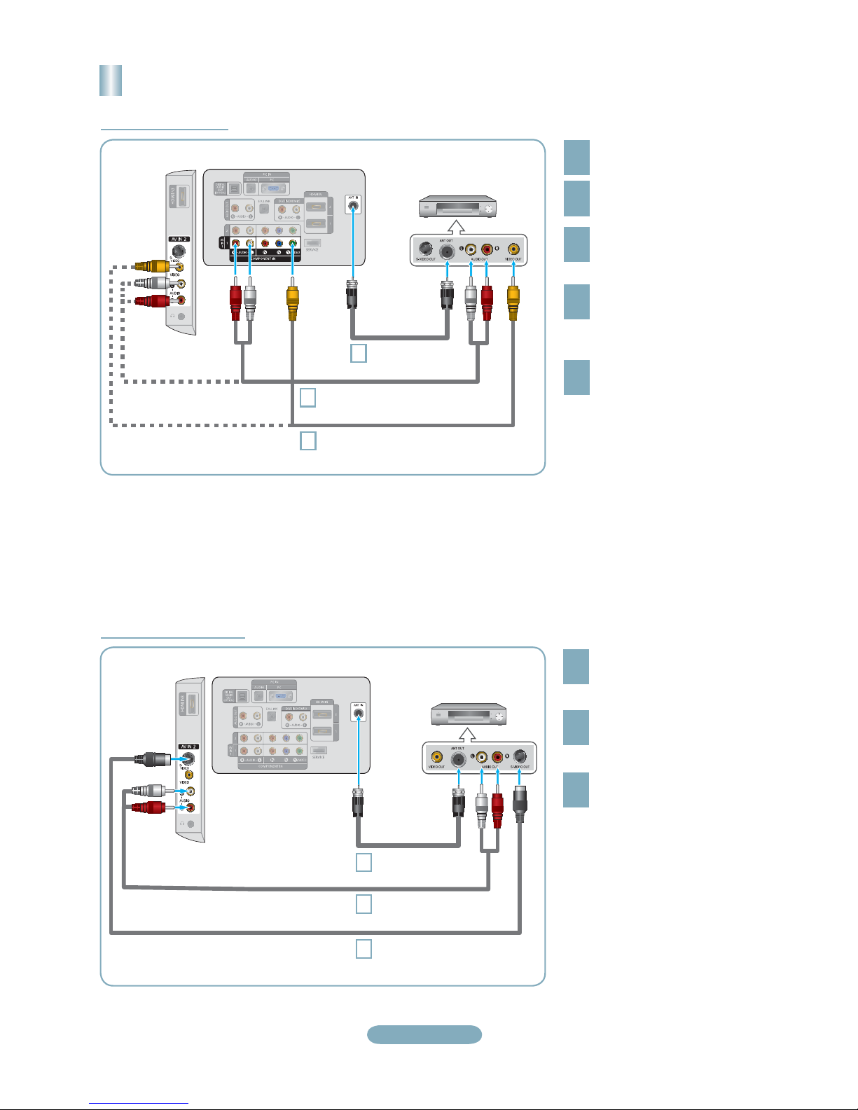
Connecting a VCR
Video Connection
TV Side Panel
Follow the instructions in “Viewing a VCR or Camcorder Tape” to view your VCR tape.
Each VCR has a different back panel configuration.
°
When connecting a VCR, match the color of the connection terminal to the cable.
°
When connecting to AV IN 1, the color of the AV IN 1 [Y/VIDEO] jack (Green) does not match the color of the video cable
°
(Yellow).
TV Rear Panel
RF Cable
3
Audio Cable (Not supplied)
5
Video Cable (Not supplied)
4
VCR Rear Panel
(Not supplied)
Unplug the cable or antenna
from the back of the TV.
1
Connect the cable or antenna
to the ANT IN terminal on the
2
back of the VCR.
Connect an RF Cable between
the ANT OUT terminal on the
3
VCR and the ANT IN terminal
on the TV.
Connect a Video Cable
between the VIDEO OUT jack
4
on the VCR and the AV IN 1
[Y/VIDEO] or AV IN 2 [VIDEO]
jack on the TV.
Connect Audio Cables between
the AUDIO OUT jacks on the
5
VCR and the AV IN 1 (or AV IN 2)
[R-AUDIO-L] jacks on the TV.
If you have a “mono” (non-stereo)
°
VCR, use a Y-connector (not
supplied) to hook up to the right
and left audio input jacks of the
TV. If your VCR is stereo, you
must connect two cables.
S-Video Connection
TV Side Panel
TV Rear Panel
VCR Rear Panel
RF Cable
1
2
3
(Not supplied)
Audio Cable (Not supplied)
S-Video Cable (Not supplied)
To begin, follow steps 1–3 in
the previous section to connect
1
the antenna or cable to your
VCR and your TV.
Connect Audio Cables between
the AUDIO OUT jacks on the
2
VCR and the AV IN 2
[R-AUDIO-L] jacks on the TV.
Connect an S-Video Cable
between the S-VIDEO OUT jack
3
on the VCR and the AV IN 2
[S-VIDEO] jack on the TV.
An S-Video cable may be included
with a VCR. (If not, check your local
electronics store.)
°
Each VCR has a different back
panel configuration.
°
When connecting a VCR, match
the color of the connection
terminal to the cable.
English-6
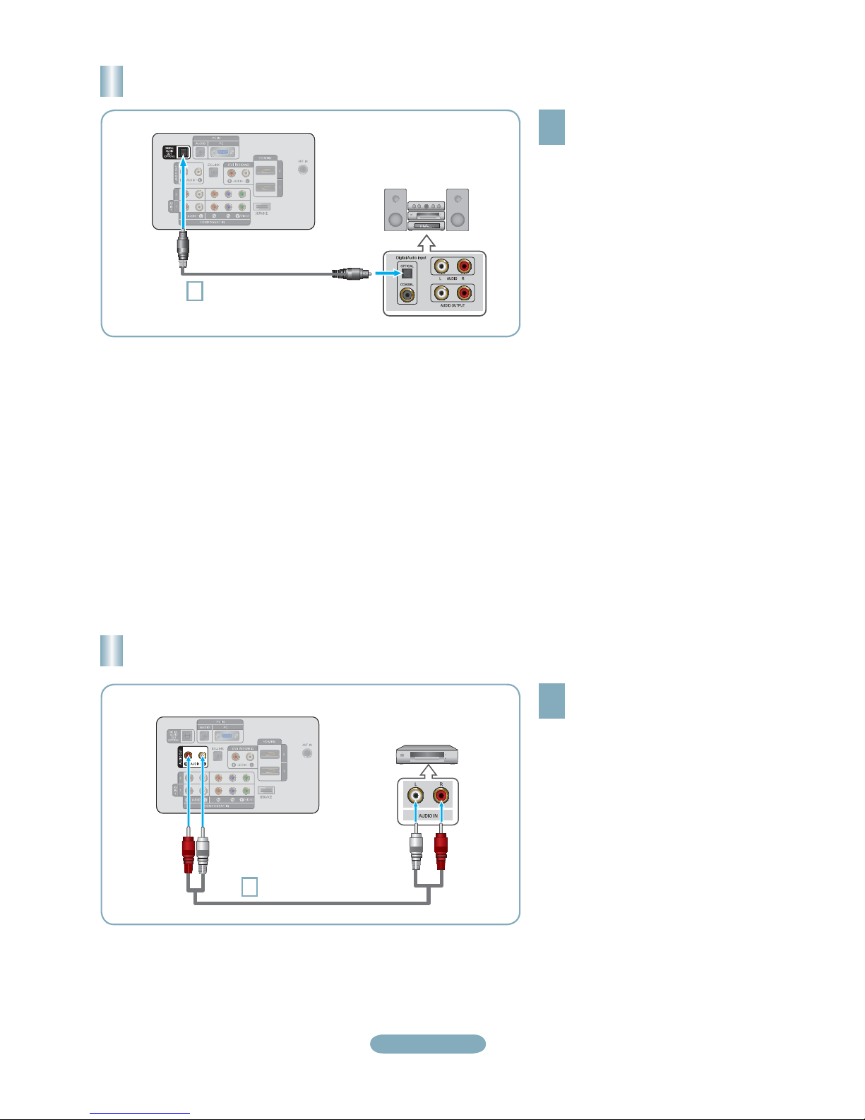
Connecting a Digital Audio System
TV Rear Panel
Optical Cable (Not supplied)
1
Digital Audio System
Connect an Optical Cable between
the “DIGITAL AUDIO OUT
1
(OPTICAL)” jacks on the TV and
the Digital Audio Input jacks on the
Digital Audio System.
When a Digital Audio System is
connected to the “DIGITAL AUDIO
OUT (OPTICAL)” jack: Decrease
the volume of the TV and adjust
the volume level with the system’s
volume control.
5.1CH audio is possible when the TV
°
is connected to an external device
supporting 5.1CH.
Each Digital Audio System has a
°
different back panel configuration.
When the receiver (home theater) is
°
set to On, you can hear sound output
from the TV’s Optical jack. When the TV
is displaying a DTV(air) signal, the TV
will send out 5.1 channel sound to the
Home theater receiver. When the source
is a digital component such as a DVD
and is connected to the TV via HDMI,
only 2 channel sound will be heard from
the Home Theater receiver. If you want
to hear 5.1 channel audio, connect the
DIGITAL AUDIO OUT (OPTICAL) jack
on the DVD player or Cable/Satellite
Box directly to an Amplifier or Home
Theater, not the TV.
Connecting an Amplifier/DVD Home Theater
Connect Audio Cables between the
AUDIO OUT [R-AUDIO-L] jacks on
TV Rear Panel
Audio Cable (Not supplied)
1
Amplifier/DVD Home Theater
English-7
1
the TV and AUDIO IN [R-AUDIO-L]
jacks on the Amplifier/DVD Home
Theater.
When an audio amplifier is
connected to the "AUDIO OUT
[R-AUDIO-L]" jacks: Decrease the
volume of the TV and adjust the
volume level with the Amplifier’s
volume control.
Each Amplifier/DVD Home Theater has
°
a different back panel configuration.
When connecting an Amplifier/DVD
°
Home Theater, match the color of the
connection terminal to the cable.
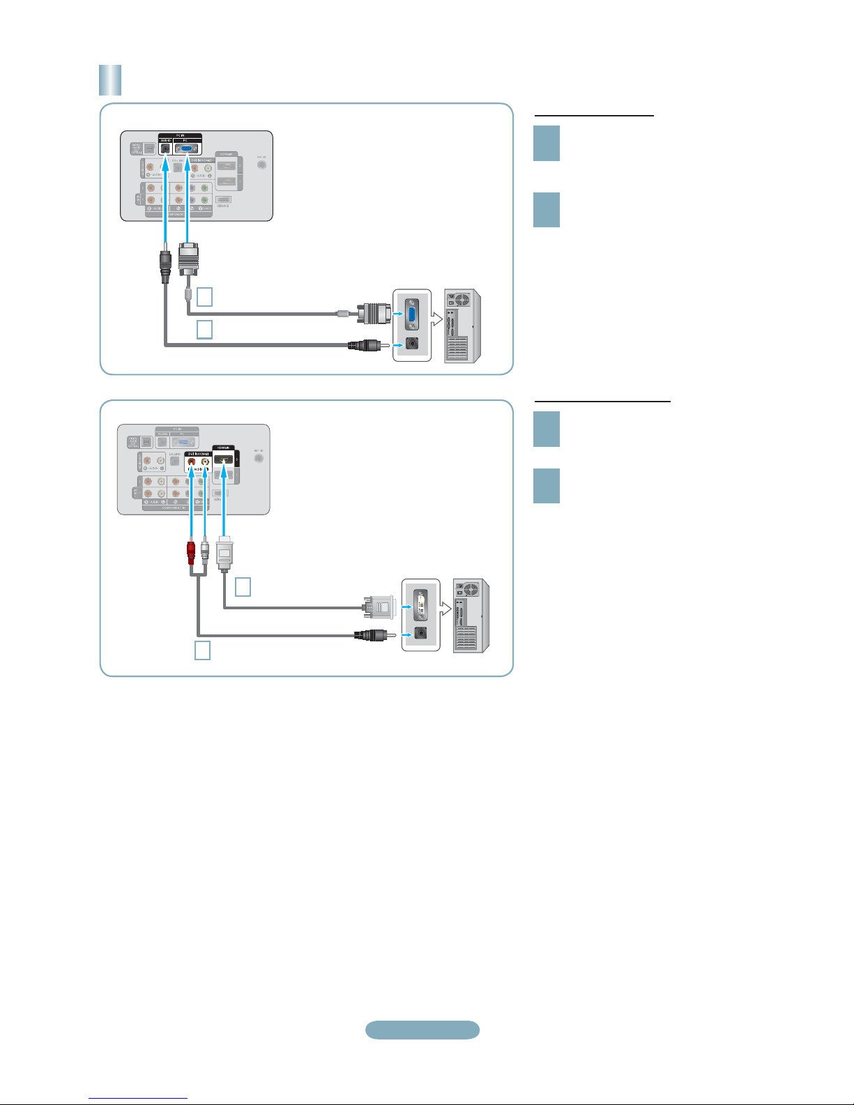
Connecting a PC
TV Rear Panel
D-Sub Cable (Not supplied)
1
PC Audio Cable (Not supplied)
2
TV Rear Panel
PC
Using the D-Sub Cable
Connect a D-Sub Cable between
PC IN [PC] connector on the TV
1
and the PC output connector on
your computer.
Connect a PC Audio Cable
between the PC IN [AUDIO] jack
2
on the TV and the Audio Out jack of
the sound card on your computer.
Using the HDMI/DVI Cable
Connect an HDMI/DVI cable between
the HDMI IN 2 jack on the TV and
1
the PC output jack on your computer.
Connect a 3.5 mm Stereo miniplug/2RCA Cable between the DVI
2
IN(HDMI2) [R-AUDIO-L] jack on the
TV and the Audio Out jack of the
sound card on your computer.
HDMI/DVI Cable (Not supplied)
1
3.5 mm Stereo mini-plug/2RCA Cable (Not supplied)
2
PC
Each PC has a different back panel
°
configuration.
When connecting a PC, match the
°
color of the connection terminal to the
cable.
When using an HDMI/DVI cable
°
connection, you must use the HDMI
IN 2 jack.
English-8

Connections (LN32A450C1D, LN37A450C1D)
Connecting a DVD Player or Cable Box/Satellite receiver (Set-Top Box) via HDMI
Connect an HDMI Cable between
the HDMI IN (1, 2 or 3) jack on
1
the TV and the HDMI jack on the
DVD Player or Cable Box/Satellite
receiver (Set-Top Box).
What is HDMI?
•
HDMI(High-Definition Multimedia
Interface), is an interface that enables the
transmission of digital audio and video
signals using a single cable.
•
The difference between HDMI and DVI
is that the HDMI device is smaller in
size and has the HDCP (High Bandwidth
Digital Copy Protection) coding feature
installed.
DVD Player or Cable Box/
Satellite receiver (Set-Top Box)
TV Rear Panel
or
HDMI Cable (Not supplied)
1
TV Side Panel
Each DVD Player or Cable Box/Satellite receiver (Set-Top Box) has a different back panel configuration.
°
Connecting a DVD Player or Cable Box/Satellite receiver (Set-Top Box) via DVI
Connect a DVI to HDMI Cable or
DVI-HDMI Adapter between the HDMI
1
IN 1 jack on the TV and the DVI jack
on the DVD Player or Cable Box/
Satellite receiver (Set-Top Box).
Connect Audio Cables between the
DVI IN (HDMI 1) [R-AUDIO-L] jack on
2
the TV and the DVD Player or Cable
Box/Satellite receiver (Set-Top Box).
DVD Player or Cable Box/
Satellite receiver (Set-Top Box)
TV Rear Panel
Audio Cable (Not supplied)
2
DVI to HDMI Cable (Not supplied)
1
Each DVD Player or Cable Box/Satellite receiver (Set-Top Box) has a different back panel configuration.
°
When connecting a DVD Player or Cable Box/Satellite receiver (Set-Top Box), match the color of the connection terminal to the
°
cable.
When using an HDMI/DVI cable connection, you must use the HDMI IN 1 jack.
°
English-9
 Loading...