

Samsung LN26A450C1DXZA Quick Guide
1-800-SAMSUNG (7267864)
Samsung Electronics America, Inc.
105 Challenger Road Ridgefield Park, NJ 07660-0511
Samsung Electronics Canada Inc., Customer Service
55 Standish Court Mississauga, Ontario L5R 4B2
Call center hours of operation (Mon-Sun 9AM-12AM EST).
To register this product please visit
www.samsung.com/global/register.
LN26A450C1D/LN32A450C1D/
LN37A450C1D/LN40A450C1D
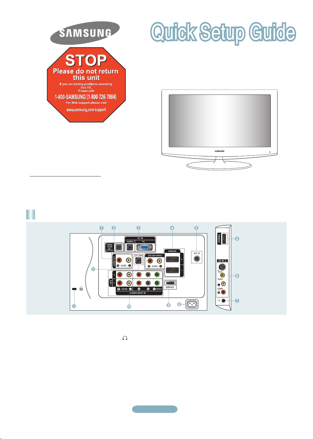
Rear Panel / Side Panel Jacks
1 AUDIO OUT
2 DIGITAL AUDIO OUT (OPTICAL)
3 PC IN [PC] / [AUDIO]
4 HDMI IN 1, 2, 3 / DVI IN (HDMI2)
[R-AUDIO-L]
5 ANT IN
6 AV IN 2
7 HEADPHONE
8 POWER INPUT
(LN26A450C1D, LN40A450C1D)
9 SERVICE
0 COMPONENT IN 1, 2 / AV IN 1
! EX-LINK
@ KENSINGTON LOCK
English-1
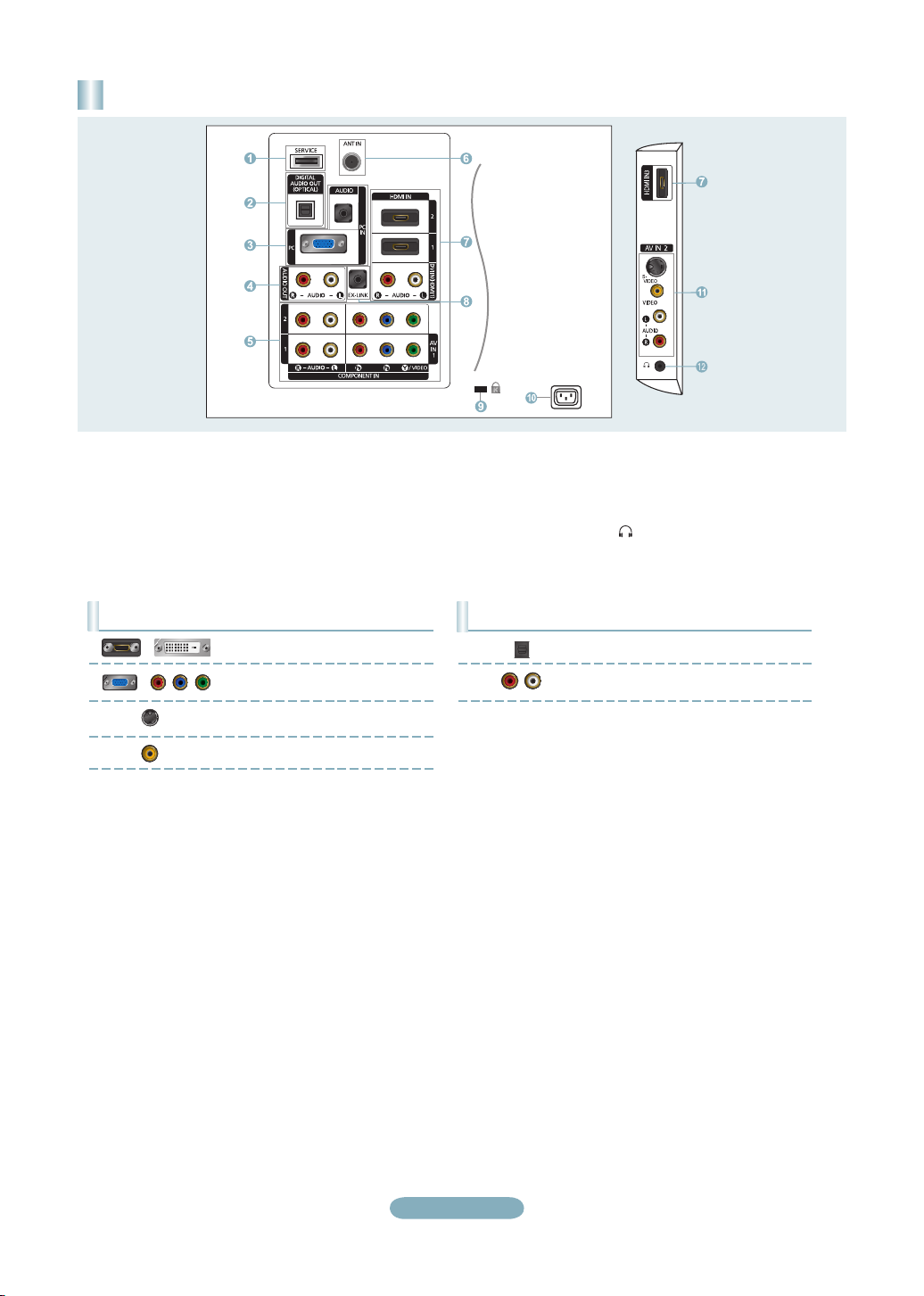
Rear Panel / Side Panel Jacks
(LN32A450C1D, LN37A450C1D)
1 SERVICE
2 DIGITAL AUDIO OUT (OPTICAL)
3 PC IN [PC] / [AUDIO]
4 AUDIO OUT
5 COMPONENT IN 1, 2 / AV IN 1
6 ANT IN
7 HDMI IN 1, 2, 3 / DVI IN (HDMI1)
[R-AUDIO-L]
8 EX-LINK
Video Input Performance Comparison
/
/
HDMI/DVI
PC/COMPONENT
S-VIDEO
VIDEO
Best
Better
Good
Normal
9 KENSINGTON LOCK
0 POWER INPUT
! AV IN 2
@ HEADPHONE
Audio Output Performance Comparison
OPTICAL (Digital)
AUDIO (Analog)
Best
Normal
English-2
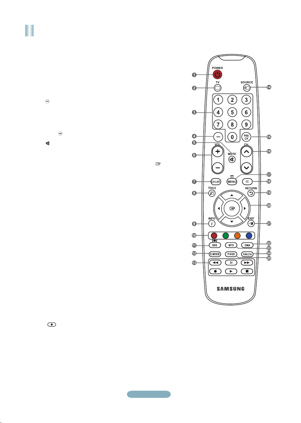
Remote Control
See “Remote Control” in the owner’s instructions for details.
1
POWER
Turns the TV on and off.
2
TV
Selects the TV mode directly.
3
NUMERIC BUTTONS
Press to change the channel.
4
Press to select additional
channels (digital and analog)
being broadcast by the same
station. For example, to select
channel “54-3”, press “54”, then
press “ ” and “3”.
5
(MUTE)
Press to temporarily cut off the
sound.
6
VOL- / VOL+
Press to increase or decrease
the volume.
7
CH LIST
Used to display Channel Lists
on the screen.
8
TOOLS
Use to quickly select frequently
used functions.
9
INFO
Press to display information on
the TV screen.
0
COLOR BUTTONS
Use these buttons in the
Channel list, etc.
!
SRS
Selects SRS TruSurround XT
mode.
@
E.MODE
Press to select the preset
display and sound modes for
sports, cinema and games.
#
Use these buttons in the DMA
and Anynet+ modes.
( : This remote can be
used to control recording on
Samsung recorders with the
Anynet+ feature)
$
SOURCE
Press to display and select the
available video sources.
%
PRE-CH
Tunes to the previous channel.
^
CH> / CH<
Press to change channels.
&
MENU
Displays the main on-screen
menu.
*
CC
Controls the caption decoder.
(
RETURN
Returns to the previous menu.
)
UP▲/DOWN▼/LEFT◄/
RIGHT►/ENTER
Use to select on-screen menu
items and change menu values.
a
EXIT
Press to exit the menu.
b
DMA (Digital Media Adapter)
Use this when connecting
a SAMSUNG DMA device
through an HDMI interface and
switching to DMA mode.
For more information on the
operating procedures, refer to
the user manual of the DMA.
This button is available when
"Anynet+(HDMI-CEC)" is "On".
c
MTS
Press to choose stereo, mono
or Separate Audio Program
(SAP broadcast).
d
FAV.CH
Press to switch to your favorite
channels.
e
P.SIZE
Picture size selection.
English-3
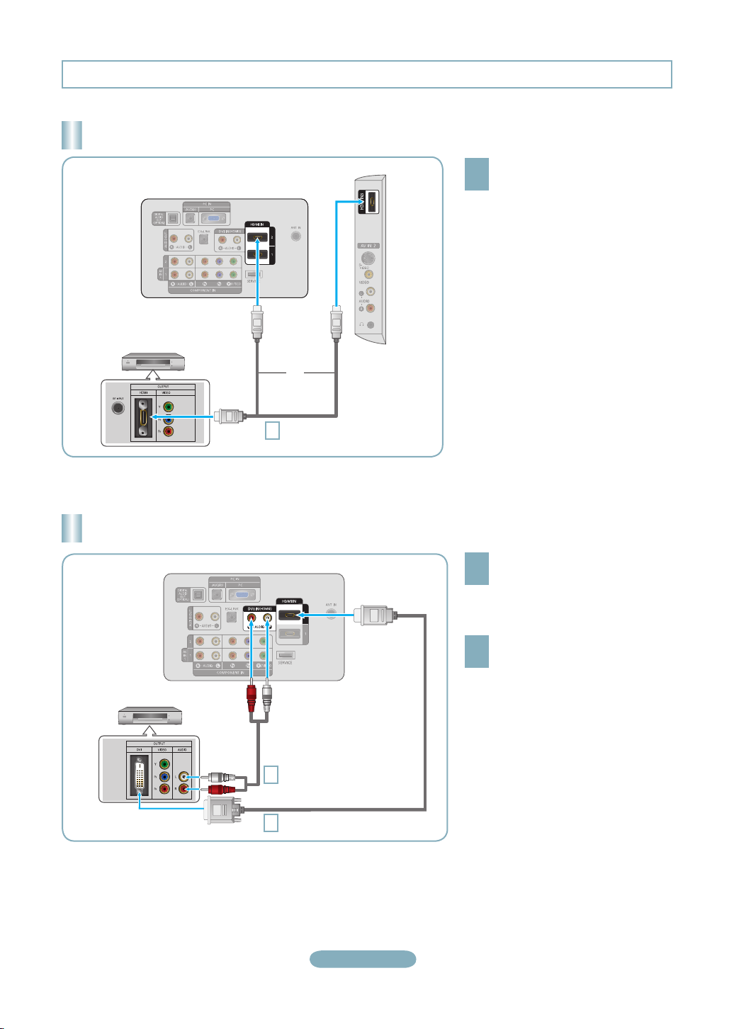
Connections (LN26A450C1D, LN40A450C1D)
Connecting a DVD Player or Cable Box/Satellite receiver (Set-Top Box) via HDMI
TV Side Panel
TV Rear Panel
DVD Player or Cable Box/
Satellite receiver (Set-Top Box)
or
HDMI Cable (Not supplied)
1
Each DVD Player or Cable Box/Satellite receiver (Set-Top Box) has a different back panel configuration.
➣
Connect an HDMI Cable between
the HDMI IN (1, 2 or 3) jack on
1
the TV and the HDMI jack on the
DVD Player or Cable Box/Satellite
receiver (Set-Top Box).
What is HDMI?
•
HDMI(High-Definition Multimedia
Interface), is an interface that enables the
transmission of digital audio and video
signals using a single cable.
•
The difference between HDMI and DVI
is that the HDMI device is smaller in
size and has the HDCP (High Bandwidth
Digital Copy Protection) coding feature
installed.
Connecting a DVD Player or Cable Box/Satellite receiver (Set-Top Box) via DVI
TV Rear Panel
DVD Player or Cable Box/
Satellite receiver (Set-Top Box)
Audio Cable (Not supplied)
2
DVI to HDMI Cable (Not supplied)
1
Each DVD Player or Cable Box/Satellite receiver (Set-Top Box) has a different back panel configuration.
➣
When connecting a DVD Player or Cable Box/Satellite receiver (Set-Top Box), match the color of the connection terminal to the
➣
cable.
When using an HDMI/DVI cable connection, you must use the HDMI IN 2 jack.
➣
Connect a DVI to HDMI Cable or
DVI-HDMI Adapter between the
1
HDMI IN 2 jack on the TV and the DVI
jack on the DVD Player or Cable Box/
Satellite receiver (Set-Top Box).
Connect Audio Cables between the
DVI IN (HDMI 2) [R-AUDIO-L] jack on
2
the TV and the DVD Player or Cable
Box/Satellite receiver (Set-Top Box).
English-4
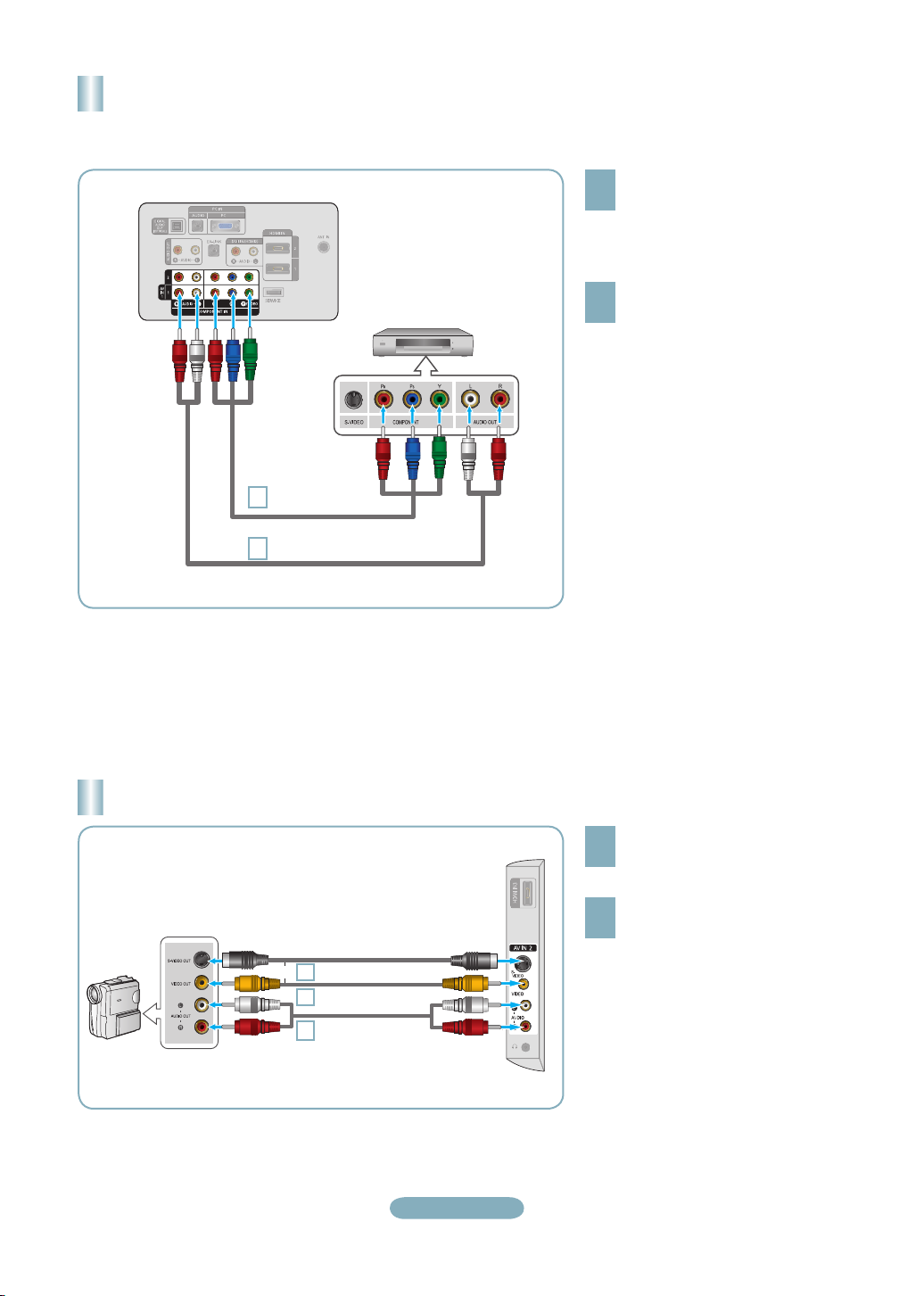
Connecting a DVD Player or Cable Box/Satellite receiver (Set-Top Box)
via Component cables
TV Rear Panel
1
2
DVD Player or Cable Box /
Satellite receiver (Set-Top Box)
Component Cable
(Not supplied)
Audio Cable (Not supplied)
Connect a Component Cable between
the COMPONENT IN (1 or 2)
1
[Y, PB, PR] jacks on the TV and the
COMPONENT [Y, PB, PR] jacks on
the DVD Player or Cable Box/Satellite
receiver (Set-Top Box).
Connect Audio Cables between the
COMPONENT IN(1 or 2) [R-AUDIO-L]
2
jacks on the TV and the AUDIO OUT
jacks on the DVD Player or Cable
Box/Satellite receiver (Set-Top Box).
Component video separates the video
➣
into Y (Luminance (brightness)), Pb
(Blue) and Pr (Red) for enhanced video
quality.
Be sure to match the component video
and audio connections.
For example, if connecting
a Component video cable to
COMPONENT IN 1, connect the audio
cable to COMPONENT IN 1 also.
Each DVD Player or Cable Box/
➣
Satellite receiver (Set-Top Box) has a
different back panel configuration.
When connecting a DVD Player or
➣
Cable Box/Satellite receiver (Set-Top
Box), match the color of the connection
terminal to the cable.
Connecting a Camcorder
Camcoder
S-Video cable (Not supplied)
or
1
Video cable (Not supplied)
1
Audio cable
2
(Not supplied)
English-5
TV Side Panel
Connect a Video Cable (or S-Video
Cable) between the AV IN 2 [VIDEO]
1
(or S-VIDEO) jack on the TV and the
VIDEO OUT jack on the camcorder.
Connect Audio Cables between the
AV IN 2 [R-AUDIO-L] jacks on the
2
TV and the AUDIO OUT jacks on the
camcorder.
Each Camcorder has a different back
➣
panel configuration.
When connecting a Camcorder, match
➣
the color of the connection terminal to
the cable.
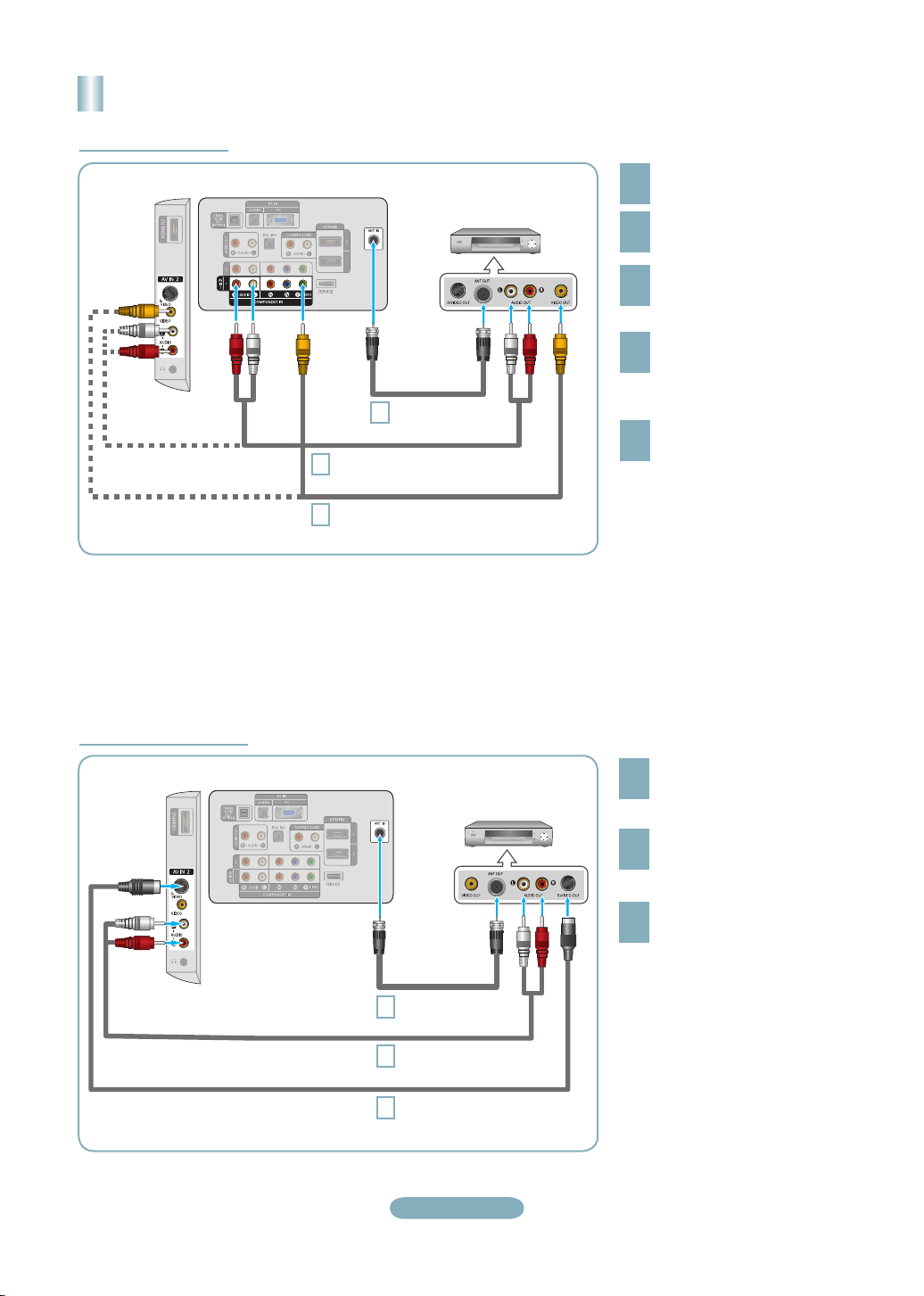
Connecting a VCR
Video Connection
TV Side Panel
Follow the instructions in “Viewing a VCR or Camcorder Tape” to view your VCR tape.
Each VCR has a different back panel configuration.
➣
When connecting a VCR, match the color of the connection terminal to the cable.
➣
When connecting to AV IN 1, the color of the AV IN 1 [Y/VIDEO] jack (Green) does not match the color of the video cable
➣
(Yellow).
TV Rear Panel
RF Cable
3
Audio Cable (Not supplied)
5
Video Cable (Not supplied)
4
VCR Rear Panel
(Not supplied)
Unplug the cable or antenna
from the back of the TV.
1
Connect the cable or antenna
to the ANT IN terminal on the
2
back of the VCR.
Connect an RF Cable between
the ANT OUT terminal on the
3
VCR and the ANT IN terminal
on the TV.
Connect a Video Cable
between the VIDEO OUT jack
4
on the VCR and the AV IN 1
[Y/VIDEO] or AV IN 2 [VIDEO]
jack on the TV.
Connect Audio Cables between
the AUDIO OUT jacks on the
5
VCR and the AV IN 1 (or AV IN 2)
[R-AUDIO-L] jacks on the TV.
If you have a “mono” (non-stereo)
➣
VCR, use a Y-connector (not
supplied) to hook up to the right
and left audio input jacks of the
TV. If your VCR is stereo, you
must connect two cables.
S-Video Connection
TV Side Panel
TV Rear Panel
VCR Rear Panel
RF Cable
1
2
3
(Not supplied)
Audio Cable (Not supplied)
S-Video Cable (Not supplied)
English-6
To begin, follow steps 1–3 in
the previous section to connect
1
the antenna or cable to your
VCR and your TV.
Connect Audio Cables between
the AUDIO OUT jacks on the
2
VCR and the AV IN 2
[R-AUDIO-L] jacks on the TV.
Connect an S-Video Cable
between the S-VIDEO OUT jack
3
on the VCR and the AV IN 2
[S-VIDEO] jack on the TV.
An S-Video cable may be included
with a VCR. (If not, check your local
electronics store.)
Each VCR has a different back
➣
panel configuration.
When connecting a VCR, match
➣
the color of the connection
terminal to the cable.
 Loading...