

Samsung LN23R51B Schematic
TFT-LCD TV/MONITOR
Chassis Model
RE23UO LN23R51B
RE26UO LN26R51B
RE32UO LN32R51B
Manual
SERVICE
TFT-LCD TV/MONITOR CONTENTS
1. Precautions
2. Product Specifications
3. Disassembly & Reassembly
4. Alignment & Adjustments
5. Troubleshooting
6. Exploded View & Parts List
7. Parts List
8. Block Diagram
9. Wiring Diagram
10. PCB Layout
11. Schematic Diagrams
12. Panel Description
❈ This Service Manual is a property of
Samsung Electronics Co., Ltd.
Any unauthorized use of Manual can be
punished under applicable International
and/or domestic law.
Samsung Electronics Co.,Ltd.
416, Maetan-3Dong, Yeongtong-Gu, Suwon City, Gyeonggi-Do,
Korea, 443-742
Printed in Korea
P/N : BN82-00128N-00
URL : http://itself.sec.samsung.co.kr/
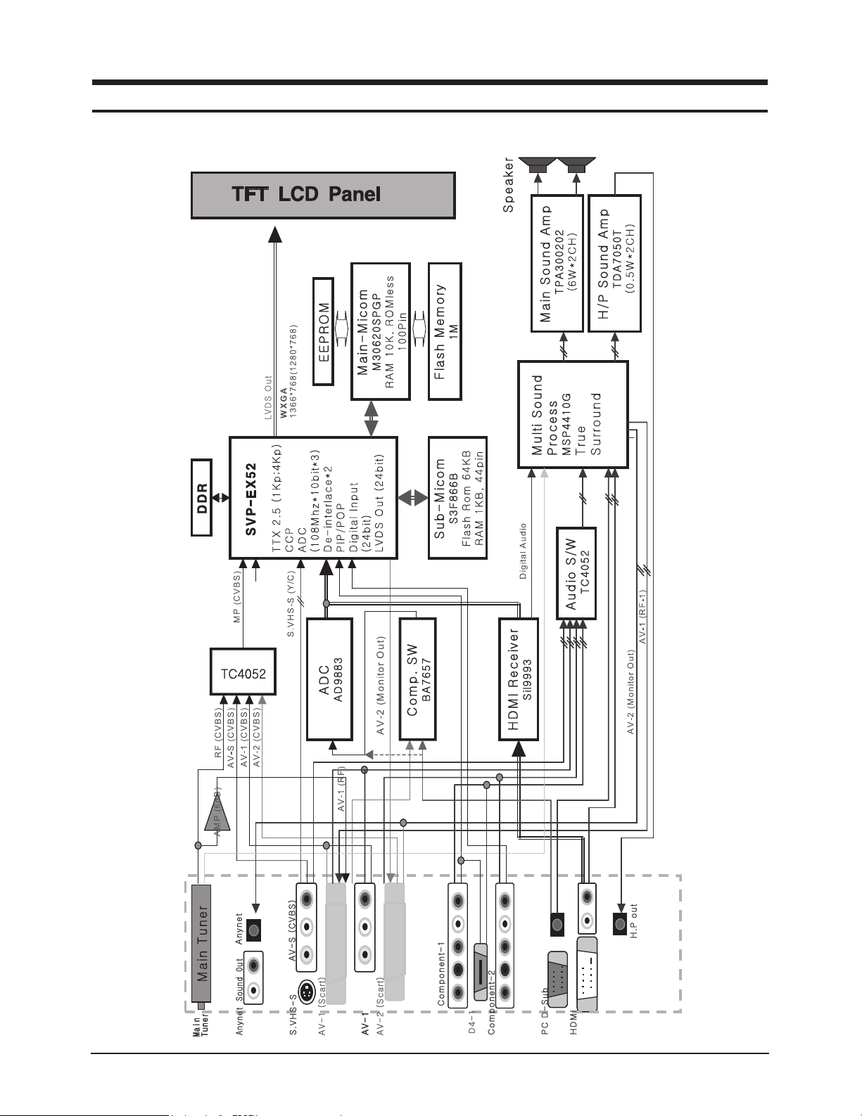
8 Block Diagram
❈ This Document can not be used without Samsung’s authorization.
8 Block Diagrams
8-1

8 Block Diagrams
Memo
8-2
3 Disassembly and Reassembly
!
!
3 Disassembly and Reassembly
This section of the service manual describes the disassembly and reassembly procedures for the
LCD TV.
WARNING: This monitor contains electrostatically sensitive devices. Use caution when
handling these components.
LN23R51B / LN26R51B / LN32R51B
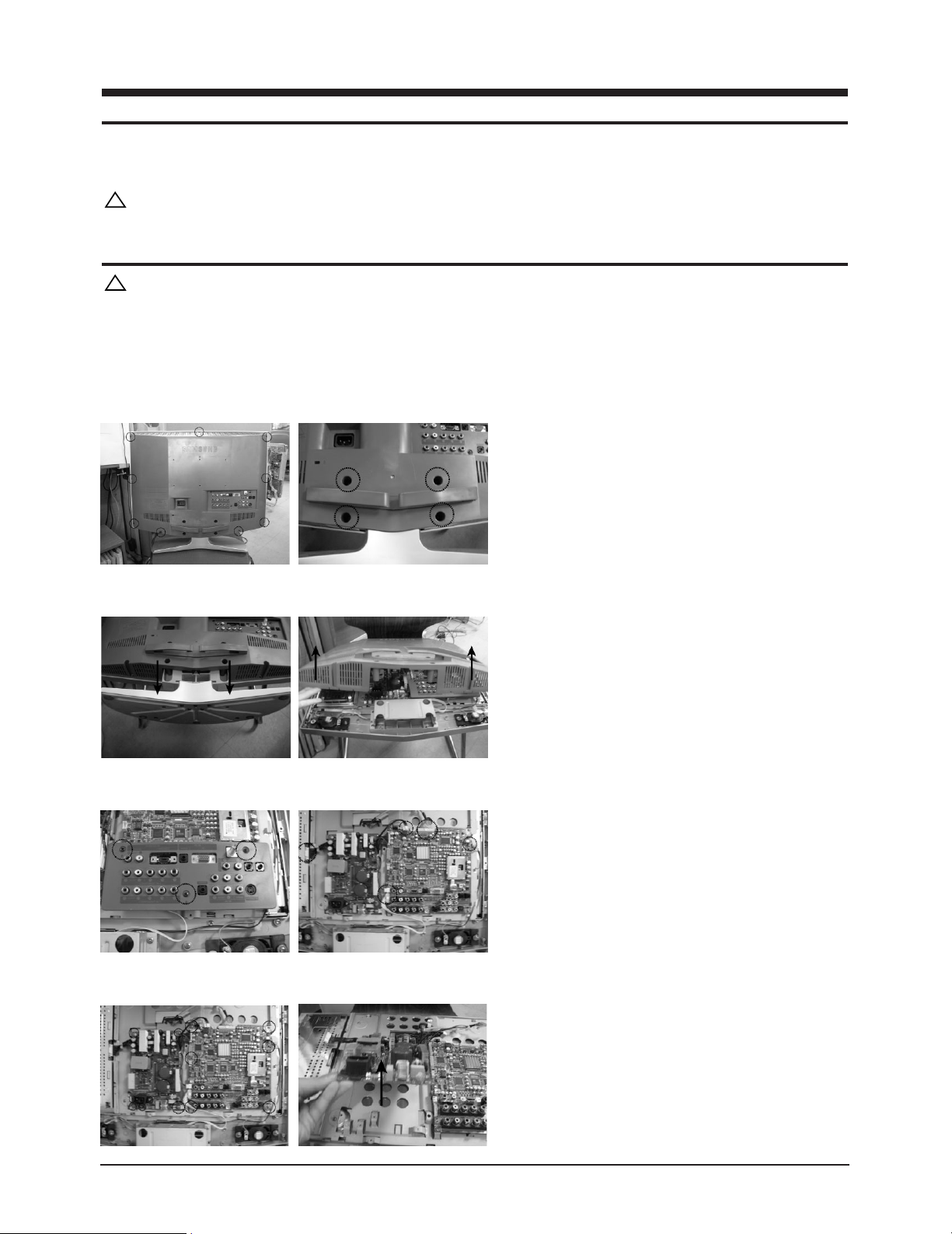
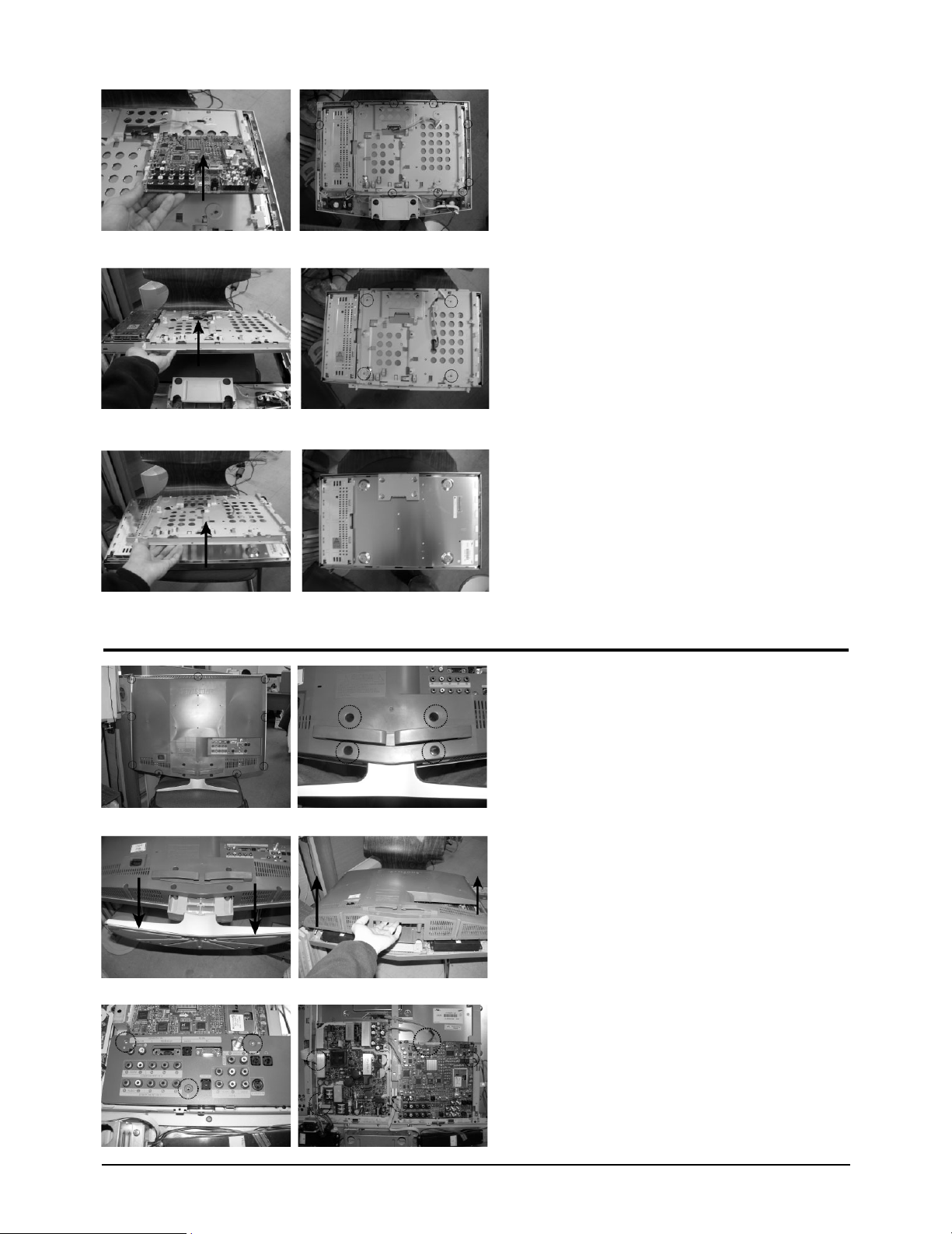
3-1 LN23R51B Disassembly
Cautions: 1. Disconnect the monitor from the power source before disassembly.
1. Place LCD TV face down on cushioned table.
Remove 9 screws from the rear cover.
Remove 4 screws from grip on the stand. and
remove the stand.
2. Remove the stand and lift up the rear cover.
3. Remove 3 screws and lift up the jack cover.
Disconnect speaker cable, function cable from the
board.
4. Remove 13 screws from the shield and lift up the
power board.
3-1
3 Disassembly and Reassembly
5. Lift up the main board.
5. Lift up the shield panel and remove 4 screws.
6. Lift up the shield cover.
3-2 LN26R51B Disassembly
1. Place LCD TV face down on cushioned table.
Remove 9 screws from the rear cover.
Remove 4 screws from grip on the stand. and
remove the stand.
2. Remove the stand and lift up the rear cover.
3. Remove 3 screws and lift up the jack cover.
Disconnect speaker cable, function cable from the
board.
3-2
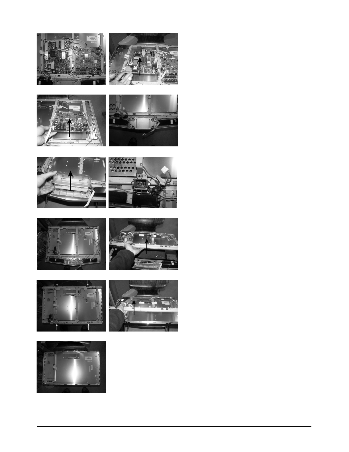
3 Disassembly and Reassembly
4. Remove 10 screws from the shield and lift up the
power board.
5. Lift up the main board.
Remove 6 screws.
6. lift up the stand BRKT.
7. Remove 9 screws from the shield and lift up the
shield panel.
8. Remove 4 screws from the shield and lift up the
BRKT.
3-3
3 Disassembly and Reassembly
3-3 LN32R51B Disassembly
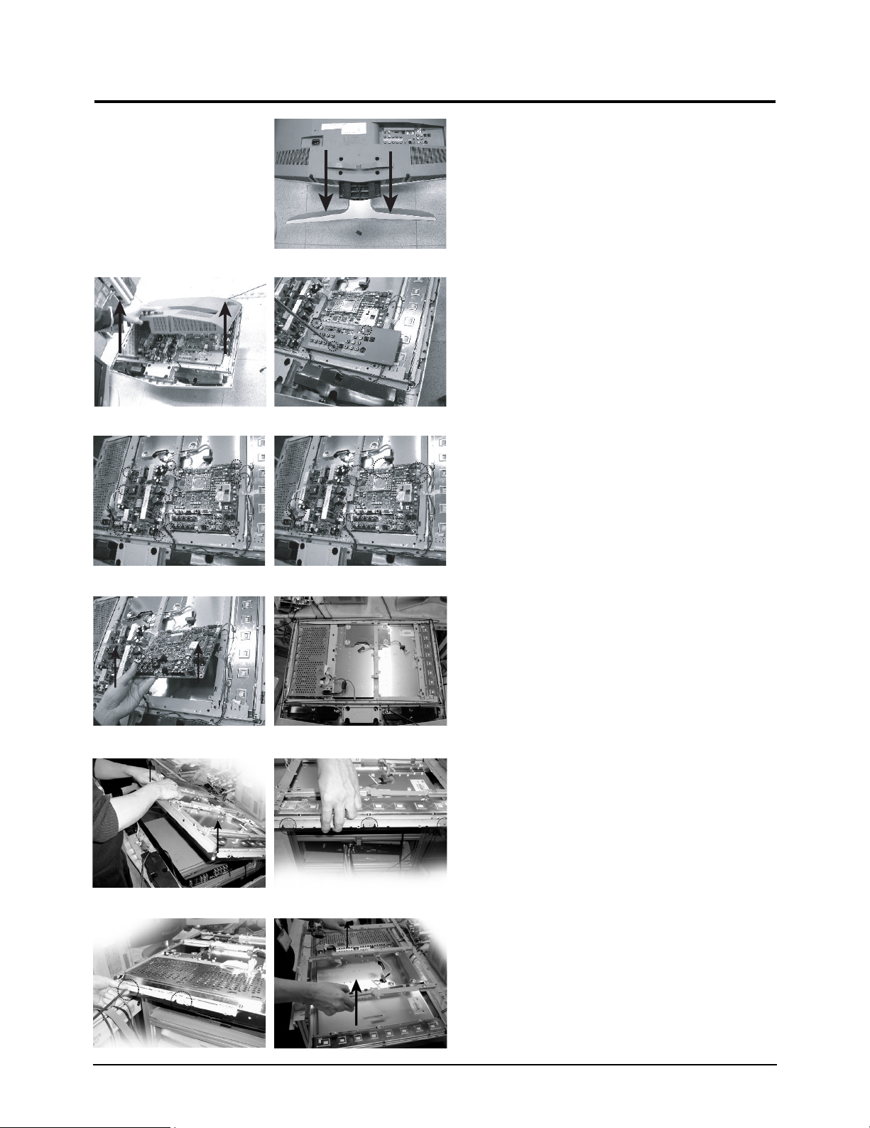
1. Place LCD TV face down on cushioned table.
Remove 14 screws from the rear cover and remove
stand.
2. Lift up the rear-cover and remove 3 screws from
the Jack cover.Remove 12 screws from The board.
3. Remove 12 screws from The board.Disconnect
speaker cable, function cable LVDS cable and lift
up the main board and power board.
4. Remove 11 screws from the shield.and lift up the
shield.
5. Remove 5 screws(Left :2/Right :3)
6. Lift up the BRKT.
3-4
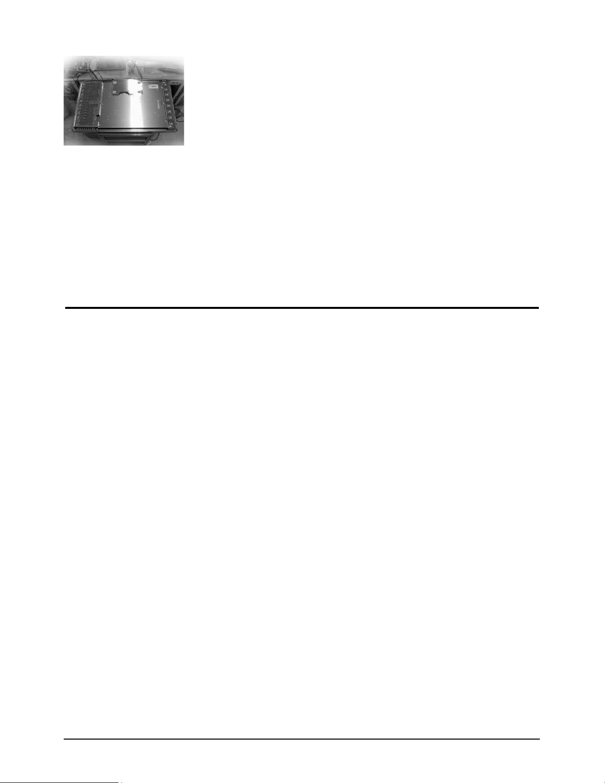
3-3 Reassembly
3 Disassembly and Reassembly
7. This picture is panel.
Reassembly procedures are in the reverse order of dissasembly procedures.
3-5

3 Disassembly and Reassembly
Memo
3-6
6 Exploded View & Parts List
6-1
T0175
6 Exploded View and Parts List
❈ You can search for updated part codes through ITSELF web site.
URL : http://itself.sec.samsung.co.kr/
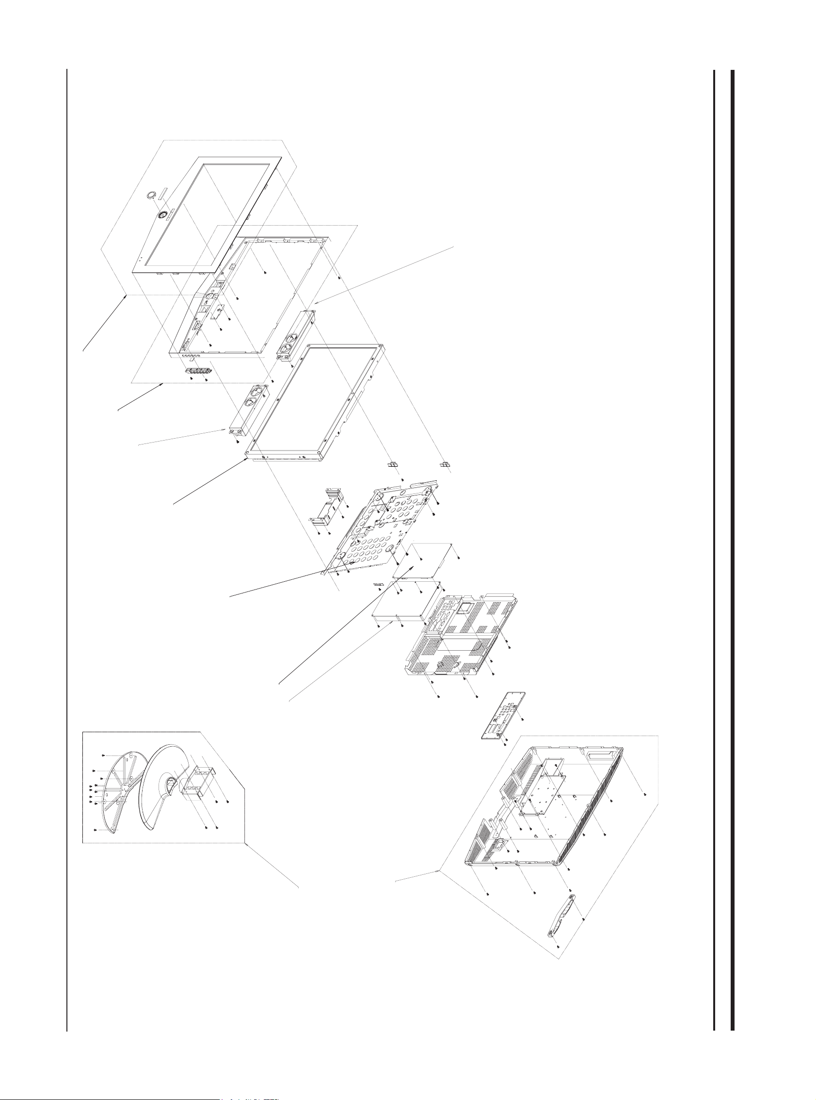
6-1 LN23R51B
T0003
T0852
T0175
M0019
M0107
M0014
T0159
M0216
M0013

6 Exploded View & Parts List
6-2
Location Code.NO Item & specification Q’ty SA/SNA
T0003 BN96-01723A ASSY COVER P-FRONT;ROME,23UO,ABS,HB,BK23 1
T0852 BN96-01724A ASSY COVER P-MIDDLE;ROME,23UO,HIPS,V0,GR 1
T0175 BN96-02450A ASSY SPEAKER P;16ohm,Right,5W,680mm,VE R 1
M0019 BN07-00184A LCD;LTA230W1-L02,8bit,546*318*46.3,16.7M 1
M0107 BN61-01569A BRACKET-PCB;23,ROME,SECC,T1.0 1 S.N.A
M0014 BN94-00629B ASSY PCB MAIN;RE23UO 1
T0159 BN96-01850D ASSY PCB P-SMPS;110W SMPS,RE23EO,120*185 1
M0013 BN96-01725A ASSY COVER P-REAR;ROME,23,HIPS,V0,GR503 1
T0175 BN96-02449A ASSY SPEAKER P;16ohm,Left,5W,320mm,VE RO 1
M0216 BN90-00697A ASSY STAND;RE23 1 S.N.A
6 Exploded View & Parts List
6-3
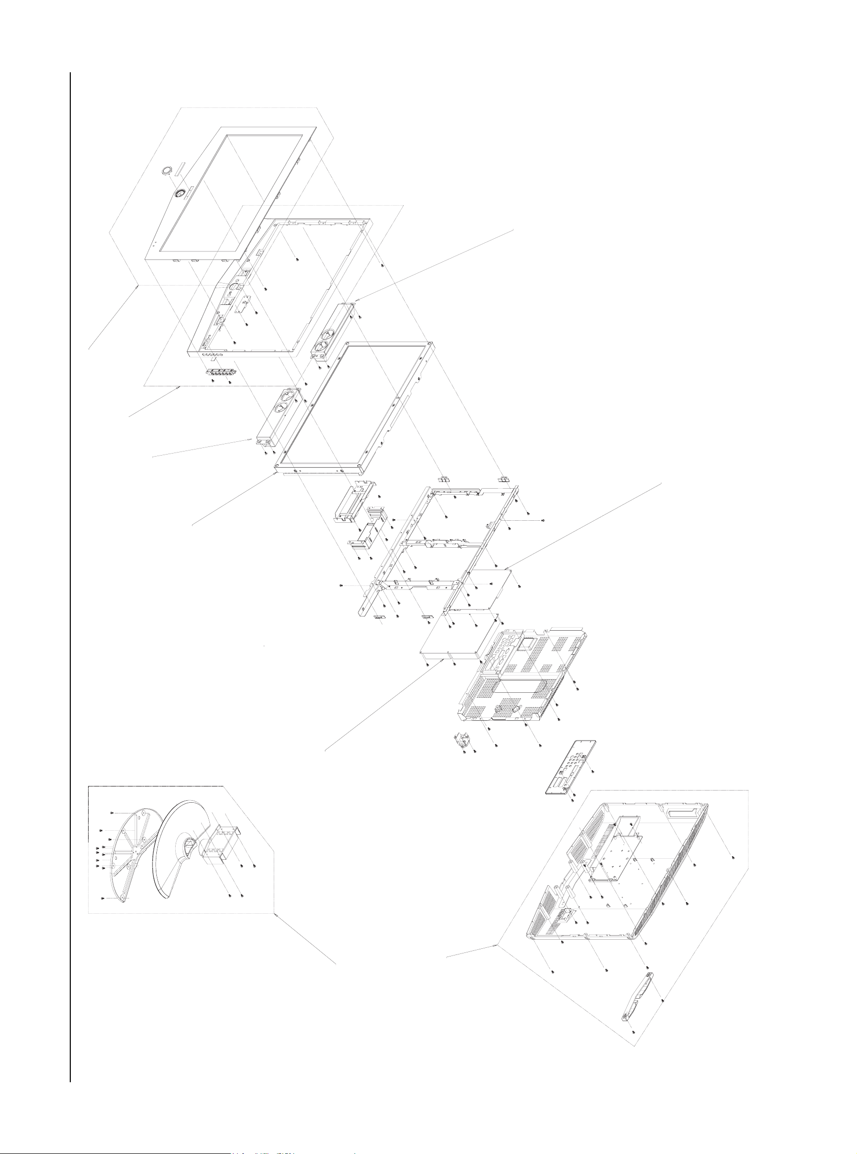
6-2 LN26R51B
6-3
T0175
T0003
T0003
T0175
M0014
M0215
T0120
M0130
M0216

6 Exploded View & Parts List
6-4
Location Code.NO Item & specification Q’ty SA/SNA
T0003 BN96-01728A ASSY COVER P-FRONT;ROME,26UO,ABS,HB,BK23 1
T0003 BN96-01728A ASSY COVER P-FRONT;ROME,26UO,ABS,HB,BK23 1
T0175 BN96-01770A ASSY SPEAKER P;16ohm,Right,5W,Rome 26 1
M0215 BN07-00239A LCD-PANEL;LTA260W2-L11,8bit,626.0*373.0* 1
T0120 BN94-00699D ASSY PCB POWER;ROME,32",Free Volt,CIS,## 1
M0013 BN96-01736B ASSY COVER P-REAR;ROME,26,HIPS,HB,GR503 1
T0175 BN96-01769A ASSY SPEAKER P;16ohm,Left,5W,Rome 26 1
M0014 BN94-00629C ASSY PCB MAIN;RE26UO 1
M0216 BN90-00694A ASSY STAND;RE26 1 S.N.A
6 Exploded View & Parts List
6-5
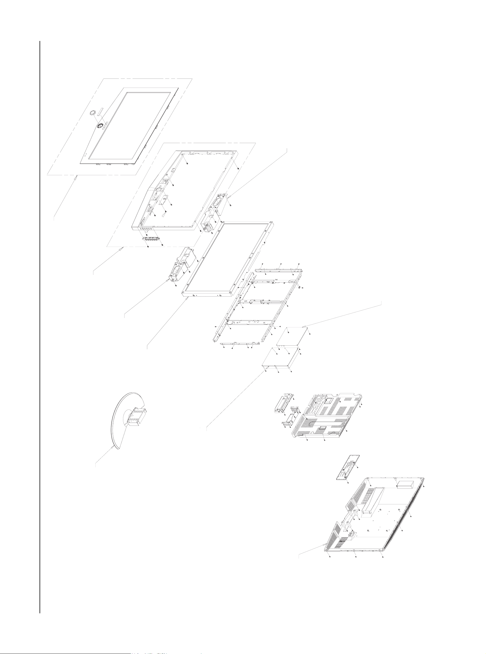
6-3 LN32R51B
T0175
T0003
M0215
M0014
T0175
M0215
M0216
T0120
M0013
6 Exploded View & Parts List
6-6
Location Code.NO Item & specification Q’ty SA/SNA
T0003 BN96-01735B ASSY COVER P-FRONT;ROME,32UO,ABS,HB,BK23 1
M0215 BN07-00194A LCD-PANEL;T315XW01,8bit,760.0*450.0*47.2 1
T0175 BN96-02453A ASSY SPEAKER P;8ohm,Left,10W,500mm,VE RO 1
T0175 BN96-02454A ASSY SPEAKER P;8ohm,Right,10W,700mm,VE R 1
T0120 BN94-00699D ASSY PCB POWER;ROME,32",Free Volt,CIS,## 1
M0014 BN94-00667S ASSY PCB MAIN-AUO;LNR328WX/XAA 1
M0013 BN96-01732A ASSY COVER P-REAR;ROME,32,HIPS,HB,GR503 1
M0014 BN94-00667S ASSY PCB MAIN-AUO;LNR328WX/XAA 1
M0216 BN90-00688A ASSY STAND;RE32 1 S.N.A
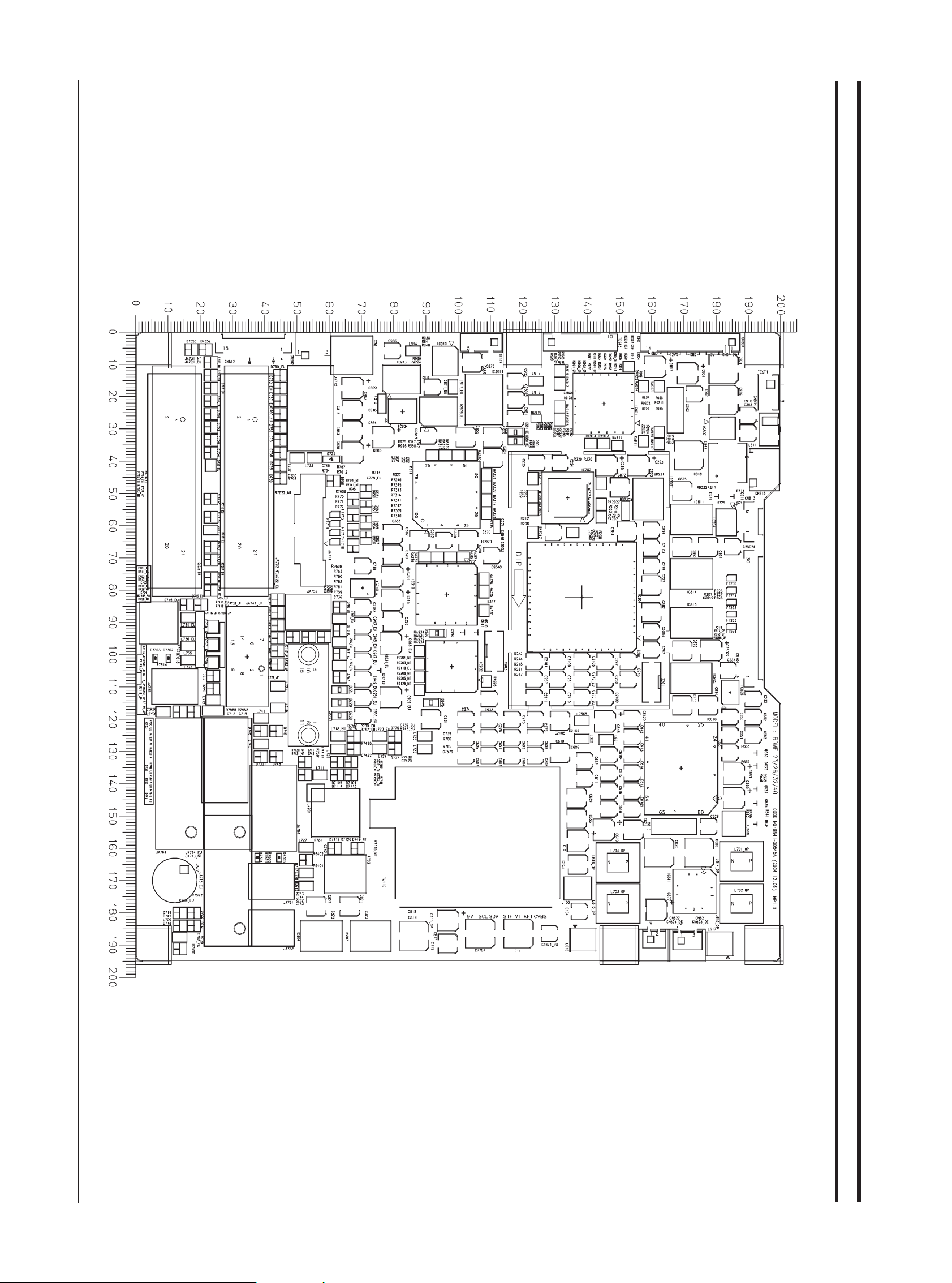
10 PCB Layout
10-1
10 PCB Layout
10-1 Main PCB Layout
X
Y
10 PCB Layout
10-2
D101 DIODE-SWITCHING 175.2 138.4
D102 DIODE-ZENER 166.0 118.4
D210 DIODE-ZENER 105.8 145.6
D211 DIODE-ZENER 100.2 146.6
D212 DIODE-ZENER 99.0 130.8
D213 DIODE-ZENER 104.2 130.8
D214 DIODE-ZENER 109.4 130.8
D215 DIODE-ZENER 108.8 145.6
D216 DIODE-ZENER 102.4 123.2
D217 DIODE-ZENER 107.6 122.8
D617 DIODE-ZENER 138.4 191.6
D620 DIODE-ZENER 160.0 172.8
D621 DIODE-ZENER 144.0 187.0
D622 DIODE-ARRAY 144.0 191.6
D702 DIODE-ZENER 29.2 23.2
D704 DIODE-ZENER 37.2 23.2
D706 DIODE-ZENER 25.2 23.2
D708 DIODE-ZENER 33.2 23.2
D7102 DIODE-SWITCHING 76.0 45.6
D7103 DIODE-SWITCHING 76.0 50.0
D7104 DIODE-SWITCHING 133.2 66.8
D7105 DIODE-SWITCHING 133.2 62.4
D7108 DIODE-ZENER 46.0 50.4
D7109 DIODE-ZENER 46.0 56.0
D7110 DIODE-ZENER 42.0 50.4
D7111 DIODE-ZENER 42.0 56.0
D7112 DIODE-ZENER 160.0 61.6
D7113 DIODE-SWITCHING 137.2 66.8
D7114 DIODE-SWITCHING 137.2 62.4
D717 DIODE-ZENER 163.6 52.8
D718 DIODE-ZENER 191.2 13.6
D719 DIODE-SWITCHING 180.0 13.6
D720 DIODE-ZENER 110.4 24.0
D721 DIODE-ZENER 117.6 13.6
D722 DIODE-SWITCHING 180.0 18.0
D723 DIODE-ZENER 106.4 24.0
D724 DIODE-ZENER 117.6 18.0
D725 DIODE-ZENER 39.2 60.6
D7301 DIODE-ZENER 131.6 38.8
D7302 DIODE-TVS 101.0 10.0
D7303 DIODE-TVS 101.0 6.0
D7304 DIODE-TVS 162.8 37.6
D7305 DIODE-TVS 162.8 44.4
D736_NT DIODE-ZENER 51.6 23.2
D741 DIODE-SWITCHING 184.0 18.0
D742 DIODE-SWITCHING 184.0 13.6
D743 DIODE-ZENER 137.2 52.4
Loc. No. Description X Y
D744 DIODE-ZENER 133.2 52.4
D745 DIODE-ZENER 123.6 43.6
D746 DIODE-ZENER 123.6 38.8
D747 C-CER,CHIP 128.4 42.8
D748 DIODE-ZENER 131.6 43.6
D749_NT DIODE-ZENER 160.0 68.8
D750 DIODE-ZENER 45.2 44.8
D751 DIODE-ZENER 42.6 71.8
D752 DIODE-ZENER 42.6 67.0
D7551 DIODE-ZENER 125.2 67.6
D7552 DIODE-ZENER 5.2 21.6
D7553 DIODE-ZENER 5.2 17.2
D756 DIODE-ZENER 29.2 44.8
D758 DIODE-ZENER 37.2 44.8
D759 DIODE-ZENER 41.2 44.8
D761 DIODE-ZENER 33.2 44.8
D763 DIODE-ZENER 98.8 44.0
D764 DIODE-ZENER 94.4 48.8
D765 DIODE-ZENER 94.4 53.6
D766 DIODE-ZENER 94.4 58.4
D767 DIODE-ZENER 106.8 63.2
D769 DIODE-ZENER 118.8 63.2
D770 DIODE-ZENER 114.8 63.2
D771 DIODE-ZENER 110.8 63.2
D772 DIODE-ZENER 129.2 93.6
D773 DIODE-ZENER 129.2 89.2
D774 DIODE-ZENER 125.2 89.2
D775 DIODE-ZENER 125.2 93.6
D776 DIODE-ZENER 125.2 80.4
D777 DIODE-ZENER 129.2 80.4
D778 DIODE-ZENER 129.2 67.6
D779 DIODE-ZENER 164.4 53.2
D780 DIODE-ZENER 176.4 53.2
D781 DIODE-ZENER 172.4 53.2
D782 DIODE-ZENER 168.4 53.2
D791_NT DIODE-SWITCHING 94.8 44.0
D792_NT DIODE-SWITCHING 90.8 44.0
D793_NT DIODE-SWITCHING 76.0 23.2
D794_NT DIODE-SWITCHING 80.0 23.2
D795_NT DIODE-SWITCHING 86.8 44.0
D796_NT DIODE-SWITCHING 82.8 44.0
D812 DIODE-RECTIFIER 35.4 182.4
D901 DIODE-ZENER 33.2 110.8
D911 DIODE-ARRAY 85.2 70.4
D912 DIODE-ARRAY 67.2 72.2
D930 DIODE-ZENER 93.2 93.4
D950 DIODE-SWITCHING 51.6 67.4
D951 DIODE-SWITCHING 49.2 71.4
Loc. No. Description X Y
DIODE
D952 DIODE-SWITCHING 56.4 67.4
D953 DIODE-SWITCHING 54.0 71.4
D954 DIODE-SWITCHING 61.2 67.4
D955 DIODE-SWITCHING 58.8 71.4
D956 DIODE-SWITCHING 66.0 67.4
D957 DIODE-SWITCHING 63.6 71.4
D958 DIODE-ZENER 46.0 61.2
D959 DIODE-ZENER 46.0 61.2
D960 DIODE-ZENER 42.0 61.2
D961 DIODE-ZENER 66.6 66.4
D962 DIODE-ZENER 48.0 69.0
D963 DIODE-ARRAY 112.6 98.6
D964 DIODE-ARRAY 112.6 103.0
D970 DIODE-ZENER 5.2 30.6
D971 DIODE-ZENER 5.2 35.0
D972 DIODE-ZENER 5.2 39.2
D973 DIODE-ZENER 5.2 21.4
D974 DIODE-ZENER 5.2 16.8
D975 DIODE-ZENER 114.8 91.6
D976 DIODE-ARRAY 106.0 88.0
D990 DIODE-ZENER 5.2 44.8
IC201 IC-VIDEO PROCESS 82.0 138.4
IC202 IC-DRAM 51.2 134.0
IC203 IC-ANALOG MULTIPLEX 125.0 133.4
IC204 IC-OP AMP 58.8 183.2
IC3011 IC-POSI.FIXED REG. 20.8 108.0
IC311 IC-RECEIVER 50.4 96.4
IC312 IC-A/D CONVERTER 81.2 96.4
IC313 IC-CMOS LOGIC 38.4 80.6
IC605 IC-ANALOG MULTIPLEX 133.8 131.2
IC610 IC-SOUND PROCESSOR 135.2 169.2
IC611 IC-AUDIO AMP 173.4 173.4
IC615 IC-AUDIO AMP 135.2 168.0
IC616 IC-VOL. DETECTOR 152.4 185.6
IC710 IC-EEPROM 79.2 70.4
IC712 IC-EEPROM 72.8 70.4
IC801 IC-POSI.FIXED REG. 20.0 70.8
IC802 IC-POSI.FIXED REG. 107.2 172.4
IC803 IC-POSI.FIXED REG. 187.2 72.8
IC804 IC-POSI.FIXED REG. 187.2 57.6
IC805 FET-SILICON 111.6 184.4
IC807 IC-SWITCH VOL. REG. 30.0 182.0
IC808 IC-POSI.FIXED REG. 52.0 159.0
IC811 IC-POSI.FIXED REG. 58.0 172.4
IC812 IC-POSI.FIXED REG. 30.4 70.8
IC813 IC-POSI.FIXED REG. 90.0 172.4
Loc. No. Description X Y
IC814 IC-POSI.FIXED REG. 74.8 172.4
IC901 IC-MICROCOMPUTER 22.0 145.2
IC902 IC-MICROCONTROLLER 103.6 98.0
IC904 IC-CMOS LOGIC 24.4 82.8
IC905 IC-RESET 120.0 91.6
IC908 IC-FLASH MEMORY 20.0 136.4
IC910 IC-EEPROM 8.8 96.0
IC913 IC-ANALOG SWITCH 14.4 82.4
IC920 IC-VOL. DETECTOR 112.8 91.6
IC931 IC-DRIVER/RECEIVER 24.8 110.4
Q100 TR-SMALL SIGNAL 165.6 137.2
Q211 TR-SMALL SIGNAL 50.8 185.6
Q215 TR-SMALL SIGNAL 124.8 149.8
Q216 TR-SMALL SIGNAL 124.8 144.8
Q221 TR-SMALL SIGNAL 50.8 180.8
Q608 TR-SMALL SIGNAL 138.4 187.2
Q610 TR-SMALL SIGNAL 148.8 186.8
Q611 TR-SMALL SIGNAL 128.0 168.8
Q612 TR-SMALL SIGNAL 128.0 164.8
Q615 TR-SMALL SIGNAL 132.8 191.6
Q620 TR-SMALL SIGNAL 152.8 191.6
Q630 TR-SMALL SIGNAL 130.4 192.8
Q631 TR-SMALL SIGNAL 127.2 191.6
Q632 TR-SMALL SIGNAL 134.4 192.8
Q633 TR-SMALL SIGNAL 141.6 192.8
Q634 TR-SMALL SIGNAL 152.4 192.8
Q635 TR-SMALL SIGNAL 146.0 192.8
Q801 TR-SMALL SIGNAL 101.6 177.0
Q802 TR-SMALL SIGNAL 113.6 177.0
Q803 TR-SMALL SIGNAL 4.8 84.8
Q910 TR-SMALL SIGNAL 93.0 106.2
Q911 TR-SMALL SIGNAL 93.0 102.0
Q914 FET-SILICON 12.8 117.6
Q915 FET-SILICON 16.8 117.6
Q918 TR-SMALL SIGNAL 19.2 167.2
Q920 FET-SILICON 16.8 109.6
Q921 FET-SILICON 12.8 109.6
Q922 FET-SILICON 143.5 182.1
Q923 FET-SILICON 139.8 182.1
Q930 TR-SMALL SIGNAL 12.8 83.6
Q931 TR-SMALL SIGNAL 152.8 186.8
Q952 TR-SMALL SIGNAL 77.6 70.4
Q960 FET-SILICON 19.2 171.6
Q970 TR-SMALL SIGNAL 22.4 94.4
Q971 TR-SMALL SIGNAL 37.2 66.8
Loc. No. Description X Y
IC
TRANSISTOR
2 Product Specifications
2-1 LN23R51B Specifications
2 Product Specifications
Item
LCD Panel
Scanning Frequency Horizontal : 30 kHz ~ 61 kHz (Automatic)
Display Colors 16.7 Million colors
Maximum Resolution Horizontal : 1360 Pixels
Input Video Signal Analog 0.7 Vp-p ± 5% positive at 75 Ω, internally terminated
Input Sync Signal Type : Seperate H/V
Maximum Pixel Clock rate
Active Display
Horizontal/Vertical
AC power voltage & Frequency
Power Consumption 100 W
Dimensions(W x D x H)
Set 22.95 x 3.54 x 17.44 inches(583.0 x 90.0 x 443.0 mm) Body
TFT-LCD panel, RGB vertical stripe, normaly white, 23-Inch viewable, 0.372 (H) x 0.372(V)mm pixel pitch
Vertical : 60 Hz ~ 75 Hz (Automatic)
Vertical : 768 Pixels
Level : TTL level
80 MHz
556.4 mm / 339.8 mm
AC 110 ~ 120 V, 60 Hz
Description
22.95 x 8.11 x 19.10 inches (583.0 x 206.0 x 484.7 mm) With stand
Weight
Set(With stand) 18.96 lbs (8.6 kg)
Environmental Considerations
TV System
Antena Input 75Ω
Sound Characteristic
Operating Temperature : 50 °F ~ 104 °F (10 °C ~ 40 °C)
Operating Humidity : 10 % ~ 80 %
Storage Temperature : -4 °F ~ 113 °F (-20 °C ~ 45 °C)
Storage Humidity : 5 % ~ 95 %
Tunning Frequency Synthesize
System NTSC
Sound STEREO
– MAX Internal speaker Out : Right => 3W, Left => 3W
– BASS Control Range : -8 dB ~ + 8dB
– TREBLE Control Range : -8 dB ~ +8 dB
– Headphone Out : 10 mW MAX
– Output Frequency : RF : 80 Hz ~ 15 kHz
A/V : 80 Hz ~ 20 kHz
2-1
2 Product Specifications
2-2 LN26R51B Specifications
Item
LCD Panel
Scanning Frequency Horizontal : 30 kHz ~ 61 kHz (Automatic)
Display Colors 16.7 Million colors
Maximum Resolution Horizontal : 1360 Pixels
Input Video Signal Analog 0.7 Vp-p ± 5% positive at 75 Ω, internally terminated
Input Sync Signal Type : Seperate H/V
Maximum Pixel Clock rate
Active Display
Horizontal/Vertical
AC power voltage & Frequency
Power Consumption 140 W
Dimensions(W x D x H)
TFT-LCD panel, RGB vertical stripe, normaly white, 26-Inch viewable, 0.4215 (H) x 0.4215(V)mm pixel pitch
Vertical : 60 Hz ~ 75 Hz (Automatic)
Vertical : 768 Pixels
Level : TTL level
80 MHz
556.4 mm / 339.8 mm
AC 110 ~ 120 V, 60 Hz
Description
Set 26.06 x 3.70 x 19.60 inches (662.0 x 94.0 x 497.8 mm) Body
26.06 x 8.11 x 21.22 inches (662.0 x 206.0 x 539.0 mm) With stand
Weight
Set(With stand) 33.07 lbs (15.0 kg)
Environmental Considerations Operating Temperature : 50 °F ~ 104 °F (10 °C ~ 40 °C)
Operating Humidity : 10 % ~ 80 %
Storage Temperature : -4 °F ~ 113 °F (-20 °C ~ 45 °C)
Storage Humidity : 5 % ~ 95 %
Tunning Frequency Synthesize
TV System
Antena Input 75Ω
– MAX Internal speaker Out : Right => 5W, Left => 5W
Sound Characteristic
– BASS Control Range : -8 dB ~ + 8dB
– TREBLE Control Range : -8 dB ~ +8 dB
– Headphone Out : 10 mW MAX
– Output Frequency : RF : 80 Hz ~ 15 kHz
System NTSC
Sound STEREO
A/V : 80 Hz ~ 20 kHz
2-2
2-3 LN32R51B Specifications
Item
2 Product Specifications
Description
LCD Panel
Scanning Frequency Horizontal : 30 kHz ~ 61 kHz (Automatic)
Display Colors 16.7 Million colors
Maximum Resolution Horizontal : 1360 Pixels
Input Video Signal Analog 0.7 Vp-p ± 5% positive at 75 Ω, internally terminated
Input Sync Signal Type : Seperate H/V
Maximum Pixel Clock rate
Active Display
Horizontal/Vertical
AC power voltage & Frequency
Power Consumption 184 W
Dimensions(W x D x H)
Set 31.38 x 3.898 x 23.31 inches (797.0 x 99.0 x 592.0 mm) With stand
TFT-LCD panel, RGB vertical stripe, normaly white, 32-Inch viewable, 0.511 (H) x 0.511(V)mm pixel pitch
Vertical : 60 Hz ~ 75 Hz (Automatic)
Vertical : 768 Pixels
Level : TTL level
80 MHz
556.4 mm / 339.8 mm
AC 110 ~ 120 V, 60 Hz
31.38 x 9.80 x 25.62 inches (797.0 x 249.0 x 650.7 mm) Body
Weight
Set
(With Stand)
Environmental Considerations Operating Temperature : 50 °F ~ 104 °F (10 °C ~ 40 °C)
TV System
Antena Input 75Ω
Sound Characteristic
39.02 Ibs (17.7 Kg)
Operating Humidity : 10 % ~ 80 %
Storage Temperature : -4 °F ~ 113 °F (-20 °C ~ 45 °C)
Storage Humidity : 5 % ~ 95 %
Tunning Frequency Synthesize
System NTSC
Sound STEREO
– MAX Internal speaker Out : Right => 10W, Left => 10W
– BASS Control Range : -8 dB ~ + 8dB
– TREBLE Control Range : -8 dB ~ +8 dB
– Headphone Out : 10 mW MAX
– Output Frequency : RF : 80 Hz ~ 15 kHz
A/V : 80 Hz ~ 20 kHz
2-3
2 Product Specifications
2-4 Pin Assignments
2-4-1 HDMI
Type A pin
1
2
3
4
5
6
7
8
9
10
11
12
13
14
Singnal Name
TMDS Data2+
TMDS Data2 Shield
TMDS Data2-
TMDS Data1+
TMDS Data2 Shield
TMDS Data1-
TMDS Data0+
TMDS Data0 Shield
TMDS Data0-
TMDS Clock+
TMDS Clock Shield
TMDS Clock-
CEC
Reserved (in cable but N.C on device)
Wire
TMDS Signal wire
TMDS Shield
TMDS Signal wire
TMDS Signal wire
TMDS Shield
TMDS Signal wire
TMDS Signal wire
TMDS Shield
TMDS Signal wire
TMDS Signal wire
TMDS Clock Shield
TMDS Shield
Control
Control
15
16
17
18
19
SCL
SDA
DDC/CEC Ground
+5V Power
Hot Plug Delect
Control
Control
Control
5 Volts Power wire
Control
2-4
2 Product Specifications
2-4-2 Component 1, 2
RCA Green
GND
Pb (Cb)
RCA Blue
GND
Pr (Cr)
RCA Red
GND
Audio L
RCA White
GND
Audio R
RCA Red
GND
2-4-3 S-Video
Y
Pin
1
2
3
4
5
Separate
GND
Y
C
GND
GND
2-4-4 A/V
RCA Yellow
RCA White
RCA Red
CVBS
Audio L
GND
Audio R
GND
2-5
2 Product Specifications
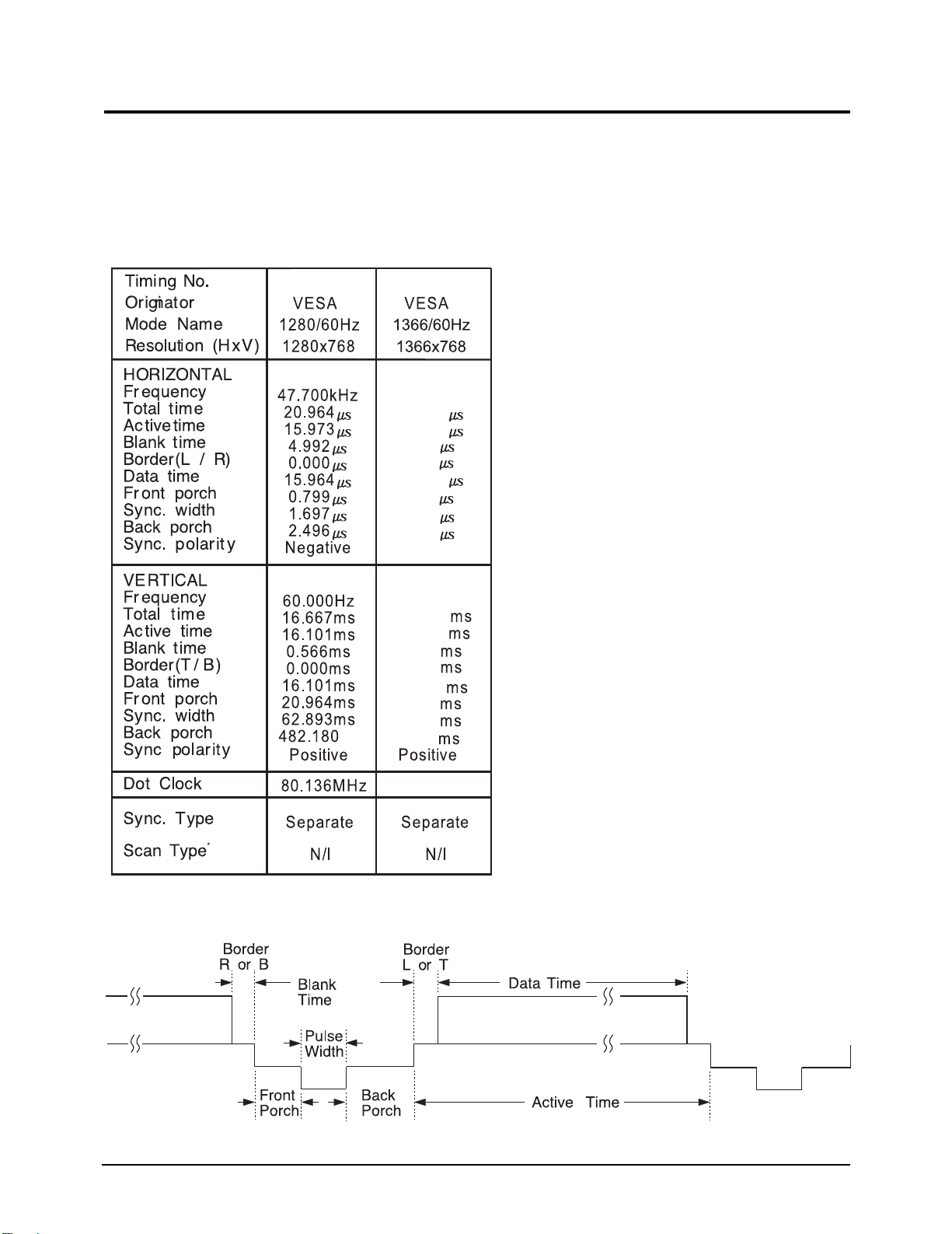
2-5 Timing Chart
This section of the service manual describes the timing that the computer industry recognizes as standard for
computer-generated video signals.
2-5-1 LCD Panel Mode1 mode
47.712kHz
20.959
15.906
5.053
0.000
15.906
0.749
1.702
2.994
Positive
60.015Hz
16.662
16.097
0.566
0.000
16.097
0.063
0.105
0.377
85.500MHz
2-6
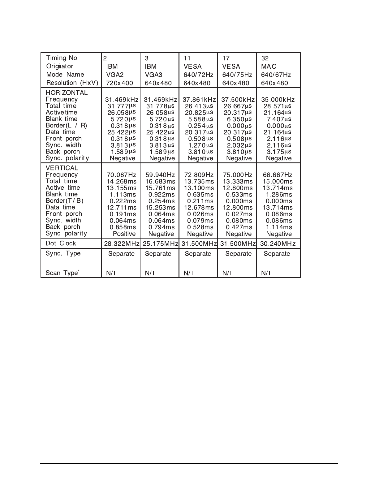
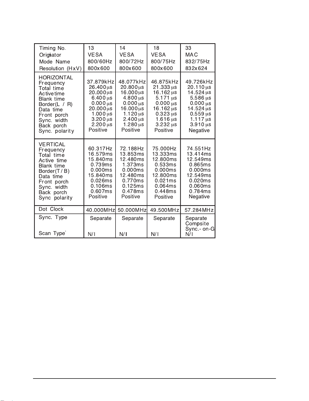
2-5-1 Supported Modes (1)
2 Product Specifications
2-7
2 Product Specifications
2-5-1 Supported Modes (2)
2-8
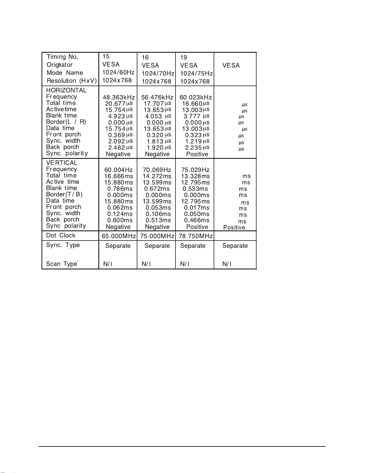
2-5-1 Supported Modes (3)
2 Product Specifications
1360/60Hz
1360x768
47.712kHz
20.959
15.906
5.053
0.000
15.906
0.749
1.702
2.994
Positive
60.015Hz
16.662
16.097
0.566
0.000
16.097
0.063
0.105
0.377
85.500MHz
2-9

2 Product Specifications
Memo
2-10
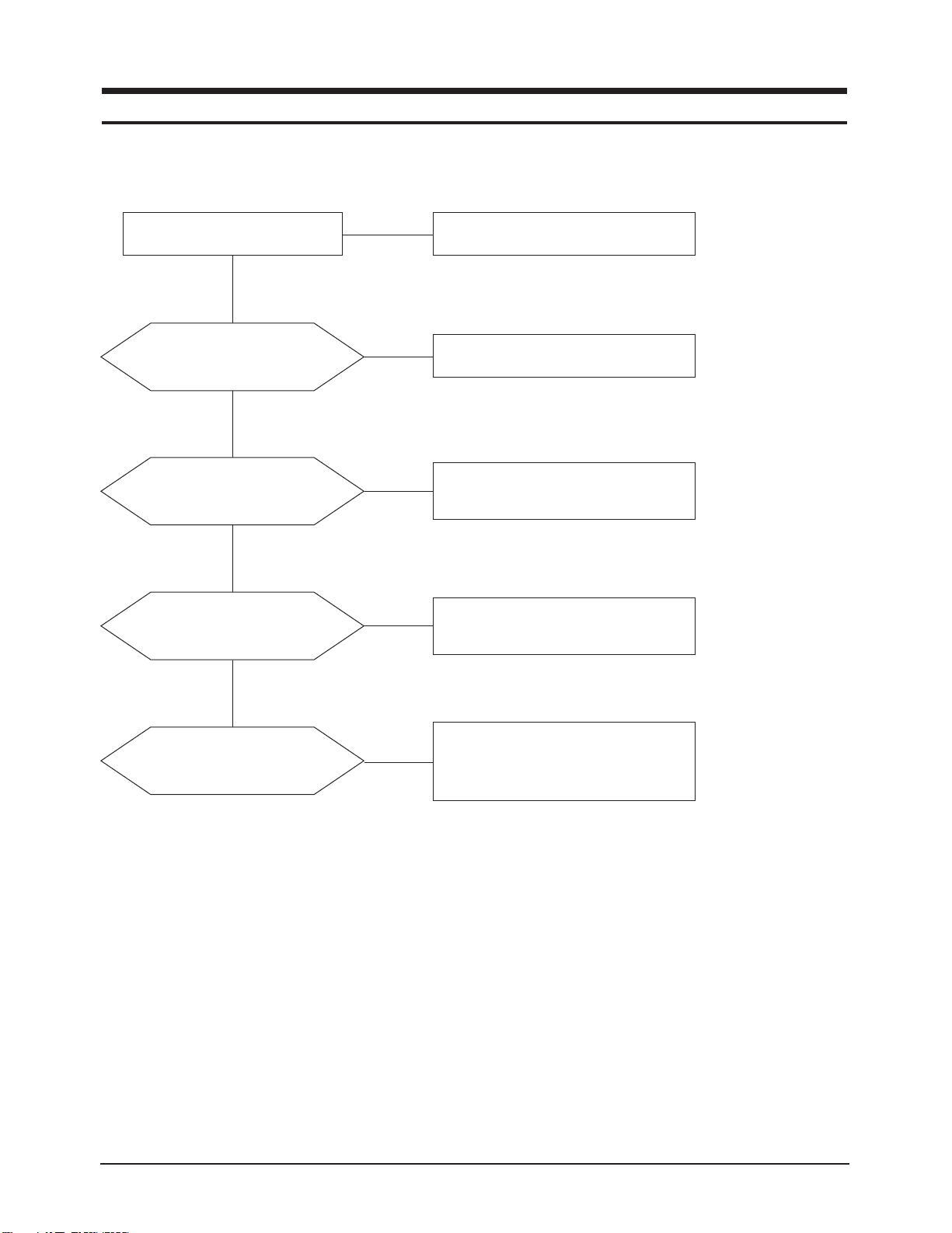
5 Troubleshooting
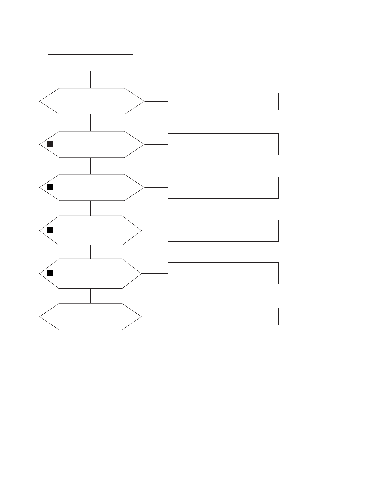
5-1 No Power
5 Troubleshooting
LAMP off, power indicator
LED red color?
Yes
Does proper DC 12V
appear at C801, C807?
Yes
Does proper DC A3.3V,
A5V appear at
C865, C863?
Yes
Does proper DC 5V, 3.3V,
1.9V appear at C870, C861,
C847?
No
No
No
No
Check a connection a power cable.
Change a Assy PCB Power.
Check a IC812, IC801.
Change a main PCB ass'y.
Check a IC813, IC811, IC807.
Change a main PCB ass'y.
Yes
A power is supplied to set?
No
Check a other function.
(No picture part)
Replace a lcd panel.
5-1
5 Troubleshooting
5-2 No Video (Analog PC Signal)
Power Indicator is off.
Lamp on, no video.
Yes
Check a PC source and check
the connection of DSUB cable?
Yes
Does the signal appear at
1
#3, 5, 7(R, G, B) of IC906?
Yes
Does the signal appear at
1
#21,19,15(R,G,B)of IC906?
Yes
Does the digital data appear
2
Does the digital data appear at
3
at output of
DIN(0:23)of IC312?
Yes
output of
LVDS TX(FT250~253)?
No
No
No
No
No
Input a analog PC signal and
connected cable(DPMS).
PC cable. Change a PC
cable. Change a main PCB ass'y.
Check a IC906.
Change a main PCB ass'y.
Check a IC312.
Change a main PCB ass'y.
Check a IC201.
Change a main PCB ass'y.
5-2
Yes
Check a LVDS cable?
Replace a lcd panel?
No
Please, Call to Samsung Co. LTD.
 Loading...